WO2012114703A1 - 回転速度検出装置 - Google Patents
回転速度検出装置 Download PDFInfo
- Publication number
- WO2012114703A1 WO2012114703A1 PCT/JP2012/001092 JP2012001092W WO2012114703A1 WO 2012114703 A1 WO2012114703 A1 WO 2012114703A1 JP 2012001092 W JP2012001092 W JP 2012001092W WO 2012114703 A1 WO2012114703 A1 WO 2012114703A1
- Authority
- WO
- WIPO (PCT)
- Prior art keywords
- case
- detection
- fixing member
- rotational speed
- detection unit
- Prior art date
- Legal status (The legal status is an assumption and is not a legal conclusion. Google has not performed a legal analysis and makes no representation as to the accuracy of the status listed.)
- Ceased
Links
Images



Classifications
-
- G—PHYSICS
- G01—MEASURING; TESTING
- G01P—MEASURING LINEAR OR ANGULAR SPEED, ACCELERATION, DECELERATION, OR SHOCK; INDICATING PRESENCE, ABSENCE, OR DIRECTION, OF MOVEMENT
- G01P3/00—Measuring linear or angular speed; Measuring differences of linear or angular speeds
- G01P3/42—Devices characterised by the use of electric or magnetic means
- G01P3/44—Devices characterised by the use of electric or magnetic means for measuring angular speed
-
- G—PHYSICS
- G01—MEASURING; TESTING
- G01P—MEASURING LINEAR OR ANGULAR SPEED, ACCELERATION, DECELERATION, OR SHOCK; INDICATING PRESENCE, ABSENCE, OR DIRECTION, OF MOVEMENT
- G01P3/00—Measuring linear or angular speed; Measuring differences of linear or angular speeds
- G01P3/42—Devices characterised by the use of electric or magnetic means
- G01P3/44—Devices characterised by the use of electric or magnetic means for measuring angular speed
- G01P3/48—Devices characterised by the use of electric or magnetic means for measuring angular speed by measuring frequency of generated current or voltage
- G01P3/481—Devices characterised by the use of electric or magnetic means for measuring angular speed by measuring frequency of generated current or voltage of pulse signals
- G01P3/487—Devices characterised by the use of electric or magnetic means for measuring angular speed by measuring frequency of generated current or voltage of pulse signals delivered by rotating magnets
-
- B—PERFORMING OPERATIONS; TRANSPORTING
- B29—WORKING OF PLASTICS; WORKING OF SUBSTANCES IN A PLASTIC STATE IN GENERAL
- B29C—SHAPING OR JOINING OF PLASTICS; SHAPING OF MATERIAL IN A PLASTIC STATE, NOT OTHERWISE PROVIDED FOR; AFTER-TREATMENT OF THE SHAPED PRODUCTS, e.g. REPAIRING
- B29C45/00—Injection moulding, i.e. forcing the required volume of moulding material through a nozzle into a closed mould; Apparatus therefor
- B29C45/14—Injection moulding, i.e. forcing the required volume of moulding material through a nozzle into a closed mould; Apparatus therefor incorporating preformed parts or layers, e.g. injection moulding around inserts or for coating articles
-
- F—MECHANICAL ENGINEERING; LIGHTING; HEATING; WEAPONS; BLASTING
- F16—ENGINEERING ELEMENTS AND UNITS; GENERAL MEASURES FOR PRODUCING AND MAINTAINING EFFECTIVE FUNCTIONING OF MACHINES OR INSTALLATIONS; THERMAL INSULATION IN GENERAL
- F16C—SHAFTS; FLEXIBLE SHAFTS; ELEMENTS OR CRANKSHAFT MECHANISMS; ROTARY BODIES OTHER THAN GEARING ELEMENTS; BEARINGS
- F16C41/00—Other accessories, e.g. devices integrated in the bearing not relating to the bearing function as such
- F16C41/007—Encoders, e.g. parts with a plurality of alternating magnetic poles
-
- G—PHYSICS
- G01—MEASURING; TESTING
- G01P—MEASURING LINEAR OR ANGULAR SPEED, ACCELERATION, DECELERATION, OR SHOCK; INDICATING PRESENCE, ABSENCE, OR DIRECTION, OF MOVEMENT
- G01P3/00—Measuring linear or angular speed; Measuring differences of linear or angular speeds
- G01P3/42—Devices characterised by the use of electric or magnetic means
- G01P3/44—Devices characterised by the use of electric or magnetic means for measuring angular speed
- G01P3/443—Devices characterised by the use of electric or magnetic means for measuring angular speed mounted in bearings
Definitions
- the present invention relates to a rotational speed detection device.
- Patent Document 1 there is known a rotational speed detection device including a sensor fixed by resin molding to an annular fixing member.
- the magnetic field changes when the rotation detection target (magnetic encoder) provided on the rotation shaft rotates.
- the change in the magnetic field is read by a sensor to detect the rotational speed.
- the rotational speed detection apparatus of patent document 1 has provided the fixing member separately from the sensor. Therefore, even if the rotational speed detection device is used for rotational axes of different diameters, the sensor can be attached to the rotational speed detection device by changing the fixing member. Thus, the sensor can be generalized.
- the sensor is positioned at a predetermined position with respect to the fixing member by a mold and fixed by a resin mold portion.
- a resin mold portion since it is necessary to fix the two parts of the sensor and the fixing member in the mold with the resin mold portion, it is difficult to obtain the positioning accuracy between the sensor and the fixing member.
- a rotational speed detection device comprises an annular fixing member to be fixed to a support member rotatably supporting a rotation detection target, and a case attached to the fixing member.
- a detection unit that is in contact with a contact portion provided in the case so as to be positioned with respect to the case, and the detection unit is in contact with the case
- a resin mold portion formed by resin molding for fixing the detection portion to the case in a state of being in contact with the portion.
- the detection unit since the detection unit is positioned in contact with the case previously attached to the fixing member, positioning can be performed for each member, and the positioning accuracy between the detection unit and the fixing member can be improved. Further, when the detection unit is in contact with the case and positioned, the mounting position is determined not by the pressing and fixing by the mold but by the contact portion, so that the stress from the mold can be suitably suppressed on the detection unit. Furthermore, when the position of the rotation detection target is different, the detection unit can be positioned with respect to the rotation detection target by using different cases. Therefore, the mold which imitates the resin mold part can be made common.
- the case is formed by resin molding, and a detection unit insertion hole into which the detection unit is inserted in the fixing member, and resin forming the case on both sides of the detection unit insertion hole in the circumferential direction of the fixing member. And the through-hole which flows in may be provided.
- the fixing member and the case can be fixed after resin molding of the case. Therefore, when assembling the detection unit, the positions of the fixing member and the case do not change, so that the positioning accuracy between the detection unit and the fixing member can be improved.
- a case fixed to an annular fixing member to be fixed to a support member rotatably supporting a rotation detection target is formed by resin molding.
- Positioning the detection unit with respect to the case by bringing the detection unit for detecting the rotation speed of the rotation detection target into contact with the contact portion provided in the case, and resin formed by resin molding Fixing the detection unit positioned with respect to the case by the mold unit to the case.
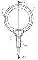
- FIG. 6 is a cross-sectional view of the rotational speed detection device taken along line VI-VI of FIG. 5;
- a rotational speed detection device according to the present embodiment will be described based on the drawings.
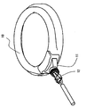
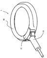
- the rotational speed detection device 1 includes an annular fixing member 10 to be fixed to a bearing outer ring (supporting member) 24 rotatably supporting a magnetic encoder (rotation detection target) 22, and a case 11 attached to the fixing member 10.
- the detection unit (sensor) 12 in contact with the contact portion 11b provided on the case 11 so as to be positioned with respect to the case 11 in order to detect the rotational speed of the magnetic encoder 22, and the detection unit 12 And a resin mold portion 13 formed by resin molding for fixing the detection portion 12 to the case 11 in a state of being in contact with the contact portion 11b.
- the case 11 is formed by resin molding, and the fixing member 10 is provided with a first detection portion insertion hole 10a into which the detection portion 12 is inserted, and both sides of the first detection portion insertion hole 10a in the circumferential direction of the fixing member 10 And a through hole 10b through which the resin constituting 11 flows.
- the fixing member 10 is formed in an annular shape. Further, the fixing member 10 is provided with a first detection portion insertion hole 10 a which is opened in the circumferential direction of the fixing member 10 by a predetermined length. Furthermore, the fixing member 10 is penetrated in the axial direction of the fixing member 10, and the through holes 10b are provided on both sides of the first detection portion insertion hole 10a in the circumferential direction of the fixing member 10.
- a case 11 is formed by resin molding so as to surround the first detection portion insertion hole 10a and the through hole 10b.
- the resin flows into the through hole 10 b of the fixing member 10.
- the fixing member 10 and the case 11 are fixed by the solidification of the resin constituting the case 11.
- a second detection portion insertion hole 11 a is formed inside the first detection portion insertion hole 10 a.
- the distal end 12a (FIG. 6) of the detection unit 12 is inserted into the second detection unit insertion hole 11a of the case 11 as shown in FIG.
- the tip 12a of the detection unit 12 is inserted into the second detection unit insertion hole 11a.
- the insertion movement of the detection unit 12 is restricted at a predetermined position, and the position is determined.
- the predetermined position is a position suitable for the detection unit 12 to detect the rotational speed of the rotation detection target 22.
- the tip 12a of the detection portion 12 is inserted into the inside of the fixing member 10 through the first detection portion insertion hole 10a.
- the resin mold portion 13 is covered so that the outer peripheral side of the case 11 and the detection unit 12 is covered by resin molding as shown in FIG. Form.
- the tip 12 a of the detection unit 12 may or may not be covered by the resin mold portion 13.
- the detection unit 12 is fixed by the resin mold unit 13 so as not to be removable from the case 11.
- the resin mold portion 13 may be formed to fix the fixing member 10, the case 11, and the detection unit 12.
- the rotational speed detection device 1 of the present embodiment is used, for example, as a wheel speed detection unit.
- the detection unit 12 detects the rotation speed of the magnetic encoder (rotation detection target) 22 provided on the hub 20 of the wheel using a standard type magnetic sensor.
- the fixing member 10 is fixed to a bearing outer ring (supporting member) 24 rotatably supporting a hub 20 provided with the magnetic encoder 22.
- a lip seal 26 seals between the fixing member 10 and the hub 20.
- a seal member 28 seals between the fixed member 10 and the magnetic encoder 22.
- the detection unit 12 is positioned such that the tip 12 a of the detection unit 12 faces the magnetic encoder 22 when the contact unit 12 b of the detection unit 12 abuts on the contact unit 11 b of the case 11.
- the detection unit 12 is positioned in contact with the case 11. Therefore, even if the position of the magnetic encoder 22 as the rotation detection target is different, if the case 11 is changed according to the position of the magnetic encoder 22, the detection unit 12 is fixed at an appropriate position with respect to the magnetic encoder 22. be able to. Therefore, the detection unit 12 and the fixing member 10 can be used widely. Therefore, since it is not necessary to prepare many kinds of detectors 12 and fixing members 10, the rotational speed detector 1 can be provided at low cost.
- the detection unit 12 is positioned in contact with the contact portion 11 b of the case 11 previously attached to the fixing member 10, so that each member (the fixing member 10 and the case 11, and the case 11) And the detection unit 12) can position each member. Therefore, the positioning accuracy between the detection unit 12 and the fixing member 10 can be improved. Further, when positioning the detection unit 12 in contact with the case 11, the attachment position of the detection unit 12 is determined by the contact portion 11b, not by pressing and fixing with a mold. Therefore, the application of stress (pressure) from the mold to the detection unit 12 can be suitably suppressed. Furthermore, even when the position of the rotation detection target is different, the detection unit 12 can be properly positioned by changing the case 11.
- the metal mold which imitates the resin mold part 13 can be made common.
- the advantage that the resin mold part 13 is not in contact with the fixing member 10 is as follows. If the fixing member 10 is changed, the rotation speed detection device 1 can be applied to rotation detection targets of different diameters. Therefore, there is no need to change the mold that imitates the resin mold portion 13.
- the case 11 can be fixed to the fixing member 10 after resin molding of the case 11. Therefore, since the positional relationship between the fixed member 10 and the case 11 does not change when the detection unit 12 is assembled, the positioning accuracy of the detection unit 12 with respect to the fixed member 10 can be improved.
- Rotational speed detection device 10 Fixed member 10a: First detection portion insertion hole (detection portion insertion hole) 10b: Through hole 11: Case 11a: Insertion of second detection portion Hole 11b: Contact portion 12: Detection portion 13: Resin mold portion 22: Magnetic encoder (rotational detection target)
Landscapes
- Engineering & Computer Science (AREA)
- Physics & Mathematics (AREA)
- General Physics & Mathematics (AREA)
- General Engineering & Computer Science (AREA)
- Mechanical Engineering (AREA)
- Manufacturing & Machinery (AREA)
- Transmission And Conversion Of Sensor Element Output (AREA)
Abstract
Description
10・・・固定部材
10a・・・第1検出部挿入孔(検出部挿入孔)10b・・・貫通孔
11・・・ケース
11a・・・第2検出部挿入孔
11b・・・当接部
12・・・検出部
13・・・樹脂モールド部
22・・・磁気エンコータ(回転検出対象)
Claims (5)
- 回転検出対象を回転可能に支持する支持部材に固定されるべき環状の固定部材と、
前記固定部材に取り付けられたケースと、
前記回転検出対象の回転速度を検出するために、前記ケースに対して位置決めされるように前記ケースに設けられた当接部に当接した検出部と、
前記検出部が前記ケースの前記当接部に当接した状態で前記検出部を前記ケースに固定する樹脂成形により形成された樹脂モールド部と、を有する回転速度検出装置。 - 前記ケースは、樹脂成形により形成され、
前記固定部材には、前記検出部が挿入される検出部挿入孔と、前記固定部材の周方向において前記検出部挿入孔の両側に前記ケースを構成する樹脂が流れ込む貫通孔と、が設けられる請求項1に記載の回転速度検出装置。 - 前記検出部は、前記ケースの前記当接部に当接する当接部を有し、
前記検出部の前記当接部が前記ケースの前記当接部に当接することにより、前記検出部は、前記回転検出対象の回転速度を検出するのに適した所定位置に位置決めされる請求項1または2に記載の回転速度検出装置。 - 前記樹脂モールド部は、前記固定部材、前記ケース、及び前記検出部を固定する請求項1ないし3のいずれか一項に記載の回転速度検出装置。
- 回転検出対象を回転可能に支持する支持部材に固定されるべき環状の固定部材に固定されたケースを、樹脂成形により形成することと、
前記回転検出対象の回転速度を検出する検出部を前記ケースに設けられた当接部に当接させることにより、前記検出部を、前記ケースに対して位置決めすることと、
樹脂成形により形成された樹脂モールド部により、前記ケースに対して位置決めされた前記検出部を、前記ケースに固定することと、を有する回転速度検出装置の製造方法。
Priority Applications (2)
| Application Number | Priority Date | Filing Date | Title |
|---|---|---|---|
| US13/979,727 US20130285650A1 (en) | 2011-02-24 | 2012-02-20 | Rotation speed detecting apparatus |
| CN201290000243.XU CN203432990U (zh) | 2011-02-24 | 2012-02-20 | 转速检测装置 |
Applications Claiming Priority (4)
| Application Number | Priority Date | Filing Date | Title |
|---|---|---|---|
| JP2011-037976 | 2011-02-24 | ||
| JP2011037976 | 2011-02-24 | ||
| JP2011090529A JP2012189566A (ja) | 2011-02-24 | 2011-04-14 | 回転速度検出装置 |
| JP2011-090529 | 2011-04-14 |
Publications (1)
| Publication Number | Publication Date |
|---|---|
| WO2012114703A1 true WO2012114703A1 (ja) | 2012-08-30 |
Family
ID=46720498
Family Applications (1)
| Application Number | Title | Priority Date | Filing Date |
|---|---|---|---|
| PCT/JP2012/001092 Ceased WO2012114703A1 (ja) | 2011-02-24 | 2012-02-20 | 回転速度検出装置 |
Country Status (4)
| Country | Link |
|---|---|
| US (1) | US20130285650A1 (ja) |
| JP (1) | JP2012189566A (ja) |
| CN (1) | CN203432990U (ja) |
| WO (1) | WO2012114703A1 (ja) |
Cited By (1)
| Publication number | Priority date | Publication date | Assignee | Title |
|---|---|---|---|---|
| WO2014054481A1 (ja) * | 2012-10-03 | 2014-04-10 | アイシン精機株式会社 | センサユニット |
Citations (3)
| Publication number | Priority date | Publication date | Assignee | Title |
|---|---|---|---|---|
| JPH08201409A (ja) * | 1995-01-31 | 1996-08-09 | Sumitomo Electric Ind Ltd | カバー一体型回転センサ |
| JP2004361362A (ja) * | 2003-06-09 | 2004-12-24 | Ntn Corp | 回転センサ付き転がり軸受 |
| JP2009264941A (ja) * | 2008-04-25 | 2009-11-12 | Denso Corp | 回転速度検出装置 |
-
2011
- 2011-04-14 JP JP2011090529A patent/JP2012189566A/ja active Pending
-
2012
- 2012-02-20 CN CN201290000243.XU patent/CN203432990U/zh not_active Expired - Fee Related
- 2012-02-20 WO PCT/JP2012/001092 patent/WO2012114703A1/ja not_active Ceased
- 2012-02-20 US US13/979,727 patent/US20130285650A1/en not_active Abandoned
Patent Citations (3)
| Publication number | Priority date | Publication date | Assignee | Title |
|---|---|---|---|---|
| JPH08201409A (ja) * | 1995-01-31 | 1996-08-09 | Sumitomo Electric Ind Ltd | カバー一体型回転センサ |
| JP2004361362A (ja) * | 2003-06-09 | 2004-12-24 | Ntn Corp | 回転センサ付き転がり軸受 |
| JP2009264941A (ja) * | 2008-04-25 | 2009-11-12 | Denso Corp | 回転速度検出装置 |
Cited By (3)
| Publication number | Priority date | Publication date | Assignee | Title |
|---|---|---|---|---|
| WO2014054481A1 (ja) * | 2012-10-03 | 2014-04-10 | アイシン精機株式会社 | センサユニット |
| JP2014074619A (ja) * | 2012-10-03 | 2014-04-24 | Aisin Seiki Co Ltd | センサユニット |
| US9561608B2 (en) | 2012-10-03 | 2017-02-07 | Aisin Seiki Kabushiki Kaisha | Sensor unit |
Also Published As
| Publication number | Publication date |
|---|---|
| JP2012189566A (ja) | 2012-10-04 |
| US20130285650A1 (en) | 2013-10-31 |
| CN203432990U (zh) | 2014-02-12 |
Similar Documents
| Publication | Publication Date | Title |
|---|---|---|
| JP2010509604A (ja) | ステアリングコラムの軸におけるトルク検出装置 | |
| JP2010078366A (ja) | 角度検出装置 | |
| JP2008002979A (ja) | トルク検出装置及びヨーク組立体の製造方法 | |
| EP3009802B1 (en) | Sensing device and method for manufacturing sensing device | |
| WO2014174870A1 (ja) | 磁気エンコーダ | |
| JP4862685B2 (ja) | エンコーダ付深溝型玉軸受及び自動二輪車用の車輪の回転速度検出装置 | |
| WO2009116445A1 (ja) | 回転センサ付軸受 | |
| JP5857470B2 (ja) | センサ付き転がり軸受装置 | |
| JP2013142702A (ja) | トルク検出用のセンサシステム | |
| JP5128120B2 (ja) | 回転センサ | |
| JPWO2018092207A1 (ja) | 回転位置検出装置 | |
| WO2015010736A1 (en) | A sensor-bearing unit, a mechanical system comprising at least one such unit and implementing methods | |
| JP6713269B2 (ja) | 回転検出装置付き軸受 | |
| JP2008128740A (ja) | 回転センサ | |
| JP2012189566A (ja) | 回転速度検出装置 | |
| JP5013535B2 (ja) | 回転角検出装置 | |
| WO2009031557A1 (ja) | 角度センサ | |
| JP2006010346A (ja) | ポジションセンサ | |
| JP2005106653A (ja) | 回転量検出装置 | |
| JP2005233849A (ja) | 回転検出装置 | |
| JP4343585B2 (ja) | 絶対角度センサ付軸受装置およびその使用方法 | |
| JP4293058B2 (ja) | 回転速度検出装置 | |
| JP2007212177A (ja) | ボールねじ用トルク変動測定装置 | |
| JP2006098235A (ja) | 回転角センサ | |
| JP4587656B2 (ja) | アブソリュートエンコーダ付軸受 |
Legal Events
| Date | Code | Title | Description |
|---|---|---|---|
| WWE | Wipo information: entry into national phase |
Ref document number: 201290000243.X Country of ref document: CN |
|
| 121 | Ep: the epo has been informed by wipo that ep was designated in this application |
Ref document number: 12749343 Country of ref document: EP Kind code of ref document: A1 |
|
| WWE | Wipo information: entry into national phase |
Ref document number: 13979727 Country of ref document: US |
|
| NENP | Non-entry into the national phase |
Ref country code: DE |
|
| 122 | Ep: pct application non-entry in european phase |
Ref document number: 12749343 Country of ref document: EP Kind code of ref document: A1 |