WO2012114533A1 - Machining center - Google Patents
Machining center Download PDFInfo
- Publication number
- WO2012114533A1 WO2012114533A1 PCT/JP2011/054824 JP2011054824W WO2012114533A1 WO 2012114533 A1 WO2012114533 A1 WO 2012114533A1 JP 2011054824 W JP2011054824 W JP 2011054824W WO 2012114533 A1 WO2012114533 A1 WO 2012114533A1
- Authority
- WO
- WIPO (PCT)
- Prior art keywords
- tool
- spindle
- shutter
- tool magazine
- magazine
- Prior art date
Links
Images


Classifications
-
- B—PERFORMING OPERATIONS; TRANSPORTING
- B23—MACHINE TOOLS; METAL-WORKING NOT OTHERWISE PROVIDED FOR
- B23Q—DETAILS, COMPONENTS, OR ACCESSORIES FOR MACHINE TOOLS, e.g. ARRANGEMENTS FOR COPYING OR CONTROLLING; MACHINE TOOLS IN GENERAL CHARACTERISED BY THE CONSTRUCTION OF PARTICULAR DETAILS OR COMPONENTS; COMBINATIONS OR ASSOCIATIONS OF METAL-WORKING MACHINES, NOT DIRECTED TO A PARTICULAR RESULT
- B23Q3/00—Devices holding, supporting, or positioning work or tools, of a kind normally removable from the machine
- B23Q3/155—Arrangements for automatic insertion or removal of tools, e.g. combined with manual handling
- B23Q3/157—Arrangements for automatic insertion or removal of tools, e.g. combined with manual handling of rotary tools
- B23Q3/15713—Arrangements for automatic insertion or removal of tools, e.g. combined with manual handling of rotary tools a transfer device taking a single tool from a storage device and inserting it in a spindle
- B23Q3/1572—Arrangements for automatic insertion or removal of tools, e.g. combined with manual handling of rotary tools a transfer device taking a single tool from a storage device and inserting it in a spindle the storage device comprising rotating or circulating storing means
- B23Q3/15722—Rotary discs or drums
-
- B—PERFORMING OPERATIONS; TRANSPORTING
- B23—MACHINE TOOLS; METAL-WORKING NOT OTHERWISE PROVIDED FOR
- B23Q—DETAILS, COMPONENTS, OR ACCESSORIES FOR MACHINE TOOLS, e.g. ARRANGEMENTS FOR COPYING OR CONTROLLING; MACHINE TOOLS IN GENERAL CHARACTERISED BY THE CONSTRUCTION OF PARTICULAR DETAILS OR COMPONENTS; COMBINATIONS OR ASSOCIATIONS OF METAL-WORKING MACHINES, NOT DIRECTED TO A PARTICULAR RESULT
- B23Q11/00—Accessories fitted to machine tools for keeping tools or parts of the machine in good working condition or for cooling work; Safety devices specially combined with or arranged in, or specially adapted for use in connection with, machine tools
- B23Q11/08—Protective coverings for parts of machine tools; Splash guards
-
- B—PERFORMING OPERATIONS; TRANSPORTING
- B23—MACHINE TOOLS; METAL-WORKING NOT OTHERWISE PROVIDED FOR
- B23Q—DETAILS, COMPONENTS, OR ACCESSORIES FOR MACHINE TOOLS, e.g. ARRANGEMENTS FOR COPYING OR CONTROLLING; MACHINE TOOLS IN GENERAL CHARACTERISED BY THE CONSTRUCTION OF PARTICULAR DETAILS OR COMPONENTS; COMBINATIONS OR ASSOCIATIONS OF METAL-WORKING MACHINES, NOT DIRECTED TO A PARTICULAR RESULT
- B23Q3/00—Devices holding, supporting, or positioning work or tools, of a kind normally removable from the machine
- B23Q3/155—Arrangements for automatic insertion or removal of tools, e.g. combined with manual handling
- B23Q3/1552—Arrangements for automatic insertion or removal of tools, e.g. combined with manual handling parts of devices for automatically inserting or removing tools
- B23Q3/15526—Storage devices; Drive mechanisms therefor
- B23Q3/15533—Storage devices; Drive mechanisms therefor combined with manual tool transfers
-
- B—PERFORMING OPERATIONS; TRANSPORTING
- B23—MACHINE TOOLS; METAL-WORKING NOT OTHERWISE PROVIDED FOR
- B23Q—DETAILS, COMPONENTS, OR ACCESSORIES FOR MACHINE TOOLS, e.g. ARRANGEMENTS FOR COPYING OR CONTROLLING; MACHINE TOOLS IN GENERAL CHARACTERISED BY THE CONSTRUCTION OF PARTICULAR DETAILS OR COMPONENTS; COMBINATIONS OR ASSOCIATIONS OF METAL-WORKING MACHINES, NOT DIRECTED TO A PARTICULAR RESULT
- B23Q3/00—Devices holding, supporting, or positioning work or tools, of a kind normally removable from the machine
- B23Q3/155—Arrangements for automatic insertion or removal of tools, e.g. combined with manual handling
- B23Q3/157—Arrangements for automatic insertion or removal of tools, e.g. combined with manual handling of rotary tools
- B23Q3/15706—Arrangements for automatic insertion or removal of tools, e.g. combined with manual handling of rotary tools a single tool being inserted in a spindle directly from a storage device, i.e. without using transfer devices
-
- B—PERFORMING OPERATIONS; TRANSPORTING
- B23—MACHINE TOOLS; METAL-WORKING NOT OTHERWISE PROVIDED FOR
- B23Q—DETAILS, COMPONENTS, OR ACCESSORIES FOR MACHINE TOOLS, e.g. ARRANGEMENTS FOR COPYING OR CONTROLLING; MACHINE TOOLS IN GENERAL CHARACTERISED BY THE CONSTRUCTION OF PARTICULAR DETAILS OR COMPONENTS; COMBINATIONS OR ASSOCIATIONS OF METAL-WORKING MACHINES, NOT DIRECTED TO A PARTICULAR RESULT
- B23Q11/00—Accessories fitted to machine tools for keeping tools or parts of the machine in good working condition or for cooling work; Safety devices specially combined with or arranged in, or specially adapted for use in connection with, machine tools
- B23Q11/08—Protective coverings for parts of machine tools; Splash guards
- B23Q11/0891—Protective coverings for parts of machine tools; Splash guards arranged between the working area and the operator
-
- Y—GENERAL TAGGING OF NEW TECHNOLOGICAL DEVELOPMENTS; GENERAL TAGGING OF CROSS-SECTIONAL TECHNOLOGIES SPANNING OVER SEVERAL SECTIONS OF THE IPC; TECHNICAL SUBJECTS COVERED BY FORMER USPC CROSS-REFERENCE ART COLLECTIONS [XRACs] AND DIGESTS
- Y10—TECHNICAL SUBJECTS COVERED BY FORMER USPC
- Y10T—TECHNICAL SUBJECTS COVERED BY FORMER US CLASSIFICATION
- Y10T483/00—Tool changing
- Y10T483/11—Tool changing with safety means
- Y10T483/115—Guard
-
- Y—GENERAL TAGGING OF NEW TECHNOLOGICAL DEVELOPMENTS; GENERAL TAGGING OF CROSS-SECTIONAL TECHNOLOGIES SPANNING OVER SEVERAL SECTIONS OF THE IPC; TECHNICAL SUBJECTS COVERED BY FORMER USPC CROSS-REFERENCE ART COLLECTIONS [XRACs] AND DIGESTS
- Y10—TECHNICAL SUBJECTS COVERED BY FORMER USPC
- Y10T—TECHNICAL SUBJECTS COVERED BY FORMER US CLASSIFICATION
- Y10T483/00—Tool changing
- Y10T483/17—Tool changing including machine tool or component
- Y10T483/1733—Rotary spindle machine tool [e.g., milling machine, boring, machine, grinding machine, etc.]
- Y10T483/1736—Tool having specific mounting or work treating feature
- Y10T483/1743—Tool having specific mounting or work treating feature including means for angularly orienting tool and spindle
-
- Y—GENERAL TAGGING OF NEW TECHNOLOGICAL DEVELOPMENTS; GENERAL TAGGING OF CROSS-SECTIONAL TECHNOLOGIES SPANNING OVER SEVERAL SECTIONS OF THE IPC; TECHNICAL SUBJECTS COVERED BY FORMER USPC CROSS-REFERENCE ART COLLECTIONS [XRACs] AND DIGESTS
- Y10—TECHNICAL SUBJECTS COVERED BY FORMER USPC
- Y10T—TECHNICAL SUBJECTS COVERED BY FORMER US CLASSIFICATION
- Y10T483/00—Tool changing
- Y10T483/17—Tool changing including machine tool or component
- Y10T483/1733—Rotary spindle machine tool [e.g., milling machine, boring, machine, grinding machine, etc.]
- Y10T483/179—Direct tool exchange between spindle and matrix
- Y10T483/1793—Spindle comprises tool changer
- Y10T483/1795—Matrix indexes selected tool to transfer position
-
- Y—GENERAL TAGGING OF NEW TECHNOLOGICAL DEVELOPMENTS; GENERAL TAGGING OF CROSS-SECTIONAL TECHNOLOGIES SPANNING OVER SEVERAL SECTIONS OF THE IPC; TECHNICAL SUBJECTS COVERED BY FORMER USPC CROSS-REFERENCE ART COLLECTIONS [XRACs] AND DIGESTS
- Y10—TECHNICAL SUBJECTS COVERED BY FORMER USPC
- Y10T—TECHNICAL SUBJECTS COVERED BY FORMER US CLASSIFICATION
- Y10T483/00—Tool changing
- Y10T483/18—Tool transfer to or from matrix
- Y10T483/1873—Indexing matrix
- Y10T483/1882—Rotary disc
Landscapes
- Engineering & Computer Science (AREA)
- Mechanical Engineering (AREA)
- Automatic Tool Replacement In Machine Tools (AREA)
Abstract
Description
しかしながら、上記特許文献1記載のマシニングセンタのように工具マガジンを傾斜して設ける場合には、マシニングセンタの全高が高くなりやすい。とくに、加工領域と工具マガジンとの間に水平方向に仕切壁としての開閉可能なシャッターを設ける場合には、工具マガジンをシャッターと干渉しない位置に取り付ける必要がある。このため、マシニングセンタの全高が一層高くなりやすく、機械の安定性を損なう。 There is known a machining center in which a tool magazine is rotatably mounted above a machining area and a tool is automatically exchanged between the tool magazine and a spindle (see, for example, Patent Document 1). In the machining center described in Patent Document 1, a door is provided in front of the spindle so as to be openable and closable so as to face the machining area in order to perform work replacement work or the like in the machining area. Furthermore, in order to facilitate the work exchange operation and the like, the tool magazine is inclined so that the door side is high and the spindle side is low.
However, when the tool magazine is inclined and provided as in the machining center described in Patent Document 1, the overall height of the machining center tends to be high. In particular, when a shutter that can be opened and closed as a partition wall is provided between the machining region and the tool magazine in the horizontal direction, it is necessary to attach the tool magazine at a position that does not interfere with the shutter. For this reason, the overall height of the machining center tends to be higher, which impairs the stability of the machine.
図2は、本発明の実施の形態に係るマシニングセンタの外観斜視図である。
図3は、図1の矢視III図である。
図4は、図1のマシニングセンタに用いられる工具の一例を示す側面図である。
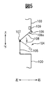
図5は、図2の凹部の構成を概略的に示す縦断面図である。
図6は、本発明の実施の形態に係る工具交換装置の構成をより詳細に示すマシニングセンタの要部側面図であり、工具マガジンの第1傾斜姿勢を示す図である。
図7は、本発明の実施の形態に係る工具交換装置の構成をより詳細に示すマシニングセンタの要部平面図である。
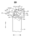
図8は、図6,7のマガジンベースの支持部の構成を模式的に示す側面図である。
図9は、工具マガジンの第2傾斜姿勢を示す図である。
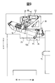
図10は、本発明の実施の形態に係る工具差替装置の構成を示す図である。
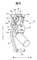
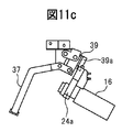
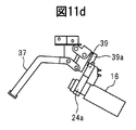
図11a~図11dは、それぞれ図10の工具差替装置を用いた工具差替動作を説明する図である。
図12は、本発明の実施の形態に係るマシニングセンタの制御装置の構成を示すブロック図である。 FIG. 1 is a side view showing a schematic configuration of a machining center according to an embodiment of the present invention.
FIG. 2 is an external perspective view of the machining center according to the embodiment of the present invention.
3 is a view taken along the arrow III in FIG.
FIG. 4 is a side view showing an example of a tool used in the machining center of FIG.
FIG. 5 is a longitudinal sectional view schematically showing the configuration of the recess in FIG.
FIG. 6 is a side view of the main part of the machining center showing the configuration of the tool changer according to the embodiment of the present invention in more detail, and is a view showing the first inclined posture of the tool magazine.
FIG. 7 is a plan view of the main part of the machining center showing the configuration of the tool changer according to the embodiment of the present invention in more detail.
FIG. 8 is a side view schematically showing the configuration of the magazine base support of FIGS.
FIG. 9 is a diagram illustrating a second inclined posture of the tool magazine.
FIG. 10 is a diagram showing a configuration of the tool replacement device according to the embodiment of the present invention.
11a to 11d are diagrams for explaining the tool replacement operation using the tool replacement device of FIG.
FIG. 12 is a block diagram showing the configuration of the machining center control apparatus according to the embodiment of the present invention.
図1に示すように、ベッド10の後面には、直線送り機構を介して上下方向(Y軸方向)に移動可能に上下移動体11が支持されている。上下移動体11の上面には、直線送り機構を介して左右方向(X軸方向)に移動可能に左右移動体12が支持されている。左右移動体12の上面には、直線送り機構を介して前後方向(Z軸方向)に移動可能に前後移動体13が支持されている。前後移動体13の前部には主軸頭14が設けられ、主軸頭14には、前後方向の回転軸線を中心に回転可能な主軸15を介して工具16が取り付けられている。上下方向、左右方向および前後方向の直線送り機構は、例えばガイドレールとガイドブロックによる案内装置、およびボールねじとボールねじを回転駆動するサーボモータによる駆動装置により構成される。工具16は、主軸頭14内のスピンドルモータにより回転駆動される。
ベッド10の上面には、鉛直方向の軸線を中心に回転送り可能にテーブル17が載置されている。テーブル17の上面にはイケール18が載置され、イケール18の前面には工具16の先端部に対向してワークWが取り付けられている。この構成により、ワークWに対して工具16が直交3軸方向(X、Y、Z軸方向)および回転1軸方向(B軸方向)に相対移動可能となり、ワークWを所望の形状に加工することができる。さらに、テーブル17を前後方向の軸線を中心に回転送り可能に構成し、マシニングセンタを直交3軸方向および回転2軸方向(B、C軸方向)に相対移動可能な5軸加工機とすることもできる。
ベッド10の左右側方には、左右一対の支柱19が立設され、支柱19の上端部に工具交換装置20が設けられている。工具交換装置20は、左右の支柱19の上端部に架設されたマガジンベース21と、マガジンベース21に回転可能に支持された工具マガジン22とを有する。マガジンベース21は、前側が高く、後側が低くなるように傾斜して設けられ、工具マガジン22も同様に傾斜して設けられている。すなわち、鉛直線と工具マガジン22の回転軸線とのなす角が所定の傾斜角αとなるように工具マガジン22は傾設されている。
図3は、工具交換装置20の背面図、すなわち、工具交換装置20を傾斜角α方向から見た図(図1の矢視III図)である。図1,3に示すように、マガジンベース21の左右方向中央部には、工具マガジン22の割出用のモータ(割出モータ)50が固定されている。工具マガジン22は、回転フレーム23と、回転フレーム23の周囲に取り付けられた複数の工具保持部、すなわちグリッパ24とを有する。割出モータ50の出力軸は、回転フレーム23の回転中心部に連結され、工具マガジン22はマガジンベース21に図3の点Oを中心にして矢印β方向に回転可能に支持されている。割出モータ50は、例えばサーボモータによって構成される。
本実施の形態の特徴的構成として、図3に示すように回転フレーム23は、円の一部を直線状に切り欠いた形状をなし、円弧部23aと弦部23bとによって外形形状が規定されている。円弧部23aには、周方向等間隔に複数のグリッパ24が取り付けられている。各グリッパ24には、それぞれ交換用工具16が着脱可能に保持され、工具マガジン22の周囲に工具保持領域AR1が形成されている。一方、弦部23bには、グリッパ24が設けられておらず、工具マガジン22の周囲に工具不存在領域AR2が形成されている。なお、図1,3では、工具マガジン22は回転基準状態にあり、回転基準状態では、弦部23bが回転中心Oよりも後方にて左右方向に延在し、工具不存在領域AR2が後方に存在する。
図4は、グリッパ24に保持される工具16の一例を示す側面図である。工具16は、回転軸線に沿ってシャンク16a、フランジ16b、V溝16cおよび工具部16d(図ではドリル)を有する。シャンク16aの周面は後端面に向けて先細のテーパ面形状をなし、主軸15の先端部のテーパ孔(不図示)に密着状態で嵌合し、主軸15に設けられたクランプ装置54(図12)によってクランプされる。なお、クランプ装置54は、例えば工具16のシャンク16aを主軸15の後方に引き込むコレット付きのドローバー等、周知のものである。
工具交換時には、例えば工具マガジン22の回転により、図1に点線で示すように、グリッパ24に装着された工具16を最下部かつ最後方の工具交換位置Paに移動させる。この工具交換位置Paにおいて工具16の軸線方向が前後方向を向くように、工具16は傾斜角αに応じた角度で、工具マガジン22に対し傾斜してグリッパ24に保持されている。
ワークWと工具マガジン22の間には、水平方向に加工領域WSと工具マガジン22とを仕切る水平カバー25が延設されている。この水平カバー25は、切り屑や加工液の工具マガジン22への飛散を防止する機能を有する。水平カバー25の後部には、工具交換位置Paに対応して平面視略矩形状の開口部25a(図7参照)が設けられている。水平カバー25には前後方向にスライド可能にシャッター26が設けられている。シャッター26は開閉用シリンダ53の駆動により前後方向にスライドし、シャッター26によって開口部25aが開閉される。開閉用シリンダ53は例えばエアシリンダにより構成される。なお、シャッター26は左右方向にスライドする方式でも、蝶番方式でも、いかなる構成でもよい。
一方、移動体11~13の前方には主軸頭カバー27が立設され、水平カバー25の下方かつ主軸頭カバー27の前方に加工室(加工領域)WSが形成されている。主軸頭カバー27には開口部27aが設けられ、開口部27aを介して主軸15および工具16が主軸頭カバー27を貫通している。主軸頭カバー27は上下方向および左右方向に巻き取り可能であり、工具16の上下動および左右動に伴い開口部27aも上下、左右に移動する。
図2に示すようにマシニングセンタは全体が略直方体形状をなし、その前後面、左右面および上下面はそれぞれカバー100によって覆われている。前面のカバー100には開口部101が設けられている。開口部101は左右方向にスライド可能な扉102によって開閉され、扉102を開放した状態で加工領域WS内のワークWの交換作業等が行われる。扉102には監視用の窓103が設けられている。
右面のカバー100の一部は内側(左方)に入り込み、凹部104が形成されている。右面カバー100の凹部104の前側には操作盤110が設けられている。図5は、凹部104の構成を概略的に示す縦断面図である。凹部104の奥面(左面)には監視用の窓105が取り付けられている。凹部104の上面は左下に向けて斜めになった傾斜面で形成され、その上面に開口部106が形成されている。開口部106は、ヒンジ部107を支点に上下方向に回動可能な扉108によって閉塞されている。扉108にはアクチュエータ55(図12)によって作動するロック機構109が設けられ、ロック機構109により扉108が解錠または施錠される。扉108の上端部には取っ手108aが取り付けられている。ロック機構109が解錠された状態で取っ手108aを把持して扉108を開放し、後述する工具16の差替作業を行う。
図6は、工具交換装置20の構成をより詳細に示すマシニングセンタの要部側面図(左側から見た図)であり、図7は、要部平面図である。なお、図6,7では、グリッパ24の図示を一部省略し、さらに図7では、グリッパ24に保持される工具16の図示を省略している。
図6,7に示すようにマガジンベース21は、平面視略矩形状の枠部21aと、枠部21aの中央に配置されたモータ支持部21bとを有し、モータ支持部21bに割出モータ50が固定されている。一方(左側)の支柱19の上端部にはブラケット28が固設されている。
図8は、マガジンベース21の支持部の構成を模式的に示す側面図である。図8に示すように、ブラケット28は、支柱19の上面に固設されたベース板28aと、ベース板28aの後端部から上方に立ち上がる縦板28bと、ベース板28aと縦板28bとの間に架設された略三角形状の補強用リブ28cとを有し、ベース板28aの前端部に軸受29が設けられている。なお、軸受29は左右の支柱19の上端部に設けられている。
マガジンベース21の枠部21aの左右側端面にはそれぞれステー30の一端部が固定されている。ステー30は下方に向けて延在し、ステー30の他端部には左右方向外側に向けて軸部30aが突設されている。軸部30aは左右の軸受29に回転可能に挿入され、これによりマガジンベース21は、ステー30またはステー30とブラケット28とを介して左右の支柱19に回動可能に支持されている。
図6~図8に示すように、マガジンベース21の枠部21aの前端かつ左側端部には、上方に向けて突起部材31が突設されている。突起部材31の上端部には傾動用シリンダ52の一端部が回転可能に軸支され、傾動用シリンダ52の他端部はブラケット28(縦板28b)の上端部に回転可能に軸支されている。傾動用シリンダは例えばエアシリンダにより構成され、傾動用シリンダ52の駆動により軸部30aを支点に工具マガジン22(回転フレーム23)を傾動させることができる。これにより工具マガジン22の鉛直線に対する傾斜角αを変更することができる。
図6は、傾動用シリンダ52を最大に縮退した第1傾斜姿勢を示しており、この場合の工具マガジン22の傾斜角αはα1(例えば30°)である。一方、図9は、傾動用シリンダ52を最大に伸張した第2傾斜姿勢を示しており、この場合の工具マガジン22の傾斜角αはα2(例えば18°)である。第1傾斜姿勢は、主軸15に装着される工具16を交換するための工具交換に適した姿勢であり、第2傾斜姿勢は、工具マガジン22に保持される工具16を差し替えるための工具差替に適した姿勢である。なお、第2傾斜姿勢では、工具マガジン22に保持される工具16の最下部の位置が高くなるため、工具マガジン22はシャッター26が閉鎖していても開放していても、シャッター26と干渉することなく回転可能である。
図8に示すように、回転フレーム23の円弧部23aにおける周面は、回転軸線L0に対して円錐状に傾斜して形成され、この傾斜面に複数のグリッパ24が取り付けられている。図6,7に示すように、各グリッパ24は、周方向に互いに向かい合わせに配置された一対の把持部材24aを有する。各把持部材24aはそれぞれピン24bを介して円弧部23aに回動可能に支持されている。
ピン24bの下方において、一対の把持部材24aの内側には工具16のV溝16c(図4)に対応して湾曲凸部24cが設けられている。一方、ピン24bの上方において、一対の把持部材24aの内側にはばね24dが介装され、ばね24dの付勢力により湾曲凸部24cに工具16が保持されている。
図6の点線に示すように、グリッパ24が工具交換位置Paにある場合、主軸15を上下移動および前後移動させることで、ばね24dの付勢力に抗してグリッパ24に工具を着脱することができる。すなわち、主軸15からグリッパ24に、またはグリッパ24から主軸15に工具16を受け渡すことができ、主軸15の工具交換が可能となる。このように工具交換は主軸15の移動によって自動的に行われるのに対し、工具差替はブラケット28の下部に取り付けられた工具差替装置35を用いて手動で行う。
図10は、工具差替装置35を右方から見た図であり、図11aは工具差替装置35の側面図である。なお、工具差替装置35は工具マガジン22の回転中心に向けて、すなわち図7の矢印A方向に向けて設けられており、図10では工具差替装置35が斜視図として示されている。
図10,11aに示すように、ブラケット28の底部には下方に向けて支持部28dが突設されている。支持部28dの下端部には、第1リンク部材36の一端部が軸部36aを支点に回動可能に取り付けられている。第1リンク部材36の下端部には、工具16と干渉しないように外側に屈曲した屈曲形状のレバー37が連設されている。レバー37の下端部は略直角に折り曲げられ、操作部37aが形成されている。操作部37aはカバー100の開口部106に面して配置され、作業員は開口部106を介してレバー37を操作可能となる。
支持部28dの上端部には、断面略U字形状の第2リンク部材38の一端部が軸部38aを支点に回動可能に取り付けられている。第1リンク部材36の他端部および第2リンク部材38の他端部には、それぞれ軸部36b,38bを介して押し込み部材39が回動可能に取り付けられている。押し込み部材39の両側端部には、グリッパ24に向けてそれぞれ爪部39aが突設され、一対の爪部39aの間に凹空間39bが形成されている。図10に示すように一対の爪部39aは互いに対向して配設され、爪部39a間の距離は下方にかけて徐々に拡大している。この爪部39aに対応して一対の把持部材24aの上部外側には、それぞれ下方にかけて拡がる勾配24eが形成されている。
図11a~図11dは、工具差替作業の一例を示す図である。工具差替時には、まず、傾動シリンダ52の駆動により、図9に示すように工具マガジン22の鉛直線に対する傾斜角αをα2とする。この状態で工具マガジン22の回転により、図11aに示すように差替を要する工具16を、工具差替装置35の押し込み部材39下方の工具差替位置(図9の位置Pc)に移動する。次いで、右面のカバー100の扉108を開放し、開口部106を介してレバー37を引き上げ操作する。これにより、図11bに示すように第1リンク部材36および第2リンク部材38を介して押し込み部材39がグリッパ24に接近しながら下降し、爪部39aの下端が把持部材24aの上部外側に当接する。
この状態からさらにレバー37を引き上げ操作すると、図11cに示すように押し込み部材39がさらに下降して爪部39aが把持部材24aの上部の勾配24eを押動する。このとき、一対の爪部39a間の距離は上方にかけて狭くなっているため、爪部39aの下降に伴い把持部材24aの内側のばね24dが押し縮められ、一対の把持部材24aは上端側が互いに接近し、下端側が離間する。図11dに示すようにレバー37を最大に引き上げ操作すると、一対の把持部材24aの下端側が最大に押し拡げられる。これにより工具16をグリッパ24の湾曲凸部24c(図7)から取り外すことができる。
その後、グリッパ24に新たな工具16を装着する場合には、把持部材24aの湾曲凸部24c間に下方から工具16を挿入し、上述したのと逆の手順でレバー37を戻し操作すればよい。なお、以上の工具差替作業は、シャッター26の開閉に拘わらず行うことができる。
本実施の形態に係るマシニングセンタは制御装置を有し、ここではマシニングセンタの動作、とくに工具交換動作および工具差替動作の説明をする。図12は、この制御装置の構成を示すブロック図である。
制御装置は、工具交換および工具差替に関する各種情報を入力する入力装置41と、シャッター26の開閉状態を検出するシャッター開閉検出器42と、主軸15の位置を検出する主軸位置検出器43と、主軸15に装着された工具16のクランプ状態を検出するクランプ状態検出器44と、工具マガジン21の姿勢を検出する姿勢検出器45と、工具マガジン22の割出し位置を検出する割出し位置検出器46と、これら入力装置41、シャッター開閉検出器42、主軸位置検出器43、クランプ状態検出器44、姿勢検出器45および割出し位置検出器46からの信号に基づき所定の処理を実行する制御部40と、制御部40からの信号によりそれぞれ制御される割出モータ50、主軸制御用モータ51、傾動用シリンダ52、開閉用シリンダ53、クランプ装置54およびロック機構用アクチュエータ55を有する。
入力装置41は、操作盤110と、NCプログラムの読取り部とを含む。シャッター開閉検出器42は、例えばシャッター26の開位置でオンし、閉位置でオフするスイッチによって構成される。主軸位置検出器43は、X軸用、Y軸用およびZ軸用のサーボモータに付属する回転量検出器によって構成される。クランプ状態検出器44は、例えばクランプ装置54の作動による工具16のクランプ時にオンし、アンクランプ時にオフするスイッチによって構成される。姿勢検出器45は、例えば傾動用シリンダ52の伸縮に応じてオンオフするスイッチによって構成され、傾斜角α=α1の第1傾斜姿勢および傾斜角α=α2の第2傾斜姿勢を検出する。割出し位置検出器46は、例えば割出モータ50に付属する回転量検出器によって構成される。主軸制御用モータ51は、X軸用、Y軸用およびZ軸用のサーボモータ(X軸用モータ51a,Y軸用モータ51b,Z軸用モータ51c)と主軸回転用のスピンドルモータ51dとを含む。ロック機構用アクチュエータ55は、ロック機構109(図5)を作動するアクチュエータであり、ソレノイドやエアシリンダ等によって構成できる。
制御部40は、CPU,ROM,RAM,その他の周辺回路などを有する演算処理装置を含んで構成される。制御部40は、工具交換に関する処理(工具交換処理)を実行する工具交換処理部40aと、工具差替に関する処理(工具差替処理)を実行する工具差替処理部40bとを有する。
以下、工具交換処理について説明する。工具交換処理は、入力装置41から工具交換指令が入力されると開始される。なお、ここでは、NCプログラムの実行により加工領域WS内でワークの加工を行っている状態からの処理を説明する。ワーク加工時には、工具マガジン22は基準状態に割り出され、工具マガジン22の傾斜角はα1とされ、シャッター26は閉じられている。
工具交換指令が入力されると、まず、制御部40はスピンドルモータ51dに制御信号を出力し、主軸15の回転を停止させるとともに、X軸用モータ51aおよびZ軸用モータ51cにそれぞれ制御信号を出力し、図6に示すように主軸15の前後方向(Z軸方向)および左右方向(X軸方向)の位置をそれぞれ工具交換位置Paに一致させる(これを準備位置Pbと呼ぶ)。なお、図6には、ワーク加工時における主軸15の上限位置および下限位置をそれぞれPu,Pdで示している。工具交換位置Paは、この主軸15の移動範囲の外側、すなわち上限位置Puの上方に位置し、上限位置Puと工具交換位置Paとの間の移動ストロークは、工具交換のために設定されている。
主軸位置検出器43により主軸15の準備位置Pbへの移動が検出されると、制御部40は開閉用シリンダ53に制御信号を出力してシャッター26を前方にスライド移動し、開口部25aを開放する。シャッター開閉検出器42によりシャッター26の開放状態が検出されると、割出モータ50に制御信号を出力し、工具16が装着されていないグリッパ24(いわゆる空グリッパ)を、開口部25aを介して工具交換位置Paに割り出す。この割出し状態は、割出し位置検出器46の検出値によって確認される。
次いで、制御部40はY軸用モータ51bに制御信号を出力し、主軸15を上方の工具交換位置Paへ移動させる。これにより、図6の一点鎖線に示すように主軸15に装着された工具16がグリッパ24に係合する。主軸位置検出器43により主軸15の工具交換位置Paへの移動が検出されると、主軸15内のクランプ装置54に制御信号を出力し、工具16をアンクランプする。次いで、クランプ状態検出器44により工具16のアンクランプが検出されると、Z軸用モータ51cに制御信号を出力し、工具マガジン22と干渉しない位置まで主軸15を後方に退避させる。このようにして工具16がグリッパ24に受け渡される。
主軸位置検出器43により主軸15の退避動作が検出されると、制御部40は割出モータ50に制御信号を出力し、次の加工に用いる工具16を工具交換位置Paに割り出す。次いで、Z軸用モータ51cに制御信号を出力し、工具交換位置Paまで主軸15を前進させる。主軸位置検出器43により主軸15の工具交換位置Paへの移動が検出されると、クランプ装置54に制御信号を出力し、主軸15に工具16をクランプする。クランプ状態検出器44により工具16のクランプが検出されると、Y軸用モータ51bに制御信号を出力し、主軸15とともに工具16を加工領域WS内(例えば準備位置Pb)に移動する。
主軸位置検出器43により加工領域WS内への工具16の移動が検出されると、制御部40は割出モータ50に制御信号を出力し、工具マガジン21を基準状態(図7)に割り出す。割出し位置検出器46により工具マガジン21の基準状態への割出しが検出されると、開閉用シリンダ53に制御信号を出力してシャッター26を後方にスライド移動し、開口部25aを閉鎖する。シャッター開閉検出器42によりシャッター26の閉鎖状態が検出されると、スピンドルモータ51dに制御信号を出力し、工具16を回転駆動する。以降、制御部40は、NCプログラムの実行によりワークWに対して工具16を相対移動させ、ワークWを加工する。
次に、工具差替処理について説明する。工具差替処理は、入力装置41から工具差替指令が入力されると開始される。工具差替指令は、例えばワーク加工開始前またはワーク加工終了後に、操作盤110に設けられた工具差替釦の操作によって作業者が入力する。なお、ワーク加工中に工具差替指令を入力することもでき、その場合には、NCプログラムの割り込み処理として、工具交換処理に優先して工具差替処理が実行される。以下では、予め工具マガジン22に装着されている工具16を別の工具に差し替える場合の動作を説明する。
工具差替指令の入力前は、工具マガジン22は図6,7の基準状態にセットされ、扉108はロック機構109により閉状態にロックされている。工具差替指令が入力されると、制御部40は傾動シリンダ52に制御信号を出力し、図9に示すように工具マガジン22をα=α2の第2傾斜姿勢に傾動させる。姿勢検出器45により第2傾斜姿勢が検出されると、割出モータ50に制御信号を出力し、差替用の工具16を工具差替装置35の押し込み部材39下方の工具差替位置Pcに割り出す。この割出状態は、割出し位置検出器46の検出値によって確認される。
次いで、制御部40はアクチュエータ55に制御信号を出力し、ロック機構109を解錠する。ロック機構109が解錠されると、作業員は扉108を開放し、開口部106を介して工具差替装置35のレバー37を引き上げ操作する。これにより、上述したように工具差替装置35の押し込み部材39が把持部材24aの勾配24eを押動し、グリッパ24から工具16を取り外すことができる。工具16を取り外した後、作業員は新たな工具16を一対の把持部材24aの内側に挿入し、レバー37を元に戻し操作する。これにより、グリッパ24に新たな工具16が装着される。
工具16の装着が完了すると、作業員は扉108を閉じ、操作盤110に設けられた工具差替完了釦を操作する。これにより制御部40はアクチュエータ55に制御信号を出力し、ロック機構109を施錠するとともに、割出モータ50に制御信号を出力し、工具マガジン22を基準状態に割り出す。次いで、傾動用シリンダ52に制御信号を出力し、工具マガジン22をα=α1の第1傾斜姿勢に傾動させて、工具差替処理を終了する。制御装置40は、工具マガジン22が第1傾斜姿勢でシャッター26が閉状態のときは、割出しモータ50の駆動を禁止する。
以上の実施の形態によれば、略円形の回転フレーム23の周囲にグリッパ24を設けて工具マガジン22に工具保持領域AR1を形成するとともに、回転フレーム23の周方向一部を直線状に切り欠いてグリッパ24が存在しない工具不存在領域AR2を形成した。そして、シャッター26の閉鎖時には、工具不存在領域AR2が最下部となる基準状態に工具マガジン22を割り出しておき、シャッター26の開放時に、工具保持領域AR1内の工具16が工具交換位置P0に移動するように工具マガジン22を割り出すようにした。これにより工具交換時における工具マガジン22とシャッター26との干渉を避けつつ、水平カバー25に接近して工具マガジン22を配置することができる。したがって、工具マガジン22を低位置に配置することができ、機械の全高を低くし、安定性を高めることができる。
また、傾動用シリンダ52により工具マガジン22を傾動可能に支持し、工具交換時に、工具マガジン22の傾斜角αを工具交換位置Paに対応したα1に制御し、工具差替時に、傾斜角αを工具差替位置Pcに対応したα2に制御するようにした。これにより工具差替装置35を、工具交換位置Paに制限されずに取り付けることができ、工具差替装置35の取付が容易となる。この場合、工具差替時の傾斜角α2は工具交換時の傾斜角α1よりも小さいので、工具マガジン22をより水平に近い姿勢に傾動させることになり、シャッター26を閉じた状態で工具マガジン22をシャッター26と干渉することなく回転させることができる。したがって、ワーク加工中であっても工具差替作業が可能となり、作業効率を向上できる。
なお、上記実施の形態では、円形の一部を直線状に切り欠いて工具マガジン22の回転フレーム23を構成し、回転フレーム23の円弧部23aにグリッパ24を設けるようにした。しかし、回転フレーム23の周方向一部に工具不存在領域AR2を形成することにより、工具マガジン22を水平カバー25と干渉しない低位置に傾斜して配置することができるのであれば、回転フレーム23の構成は上述したものに限らない。
上記実施の形態では、工具マガジン22の下方の水平カバー25にスライド可能にシャッター26を設けて開口部25aを開閉するようにしたが、シャッターの構成はいかなるものでもよい。開閉用シリンダ53以外の開閉駆動部を用いてシャッター26を開閉するようにしてもよい。割出モータ50以外の回転駆動部を用いて工具マガジン22を回転するようにしてもよい。工具保持部としてのグリッパ24の構成はいかなるものでもよい。シャッター26の閉鎖時には、主軸15側(工具交換位置Pa)に工具不存在領域AR2が移動されており、シャッター26の開放時に、主軸15側に工具保持領域AR1が移動するように開閉用シリンダ53と割出モータ50を制御するのであれば、制御部40の構成は上述したものに限らない。
上記実施の形態では、傾動用シリンダ52の伸縮により工具マガジンの傾斜角αを変更するようにしたが、グリッパ24に保持された工具16を工具交換位置Paに移動可能な傾斜角α1(第1の傾斜角)と、工具差替装置35を動作可能な傾斜角α2(第2の傾斜角)とに傾斜角αを変更可能であれば、傾斜角変更部の構成はいかなるものでもよい。グリッパ24に工具16を着脱するための工具差替装置35の構成およびその取付位置も上述したものに限らない。例えば、工具差替装置35がなく、工具差替位置Pcだけが設定されており、グリッパ24をこじあける手持ちレバー具を用いて工具16の差替えを行ってもよい。
本発明によれば、傾斜して配設された工具マガジンの周方向一部に工具不存在領域を形成し、シャッターの閉鎖時には、主軸側に工具不存在領域が移動しており、シャッターの開放時に、主軸側に工具保持領域が移動するようにした。これにより、工具交換時における工具マガジンと工具マガジンカバーとの干渉を避けつつ、工具マガジンを低位置に配置することができる。 Hereinafter, an embodiment of a machining center according to the present invention will be described with reference to FIGS. FIG. 1 is a side view showing a schematic configuration of a machining center according to an embodiment of the present invention, and FIG. 2 is an external perspective view of the machining center. In the following, for convenience, the front-rear direction, the left-right direction, and the up-down direction are defined as illustrated, and the configuration of each part will be described according to this definition.
As shown in FIG. 1, a vertical moving
A table 17 is placed on the upper surface of the
On the left and right sides of the
FIG. 3 is a rear view of the
As a characteristic configuration of the present embodiment, as shown in FIG. 3, the
FIG. 4 is a side view showing an example of the
At the time of tool change, for example, by rotation of the
A
On the other hand, a
As shown in FIG. 2, the machining center as a whole has a substantially rectangular parallelepiped shape, and its front and rear surfaces, left and right surfaces, and upper and lower surfaces are each covered with a
A part of the
FIG. 6 is a side view of the main part of the machining center showing the configuration of the
As shown in FIGS. 6 and 7, the
FIG. 8 is a side view schematically showing the configuration of the support portion of the
One end portion of the
As shown in FIGS. 6 to 8, a projecting
FIG. 6 shows a first tilted posture in which the
As shown in FIG. 8, the circumferential surface of the
Below the
As shown by the dotted line in FIG. 6, when the
FIG. 10 is a view of the
As shown in FIGS. 10 and 11a, a
One end portion of a
11a to 11d are diagrams illustrating an example of the tool replacement work. At the time of tool replacement, first, the tilting angle α with respect to the vertical line of the
When the
Thereafter, when a
The machining center according to the present embodiment has a control device. Here, the operation of the machining center, particularly the tool change operation and the tool change operation will be described. FIG. 12 is a block diagram showing the configuration of this control device.
The control device includes an
The
The
Hereinafter, the tool change process will be described. The tool change process is started when a tool change command is input from the
When a tool change command is input, first, the
When the main
Next, the
When the retraction operation of the
When the movement of the
Next, the tool replacement process will be described. The tool replacement process is started when a tool replacement command is input from the
Before the input of the tool replacement command, the
Next, the
When the installation of the
According to the above embodiment, the
Further, the tilting
In the above embodiment, a part of the circular shape is cut into a straight line to form the
In the above embodiment, the
In the above-described embodiment, the inclination angle α of the tool magazine is changed by expansion and contraction of the tilting
According to the present invention, the tool absence region is formed in a part of the circumferential direction of the tool magazine disposed at an inclination, and when the shutter is closed, the tool absence region is moved to the spindle side, and the shutter is opened. Sometimes, the tool holding area moves to the spindle side. Thereby, the tool magazine can be arranged at a low position while avoiding interference between the tool magazine and the tool magazine cover at the time of tool replacement.
16 工具
22 工具マガジン
23 回転フレーム
23a 円弧部
23b 弦部
24 グリッパ
25 水平カバー
26 シャッター
35 工具差替装置
40 制御部
50 割出モータ
52 傾動用シリンダ
AR1 工具保持領域
AR2 工具不存在領域 15
Claims (3)
- 着脱可能に工具が取り付けられる主軸と、
前記主軸に面した加工領域の上方に該主軸側が低くなるように傾設され、前記主軸との間で交換する工具を保持する工具保持部を周方向に複数有する回転割出し可能な工具マガジンと、
前記工具マガジンと前記加工領域との境界部に開閉可能に配設されたシャッターと、
前記工具マガジンを回転する回転駆動部と、
前記シャッターを開閉する開閉駆動部と、
前記回転駆動部および前記開閉駆動部を制御する制御部と、を備え、
前記工具マガジンは、周方向の一部に前記工具保持部が存在しない工具不存在領域を有するとともに、周方向の残部に前記工具保持部が存在する工具保持領域を有し、
前記制御部は、前記シャッターが開放しているときに前記主軸側に前記工具保持領域が移動し、前記工具不存在領域が前記主軸側に移動しているときに前記シャッターが閉鎖するように前記回転駆動部および前記開閉駆動部を制御することを特徴とするマシニングセンタ。 A spindle on which a tool is removably attached;
A rotationally indexable tool magazine having a plurality of tool holding portions in the circumferential direction that are inclined so as to lower the spindle side above the machining area facing the spindle and hold a tool to be exchanged with the spindle; ,
A shutter arranged to be openable and closable at a boundary between the tool magazine and the processing area;
A rotary drive for rotating the tool magazine;
An opening / closing drive for opening and closing the shutter;
A control unit for controlling the rotation driving unit and the opening / closing driving unit,
The tool magazine has a tool non-existing area where the tool holding part does not exist in a part of the circumferential direction, and a tool holding area where the tool holding part exists in the remaining part of the circumferential direction,
The control unit is configured to move the tool holding area toward the spindle when the shutter is open, and close the shutter when the tool non-existence area is moved toward the spindle. A machining center that controls a rotation driving unit and the opening / closing driving unit. - 請求項1に記載のマシニングセンタにおいて、
前記工具マガジンは、中心部を支点に回転し、外周が円弧部と弦部とによって形成された回転フレームを有し、
前記工具保持部は、前記円弧部に沿って前記回転フレームに設けられている、マシニングセンタ。 In the machining center according to claim 1,
The tool magazine has a rotating frame that rotates around a center part as a fulcrum and whose outer periphery is formed by an arc part and a string part,
The tool holding part is a machining center provided in the rotating frame along the arc part. - 請求項1または2に記載のマシニングセンタにおいて、
前記工具マガジンの回転軸線の鉛直線に対する傾斜角を、前記工具マガジンがより水平に近い姿勢をとることができる他の傾斜角に変更する傾斜角変更部をさらに備え、
前記制御部は、前記傾斜角変更部により前記傾斜角が前記他の傾斜角に変更されているときには、前記シャッターが閉鎖しているときであっても前記主軸側に前記工具保持領域が移動可能となるように前記回転駆動部および前記開閉駆動部を制御する、マシニングセンタ。 In the machining center according to claim 1 or 2,
An inclination angle changing unit that changes an inclination angle of the rotation axis of the tool magazine with respect to a vertical line to another inclination angle at which the tool magazine can take a more horizontal posture;
When the tilt angle is changed to the other tilt angle by the tilt angle changing unit, the control unit can move the tool holding region to the spindle side even when the shutter is closed. A machining center that controls the rotation drive unit and the opening / closing drive unit so that
Priority Applications (5)
| Application Number | Priority Date | Filing Date | Title |
|---|---|---|---|
| PCT/JP2011/054824 WO2012114533A1 (en) | 2011-02-24 | 2011-02-24 | Machining center |
| JP2013500818A JP5562480B2 (en) | 2011-02-24 | 2011-02-24 | Machining center |
| US14/000,544 US9126298B2 (en) | 2011-02-24 | 2011-02-24 | Machining center |
| EP11859419.1A EP2679338B1 (en) | 2011-02-24 | 2011-02-24 | Machining center |
| CN201180068360.XA CN103384582B (en) | 2011-02-24 | 2011-02-24 | Machining center |
Applications Claiming Priority (1)
| Application Number | Priority Date | Filing Date | Title |
|---|---|---|---|
| PCT/JP2011/054824 WO2012114533A1 (en) | 2011-02-24 | 2011-02-24 | Machining center |
Publications (1)
| Publication Number | Publication Date |
|---|---|
| WO2012114533A1 true WO2012114533A1 (en) | 2012-08-30 |
Family
ID=46720346
Family Applications (1)
| Application Number | Title | Priority Date | Filing Date |
|---|---|---|---|
| PCT/JP2011/054824 WO2012114533A1 (en) | 2011-02-24 | 2011-02-24 | Machining center |
Country Status (5)
| Country | Link |
|---|---|
| US (1) | US9126298B2 (en) |
| EP (1) | EP2679338B1 (en) |
| JP (1) | JP5562480B2 (en) |
| CN (1) | CN103384582B (en) |
| WO (1) | WO2012114533A1 (en) |
Cited By (5)
| Publication number | Priority date | Publication date | Assignee | Title |
|---|---|---|---|---|
| JP2014193495A (en) * | 2013-03-28 | 2014-10-09 | Brother Ind Ltd | Machine tool |
| CN104999318A (en) * | 2014-04-22 | 2015-10-28 | 发那科株式会社 | Tool changer of machine tool |
| WO2016059738A1 (en) * | 2014-10-18 | 2016-04-21 | ホーコス株式会社 | Horizontal machine tool |
| US11396075B2 (en) | 2018-12-26 | 2022-07-26 | Fanuc Corporation | Method of detecting origin point of machine tool and tool magazine |
| JP7113396B1 (en) | 2021-06-24 | 2022-08-05 | Dmg森精機株式会社 | magazine |
Families Citing this family (13)
| Publication number | Priority date | Publication date | Assignee | Title |
|---|---|---|---|---|
| WO2014084376A1 (en) * | 2012-11-30 | 2014-06-05 | コマツNtc株式会社 | Machine tool |
| JP6279431B2 (en) * | 2014-08-26 | 2018-02-14 | Dmg森精機株式会社 | Machine Tools |
| JP6350481B2 (en) * | 2015-10-16 | 2018-07-04 | マツダ株式会社 | Machine tool controller |
| JP6886166B2 (en) * | 2016-04-22 | 2021-06-16 | 中村留精密工業株式会社 | Tool changer and change method |
| JP6549646B2 (en) * | 2017-07-06 | 2019-07-24 | ファナック株式会社 | Machine tool and home position correction method |
| DE102018005612A1 (en) | 2017-07-19 | 2019-01-24 | Fanuc Corporation | Guide display method |
| JP6484303B2 (en) * | 2017-07-25 | 2019-03-13 | ファナック株式会社 | Exchange rotation position determination device and exchange rotation position determination method |
| CN107378503A (en) * | 2017-08-24 | 2017-11-24 | 南通理工智能制造技术有限公司 | A kind of adaptive surface finishing system based on NI Vision Builder for Automated Inspection |
| JP6869364B2 (en) * | 2017-10-05 | 2021-05-12 | 株式会社Fuji | Machine Tools |
| JP6563622B1 (en) * | 2018-09-06 | 2019-08-21 | ヤマザキマザック株式会社 | Tool storage device, machine tool and combined processing machine |
| US11826866B2 (en) * | 2018-10-31 | 2023-11-28 | Makino Milling Machine Co., Ltd. | Tool conveying device |
| CN109465475B (en) * | 2018-11-28 | 2020-07-17 | 如皋市中正机械有限公司 | Large-scale frame drilling machine |
| CN111203742B (en) * | 2020-02-04 | 2021-11-09 | 科德数控股份有限公司 | Bevel swing head interpolation tool changing mechanism and method |
Citations (3)
| Publication number | Priority date | Publication date | Assignee | Title |
|---|---|---|---|---|
| JP2001198751A (en) * | 2000-01-17 | 2001-07-24 | Toyoda Mach Works Ltd | Vertical machine tool |
| JP2002066856A (en) | 2000-08-29 | 2002-03-05 | Ikegai Corp | Machine tool |
| JP2004098212A (en) * | 2002-09-09 | 2004-04-02 | Sankyo Mfg Co Ltd | Cam type automatic tool changer provided with shutter driving mechanism |
Family Cites Families (16)
| Publication number | Priority date | Publication date | Assignee | Title |
|---|---|---|---|---|
| JPS60155338A (en) * | 1984-01-20 | 1985-08-15 | Brother Ind Ltd | Machine tool |
| JP3186213B2 (en) * | 1992-05-02 | 2001-07-11 | ブラザー工業株式会社 | Tool breakage detection method |
| FR2748225B1 (en) * | 1996-05-03 | 1998-07-31 | Renault Automation | DEVICE FOR STORING TOOLS OF A MACHINE TOOL |
| JP2002028832A (en) * | 2000-07-12 | 2002-01-29 | Toyoda Mach Works Ltd | Device with vertical main spindle and manufacturing method for the same |
| EP1116548A3 (en) | 2000-01-17 | 2002-04-17 | Toyoda Koki Kabushiki Kaisha | A machine tool having a vertical main spindle and a method of making the same |
| ITTO20010484A1 (en) * | 2001-05-23 | 2002-11-23 | Comau Spa | DEVICE FOR LOADING AND UNLOADING OF TOOLS IN THE TOOL STORAGE OF A MACHINE TOOL OR SIMILAR. |
| EP1291128B1 (en) * | 2001-09-11 | 2008-08-27 | Sankyo Manufacturing Company, Ltd. | Cam-type automatic tool-exchanging apparatus having a shutter driving mechanism |
| JP2005088162A (en) * | 2003-09-19 | 2005-04-07 | Yamazaki Mazak Corp | Machining center |
| JP4699111B2 (en) * | 2005-06-30 | 2011-06-08 | 有限会社ニューリー研究所 | Automatic tool changer and processing machine |
| JP4880274B2 (en) * | 2005-09-30 | 2012-02-22 | オークマ株式会社 | Machine tool cover structure |
| ATE401165T1 (en) * | 2006-01-18 | 2008-08-15 | Hueller Hille Gmbh | TOOL MAGAZINE WITH A STORAGE WHEEL WITH TWO ROWS OF TOOL HOLDERS ON THE CIRCUMFERENCE |
| JP5065799B2 (en) * | 2007-08-06 | 2012-11-07 | コマツNtc株式会社 | Vertical machine tool |
| DE102008005937B3 (en) * | 2008-01-24 | 2009-06-18 | Haas Schleifmaschinen Gmbh | machine tool |
| JP5424029B2 (en) * | 2009-08-26 | 2014-02-26 | 豊和工業株式会社 | Horizontal machining center |
| US8308621B2 (en) * | 2009-10-13 | 2012-11-13 | Shenq Fang Yuan Technology Co., Ltd. | Multi-spindle machining machine with tool changing mechanism |
| US9211623B2 (en) * | 2011-05-20 | 2015-12-15 | Makino Milling Machine Co., Ltd. | Safety device for a rotational feed axis |
-
2011
- 2011-02-24 JP JP2013500818A patent/JP5562480B2/en active Active
- 2011-02-24 WO PCT/JP2011/054824 patent/WO2012114533A1/en active Application Filing
- 2011-02-24 US US14/000,544 patent/US9126298B2/en active Active
- 2011-02-24 CN CN201180068360.XA patent/CN103384582B/en active Active
- 2011-02-24 EP EP11859419.1A patent/EP2679338B1/en active Active
Patent Citations (3)
| Publication number | Priority date | Publication date | Assignee | Title |
|---|---|---|---|---|
| JP2001198751A (en) * | 2000-01-17 | 2001-07-24 | Toyoda Mach Works Ltd | Vertical machine tool |
| JP2002066856A (en) | 2000-08-29 | 2002-03-05 | Ikegai Corp | Machine tool |
| JP2004098212A (en) * | 2002-09-09 | 2004-04-02 | Sankyo Mfg Co Ltd | Cam type automatic tool changer provided with shutter driving mechanism |
Non-Patent Citations (1)
| Title |
|---|
| See also references of EP2679338A4 * |
Cited By (8)
| Publication number | Priority date | Publication date | Assignee | Title |
|---|---|---|---|---|
| JP2014193495A (en) * | 2013-03-28 | 2014-10-09 | Brother Ind Ltd | Machine tool |
| CN104999318A (en) * | 2014-04-22 | 2015-10-28 | 发那科株式会社 | Tool changer of machine tool |
| WO2016059738A1 (en) * | 2014-10-18 | 2016-04-21 | ホーコス株式会社 | Horizontal machine tool |
| JPWO2016059738A1 (en) * | 2014-10-18 | 2017-08-03 | ホーコス株式会社 | Horizontal machine tool |
| US11396075B2 (en) | 2018-12-26 | 2022-07-26 | Fanuc Corporation | Method of detecting origin point of machine tool and tool magazine |
| JP7113396B1 (en) | 2021-06-24 | 2022-08-05 | Dmg森精機株式会社 | magazine |
| WO2022270573A1 (en) * | 2021-06-24 | 2022-12-29 | Dmg森精機株式会社 | Magazine |
| JP2023003683A (en) * | 2021-06-24 | 2023-01-17 | Dmg森精機株式会社 | magazine |
Also Published As
| Publication number | Publication date |
|---|---|
| EP2679338A4 (en) | 2014-07-23 |
| JPWO2012114533A1 (en) | 2014-07-07 |
| CN103384582A (en) | 2013-11-06 |
| US9126298B2 (en) | 2015-09-08 |
| EP2679338B1 (en) | 2016-04-13 |
| EP2679338A1 (en) | 2014-01-01 |
| JP5562480B2 (en) | 2014-07-30 |
| US20130331245A1 (en) | 2013-12-12 |
| CN103384582B (en) | 2016-08-31 |
Similar Documents
| Publication | Publication Date | Title |
|---|---|---|
| JP5562480B2 (en) | Machining center | |
| KR102391258B1 (en) | Machine tool | |
| JP5270299B2 (en) | Combined lathe | |
| JP7122221B2 (en) | Machine Tools | |
| JP4979540B2 (en) | Combined lathe | |
| JP6376440B2 (en) | Machine Tools | |
| CN113508006B (en) | Automatic tool changer, control method thereof, and machine tool including the same | |
| JP2004066430A (en) | Complex machine tool | |
| KR20220038984A (en) | Control method of Lathe for robot automation | |
| JP3699199B2 (en) | Laser processing machine | |
| JP4211190B2 (en) | Processing equipment using robots | |
| JP2001198751A (en) | Vertical machine tool | |
| JP5171111B2 (en) | Pallet changer | |
| JP2003275941A (en) | Nc machine tool | |
| JP2019030957A (en) | Machine tool, particularly multi-spindle turning processor | |
| JPH02139156A (en) | Machine tool | |
| WO2012056837A1 (en) | Machine tool system | |
| US20230321731A1 (en) | Combined processing machine | |
| JP7443470B1 (en) | Tool support device and machine tool equipped with the tool support device | |
| JP3261269B2 (en) | Machine tool with tool changer | |
| JP7101321B1 (en) | Work processing method and processing machine | |
| US20230302593A1 (en) | Automatic tool exchanger | |
| KR102571179B1 (en) | Machine tool | |
| WO2023112134A1 (en) | Machine tool | |
| WO2022215397A1 (en) | Machine tool |
Legal Events
| Date | Code | Title | Description |
|---|---|---|---|
| 121 | Ep: the epo has been informed by wipo that ep was designated in this application |
Ref document number: 11859419 Country of ref document: EP Kind code of ref document: A1 |
|
| ENP | Entry into the national phase |
Ref document number: 2013500818 Country of ref document: JP Kind code of ref document: A |
|
| WWE | Wipo information: entry into national phase |
Ref document number: 14000544 Country of ref document: US |
|
| WWE | Wipo information: entry into national phase |
Ref document number: 2011859419 Country of ref document: EP |
|
| NENP | Non-entry into the national phase |
Ref country code: DE |