JP6376440B2 - Machine Tools - Google Patents
Machine Tools Download PDFInfo
- Publication number
- JP6376440B2 JP6376440B2 JP2014104052A JP2014104052A JP6376440B2 JP 6376440 B2 JP6376440 B2 JP 6376440B2 JP 2014104052 A JP2014104052 A JP 2014104052A JP 2014104052 A JP2014104052 A JP 2014104052A JP 6376440 B2 JP6376440 B2 JP 6376440B2
- Authority
- JP
- Japan
- Prior art keywords
- tool
- magazine
- machining
- work table
- tool magazine
- Prior art date
- Legal status (The legal status is an assumption and is not a legal conclusion. Google has not performed a legal analysis and makes no representation as to the accuracy of the status listed.)
- Active
Links
Images


Classifications
-
- B—PERFORMING OPERATIONS; TRANSPORTING
- B23—MACHINE TOOLS; METAL-WORKING NOT OTHERWISE PROVIDED FOR
- B23Q—DETAILS, COMPONENTS, OR ACCESSORIES FOR MACHINE TOOLS, e.g. ARRANGEMENTS FOR COPYING OR CONTROLLING; MACHINE TOOLS IN GENERAL CHARACTERISED BY THE CONSTRUCTION OF PARTICULAR DETAILS OR COMPONENTS; COMBINATIONS OR ASSOCIATIONS OF METAL-WORKING MACHINES, NOT DIRECTED TO A PARTICULAR RESULT
- B23Q1/00—Members which are comprised in the general build-up of a form of machine, particularly relatively large fixed members
- B23Q1/25—Movable or adjustable work or tool supports
- B23Q1/64—Movable or adjustable work or tool supports characterised by the purpose of the movement
-
- B—PERFORMING OPERATIONS; TRANSPORTING
- B23—MACHINE TOOLS; METAL-WORKING NOT OTHERWISE PROVIDED FOR
- B23Q—DETAILS, COMPONENTS, OR ACCESSORIES FOR MACHINE TOOLS, e.g. ARRANGEMENTS FOR COPYING OR CONTROLLING; MACHINE TOOLS IN GENERAL CHARACTERISED BY THE CONSTRUCTION OF PARTICULAR DETAILS OR COMPONENTS; COMBINATIONS OR ASSOCIATIONS OF METAL-WORKING MACHINES, NOT DIRECTED TO A PARTICULAR RESULT
- B23Q11/00—Accessories fitted to machine tools for keeping tools or parts of the machine in good working condition or for cooling work; Safety devices specially combined with or arranged in, or specially adapted for use in connection with, machine tools
- B23Q11/08—Protective coverings for parts of machine tools; Splash guards
-
- B—PERFORMING OPERATIONS; TRANSPORTING
- B23—MACHINE TOOLS; METAL-WORKING NOT OTHERWISE PROVIDED FOR
- B23Q—DETAILS, COMPONENTS, OR ACCESSORIES FOR MACHINE TOOLS, e.g. ARRANGEMENTS FOR COPYING OR CONTROLLING; MACHINE TOOLS IN GENERAL CHARACTERISED BY THE CONSTRUCTION OF PARTICULAR DETAILS OR COMPONENTS; COMBINATIONS OR ASSOCIATIONS OF METAL-WORKING MACHINES, NOT DIRECTED TO A PARTICULAR RESULT
- B23Q3/00—Devices holding, supporting, or positioning work or tools, of a kind normally removable from the machine
- B23Q3/155—Arrangements for automatic insertion or removal of tools, e.g. combined with manual handling
- B23Q3/157—Arrangements for automatic insertion or removal of tools, e.g. combined with manual handling of rotary tools
- B23Q3/15706—Arrangements for automatic insertion or removal of tools, e.g. combined with manual handling of rotary tools a single tool being inserted in a spindle directly from a storage device, i.e. without using transfer devices
-
- B—PERFORMING OPERATIONS; TRANSPORTING
- B23—MACHINE TOOLS; METAL-WORKING NOT OTHERWISE PROVIDED FOR
- B23Q—DETAILS, COMPONENTS, OR ACCESSORIES FOR MACHINE TOOLS, e.g. ARRANGEMENTS FOR COPYING OR CONTROLLING; MACHINE TOOLS IN GENERAL CHARACTERISED BY THE CONSTRUCTION OF PARTICULAR DETAILS OR COMPONENTS; COMBINATIONS OR ASSOCIATIONS OF METAL-WORKING MACHINES, NOT DIRECTED TO A PARTICULAR RESULT
- B23Q11/00—Accessories fitted to machine tools for keeping tools or parts of the machine in good working condition or for cooling work; Safety devices specially combined with or arranged in, or specially adapted for use in connection with, machine tools
- B23Q11/08—Protective coverings for parts of machine tools; Splash guards
- B23Q11/0891—Protective coverings for parts of machine tools; Splash guards arranged between the working area and the operator
-
- B—PERFORMING OPERATIONS; TRANSPORTING
- B23—MACHINE TOOLS; METAL-WORKING NOT OTHERWISE PROVIDED FOR
- B23Q—DETAILS, COMPONENTS, OR ACCESSORIES FOR MACHINE TOOLS, e.g. ARRANGEMENTS FOR COPYING OR CONTROLLING; MACHINE TOOLS IN GENERAL CHARACTERISED BY THE CONSTRUCTION OF PARTICULAR DETAILS OR COMPONENTS; COMBINATIONS OR ASSOCIATIONS OF METAL-WORKING MACHINES, NOT DIRECTED TO A PARTICULAR RESULT
- B23Q3/00—Devices holding, supporting, or positioning work or tools, of a kind normally removable from the machine
- B23Q3/155—Arrangements for automatic insertion or removal of tools, e.g. combined with manual handling
- B23Q3/1552—Arrangements for automatic insertion or removal of tools, e.g. combined with manual handling parts of devices for automatically inserting or removing tools
- B23Q3/15526—Storage devices; Drive mechanisms therefor
- B23Q2003/15537—Linearly moving storage devices
Description
本発明は、加工工具を用いて被加工物を切削加工する工作機械に関する。 The present invention relates to a machine tool that cuts a workpiece using a processing tool.
従来から、被加工物に対する加工工具の位置をNC(Numerical Control)制御によって変化させて被加工物を切削加工する工作機械が知られている。この場合、NC制御とは、被加工物に対する加工工具の位置や送り速度を数値情報で指令するプログラム制御方式である。例えば、下記特許文献1には、加工ヘッドを支持する門型コラムの両脚間に複数の加工工具を保持するツールマガジンが加工ヘッドに対して進退可能に設けられた門型マシニングセンタ(工作機械)が開示されている。 2. Description of the Related Art Conventionally, a machine tool that cuts a workpiece by changing the position of the machining tool with respect to the workpiece by NC (Numerical Control) control is known. In this case, the NC control is a program control system for instructing the position and feed speed of the machining tool relative to the workpiece with numerical information. For example, Patent Document 1 below discloses a portal machining center (machine tool) in which a tool magazine for holding a plurality of machining tools is provided between both legs of a portal column that supports a machining head so as to be capable of moving back and forth with respect to the machining head. It is disclosed.
しかしながら、上記特許文献1に示された工作機械においては、ツールマガジンがシリンダによって所定の工具交換位置と待機位置との間を常に往復変位するため、加工ヘッドに対する加工工具の交換処理に時間が掛かって加工処理全体の効率が低いという問題があった。すなわち、従来の工作機械においては、ツールマガジンの変位時における位置や速度が制御対象とされていないため、変位するツールマガジンがワークテーブルや被加工物に衝突することを避けるためのワークテーブルの退避処理に時間が掛かるという問題がある。また、従来の工作機械においては、ツールマガジンは工作機械の加工エリアの外側に設定された待機位置に位置決めされるため、工具交換位置との間の変位に時間が掛かるという問題があった。 However, in the machine tool disclosed in Patent Document 1, since the tool magazine is always reciprocated between a predetermined tool change position and a standby position by the cylinder, it takes time to change the processing tool with respect to the processing head. As a result, the overall processing efficiency is low. In other words, in conventional machine tools, the position and speed when the tool magazine is displaced are not controlled, so the work table is retracted to prevent the displaced tool magazine from colliding with the work table or workpiece. There is a problem that processing takes time. Further, in the conventional machine tool, since the tool magazine is positioned at a standby position set outside the machining area of the machine tool, there is a problem that it takes time to move between the tool magazine and the tool change position.
本発明は上記問題に対処するためなされたもので、その目的は、加工工具の交換処理を短時間に行うことによって加工効率を向上させることができる工作機械を提供することにある。 The present invention has been made to address the above-described problems, and an object of the present invention is to provide a machine tool that can improve machining efficiency by performing machining tool replacement processing in a short time.
上記目的を達成するため、本発明の特徴は、被加工物を着脱自在に保持するワークテーブルと、被加工物を加工する加工工具を着脱自在に保持する加工ヘッドと、加工ヘッドをワークテーブルに対して相対的に変位させる加工工具変位手段と、加工ヘッドが保持する加工工具を複数着脱自在に保持することができるツールマガジンと、ツールマガジンを加工ヘッドに対して相対的に変位させるマガジン変位手段と、ワークテーブルとツールマガジンとの間に開閉自在に設けられてツールマガジンが保持する加工工具への飛散物を阻止するマガジンカバーと、マガジンカバーを開閉するマガジンカバー開閉手段と、加工工具変位手段およびマガジン変位手段をそれぞれ数値制御して加工ヘッドおよびツールマガジンを相対変位させるNC制御装置とを備え、マガジンカバーは、ツールマガジンに設けられて同ツールマガジンと一体的に変位するものであり、NC制御装置は、開閉手段の作動を制御してマガジンカバーを開閉することにある。
In order to achieve the above object, the present invention is characterized by a work table that detachably holds a workpiece, a machining head that detachably holds a machining tool for machining the workpiece, and the machining head as a work table. A machining tool displacing means for relatively displacing the tool, a tool magazine capable of detachably holding a plurality of machining tools held by the machining head, and a magazine displacing means for displacing the tool magazine relative to the machining head A magazine cover which is provided between the work table and the tool magazine so as to be freely opened and closed and prevents scattered matter from being scattered on the machining tool held by the tool magazine, a magazine cover opening and closing means for opening and closing the magazine cover, and a machining tool displacing means NC control device that relatively controls the machining head and the tool magazine by numerically controlling the magazine displacement means. With the door, the magazine cover is for integrally displacing the provided the tool magazine to the tool magazine, NC control device is to open and close the magazine cover to control the operation of the switching means.
このように構成した本発明の特徴によれば、工作機械は、NC制御装置がツールマガジンを数値制御により変位させることができるため、加工工具の交換処理を効率的に行うことができる。具体的には、工作機械は、ワークテーブルの退避処理または退避位置からの復帰処理と同時にツールマガジンを変位させることができるとともに、被加工物の加工中においてもツールマガジンを物理的な接触や衝突が生じない最低限の位置に位置決めすることによって工具交換位置との間の変位に要する時間を短縮することができる。また、工作機械は、ワークテーブルとの相対的な位置関係に応じてツールマガジンの変位の速度を変化、例えば、ワークテーブルとの間の距離が所定量以上の場合にはツールマガジンの変位速度を速めることによっても工具交換位置との間の変位に要する時間を短縮することができる。 According to the feature of the present invention configured as described above, since the NC control device can displace the tool magazine by numerical control, the machine tool can efficiently perform processing tool replacement processing. Specifically, the machine tool can displace the tool magazine at the same time as the work table retracting process or the returning process from the retracted position, and the tool magazine can be physically contacted or collided even while the workpiece is being processed. By positioning at the minimum position where no occurrence occurs, the time required for displacement from the tool change position can be shortened. In addition, the machine tool changes the displacement speed of the tool magazine according to the relative positional relationship with the work table. For example, when the distance from the work table is a predetermined amount or more, the displacement speed of the tool magazine is changed. The time required for displacement from the tool change position can also be shortened by increasing the speed.
また、本発明の特徴によれば、工作機械は、ワークテーブルとツールマガジンとの間に開閉自在なマガジンカバーが設けられているため、被加工物の加工中におけるツールマガジンおよびこのツールマガジンが保持する加工工具への切粉や加工油などの飛散物の付着を防止することができる。
According to the feature of the present invention, since the machine tool is provided with a magazine cover that can be opened and closed between the work table and the tool magazine, the tool magazine and the tool magazine are held during processing of the workpiece. It is possible to prevent the scattered tools such as chips and processing oil from adhering to the processing tool.
また、本発明の特徴によれば、工作機械は、マガジンカバーがツールマガジンとともに一体的に変位するため、マガジンカバーが固定的に設けられている場合に比べてツールマガジンの変位のバリエーションが増加する。具体的には、工作機械は、被加工物の加工中であってもツールマガジンを変位させることができる。Further, according to the feature of the present invention, since the magazine cover is integrally displaced together with the tool magazine, the variation of the displacement of the tool magazine is increased as compared with the case where the magazine cover is fixedly provided. . Specifically, the machine tool can displace the tool magazine even while the workpiece is being processed.
また、本発明の他の特徴は、前記工作機械において、NC制御装置は、ワークテーブルとの相対的な位置に応じてマガジン変位手段の作動を制御してツールマガジンの位置決めを行うことにある。
Another feature of the present invention is that, in the machine tool, the NC control device positions the tool magazine by controlling the operation of the magazine displacing means in accordance with the relative position with respect to the work table .
このように構成した本発明の他の特徴によれば、工作機械は、NC制御装置がツールマガジンをワークテーブルとの相対的な位置関係に応じて位置決めするため、加工工具の交換処理を効率的に行うことができる。例えば、工作機械は、NC制御装置がワークテーブルとツールマガジンとの相対的な距離に応じて、より具体的には、ツールマガジンがワークテーブルに接触や衝突が生じない間隔を維持するようにツールマガジンの位置決め位置および変位速度を決定して作動させることができる。
According to another feature of the present invention configured as described above, the machine tool efficiently processes the processing tool replacement process because the NC control device positions the tool magazine according to the relative positional relationship with the work table. Can be done. For example, in a machine tool, the NC control device maintains a tool interval according to the relative distance between the work table and the tool magazine, more specifically, the tool magazine maintains an interval at which the work table does not contact or collide. The magazine positioning position and displacement speed can be determined and actuated .
また、本発明の他の特徴は、前記工作機械において、NC制御装置は、加工ヘッドに対して加工工具の交換処理を行う場合にワークテーブルの変位と同時にツールマガジンを変位させることにある。
Another feature of the present invention, in the machine tool, NC control device is in Rukoto displaces the displacement at the same time as the tool magazine of the work table when performing replacement processing of the machining tool relative to the machining head.
このように構成した本発明の他の特徴によれば、工作機械は、NC制御装置が加工ヘッドに対して加工工具の交換処理を行う場合にワークテーブルの変位と同時にツールマガジンを変位させるため、加工工具の交換処理を効率的に行うことができる。
According to another feature of the present invention configured as described above, the machine tool displaces the tool magazine simultaneously with the displacement of the work table when the NC control device performs a machining tool exchange process on the machining head. The processing tool replacement process can be performed efficiently .
また、本発明の他の特徴は、前記工作機械において、さらに、ワークテーブルおよびツールマガジンの周囲を囲む外装カバーを備え、外装カバーは、ツールマガジンの周囲のうちのワークテーブルに対向する側以外の壁面に開閉自在のマガジン開口部が設けられていることにある。
Another feature of the present invention is that the machine tool further includes an exterior cover surrounding the work table and the tool magazine, and the exterior cover is a part other than the side facing the work table in the periphery of the tool magazine. in Rukoto have magazine opening openable and closable is provided on the wall surface.
このように構成した本発明の他の特徴によれば、工作機械は、ワークテーブルおよびツールマガジンの周囲を囲む外装カバーを備えるとともに、この外装カバーはワークテーブルに対向する側以外の壁面に開閉自在のマガジンス開口部が設けられているため、被加工物の加工中であっても作業者がツールマガジンのメンテナンスやツールマガジンに対して加工工具の交換などの作業を行うことができる。
According to another feature of the present invention configured as described above, the machine tool includes an exterior cover surrounding the work table and the tool magazine, and the exterior cover can be opened and closed on a wall surface other than the side facing the work table. Therefore, even when the workpiece is being processed, the operator can perform operations such as maintenance of the tool magazine and replacement of the processing tool with respect to the tool magazine .
また、上記目的を達成するため、本発明の特徴は、被加工物を着脱自在に保持するワークテーブルと、被加工物を加工する加工工具を着脱自在に保持する加工ヘッドと、加工ヘッドをワークテーブルに対して相対的に変位させる加工工具変位手段と、加工ヘッドが保持する加工工具を複数着脱自在に保持することができるツールマガジンと、ツールマガジンを加工ヘッドに対して相対的に変位させるマガジン変位手段と、ワークテーブルおよびツールマガジンの周囲を囲む外装カバーと、加工工具変位手段およびマガジン変位手段をそれぞれ数値制御して加工ヘッドおよびツールマガジンを相対変位させるNC制御装置とを備え、外装カバーは、ツールマガジンの周囲のうちのワークテーブルに対向する側以外の壁面にツールマガジンに面してアクセス可能な開閉自在のマガジン開口部が設けられていることにある。
In order to achieve the above object, the present invention is characterized by a work table that detachably holds a workpiece, a machining head that detachably holds a machining tool for machining the workpiece, and a machining head that A machining tool displacing means for displacing relative to the table, a tool magazine capable of detachably holding a plurality of machining tools held by the machining head, and a magazine for displacing the tool magazine relative to the machining head A displacement means, an exterior cover surrounding the work table and the tool magazine, and an NC control device for numerically controlling the machining tool displacement means and the magazine displacement means to relatively displace the machining head and the tool magazine. , the wall surface other than the side facing the work table of the periphery of the tool magazine facing the tool magazine In the magazine opening accessible openable is provided.
このように構成した本発明の特徴によれば、工作機械は、NC制御装置がツールマガジンを数値制御により変位させることができるため、加工工具の交換処理を効率的に行うことができる。具体的には、工作機械は、ワークテーブルの退避処理または退避位置からの復帰処理と同時にツールマガジンを変位させることができるとともに、被加工物の加工中においてもツールマガジンを物理的な接触や衝突が生じない最低限の位置に位置決めすることによって工具交換位置との間の変位に要する時間を短縮することができる。また、工作機械は、ワークテーブルとの相対的な位置関係に応じてツールマガジンの変位の速度を変化、例えば、ワークテーブルとの間の距離が所定量以上の場合にはツールマガジンの変位速度を速めることによっても工具交換位置との間の変位に要する時間を短縮することができる。また、本発明の特徴によれば、工作機械は、ワークテーブルおよびツールマガジンの周囲を囲む外装カバーを備えるとともに、この外装カバーはワークテーブルに対向する側以外の壁面に開閉自在のマガジンス開口部が設けられているため、被加工物の加工中であっても作業者がツールマガジンのメンテナンスやツールマガジンに対して加工工具の交換などの作業を行うことができる。 According to the feature of the present invention configured as described above, since the NC control device can displace the tool magazine by numerical control, the machine tool can efficiently perform processing tool replacement processing. Specifically, the machine tool can displace the tool magazine at the same time as the work table retracting process or the returning process from the retracted position, and the tool magazine can be physically contacted or collided even while the workpiece is being processed. By positioning at the minimum position where no occurrence occurs, the time required for displacement from the tool change position can be shortened. In addition, the machine tool changes the displacement speed of the tool magazine according to the relative positional relationship with the work table. For example, when the distance from the work table is a predetermined amount or more, the displacement speed of the tool magazine is changed. The time required for displacement from the tool change position can also be shortened by increasing the speed. According to another aspect of the present invention, the machine tool includes an exterior cover surrounding the work table and the tool magazine, and the exterior cover is openable and closable on a wall surface other than the side facing the work table. Therefore, even when the workpiece is being processed, the operator can perform operations such as maintenance of the tool magazine and replacement of the processing tool on the tool magazine.
(工作機械100の構成)
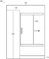
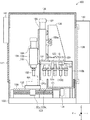
以下、本発明に係る工作機械の一実施形態について図面を参照しながら説明する。図1は、本発明に係る工作機械100の主要部の構成を模式的に示した側面断面図である。また、図2は、図1に示す2−2線から見た工作機械100の全構成の概略を模式的に示す正面断面図である。また、図3は、図1に示す工作機械100の全体構成の概略を模式的に示す背面図である。また、図4は、図1に示す工作機械100の作動を制御するための制御システムのブロック図である。なお、本明細書において参照する図は、本発明の理解を容易にするために一部の構成要素を誇張して表わすなど模式的に表している。このため、各構成要素間の寸法や比率などは異なっていることがある。この工作機械100は、コンピュータ制御(NC制御)によって被加工物WKに対して機械加工(例えば、切削、穴開け、フライス削り、中ぐりなど)を行う機械装置である。
(Configuration of machine tool 100)
Hereinafter, an embodiment of a machine tool according to the present invention will be described with reference to the drawings. FIG. 1 is a side sectional view schematically showing a configuration of a main part of a
工作機械100は、加工ヘッド101を備えている。加工ヘッド101は、被加工物WKに対して切削加工を行う加工工具102を着脱自在に保持するとともに保持した加工工具102を回転駆動する機械装置である。加工工具102は、被加工物WKに対して切削加工を行うフライス、エンドミル、ドリルまたはタップなどの金属加工用の刃物である。この加工ヘッド101は、主として、スピンドル103、スピンドル駆動モータ104およびヘッド本体部105をそれぞれ備えて構成されている。
The
スピンドル103は、加工工具102を着脱自在に保持する図示しないツールチャックを内蔵してスピンドル駆動モータ104によって回転駆動する金属製の軸状部品である。スピンドル駆動モータ104は、後述するNC制御装置140によって作動が制御されるアクチュエータである。ヘッド本体部105は、スピンドル103およびスピンドル駆動モータ104をそれぞれ支持する金属製の構造体である。この加工ヘッド101は、ヘッド本体部105を介してヘッド支持体106に支持されている。
The
ヘッド支持体106は、ヘッド本体部105を図示上下方向であるZ軸方向に変位可能な状態で支持する金属製の構造体であり、主としてZ軸方向に延びて形成されている。このヘッド支持体106は、ヘッド本体部105をZ軸方向に変位させるための図示しない送りネジ機構およびこの送りネジ機構を駆動するためのZ軸駆動モータ107をそれぞれ備えている。この場合、送りネジ機構とは、軸状体の外周面に雄ネジが形成されたネジ軸(図示せず)とこの雄ネジに噛み合う雌ネジが形成された可動体(図示せず)とで構成されており、ネジ軸を回転駆動させることにより可動体をネジ軸の軸線方向に沿って直線的に駆動させる機械装置である。Z軸駆動モータ107は、NC制御装置140によって作動が制御されるアクチュエータである。このヘッド支持体106は、コラム108に支持されている。
The
コラム108は、ヘッド支持体106をZ軸方向に直交する図1の紙面に対して垂直方向(図2において左右方向)であるX軸方向に変位可能な状態で支持する金属製の構造体であり、主としてX軸方向に延びて形成されている。このコラム108は、主として、ヘッド支持体106をX軸方向に変位させるための送りネジ機構109aおよびこの送りネジ機構109aを駆動するためのX軸駆動モータ109bをそれぞれ備えている。X軸駆動モータ109bは、NC制御装置140によって作動が制御されるアクチュエータである。このコラム108は、2つのコラムベース110a,110bにそれぞれ支持されている。
The
コラムベース110a,110bは、コラム108を固定的に支持するとともにツールマガジンユニット120をZ軸方向およびX軸方向にそれぞれ直交する図1の左右方向であるY軸方向に変位可能な状態で支持する左右一対の金属製の構造体であり、主としてZ軸方向およびY軸方向にそれぞれ延びる柱状に形成されている。すなわち、工作機械100は、2つのコラムベース110a,110b上にコラム108が架設された所謂門型で構成されている。これら2つのコラムベース110a,110bの各上端部には、ツールマガジンユニット120が支持されている。
The column bases 110a and 110b support the
ツールマガジンユニット120は、加工ヘッド101が使用する加工工具102を複数保持することができる機械装置であり、主として、可動支持ベース121、マガジンカバー124およびツールマガジン125をそれぞれ備えている。可動支持ベース121は、マガジンカバー124およびツールマガジン125を支持する金属製の部品であり、図示下方から上方に向かって広がる空洞の錐体状に形成されるとともに同錐体の上端部がフランジ状に張り出して形成されている。この可動支持ベース121は、フランジ状に張り出した上端部が2つのコラムベース110a,110b間にY軸方向に沿って摺動自在な状態で架設されている。
The
そして、この可動支持ベース121には、ツールマガジン125をY軸方向に変位させるための図示しない送りネジ機構、この送りネジ機構を駆動するためのマガジン駆動モータ122、およびツールマガジン125を回転駆動するための割出駆動モータ123をそれぞれ備えている。マガジン駆動モータ122および割出駆動モータ123は、NC制御装置140によってそれぞれ作動が制御されるアクチュエータである。また、可動支持ベース121には、マガジンカバー124が設けられている。
The
マガジンカバー124は、被加工物WKの加工によって飛散する切粉や切削油などの飛散物のツールマガジン125への飛来を防止するための板状の部品であり、後述するワークテーブル132とツールマガジン125との間で可動支持ベース121から下垂した状態で設けられている。このマガジンカバー124は、NC制御装置140によって作動制御されるエアシリンダ124aによってX軸方向に開閉可能な左右2つで一対を構成するスライドドア124bをそれぞれ備えている。
ツールマガジン125は、加工ヘッド101に対して受け渡しする加工工具102を着脱自在に保持する機械装置であり、複数の加工工具102を1つずつ保持するチャックが円周方向に複数配置されて構成されている。このツールマガジン125は、可動支持ベース121内に設けられた割出駆動モータ123に連結された状態で可動支持ベース121の下面から下垂して設けられている。
The
そして、これらの2つのコラムベース110a,110bは、基台130上に起立した状態で取り付けられている。基台130は、工作機械100の各構成部品および各種機器を支持する土台となる金属製の構造体であり、主としてY軸方向に延びて形成されている。この基台130には、コラム108の下方に受け板131が設けられるとともに加工ヘッド101の下方にワークテーブル132が設けられる。受け板131は、ツールマガジン125の下方における工作機械100の部品や機器の汚損を防止するための金属製の板状部品である。
These two
ワークテーブル132は、被加工物WKを着脱自在に保持する金属製の板状部材であり、X軸方向およびY軸方向に延びる平面視方形状に形成されている。このワークテーブル132は、送りネジ機構133およびY軸駆動モータ134によって加工ヘッド101に対してY軸方向に変位可能な状態で支持されている。送りネジ機構133は、軸状体の外周面に雄ネジが形成されたネジ軸133aとこの雄ネジに噛み合う雌ネジが形成された可動体133bとで構成されており、ネジ軸133aを回転駆動させることにより可動体133bが設けられたワークテーブル132をネジ軸133aの軸線方向、すなわちY軸方向に沿って直線的に駆動させる機械装置である。Y軸駆動モータ134は、NC制御装置140によって作動が制御されるアクチュエータである。また、ワークテーブル132と送りネジ機構133との間には、送りネジ機構133への飛散物の飛来を防止するための蛇腹状の底部カバー135が設けられている。
The work table 132 is a metal plate-like member that detachably holds the workpiece WK, and is formed in a planar view shape extending in the X-axis direction and the Y-axis direction. The work table 132 is supported by the
基台130の周囲には外装カバー136が設けられている。外装カバー136は、加工ヘッド101、コラム108およびワークテーブル132などを四方および上方を覆って工作機械100の筐体を構成する金属製の板状部品である。この外装カバー136には、工作機械100の前面となる面に前面開口部137が形成されるとともに、工作機械100の背面となる面にマガジン開口部138が形成されている。前面開口部137は、作業者がワークテーブル132に対して作業を行なったり、工作機械100のメンテナンスを行うために開閉する部分であり、両開きのスライドドアによって構成されている。また、マガジン開口部138は、作業者がツールマガジン125に対して作業を行なったり、工作機械100のメンテナンスを行うために開閉する部分であり、図3において破線矢印に示すように、開閉可能なスライドドアによって構成されている。
An
また、外装カバー136における背面には、NC制御装置140が設けられている。NC制御装置140は、CPU、ROM、RAMなどからなるマイクロコンピュータによって構成されており、工作機械100の全体の作動を総合的に制御するとともに、作業者によって用意される図示しない加工プログラム(所謂NC(Numerical Control)プログラム)に従ってスピンドル駆動モータ104、Z軸駆動モータ107、X軸駆動モータ109b、マガジン駆動モータ122、割出駆動モータ123、エアシリンダ124aおよびY軸駆動モータ134の各作動を制御して被加工物WKに対して加工ヘッド101を相対変位させることにより被加工物WKへの切削加工を制御する。また、このNC制御装置140には、NC制御装置140に対して作業者からの指示を入力するとともにNC制御装置140の作動状況を表示する液晶表示装置を備えた操作パネル141を備えている。この操作パネル141は、外装カバー136の前面に設けられている。
An
(工作機械100の作動)
次に、上記のように構成した工作機械100の作動について説明する。まず、作業者は、工作機械100の電源をONにする。これにより、工作機械100は、NC制御装置140内のROMに予め記憶されている図示しない所定の制御プログラムを実行することにより、加工ヘッド101を原点復帰させた後、作業者からの指示を待つ待機状態となる。
(Operation of machine tool 100)
Next, the operation of the
次に、作業者は、工作機械100のワークテーブル132上に被加工物WKをセットするとともに、この被加工物WKの加工に必要な加工工具102をツールマガジン125にセットする。この場合、作業者は、工作機械100の前面開口部137を開くことによりこの前面開口部137を介して被加工物WKをワークテーブル132にセットするとともに、マガジン開口部138を介して複数の加工工具102をそれぞれツールマガジン125にセットする
Next, the operator sets the workpiece WK on the work table 132 of the
次に、作業者は、被加工物WKに対して3次元的に切削加工するための加工プログラム(NCプログラム)をNC制御装置140に入力した後、この加工プログラムの実行をNC制御装置140に指示する。この場合、被加工物WKに対して3次元的な切削加工を行うための加工プログラムには、加工内容に応じた加工工具102を選択して加工ヘッド101に対して工具交換を行う指令、すなわち、マガジン駆動モータ122、割出駆動モータ123およびエアシリンダ124aの作動を制御する指令が含まれている。
Next, the operator inputs a machining program (NC program) for three-dimensionally cutting the workpiece WK to the
この指示に応答して、NC制御装置140は、スピンドル駆動モータ104、Z軸駆動モータ107、X軸駆動モータ109b、マガジン駆動モータ122、割出駆動モータ123、エアシリンダ124aおよびY軸駆動モータ134の各作動を制御することにより被加工物WKに対する加工ヘッド101が保持する加工工具102の先端部(刃先)の位置を変化させる。これにより、ワークテーブル132上に保持された被加工物WKは、加工工具102によって3次元的に切削加工される。
In response to this instruction, the
この被加工物WKに対する切削加工においては、NC制御装置140は、被加工物WKの加工状況に応じてツールマガジンユニット120を変位させる。以下に典型的なツールマガジンユニット120の変位態様例1,2をそれぞれ示す。なお、以下の変形態様例においては、ツールマガジンユニット120の待機位置とは加工中の加工工具102、被加工物WKおよびワークテーブル132がそれぞれツールマガジンユニット120に接触しない位置(例えば、工作機械100におけるY軸方向の最奥端位置(図1参照))であり、工具交換位置とは加工ヘッド101がX軸方向中央部に位置した状態で加工ヘッド101の真下の位置にツールマガジン125における最前部のチャックを位置させる位置であり(図5参照)、ワークテーブル132の退避位置とは工作機械100におけるY軸方向の最前端である(図5参照)。
In cutting the workpiece WK, the
(変位態様例1)
NC制御装置140は、加工ヘッド101に対する加工工具102の工具交換時にワークテーブル132の変位とともにツールマガジンユニット120を変位させることができる。具体的には、NC制御装置140は、図5に示すように、加工ヘッド101に対して工具交換を行う際、ワークテーブル132の退避位置への変位と同時にツールマガジンユニット120を待機位置から前進させて工具交換位置に位置決めすることができる。また、NC制御装置140は、加工ヘッド101に対して工具交換を行った後、ワークテーブル132を退避位置から加工位置に復帰させる変位と同時にツールマガジンユニット120を工具交換位置から待機位置に後退させることができる。これらによれば、工作機械100は、ワークテーブル132の変位の完了の後にツールマガジンユニット120を変位させる場合に比べて早期に工具交換処理を終えることができる。
(Displacement example 1)
The
なお、加工ヘッド101における工具交換処理は、NC制御装置140が以下のサブステップ1〜7を実行することによって行われる。
サブステップ1:NC制御装置140は、加工ヘッド101を工具交換可能なZ軸方向の位置に位置決めする。
サブステップ2:NC制御装置140は、加工ヘッド101が保持する加工工具102を掴むツールマガジン125におけるチャックを割り出す。
サブステップ3:NC制御装置140は、ツールマガジンユニット120を工具交換位置に位置決めしてツールマガジン125によって加工工具102を把持させる。
サブステップ4:NC制御装置140は、加工ヘッド101をZ軸方向に上昇させて加工工具102を加工ヘッド101から抜く。
サブステップ5:NC制御装置140は、加工ヘッド101が新たに保持する加工工具102を保持するツールマガジン125のチャックを割り出す。
サブステップ6:NC制御装置140は、加工ヘッド101をZ軸方向に下降させて新たな加工工具102を加工ヘッド101に保持させる。
サブステップ7:NC制御装置140は、ツールマガジンユニット120を退避させる。
The tool change process in the
Substep 1: The
Substep 2: The
Substep 3: The
Substep 4: The
Sub-step 5: The
Substep 6: The
Substep 7: The
そして、この工具交換処理においては、NC制御装置140は、ツールマガジンユニット120を加工ヘッド101側に変位させる際、加工ヘッド101とマガジンカバー124との間隔が所定量に達したときにエアシリンダ124aの作動を制御することにより左右一対のスライドドア124bを開いて加工ヘッド101がマガジンカバー124を通過できるようにする。また、NC制御装置140は、工具交換処理後においては、ツールマガジンユニット120を加工ヘッド101から離隔させる際、加工ヘッド101とマガジンカバー124との間隔が所定量以上に達したときにエアシリンダ124aの作動を制御することによりスライドドア124bを閉じて加工によって生じる飛散物がツールマガジン125に飛散しないようにする。なお、割出駆動モータ123の駆動によるツールマガジン125における加工工具102を保持するチャックの選択は、ツールマガジンユニット120の変位の前または変位中に行うことができる。
In this tool change process, when the
このような、ワークテーブル132の変位に同期したツールマガジンユニット120を変位は、加工プログラムにマガジン駆動モータ122、割出駆動モータ123およびエアシリンダ124aの各作動を制御する指令を含ませておくことで実現できる。なお、この場合、NC制御装置140は、ツールマガジンユニット120の変位速度をワークテーブル132の相対位置に応じて変化させることができる。例えば、NC制御装置140は、ワークテーブル132とツールマガジンユニット120とのY軸方向での間隔が所定の間隔以上に離れている場合にはツールマガジンユニット120を早送りするとともに前記間隔が所定の間隔未満の場合にはツールマガジンユニット120の変位速度をワークテーブル132の変位速度以下にすることができる。
For such displacement of the
(変位態様例2)
NC制御装置140は、被加工物WKの加工中における位置に応じた待機位置にツールマガジンユニット120を位置決めすることができる。具体的には、NC制御装置140は、図6に示すように、被加工物WKの加工中における被加工物WKおよびワークテーブル132に接触しない領域における最も被加工物WKまたはワークテーブル132に近い位置を待機位置としてツールマガジンユニット120を位置決めする。この場合、ツールマガジンユニット120の待機位置は、作業者が予め加工プログラム中に指示しておいてもよいし、NC制御装置140が加工プログラムをコンピュータ上で実行して自動的に算出するようにしてもよい。これらの場合、工作機械100は、被加工物WKに対する加工工程全体でツールマガジンユニット120の待機位置を設定してもよいし、被加工物WKに対する加工工程における加工工具102ごとにツールマガジンユニット120の待機位置を設定してもよい。これによれば、工作機械100は、加工ヘッド101に対して最短距離の待機位置から工具交換処理を行なえるため、早期に工具交換処理を終えることができる。
(Displacement example 2)
The
また、上記各変位態様例1,2においては、工作機械100は、被加工物WKの加工中にツールマガジンユニット120が待機位置に位置する状態でマガジン駆動モータ122および割出駆動モータ123の作動を停止させることにより作業者にツールマガジンユニット120のメンテナンスをさせることができる。この場合、作業者は、ツールマガジンユニット120への動力供給の停止状態においてマガジン開口部138を開口することによってツールマガジンユニット120自体やツールマガジン125が保持する加工工具102のメンテナンスを行うことができる。
Further, in each of the displacement examples 1 and 2 described above, the
上記作動説明からも理解できるように、上記実施形態によれば、工作機械100は、NC制御装置140がツールマガジン125を数値制御により変位させることができるため、加工工具102の交換処理を効率的に行うことができる。
As can be understood from the above operation description, according to the above embodiment, the
さらに、本発明の実施にあたっては、上記実施形態に限定されるものではなく、本発明の目的を逸脱しない限りにおいて種々の変更が可能である。 Furthermore, in carrying out the present invention, the present invention is not limited to the above embodiment, and various modifications can be made without departing from the object of the present invention.
例えば、上記実施形態においては、工作機械100は、加工ヘッド101がワークテーブル132に対してX軸方向およびZ軸方向にそれぞれ変位するとともに、ワークテーブル132が加工ヘッド101に対してY軸方向に変位するように構成されている。すなわち、Z軸駆動モータ107、X軸駆動モータ109bおよびY軸駆動モータ134が本発明に係る加工工具変位手段に相当する。しかし、加工工具変位手段は、加工ヘッド101をワークテーブル132に対して相対的に変位させるよう構成されていれば、必ずしも上記実施形態に限定されるものではない。したがって、工作機械100は、加工ヘッド101をワークテーブル132に対してX軸方向、Y軸方向およびZ軸方向に変位させるように構成することもできるとともに、ワークテーブル132を加工ヘッド101に対してX軸方向、Y軸方向およびZ軸方向に変位させるように構成することもできる。
For example, in the embodiment described above, in the
また、上記実施形態においては、工作機械100は、ツールマガジンユニット120が加工ヘッド101に対してY軸方向に変位するように構成されている。すなわち、マガジン駆動モータ122が本発明に係るマガジン変位手段に相当する。しかし、マガジン変位手段は、ツールマガジン125を加工ヘッド101に対して相対的に変位させるよう構成されていれば、必ずしも上記実施形態に限定されるものではない。したがって、工作機械100は、加工ヘッド101をツールマガジン125に対してY軸方向、さらには、X軸方向およびZ軸方向に変位させるように構成することもできる。
In the above embodiment, the
また、上記実施形態においては、ツールマガジンユニット120は、マガジンカバー124を備えて構成されている。しかし、マガジンカバー124は、ツールマガジン125およびツールマガジン125が保持する加工工具102への飛散物の飛来を防止するためのものであり、これらへの飛散物の飛来が許容される場合には不要である。また、上記実施形態においては、マガジンカバー124は、ツールマガジンユニット120に設けてツールマガジン125と一体的に変位するように構成した。しかし、マガジンカバー124は、ツールマガジン125とは別体、例えば、コラム108に固定的に設けることもできる。
In the above embodiment, the
また、上記実施形態においては、外装カバー136における背面にマガジン開口部138を設けた。しかし、マガジン開口部138は、ツールマガジン125にアクセスできる位置、換言すれば、ツールマガジン125の周囲のうちのワークテーブル132に対向する側以外の壁面に形成されていれば、必ずしも上記実施形態に限定されるものではない。したがって、マガジン開口部138は、例えば、外装カバー136における左右の側面の少なくとも一方に設けることもできる。また、マガジン開口部138は、ツールマガジン125へのアクセスが不要の場合には、省略することもできる。
In the above embodiment, the
WK…被加工物、
100…工作機械、
101…加工ヘッド、102…加工工具、103…スピンドル、104…スピンドル駆動モータ、105…ヘッド本体部、106…ヘッド支持体、107…Z軸駆動モータ、108…コラム、109a…送りネジ機構、109b…X軸駆動モータ、110a,110b…コラムベース、
120…ツールマガジンユニット、121…可動支持ベース、122…マガジン駆動モータ、123…割出駆動モータ、124…マガジンカバー、124a…エアシリンダ、124b…スライドドア、125…ツールマガジン、
130…基台、131…受け板、132…ワークテーブル、133…送りネジ機構、133a…ネジ軸、133b…可動体、134…Y軸駆動モータ、135…底部カバー、136…外装カバー、137…前面開口部、138…マガジン開口部、
140…NC制御装置、141…操作パネル。
WK ... Workpiece,
100 ... Machine tool,
DESCRIPTION OF
DESCRIPTION OF
DESCRIPTION OF
140: NC control device, 141: Operation panel.
Claims (5)
前記被加工物を加工する加工工具を着脱自在に保持する加工ヘッドと、
前記加工ヘッドを前記ワークテーブルに対して相対的に変位させる加工工具変位手段と、
前記加工ヘッドが保持する前記加工工具を複数着脱自在に保持することができるツールマガジンと、
前記ツールマガジンを前記加工ヘッドに対して相対的に変位させるマガジン変位手段と、
前記ワークテーブルと前記ツールマガジンとの間に開閉自在に設けられて前記ツールマガジンが保持する前記加工工具への飛散物を阻止するマガジンカバーと、
前記マガジンカバーを開閉するマガジンカバー開閉手段と、
前記加工工具変位手段および前記マガジン変位手段をそれぞれ数値制御して前記加工ヘッドおよび前記ツールマガジンを相対変位させるNC制御装置とを備え、
前記マガジンカバーは、
前記ツールマガジンに設けられて同ツールマガジンと一体的に変位するものであり、
前記NC制御装置は、
前記開閉手段の作動を制御して前記マガジンカバーを開閉することを特徴とする工作機械。 A work table for detachably holding a workpiece;
A machining head for detachably holding a machining tool for machining the workpiece;
Machining tool displacing means for displacing the machining head relative to the work table;
A tool magazine capable of detachably holding a plurality of the processing tools held by the processing head;
Magazine displacing means for displacing the tool magazine relative to the machining head;
A magazine cover that is provided between the work table and the tool magazine so as to be freely opened and closed, and prevents scattered matter on the processing tool held by the tool magazine;
Magazine cover opening and closing means for opening and closing the magazine cover;
An NC control unit that controls the machining tool displacement means and the magazine displacement means numerically to relatively displace the machining head and the tool magazine ,
The magazine cover is
It is provided in the tool magazine and is displaced integrally with the tool magazine,
The NC control device
A machine tool that controls the operation of the opening / closing means to open and close the magazine cover .
前記NC制御装置は、
前記ワークテーブルとの相対的な位置に応じて前記マガジン変位手段の作動を制御して前記ツールマガジンの位置決めを行うことを特徴とする工作機械。 In the machine tool according to claim 1,
The NC control device
A machine tool for positioning the tool magazine by controlling the operation of the magazine displacing means according to a relative position with respect to the work table.
前記NC制御装置は、
前記加工ヘッドに対して前記加工工具の交換処理を行う場合に前記ワークテーブルの変位と同時に前記ツールマガジンを変位させることを特徴とする工作機械。 In the machine tool according to claim 1 or 2,
The NC control device
A machine tool, wherein the tool magazine is displaced simultaneously with the displacement of the work table when the machining tool is exchanged with respect to the machining head.
前記ワークテーブルおよび前記ツールマガジンの周囲を囲む外装カバーを備え、
前記外装カバーは、
前記ツールマガジンの周囲のうちの前記ワークテーブルに対向する側以外の壁面に開閉自在のマガジン開口部が設けられていることを特徴とする工作機械。 The machine tool according to any one of claims 1 to 3, further comprising:
An exterior cover surrounding the work table and the tool magazine;
The exterior cover is
Wherein said magazine opening opened and closed on the wall surface other than the side facing the work table of the surrounding tool magazine provided a machine tool according to claim Rukoto.
前記被加工物を加工する加工工具を着脱自在に保持する加工ヘッドと、
前記加工ヘッドを前記ワークテーブルに対して相対的に変位させる加工工具変位手段と、
前記加工ヘッドが保持する前記加工工具を複数着脱自在に保持することができるツールマガジンと、
前記ツールマガジンを前記加工ヘッドに対して相対的に変位させるマガジン変位手段と、
前記ワークテーブルおよび前記ツールマガジンの周囲を囲む外装カバーと、
前記加工工具変位手段および前記マガジン変位手段をそれぞれ数値制御して前記加工ヘッドおよび前記ツールマガジンを相対変位させるNC制御装置とを備え、
前記外装カバーは、
前記ツールマガジンの周囲のうちの前記ワークテーブルに対向する側以外の壁面に前記ツールマガジンに面してアクセス可能な開閉自在のマガジン開口部が設けられていることを特徴とする工作機械。
A work table for detachably holding a workpiece;
A machining head for detachably holding a machining tool for machining the workpiece;
Machining tool displacing means for displacing the machining head relative to the work table;
A tool magazine capable of detachably holding a plurality of the processing tools held by the processing head;
Magazine displacing means for displacing the tool magazine relative to the machining head;
An exterior cover surrounding the work table and the tool magazine;
An NC control unit that controls the machining tool displacement means and the magazine displacement means numerically to relatively displace the machining head and the tool magazine,
The exterior cover is
Machine tool characterized that you have the access facing the tool magazine can be freely opened and closed the magazine opening is provided on the wall surface other than the side facing the work table of the periphery of the tool magazine.
Priority Applications (3)
| Application Number | Priority Date | Filing Date | Title |
|---|---|---|---|
| JP2014104052A JP6376440B2 (en) | 2014-05-20 | 2014-05-20 | Machine Tools |
| PCT/JP2015/059076 WO2015178096A1 (en) | 2014-05-20 | 2015-03-25 | Machine tool |
| DE112015002391.7T DE112015002391T5 (en) | 2014-05-20 | 2015-03-25 | machine tool |
Applications Claiming Priority (1)
| Application Number | Priority Date | Filing Date | Title |
|---|---|---|---|
| JP2014104052A JP6376440B2 (en) | 2014-05-20 | 2014-05-20 | Machine Tools |
Publications (3)
| Publication Number | Publication Date |
|---|---|
| JP2015217492A JP2015217492A (en) | 2015-12-07 |
| JP2015217492A5 JP2015217492A5 (en) | 2017-10-12 |
| JP6376440B2 true JP6376440B2 (en) | 2018-08-22 |
Family
ID=54553773
Family Applications (1)
| Application Number | Title | Priority Date | Filing Date |
|---|---|---|---|
| JP2014104052A Active JP6376440B2 (en) | 2014-05-20 | 2014-05-20 | Machine Tools |
Country Status (3)
| Country | Link |
|---|---|
| JP (1) | JP6376440B2 (en) |
| DE (1) | DE112015002391T5 (en) |
| WO (1) | WO2015178096A1 (en) |
Families Citing this family (8)
| Publication number | Priority date | Publication date | Assignee | Title |
|---|---|---|---|---|
| US10220478B2 (en) * | 2014-08-20 | 2019-03-05 | Fuji Corporation | Machining center |
| JP2018094673A (en) * | 2016-12-13 | 2018-06-21 | ローランドディー.ジー.株式会社 | Processing system and program |
| US10661313B2 (en) | 2017-01-05 | 2020-05-26 | Fives Cinetic Corp. | Multi-tool part cleaning machine |
| JPWO2019151147A1 (en) * | 2018-01-31 | 2021-04-15 | 学校法人慶應義塾 | Machine tools, manufacturing methods and programs |
| JP7248557B2 (en) * | 2019-10-24 | 2023-03-29 | Towa株式会社 | Blade changing device, cutting device, and method for manufacturing cut product |
| WO2021215001A1 (en) * | 2020-04-24 | 2021-10-28 | Dmg森精機株式会社 | Processing machine |
| CN112872430A (en) * | 2021-01-27 | 2021-06-01 | 安庆金野新材料有限公司 | Processing system of high-temperature alloy metal material |
| DE102021125634A1 (en) | 2021-10-04 | 2023-04-06 | Homag Bohrsysteme Gmbh | machine tool and method |
Family Cites Families (10)
| Publication number | Priority date | Publication date | Assignee | Title |
|---|---|---|---|---|
| JPS5840339U (en) * | 1981-09-05 | 1983-03-16 | 株式会社 滝澤鉄工所 | Automatic tool changer in vertical machining center |
| JPS6357039U (en) * | 1986-10-02 | 1988-04-16 | ||
| US5181898A (en) * | 1991-09-16 | 1993-01-26 | Cincinnati Milacron, Inc. | Cover assembly for multi-configurable machine tool |
| JPH07171728A (en) * | 1993-12-17 | 1995-07-11 | Showa Seiko Kk | Device for multi-spindle simultaneous tool changing in machine tool |
| JPH1034473A (en) * | 1996-07-17 | 1998-02-10 | Seiko Seiki Co Ltd | Cnc three-dimensional machining unit |
| JP2004001229A (en) * | 2003-07-29 | 2004-01-08 | Mori Seiki Co Ltd | Nc machine tool |
| JP4443380B2 (en) * | 2004-10-27 | 2010-03-31 | コマツNtc株式会社 | Tool magazine apparatus and vertical machining center equipped with the same |
| JP5575673B2 (en) * | 2011-01-20 | 2014-08-20 | 光洋機械工業株式会社 | Automatic tool changer |
| JP5949182B2 (en) * | 2012-06-05 | 2016-07-06 | ブラザー工業株式会社 | Machine Tools |
| JP2015123575A (en) * | 2013-12-27 | 2015-07-06 | キヤノン電子株式会社 | Machine tool and tool magazine for machine tool |
-
2014
- 2014-05-20 JP JP2014104052A patent/JP6376440B2/en active Active
-
2015
- 2015-03-25 DE DE112015002391.7T patent/DE112015002391T5/en active Pending
- 2015-03-25 WO PCT/JP2015/059076 patent/WO2015178096A1/en active Application Filing
Also Published As
| Publication number | Publication date |
|---|---|
| DE112015002391T5 (en) | 2017-02-09 |
| JP2015217492A (en) | 2015-12-07 |
| WO2015178096A1 (en) | 2015-11-26 |
Similar Documents
| Publication | Publication Date | Title |
|---|---|---|
| JP6376440B2 (en) | Machine Tools | |
| JP2015217492A5 (en) | ||
| JP6604592B2 (en) | Machine Tools | |
| JP5026884B2 (en) | Machine tool with automatic tool changer | |
| TWI763939B (en) | lathe | |
| US20170293288A1 (en) | Control device for machine tool | |
| JP6209568B2 (en) | Machine Tools | |
| TWI767071B (en) | Lathe with tool unit installed | |
| JP2002205209A (en) | Drilling method by three-dimensional cutting | |
| JP2013063488A (en) | Vertical machining center | |
| JP2007094458A (en) | Numerical control device | |
| KR101323890B1 (en) | Turret type vertical lathe and method of control by the same, and bevel gearboxes produced by the same | |
| JP2021102266A (en) | Hole processing machine and method for processing oval hole and inner diameter change hole using hole processing machine | |
| JP2002331433A (en) | Cutting work unit | |
| JP2012161904A (en) | Composite tool, machining method, and machine tool | |
| JP2017007061A (en) | Machining center | |
| JP6754870B1 (en) | Machine tools and control methods | |
| JP7085076B1 (en) | Machine tools, control methods, and control programs | |
| JP2002254408A (en) | Apparatus for cutting door member and the like | |
| CN214080205U (en) | Numerical control drilling, tapping and milling all-in-one machine for precision manufacturing of metal parts | |
| JP6880437B2 (en) | lathe | |
| JP6859719B2 (en) | Machine Tools | |
| JP2024505163A (en) | Assemblies, devices and methods for machining mechanical parts | |
| JPS6158242B2 (en) | ||
| TW202309688A (en) | Machine tool |
Legal Events
| Date | Code | Title | Description |
|---|---|---|---|
| A621 | Written request for application examination |
Free format text: JAPANESE INTERMEDIATE CODE: A621 Effective date: 20170512 |
|
| A521 | Written amendment |
Free format text: JAPANESE INTERMEDIATE CODE: A523 Effective date: 20170831 |
|
| A131 | Notification of reasons for refusal |
Free format text: JAPANESE INTERMEDIATE CODE: A131 Effective date: 20180508 |
|
| A521 | Written amendment |
Free format text: JAPANESE INTERMEDIATE CODE: A523 Effective date: 20180625 |
|
| TRDD | Decision of grant or rejection written | ||
| A01 | Written decision to grant a patent or to grant a registration (utility model) |
Free format text: JAPANESE INTERMEDIATE CODE: A01 Effective date: 20180704 |
|
| A61 | First payment of annual fees (during grant procedure) |
Free format text: JAPANESE INTERMEDIATE CODE: A61 Effective date: 20180712 |
|
| R150 | Certificate of patent or registration of utility model |
Ref document number: 6376440 Country of ref document: JP Free format text: JAPANESE INTERMEDIATE CODE: R150 |
|
| R250 | Receipt of annual fees |
Free format text: JAPANESE INTERMEDIATE CODE: R250 |