JP3699199B2 - Laser processing machine - Google Patents
Laser processing machine Download PDFInfo
- Publication number
- JP3699199B2 JP3699199B2 JP11643096A JP11643096A JP3699199B2 JP 3699199 B2 JP3699199 B2 JP 3699199B2 JP 11643096 A JP11643096 A JP 11643096A JP 11643096 A JP11643096 A JP 11643096A JP 3699199 B2 JP3699199 B2 JP 3699199B2
- Authority
- JP
- Japan
- Prior art keywords
- axis
- axis carriage
- machining
- laser
- unit
- Prior art date
- Legal status (The legal status is an assumption and is not a legal conclusion. Google has not performed a legal analysis and makes no representation as to the accuracy of the status listed.)
- Expired - Lifetime
Links
Images


Landscapes
- Laser Beam Processing (AREA)
Description
【0001】
【発明の属する技術分野】
この発明は、ワークにレーザ加工以外の他の加工も組み合せて行い得るようにしたレーザ加工機に関する。
【0002】
【従来の技術】
従来、一軸加工テーブル移動,一軸光移動タイプのレーザ加工機が知られている。このレーザ加工機ではベッド上にX軸方向へ移動自在な加工テーブルが設けられている。また、前記ベッドに加工機本体フレームが取付けられ、この加工機本体フレームにおける上部フレームにはY軸方向へ移動自在なY軸キャレッジが設けられている。このY軸キャレッジにレーザ加工ヘッドが設けられている。
【0003】
上記構成により、加工テーブル上に加工すべきワークを載置固定せしめた状態で、加工テーブルをX軸方向へ、Y軸キャレッジをY軸方向へ移動せしめると共に、レーザ加工ヘッドからレーザビームをワークへ照射せしめることによってワークにレーザ加工が行われる。
【0004】
ワークにレーザ加工と一緒に例えばパンチ加工,ドリル加工,タップ加工などを加えて複合加工を行う場合には、前記レーザ加工ヘッドによるレーザ加工点と離れた位置に付加加工点を有して行っている。または、レーザ加工ヘッドを設けたY軸キャレッジに付加加工ユニットを設けて複合加工を行うことも知られている。
【0005】
【発明が解決しようとする課題】
ところで、上述した従来のレーザ複合加工機のうち、レーザ加工点と離れた位置に付加加工点を有するレーザ複合加工機では、レーザ加工時の送り軸とは別に独立した送り軸を追加することなり、スペース,価格ともレーザ専用機と比較すると大きく、高価となってしまう。
【0006】
また、Y軸キャレッジにレーザ加工ヘッドの脇へ付加加工ユニットを設けたレーザ複合加工機では、レーザ移動軸に重量が増し、レーザ加工機の高速,高精度を行うことが困難になってしまう。
【0007】
この発明の目的は、レーザ加工以外の他の加工を加えた複合加工を行う際、追加送り軸数を最小限にし、かつ高速,高精度加工なレーザ加工を確保できるようにしたレーザ加工機を提供することにある。
【0008】
【課題を解決するための手段】
上記目的を達成するために請求項1によるこの発明のレーザ加工機は、ベッド上にX軸方向へ移動自在な加工テーブルを設け、前記ベッドに取付けた加工機本体フレームにおける上部フレームにY軸方向へ移動自在なY軸キャレッジを設けると共にこのY軸キャレッジにレーザ加工ヘッドを設けてなるレーザ加工機であって、前記上部フレームの一端側の退避位置に、前記Y軸キャリッジと係脱自在な付加加工ユニットを設けてなることを特徴とするものである。
【0009】
したがって、ワークにレーザ加工のみを行う場合には、付加加工ユニットを加工機本体フレームにおける上部フレームの一端側の退避位置に設けておき、加工テーブルをX軸方向へ、Y軸キャレッジをY軸方向へ移動せしめると共にレーザ加工ヘッドからレーザビームをワークへ向けて照射せしめることにより、ワークにレーザ加工が行われる。
【0010】
ワークにレーザ加工と他の加工の複合加工を行う場合には、Y軸キャレッジを加工機本体フレームにおける上部フレームの一端側へ移動せしめてY軸キャレッジに、退避位置に退避されている付加加工ユニットを係合せしめる。この係合された状態で、加工テーブルをX軸方向へ、Y軸キャレッジをY軸方向へ移動せしめると共に、レーザ加工ヘッドからレーザビームをワークへ向けて照射せしめたり、あるいは付加加工ユニットに設けられた工具例えばドリルまたはタップなどで、ワークに他の加工が行われる。
【0011】
而して、複合加工を行う際に、付加加工ユニットがY軸キャレッジに係合されてY軸方向へ移動されるから、追加送り軸数を最小にして、高速,高精度のレーザ加工が行われる。
【0012】
請求項2によるこの発明のレーザ加工機は、請求項1のレーザ加工機において、前記Y軸キャレッジ,付加加工ユニットのどちらか一方にアクチュエータにより揺動する係合爪を設けると共に、他方にこの係合爪が係合する係合凹部を設けてなることを特徴とするものである。
【0013】
したがって、前記Y軸キャレッジ,付加加工ユニットのどちらか一方に設けられたアクチュエータを作動せしめることにより、係合爪が揺動して他方に設けられた係合凹部に容易にかつ確実に係脱される。
【0014】
請求項3によるこの発明のレーザ加工機は、請求項1,2のレーザ加工機において、前記Y軸キャレッジ,付加加工ユニットのどちらか一方に位置決め部材を設けると共に、他方にこの位置決め部材が入り込む穴を設けてなることを特徴とするものである。
【0015】
したがって、Y軸キャレッジ、付加加工ユニットのどちらか一方に設けられた位置決め部材が他方に設けられた穴に入り込んで正確に位置決めされる。
【0016】
請求項4によるこの発明のレーザ加工機は、請求項1,2,3のレーザ加工機において、前記Y軸キャレッジ,付加加工ユニットのどちらか一方に検出センサを設けると共に他方に被検出部を設けてなることを特徴とすものである。
【0017】
したがって、前記Y軸キャレッジ,付加加工ユニットのどちらか一方に設けられた検出センサと他方に設けられた被検出部との作動で、Y軸キャレッジに付加加工ユニットが係合されたことが検出される。
【0018】
請求項5によるこの発明のレーザ加工機は、請求項1,2,3,4のレーザ加工機において、前記付加加工ユニットにドリル,タップなどの工具を交換自在に備えた工具装置を設けてなることを特徴とするものである。
【0019】
したがって、前記付加加工ユニットに設けられた工具装置にはワークの加工によって工具を交換することができるので種々な加工が行われる。
【0020】
【発明の実施の形態】
以下、この発明の実施の形態の例を図面に基いて詳細に説明する。
【0021】
図1,図2および図3を参照するに、レーザ加工機1は、立設されたベッド3を備えており、このベッド3上にはX軸方向へ延伸したガイドレール5が敷設されている。このガイドレール5には複数のスライダを介して加工テーブル7が図示省略のX軸送り機構によりX軸方向へ移動可能に設けられている。この加工テーブル7上に加工すべきワークWが載置されて固定される。
【0022】
前記ベッド3上には加工機本体フレームとしての例えば門型フレーム9が上方へ向けて取付けられており、この門型フレーム9における上部フレーム9Uの前面にはY軸方向へ延伸した複数のガイドレール11が敷設されている。この各ガイドレール11には複数のスライダ13を介してY軸キャレッジ15が図示省略のY軸送り機構によりY軸方向へ移動可能に設けられている。
【0023】
このY軸キャレッジ15にはZ軸キャレッジ17が図示省略のZ軸送り機構によりZ軸方向へ移動可能に設けられており、このZ軸キャリッジ17にはレーザ加工ヘッド19が設けられている。
【0024】
上記構成により、加工すべきワークWを載置した加工テーブル7がX軸送り機構によりガイドレール5に案内されてX軸方向へ移動される。またY軸キャレッジ15がY軸機構によりガイドレール11に案内されてY軸方向へ移動される。さらにZ軸キャリッジ17がZ軸送り機構によりZ軸方向へ移動される。
【0025】
而して、加工テーブル5がX軸方向へ、Y軸キャレッジ15がY軸方向へ、およびZ軸キャレッジ17がZ軸方向へ移動されることにより、加工テーブル5上に載置されたワークWにレーザ加工ヘッド19からレーザビームを照射せしめることにより、所望のレーザ加工が行われることになる。
【0026】
前記上部フレーム9Uの一端側例えば図1において左端側である退避位置には付加加工ユニットとしてのW軸ユニット21が常に退避されている。このW軸ユニット21は複数のスライダ23を介して前記ガイドレール11にY軸方向へ移動可能に設けられている。しかも、前記W軸ユニット21には工具装置としての例えばスピンドルユニット25がW軸方向へ移動可能に設けられている。このスピンドルユニット25には工具としての例えば回転可能なドリル27が装着されている。
【0027】
前記W軸ユニット21とY軸キャレッジ15のオフセット値は例えば200mmあり、Y軸のストロークは例えば加工範囲1270mmに対して200mmだけ反原点側へ移動できるようになっている。
【0028】
上記構成により、加工テーブル7上にあるワークWに例えばレーザ加工とドリル加工を行う際には、Y軸キャレッジ15を図1において左側へ移動せしめて退避位置に退避しているW軸ユニット21をY軸キャレッジ15に係合せしめた後、一緒にY軸方向へ移動せしめることにより行われるものである。
【0029】
前記Y軸キャレッジ15にW軸ユニット21を係脱せしるために、図4に示されているように、Y軸キャリッジ15,W軸ユニット21のどちらか一方例えばY軸キャレッジ15の上下に係合爪29が枢支ピン31を介して枢支されている。また、Y軸キャリッジ15の上下にはアクチュエータとしてのエアシリンダ33の後部がブラケット35を介して取付けられている。前記エアシリンダ33に装着されたピストンロッド37の先端が前記係合爪29の一端に取付けられている。
【0030】
また、前記Y軸キャレッジ15には位置決め部材としての例えば位置決めピン39が複数設けられていると共に、検出センサとしての例えばリミットスイッチ41が複数設けられている。
【0031】
一方、前記Z軸ユニット21の図4において右側における上下には、前記係合爪29が係合する係合凹部43が設けられている。また、Z軸ユニット21の図4において右側面には前記位置決めピン39が位置決めされる穴としての例えばブッシュ45と、前記リミットスイッチ41が当接する被検出部としての例えばドグ47が設けられている。
【0032】
上記構成により、Y軸キャレッジ15にW軸ユニット21を係合せしめるには、図4においてY軸キャリッジ15を左側へ移動せしめると、図5に示されているように、位置決めピン39がブッシュ45内に入り込むと共にリミットスイッチ41がドグ47に当接してY軸キャレッジ15がW軸ユニット21に連結されたことが検出される。すると、エアシリンダ33が作動してピストンロッド37が伸びることにより、各係合爪29が図5においてそれぞれ枢支ピン31を支点として回動し、係合爪29が係合凹部43に係合されることにより、Y軸キャレッジ15にW軸ユニット21が確実に係合せしめることができる。
【0033】
Y軸キャリッジ15からW軸ユニット21を脱するには、エアシリンダ33の作動で係合爪31を係合凹部43より外すと共にY軸キャレッジ15を図5において右側へ移動せしめることにより、位置決めピン39がブッシュ45から抜けると共にリミットスイッチ41がドグ47から離れることにより、Y軸キャリッジ15がW軸ユニット21より脱することになる。
【0034】
ワークWにレーザ加工のみを行う際には、図6に示されているように、W軸ユニット21を上部フレーム9Uの左端側における退避位置に退避せしめる。すなわち、Y軸原点位置より外側に位置しており、レーザ加工ヘッド19のみ軸移動してレーザ加工機単体と全く同じ機能を果す。
【0035】
ワークWに複数加工を行う際には、図7に示されているように、Y軸キャレッジ15を左側へ移動せしめ、Y軸の原点位置にくると、上述したようにY軸キャレッジ15にW軸ユニット21が係合される。そして係合した状態でY軸方向へ移動せしめことにより複合加工を行うことができる。複合加工中に万一Y軸キャレッジ15からW軸ユニット21が外された場合にはリミットスイッチ41がドグ47が離れることで検出することができる。
【0036】
W軸ユニット21とY軸キャレッジ15のオフセット量を予めNC装置に入力しておけば、付加軸での加工はMコード等で指令されたY軸指令で自動的にオフセット量を配慮して位置決めを行うことができる。
【0037】
前記Y軸キャレッジ15とW軸ユニット21とが別体となっており、レーザ加工時はレーザ加工ヘッド19のみ制御,移動させるから、軽量であり高速,高精度なレーザ加工を行うことができる。複合加工時にはW軸ユニット21がY軸キャレッジ15に係合され、レーザ加工時と同一の制御軸で制御することができ、単純な機構となりコストを軽減させることができる。
【0038】
なお、この発明は、前述した実施の形態の例に限定されることなく、適宜な変更を行うことにより、その他の態様で実施し得るものである。本実施の形態の例では工具装置してスピンドルユニットを用い、工具としてドリルの例で説明したが、タップなどその他の工具を用いるようにしてもよい。また、位置め部材,穴として位置決めピン39,ブッシュ45を用いて説明したがそれ以外のものでも構わない。さらに検出センサ,被検出部としてリミットスイッチ41,ドグ47を用いて説明したがそれ以外でもよい。係脱手段として係合爪29,係合凹部43で説明したがそれ以外でもよい。
【0039】
リミットスイッチ41をドグ47に当接せしめる際、自動的にエアブローでその付近を清掃するとさらによいものである。
【0040】
【発明の効果】
以上のごとき実施の形態の説明から理解されるように、請求項1の発明によれば、ワークにレーザ加工のみを行う場合には、付加加工ユニットを加工機本体フレームにおける上部フレームの一端側の退避位置に設けておき、加工テーブルをX軸方向へ、Y軸キャレッジをY軸方向へ移動せしめると共にレーザ加工ヘッドからレーザビームをワークへ向けて照射せしめることにより、ワークにレーザ加工が行われる。
【0041】
ワークにレーザ加工と他の加工の複合加工を行う場合には、Y軸キャレッジを加工機本体フレームにおける上部フレームの一端側へ移動せしめてY軸キャレッジに退避位置に退避されている付加加工ユニットを係合せしめる。この係合された状態で、加工テーブルをX軸方向へ,Y軸キャレッジをY軸方向へ移動せしめると共に、レーザ加工ヘッドからレーザビームをワークへ向けて照射せしめたり、あるいは付加加工ユニットに設けられた工具例えばドリルまたはタップなどで、ワークに他の加工が行われる。
【0042】
而して、複合加工を行う際に、付加加工ユニットがY軸キャレッジに係合されてY軸方向へ移動されるから、追加送り軸数を最小にして、高速,高精度のレーザ加工を行うことができる。
【0043】
請求項2の発明によれば、前記Y軸キャレッジ,付加加工ユニットのどちらか一方に設けられたアクチュエータを作動せしめることにより、係合爪が揺動して他方に設けられた係合凹部に容易にかつ確実に係脱させることができる。
【0044】
請求項3の発明によれば、前記Y軸キャレッジ,付加加工ユニットのどちらか一方に設けられた位置決め部材が他方に設けられた穴に入り込んで正確に位置決めさせることができる。
【0045】
請求項4の発明によれば、前記Y軸キャレッジ,付加加工ユニットのどちらか一方に設けられた検出センサと他方に設けられた被検出部との作動で、Y軸キャレッジに付加加工ユニットが係合されたことを検出させることができる。
【0046】
請求項5の発明によれば、前記付加工ユニットに設けられた工具装置にはワークの加工によって工具を交換することができるので種々な加工を行うことができる。
【図面の簡単な説明】
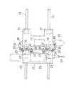
【図1】この発明を実施する一実施の形態の例のレーザ加工機の側面図である。
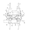
【図2】図1における正面図である。
【図3】図1における平面図である。
【図4】Y軸キャレッジとW軸ユニットを係脱せしめる係脱機構を説明する拡大図である。
【図5】Y軸キャレッジにW軸ユニットを係脱せしめる動作説明図である。
【図6】レーザ加工のみを行う動作を説明する説明図である。
【図7】複合加工を行う動作を説明する説明図である。
【符号の説明】
1 レーザ加工機
3 ベッド
7 加工テーブル
9 門型フレーム(加工機本体フレーム)
9U 上部フレーム
11 ガイドレール
15 軸キャレッジ
17 Z軸キャレッジ
19 レーザ加工ヘッド
21 W軸ユニット(付加加工ユニット)
25 スピンドルユニット(工具装置)
27 ドリル(工具)
29 係合爪
33 エアシリンダ(アクチュエータ)
39 位置決めヒン(位置決め部材)
41 リミットスイッチ(検出センサ)
43 係合凹部
45 ブッシュ(穴)
47 ドグ(被検出部)[0001]
BACKGROUND OF THE INVENTION
The present invention relates to a laser beam machine capable of performing a workpiece other than laser beam machining in combination.
[0002]
[Prior art]
Conventionally, laser processing machines of the uniaxial machining table movement type and the uniaxial optical movement type are known. In this laser processing machine, a processing table that is movable in the X-axis direction is provided on a bed. Further, a processing machine main body frame is attached to the bed, and an upper axis of the processing machine main body frame is provided with a Y-axis carriage that is movable in the Y-axis direction. A laser processing head is provided on the Y-axis carriage.
[0003]
With the above configuration, with the workpiece to be machined placed on the machining table, the machining table is moved in the X-axis direction, the Y-axis carriage is moved in the Y-axis direction, and the laser beam is transferred from the laser machining head to the workpiece. Laser processing is performed on the workpiece by irradiating.
[0004]
For example, when a workpiece is subjected to combined machining by adding, for example, punching, drilling, or tapping together with laser machining, an additional machining point should be provided at a position away from the laser machining point by the laser machining head. Yes. Alternatively, it is also known to perform complex machining by providing an additional machining unit on a Y-axis carriage provided with a laser machining head.
[0005]
[Problems to be solved by the invention]
By the way, among the above-mentioned conventional laser processing machines, in a laser processing machine having an additional processing point at a position distant from the laser processing point, an independent feed axis is added separately from the feed axis at the time of laser processing. The space and price are large and expensive compared to laser dedicated machines.
[0006]
Further, in a laser combined processing machine in which an additional processing unit is provided on the Y-axis carriage on the side of the laser processing head, the weight of the laser moving shaft increases, making it difficult to achieve high speed and high accuracy of the laser processing machine.
[0007]
An object of the present invention is to provide a laser processing machine capable of minimizing the number of additional feed axes and ensuring high-speed, high-precision laser processing when performing composite processing with processing other than laser processing. It is to provide.
[0008]
[Means for Solving the Problems]
In order to achieve the above object, according to a first aspect of the present invention, there is provided a laser processing machine according to the present invention, wherein a processing table movable in the X-axis direction is provided on a bed, and an upper frame of a processing machine body frame attached to the bed A laser processing machine having a Y-axis carriage movable to the Y-axis carriage and a laser processing head provided on the Y-axis carriage, and is detachably attached to the Y-axis carriage at a retracted position on one end side of the upper frame. A machining unit is provided.
[0009]
Therefore, when only laser machining is performed on the workpiece, an additional machining unit is provided at the retreat position on one end side of the upper frame in the machine body frame, the machining table is in the X axis direction, and the Y axis carriage is in the Y axis direction. The workpiece is subjected to laser machining by irradiating the workpiece with a laser beam from the laser machining head.
[0010]
When performing combined processing of laser processing and other processing on the workpiece, the Y-axis carriage is moved to one end side of the upper frame in the machine body frame, and the additional processing unit is retracted to the Y-axis carriage at the retracted position. Engage. In this engaged state, the machining table is moved in the X-axis direction, the Y-axis carriage is moved in the Y-axis direction, and a laser beam is irradiated from the laser machining head toward the workpiece, or provided in the additional machining unit. Other processing is performed on the workpiece with a tool such as a drill or a tap.
[0011]
Thus, when performing complex machining, the additional machining unit is engaged with the Y-axis carriage and moved in the Y-axis direction, so that high-speed, high-precision laser machining is performed with a minimum number of additional feed axes. Is called.
[0012]
According to a second aspect of the present invention, there is provided the laser processing machine according to the first aspect, wherein the Y-axis carriage or the additional processing unit is provided with an engaging claw that swings by an actuator, and the other is connected to the other. It is characterized in that an engaging recess is provided to engage with the claw.
[0013]
Therefore, by operating an actuator provided on one of the Y-axis carriage and the additional processing unit, the engaging claw swings and is easily and reliably engaged with and disengaged from the engaging recess provided on the other. The
[0014]
According to a third aspect of the present invention, there is provided a laser processing machine according to the first or second aspect, wherein the positioning member is provided in one of the Y-axis carriage and the additional processing unit, and the hole into which the positioning member enters the other. It is characterized by providing.
[0015]
Therefore, the positioning member provided in one of the Y-axis carriage and the additional processing unit enters the hole provided in the other and is accurately positioned.
[0016]
According to a fourth aspect of the present invention, there is provided a laser processing machine according to the first, second, or third aspect, wherein a detection sensor is provided in one of the Y-axis carriage and the additional processing unit and a detected portion is provided in the other. It is characterized by
[0017]
Therefore, it is detected that the additional machining unit is engaged with the Y-axis carriage by the operation of the detection sensor provided on one of the Y-axis carriage and the additional machining unit and the detected portion provided on the other. The
[0018]
According to a fifth aspect of the present invention, in the laser processing machine according to the first, second, third, and fourth aspects, the additional processing unit is provided with a tool device provided with a tool such as a drill and a tap in a replaceable manner. It is characterized by this.
[0019]
Accordingly, the tool device provided in the additional machining unit can be changed by machining the workpiece, so that various machining is performed.
[0020]
DETAILED DESCRIPTION OF THE INVENTION
Hereinafter, an example of an embodiment of the present invention will be described in detail with reference to the drawings.
[0021]
Referring to FIGS. 1, 2, and 3, the laser beam machine 1 includes a
[0022]
On the
[0023]
A Z-
[0024]
With the above configuration, the processing table 7 on which the workpiece W to be processed is placed is guided by the
[0025]
Thus, the workpiece W placed on the machining table 5 is moved by moving the machining table 5 in the X-axis direction, the Y-
[0026]
A W-
[0027]
The offset value of the W-
[0028]
With the above configuration, when performing, for example, laser processing and drilling on the workpiece W on the processing table 7, the W-
[0029]
To disengage the W-
[0030]
The Y-
[0031]
On the other hand, on the top and bottom of the Z-
[0032]
With the above configuration, in order to engage the W-
[0033]
To remove the W-
[0034]
When only the laser processing is performed on the workpiece W, as shown in FIG. 6, the W-
[0035]
When performing multiple machining on the workpiece W, as shown in FIG. 7, when the Y-
[0036]
If the offset amounts of the W-
[0037]
Since the Y-
[0038]
In addition, this invention is not limited to the example of embodiment mentioned above, It can implement in another aspect by making an appropriate change. In the example of the present embodiment, a spindle unit is used as a tool device and a drill is used as a tool. However, other tools such as a tap may be used. Moreover, although the
[0039]
When the
[0040]
【The invention's effect】
As can be understood from the above description of the embodiment, according to the invention of claim 1, when only laser machining is performed on the workpiece, the additional machining unit is arranged on one end side of the upper frame in the machine body frame. The workpiece is laser machined by irradiating the workpiece with a laser beam from the laser machining head while moving the machining table in the X-axis direction and the Y-axis carriage in the Y-axis direction.
[0041]
When the workpiece is combined with laser processing and other processing, the Y-axis carriage is moved to one end of the upper frame of the machine body frame, and the additional processing unit retracted to the retracted position on the Y-axis carriage Engage. In this engaged state, the machining table is moved in the X-axis direction and the Y-axis carriage is moved in the Y-axis direction, and the laser beam is irradiated from the laser machining head toward the workpiece, or provided in the additional machining unit. Other processing is performed on the workpiece with a tool such as a drill or a tap.
[0042]
Thus, when performing complex machining, the additional machining unit is engaged with the Y-axis carriage and moved in the Y-axis direction, so that the number of additional feed axes is minimized and high-speed, high-precision laser machining is performed. be able to.
[0043]
According to the second aspect of the present invention, by operating an actuator provided in one of the Y-axis carriage and the additional processing unit, the engagement claw swings and easily engages in the engagement recess provided in the other. And can be engaged and disengaged reliably.
[0044]
According to the invention of
[0045]
According to the invention of claim 4, the additional machining unit is associated with the Y-axis carriage by the operation of the detection sensor provided on one of the Y-axis carriage and the additional machining unit and the detected portion provided on the other. It is possible to detect that they are combined.
[0046]
According to the fifth aspect of the present invention, since the tool can be exchanged by machining the workpiece in the tool device provided in the auxiliary machining unit, various machining can be performed.
[Brief description of the drawings]
FIG. 1 is a side view of a laser beam machine according to an embodiment of the present invention.
FIG. 2 is a front view of FIG.
FIG. 3 is a plan view in FIG. 1;
FIG. 4 is an enlarged view for explaining an engagement / disengagement mechanism for engaging / disengaging a Y-axis carriage and a W-axis unit.
FIG. 5 is an operation explanatory diagram for disengaging and engaging a W-axis unit with a Y-axis carriage.
FIG. 6 is an explanatory diagram for explaining an operation for performing only laser processing.
FIG. 7 is an explanatory diagram for explaining an operation for performing combined machining.
[Explanation of symbols]
1
25 Spindle unit (tool device)
27 Drill (tool)
29
39 Positioning Hints (Positioning members)
41 Limit switch (detection sensor)
43
47 Dog (Detected part)
Claims (5)
Priority Applications (1)
| Application Number | Priority Date | Filing Date | Title |
|---|---|---|---|
| JP11643096A JP3699199B2 (en) | 1996-05-10 | 1996-05-10 | Laser processing machine |
Applications Claiming Priority (1)
| Application Number | Priority Date | Filing Date | Title |
|---|---|---|---|
| JP11643096A JP3699199B2 (en) | 1996-05-10 | 1996-05-10 | Laser processing machine |
Publications (2)
| Publication Number | Publication Date |
|---|---|
| JPH09295177A JPH09295177A (en) | 1997-11-18 |
| JP3699199B2 true JP3699199B2 (en) | 2005-09-28 |
Family
ID=14686912
Family Applications (1)
| Application Number | Title | Priority Date | Filing Date |
|---|---|---|---|
| JP11643096A Expired - Lifetime JP3699199B2 (en) | 1996-05-10 | 1996-05-10 | Laser processing machine |
Country Status (1)
| Country | Link |
|---|---|
| JP (1) | JP3699199B2 (en) |
Cited By (1)
| Publication number | Priority date | Publication date | Assignee | Title |
|---|---|---|---|---|
| JP2016107367A (en) * | 2014-12-05 | 2016-06-20 | 株式会社アマダホールディングス | Tapping processing method and laser processing device |
Families Citing this family (9)
| Publication number | Priority date | Publication date | Assignee | Title |
|---|---|---|---|---|
| DE19910880A1 (en) * | 1999-03-11 | 2000-09-14 | Deckel Maho Gmbh | Machine tool for workpiece processing with cutting tools and laser beam |
| JP4688634B2 (en) * | 2005-10-27 | 2011-05-25 | 川崎重工業株式会社 | Laser welding method and laser welding apparatus |
| JP5196170B2 (en) * | 2008-12-16 | 2013-05-15 | 株式会社Ihi | Welding apparatus and welding method |
| JP5196173B2 (en) * | 2008-12-18 | 2013-05-15 | 株式会社Ihi | Welding equipment |
| JP5196169B2 (en) * | 2008-12-16 | 2013-05-15 | 株式会社Ihi | Workpiece processing equipment |
| CN105499808A (en) * | 2015-12-29 | 2016-04-20 | 湖北三江航天红阳机电有限公司 | Rotational body outer surface laser cutting machine |
| CN106078224A (en) * | 2016-07-15 | 2016-11-09 | 吴江明凯金属制品有限公司 | Milling equipment integrating is used in the processing of high efficiency five metals equipment |
| CN106078222A (en) * | 2016-07-15 | 2016-11-09 | 吴江明凯金属制品有限公司 | Multifunctional hardware equipment processing lathe |
| CN112518339A (en) * | 2020-11-26 | 2021-03-19 | 吴江市宏瑞精密机械厂 | Machine parts polishes and drilling integration equipment |
-
1996
- 1996-05-10 JP JP11643096A patent/JP3699199B2/en not_active Expired - Lifetime
Cited By (1)
| Publication number | Priority date | Publication date | Assignee | Title |
|---|---|---|---|---|
| JP2016107367A (en) * | 2014-12-05 | 2016-06-20 | 株式会社アマダホールディングス | Tapping processing method and laser processing device |
Also Published As
| Publication number | Publication date |
|---|---|
| JPH09295177A (en) | 1997-11-18 |
Similar Documents
| Publication | Publication Date | Title |
|---|---|---|
| US4984351A (en) | Machine tool | |
| JP5026884B2 (en) | Machine tool with automatic tool changer | |
| JP5562480B2 (en) | Machining center | |
| JP3699199B2 (en) | Laser processing machine | |
| CN103692220A (en) | Seven-axis turn-milling machining center | |
| US4656726A (en) | Drilling machine tool | |
| JP2001315032A (en) | Machine tool | |
| JP2005034933A (en) | Machining center | |
| JP2000084712A (en) | Machine tool equipped with two tool spindle heads | |
| JP3206786B2 (en) | Boring machine and its control method | |
| JP5065799B2 (en) | Vertical machine tool | |
| KR20220124534A (en) | Apparatus for cutting inside of an object | |
| JP2007094458A (en) | Numerical control device | |
| JP4470251B2 (en) | Laser processing machine | |
| JPH11235631A (en) | Machine tool | |
| JP2000126965A (en) | Automatic tool changer | |
| JPH06134602A (en) | Two spindle numerically controlled machine tool | |
| JPH0620706B2 (en) | Pallet replacement method | |
| CN215282287U (en) | Printed circuit board shaping and drilling integration cnc engraving and milling equipment | |
| CN215091955U (en) | Numerical control drilling and milling machine for box-type part | |
| JP2002200534A (en) | Machining center with manual tool change function | |
| EP3822020B1 (en) | Cnc machining center | |
| JP6880437B2 (en) | lathe | |
| JP2002011601A (en) | Lathe | |
| JP5198885B2 (en) | Machine tool and workpiece machining method |
Legal Events
| Date | Code | Title | Description |
|---|---|---|---|
| A977 | Report on retrieval |
Free format text: JAPANESE INTERMEDIATE CODE: A971007 Effective date: 20050620 |
|
| TRDD | Decision of grant or rejection written | ||
| A01 | Written decision to grant a patent or to grant a registration (utility model) |
Free format text: JAPANESE INTERMEDIATE CODE: A01 Effective date: 20050628 |
|
| A61 | First payment of annual fees (during grant procedure) |
Free format text: JAPANESE INTERMEDIATE CODE: A61 Effective date: 20050707 |
|
| R150 | Certificate of patent or registration of utility model |
Free format text: JAPANESE INTERMEDIATE CODE: R150 |
|
| FPAY | Renewal fee payment (event date is renewal date of database) |
Free format text: PAYMENT UNTIL: 20080715 Year of fee payment: 3 |
|
| FPAY | Renewal fee payment (event date is renewal date of database) |
Free format text: PAYMENT UNTIL: 20090715 Year of fee payment: 4 |
|
| FPAY | Renewal fee payment (event date is renewal date of database) |
Free format text: PAYMENT UNTIL: 20100715 Year of fee payment: 5 |
|
| FPAY | Renewal fee payment (event date is renewal date of database) |
Free format text: PAYMENT UNTIL: 20100715 Year of fee payment: 5 |
|
| FPAY | Renewal fee payment (event date is renewal date of database) |
Free format text: PAYMENT UNTIL: 20110715 Year of fee payment: 6 |
|
| FPAY | Renewal fee payment (event date is renewal date of database) |
Free format text: PAYMENT UNTIL: 20120715 Year of fee payment: 7 |
|
| FPAY | Renewal fee payment (event date is renewal date of database) |
Free format text: PAYMENT UNTIL: 20130715 Year of fee payment: 8 |
|
| R250 | Receipt of annual fees |
Free format text: JAPANESE INTERMEDIATE CODE: R250 |
|
| EXPY | Cancellation because of completion of term |