WO2012114473A1 - 車両用エネルギー補給料還元装置、および、車両用エネルギー補給料還元システム - Google Patents
車両用エネルギー補給料還元装置、および、車両用エネルギー補給料還元システム Download PDFInfo
- Publication number
- WO2012114473A1 WO2012114473A1 PCT/JP2011/053969 JP2011053969W WO2012114473A1 WO 2012114473 A1 WO2012114473 A1 WO 2012114473A1 JP 2011053969 W JP2011053969 W JP 2011053969W WO 2012114473 A1 WO2012114473 A1 WO 2012114473A1
- Authority
- WO
- WIPO (PCT)
- Prior art keywords
- vehicle
- information
- history information
- fee
- charging
- Prior art date
- Legal status (The legal status is an assumption and is not a legal conclusion. Google has not performed a legal analysis and makes no representation as to the accuracy of the status listed.)
- Ceased
Links
Images






Classifications
-
- G—PHYSICS
- G06—COMPUTING OR CALCULATING; COUNTING
- G06Q—INFORMATION AND COMMUNICATION TECHNOLOGY [ICT] SPECIALLY ADAPTED FOR ADMINISTRATIVE, COMMERCIAL, FINANCIAL, MANAGERIAL OR SUPERVISORY PURPOSES; SYSTEMS OR METHODS SPECIALLY ADAPTED FOR ADMINISTRATIVE, COMMERCIAL, FINANCIAL, MANAGERIAL OR SUPERVISORY PURPOSES, NOT OTHERWISE PROVIDED FOR
- G06Q10/00—Administration; Management
Definitions
- the present invention relates to an apparatus and a system for returning a vehicle travel energy supply fee to a vehicle user.
- a charging system has been proposed in which when a battery of an electric vehicle such as an electric vehicle or a plug-in hybrid vehicle is charged at a charging facility, the charging fee is discounted.
- the vehicle charging system proposed in Patent Document 1 when a battery of an electric vehicle is charged at a charging facility, advertisement information is transmitted from the advertisement provider to the vehicle navigation device and the advertisement is displayed on the in-vehicle display.
- a system is constructed in which the charge is discounted in exchange for the advertisement.
- a charging system in which a charger is provided in a store such as a restaurant, convenience store, shopping center, or entertainment facility is also considered. It takes a long time to charge an electric vehicle. Therefore, such a charging system has an advantage that shopping can be performed using the charging time. In addition, a charging system that offers a discount service for charging charges at the point of shopping is also considered.
- An object of the present invention is to address the above-described problems, and is to provide a merit for both the person using the vehicle and the person who wants to invite a person using the vehicle. Objective.
- a feature of the vehicle energy supply fee reduction device of the present invention is that movement history information representing a movement history of a vehicle is acquired in association with vehicle-related information that can identify a user of the vehicle.
- History information acquisition means (111, 151, S71) and energy supply history information acquisition means (111, 151) for acquiring energy supply history information representing a history of supplying the vehicle with energy for travel in association with the vehicle related information.
- S71) and a return charge setting means (112, S73 to S78) for setting a return charge related to energy supply and a bearer who bears the return charge based on the acquired movement history information and energy supply history information
- And processing means (113, S83) for performing processing for returning the set return fee to the user of the vehicle.
- the movement history information acquisition means acquires the movement history information of the vehicle in association with the vehicle related information that can identify the user of the vehicle.
- the movement history information acquisition unit acquires information representing a vehicle movement position detected by a vehicle position detection device such as a GPS.
- the energy supply history information acquisition means acquires energy supply history information, which is history information of supplying energy for traveling to the vehicle, in association with vehicle-related information.
- the vehicle-related information may be information that can identify the user of the vehicle, and may be a vehicle ID (registration number or the like) that identifies the vehicle, for example. This is because the user of the vehicle can be specified from the vehicle ID.
- electric energy that is, electric power for charging the vehicle running battery
- engine driving energy that is, fuel such as gasoline may be used.
- the return fee setting means sets a person who bears a return fee and a return fee for energy supply based on the movement history information and the energy supply history information. For example, a person (for example, a store) invited to the movement location can be specified from the movement location of the vehicle obtained from the movement history information. For example, the return fee setting means sets a person who has been invited to the moving place as a bearer of a return fee related to energy supply.
- the return fee setting means sets the return fee based not only on the movement history information but also on the energy supply history information.
- the reduction fee is not limited to the amount of money, and may be an exchange point for goods or services. Further, the reduction fee is not limited to the entire cost required for energy supply, and may be a part.
- the processing means when the return fee and the bearer are set, the processing means performs a process for returning the set return fee to the user of the vehicle. For example, a reduction command is output. As a result, the energy supply fee is returned to the vehicle user.
- the return instruction may be output to the bearer, may be output to the energy supply company, or may be output to other persons, for example, financial institutions. In other words, it is only necessary to finally return the energy supply fee to the user of the vehicle, and the process until the energy supply fee is returned can be arbitrarily set.
- the user of the vehicle can receive a reduction of the energy supply fee without performing the energy supply at the designated location.
- the vehicle user can travel and move while suppressing the self-burden necessary for energy supply.
- a great merit can be obtained for the side using the vehicle and for the side trying to invite a person using the vehicle. For example, by introducing the present invention to a store, an amusement facility, a sightseeing spot, etc., the ability to attract customers is improved, and the customer's own burden is reduced.
- the movement history information includes information indicating an arrival point of the vehicle, information indicating a departure point of the vehicle, or a travel distance from the departure point to the arrival point. And information representing the.
- the travel distance to the arrival point can be grasped by acquiring information indicating the departure point or by acquiring information indicating the travel distance from the departure point to the arrival point.
- the return fee can be set based on the travel distance from the departure point to the arrival point. Thereby, the return fee can be made appropriate according to the burden on the vehicle user.
- the return fee setting means stores relationship information associating a bearer who bears the return fee with the arrival point of the vehicle (154).
- the burdener is set based on the relationship information and the movement history information.
- the bearer who bears the return fee can be easily set from the arrival point in the movement history information of the vehicle.
- the movement history information acquisition means determines the vehicle user's home position or the vehicle position when the destination of the vehicle is set. It is to acquire information as a point.
- the vehicle user's home position may be, for example, a home position set in advance by a navigation device, a parking lot near the vehicle user's home, or a home position estimated from the movement history of the vehicle. It may be.
- the movement history information includes stay time information indicating a stay time from when the vehicle arrives at the arrival point until it leaves
- the setting means is to change the return fee based on the stay time information.
- the travel history information including the stay time information indicating the stay time at the arrival point of the vehicle is acquired, and the return charge is changed based on the stay time.
- Can do For example, if the arrival point is a store, the longer the staying time, the better the staying time, the longer the staying time, the larger the return fee, and vice versa. The shorter the is, the larger the reduction fee should be.
- the energy replenishment history information includes information representing a replenishment mode of the travel energy.
- the travel energy supply mode is, for example, a mode in which the travel energy is replenished at a normal regular price, a mode in which travel energy is replenished by receiving a discount service including free service, or a higher amount of travel energy than usual.
- a form of supplying for example, green power
- information representing the travel energy supply mode is included in the energy supply history information. Therefore, it is possible to make a reduction target regarding the supply of the travel energy in a desired form. For this reason, the reduction
- Another feature of the vehicle energy replenishment fee reducing apparatus is an efficiency information acquisition unit that acquires energy efficiency information representing a relationship between a vehicle replenishment energy amount and a travelable distance in association with the vehicle related information ( 111, 151), and the reduction fee setting means sets a reduction fee relating to the energy supply based on the acquired energy efficiency information in addition to the movement history information and the energy supply history information (S74 to 151). S76).
- the efficiency information acquisition means acquires energy efficiency information representing the relationship between the amount of replenishment energy of the vehicle and the travelable distance.
- This energy efficiency is, for example, a value that represents the distance that the vehicle can travel per unit replenishment energy amount, or a value that represents the amount of replenishment energy required for the vehicle to travel a unit distance. It corresponds to what is called fuel consumption.
- This energy efficiency varies from vehicle to vehicle.
- the reduction fee setting means sets the reduction fee in consideration of this energy efficiency information. Therefore, according to the present invention, a more appropriate reduction fee can be set.
- the movement purpose information acquisition means (111, 152) acquires movement purpose information representing a purpose for traveling and moving the vehicle in association with the vehicle-related information. , S201), and the return fee setting means sets a bearer who bears the return fee based on the acquired travel purpose information (S202).
- the movement purpose information acquisition means acquires movement purpose information representing the purpose for running and moving the vehicle in association with the vehicle-related information.
- the return fee setting means sets a bearer who bears the return fee based on the movement history information and the movement purpose information. Therefore, according to the present invention, it is possible to set a person who bears the reduction fee more appropriately.
- the present invention can be applied not only to the vehicle energy supply fee reduction device but also to the vehicle energy supply fee reduction system.
- the vehicle energy supply fee return system is characterized in that the movement history information is provided in association with the vehicle related information to the vehicle energy supply fee reduction device (100) and the vehicle energy supply fee reduction device. Movement history information providing means (300, 312, S24) and energy supply history information providing means (300, 372) for providing the energy supply history information in association with the vehicle related information to the vehicle energy supply fee reduction device. ).
- the movement history information providing means provides the movement history information in association with the vehicle-related information to the vehicle energy supply fee reduction device, and the energy supply history information providing means provides the energy supply history information to the vehicle-related information. Provide in association with information.
- the vehicle energy replenishment fee return device (100) and the vehicle energy supplement fee return device have the movement history information and the vehicle related information.
- History information providing means (300, 312, S24) provided in association with the energy supply history information for providing the energy supply history information in association with the vehicle related information to the vehicle energy supply fee reduction device.
- the moving purpose information providing means (300, 312, S119, S127, S133) that provides the moving purpose information in association with the vehicle related information to the providing means (300, 372) and the vehicle energy supply fee reduction device. S148).
- the movement history information providing means provides the movement history information in association with the vehicle-related information to the vehicle energy supply fee reduction device, and the energy supply history information providing means provides the energy supply history information to the vehicle-related information.
- the travel purpose information providing means provides the travel purpose information in association with the vehicle related information.
- FIG. 1 is a schematic diagram illustrating a vehicle charging charge reduction system according to an embodiment.
- the vehicle charging fee reduction system includes a management server 100 provided in the management center 10 that controls the vehicle charging fee reduction system, and an establishment terminal provided in a plurality of establishments 20 registered in the vehicle charging fee reduction system. 200, an in-vehicle terminal 300 provided in the vehicle 30, and a power establishment terminal 400 provided in the power supply company 40.
- the management server 100 corresponds to the vehicle charge charge reduction device of the present invention.
- the management server 100, the office terminal 200, the in-vehicle terminal 300, and the power office terminal 400 are connected to each other via a communication line 50 such as the Internet so as to be able to communicate with each other.
- a radio base station 60 is connected to the communication line 50, and the communication line 50 and the in-vehicle terminal 300 are connected via the radio base station 60.
- the office 20 is assumed to be a store, but is not limited to a store, and can be applied to a vehicle user who wants to invite a vehicle user.
- the vehicle 30 is a plug-in electric vehicle that includes a battery 350 so that the battery 350 can be charged from an external power source.
- an electric vehicle that drives a traveling motor with the electric power of the battery 350 is a representative example, but a plug-in hybrid vehicle including a traveling motor and an internal combustion engine may be used.
- it may be a two-wheeled vehicle such as an electric bicycle, an assist bicycle, and an electric motorcycle.
- a plurality of business establishments 20 are provided with chargers 220 (for example, quick chargers) that supply power to the battery 350 of the vehicle 30.
- chargers 220 for example, quick chargers
- a plurality of chargers 220 are provided in the parking lot so that the battery 350 can be charged during shopping.
- the business office 20 is not mainly charged with battery charging of the vehicle 30 such as a charging station, but is provided with a charger 220 as infrastructure support for charging facilities. May include a charging establishment. Further, the business establishment 20 may include one that does not include the charger 220.
- the business office 20 is a store
- a person visiting the business office 20 may be referred to as a customer
- the business office 20 may be referred to as a store.
- FIG. 2 shows a schematic configuration of the charger 220 and the vehicle 30.
- the charger 220 is not limited to the one provided in the business office 20, but is equivalent to that provided in a charging business office such as a charging station.
- the charger 220 is supplied with commercial power from the power supply company 40 via a power supply network (for example, a smart grid).
- the charger 220 includes a charging cable 221, and supplies power to the battery 350 of the vehicle 30 by inserting a plug 222 provided at the tip of the charging cable 221 into the power receiving connector 31 of the vehicle.
- the charger 220 includes an operation unit 230 for instructing start and end of power supply, a display unit 240 for notifying a user of information such as a power supply state and an operation method, a charge settlement unit 250 for paying a charge, and a casing.
- a power supply control unit 260 (hereinafter referred to as a power supply ECU 260) that controls power supply is provided.
- the power supply ECU 260 includes a microcomputer as a main part, and controls power supply to the battery 350 and measures the amount of power supply, and power line communication (PLC: Power Line Communication) with a charging cable 221 interposed therebetween. And has a function of transmitting charging information to the vehicle 30.
- PLC Power Line Communication
- the charging information transmitted to the vehicle 30 by power line carrier communication includes information indicating the date and time of charging, information indicating the unit price of the power charge at the time of charging, information indicating the amount of charging, information identifying the charger, and the charging mode Contains information to represent.
- the information indicating the charging mode is information regarding the application of a charging service such as charging at a normal regular price, charging at a discount, charging at no charge, and information indicating the type of charging power (normal power or green power). .
- green power represents power generated by a method with a relatively low load on the global environment.
- Geothermal power generation, wind power generation, and solar power generation have a relatively low load on the global environment compared to thermal power generation because carbon dioxide emissions are almost zero. Electric power generated using such natural energy is green power.
- the power feeding ECU 260 is connected to the office terminal 200 and transmits various charging information.
- the office terminal 200 includes a microcomputer as a main part, inputs charging information transmitted from the power supply ECU 260, and monitors a charging state.
- the business establishment terminal 200 is connected to the management server 100 via the communication line 50, and transmits / receives information related to the return of the charge to / from the management server 100.
- the business office 20 includes a card reader 270 for authenticating that a customer has visited the store.
- the card reader 270 is connected to the business establishment terminal 200 and reads a customer ID for identifying a customer read from the store membership card. Each customer who visits the store inserts their store membership card into the card reader 270. Thereby, the business establishment terminal 200 can identify the customer who visited the store.
- an input device 280 for making an electronic money settlement using a credit card or a mobile terminal is connected to the office terminal 200.
- the input device 280 includes a microcomputer as a main part, and in addition to a function for performing ordinary electronic money settlement, has a function of outputting purchase result information of a visitor at the business office 20 to the business office terminal 200. ing. Thereby, even if a store visitor does not insert a store membership card in the card reader 270, the store visitor can be specified by purchase record information, and the purchase price can be grasped. .
- the business establishment terminal 200 manages a customer ID, which is information for identifying a customer who has visited the store, date information representing the visit date and time, and purchase price information representing the purchase price for each customer ID together with the business establishment ID. To 100. Such information is called store visit history information.
- the store visit history information is used as information for reducing the charge, but is not necessarily required. Therefore, the business charge 20 that does not include the card reader 270 or the input device 280 may be included in the charging fee reduction system.
- vehicle 30 is driven by an inverter 351 that converts DC power output from battery 350 into three-phase AC power, and three-phase AC power output from inverter 351 as a travel drive system.
- a traveling motor 352 for rotating the wheel W and a motor control unit 353 (referred to as a motor ECU 353) for controlling the output of the inverter 351 in accordance with the driving operation of the driver are provided.
- the vehicle 30 serves as a circuit for charging the battery 350, an AC / DC converter 354 that converts AC power supplied to the power receiving connector 31 into DC power, and a charge control unit 360 that controls charging of the battery 350. (Hereinafter referred to as charging ECU 360).
- the battery 350 can be charged not only from the charger 220 described above, but also from a power outlet 70 provided at home as shown in FIG.
- a power outlet 70 provided at home as shown in FIG.
- one plug 72 of the charging cable 71 may be inserted into the household power outlet 70 and the other plug 73 may be inserted into the power receiving connector 31.
- a charging switch 357 is provided on the power supply line 356 from the power receiving connector 31 to the AC / DC converter 354.
- the charging switch 357 can be switched between an on state and an off state by a control signal from the charging ECU 360.
- the battery 350 is provided with an SOC detection unit 358 that detects an SOC (State Of Charge) that is a value indicating the state of charge of the battery 350. SOC detection unit 358 outputs a signal representing the SOC to charging ECU 360.
- the charging ECU 360 includes a main control unit 370 including a microcomputer as a main part, and a PLC communication control unit for performing power line communication (PLC) with the power supply ECU 260 of the charger 220. 380 and a storage unit 390 for storing various data.
- the PLC communication control unit 380 is connected to the power supply line 356 via the PLC line 381, and is connected to the power supply ECU 260 via the PLC line 381, the power supply line 356, and the charging cable 221.
- the main control unit 370 includes a charge control unit 371 and a charge history information generation unit 372 when focusing on its function. Each of the functional units 371 and 372 is realized by executing a control program of the microcomputer.
- the charge control unit 371 receives the SOC output from the SOC detection unit 358, and supplies power to the AC / DC converter 354 by turning on the charge switch 357 when the SOC is lower than the first reference value. At the same time, the AC / DC converter 354 is operated to charge the battery 350.
- the SOC is equal to or higher than the second reference value (> first reference value)
- the charging switch 357 is turned off and the AC / DC converter 354 is stopped to stop the charging of the battery 350. Thereby, the amount of electricity stored in battery 350 can be maintained within an appropriate range.
- the charging control unit 371 calculates a power consumption representing a vehicle travel distance per unit charge amount at a predetermined cycle, and stores the latest power consumption information in the storage unit 390. Electricity costs are equivalent to fuel consumption in gasoline vehicles.
- the PLC communication control unit 380 receives charging information from the outside via the charging cable 221.
- the charger 220 includes the power supply ECU 260 and outputs charging information from the power supply ECU 260.
- PLC communication control unit 380 inputs charging information output from power feeding ECU 260 via charging cable 221, and outputs this charging information to charging history information generating unit 372.
- the PLC communication control unit 380 receives power information via the charging cable 71 when charging from the power outlet 70 provided in the home.
- the power supply company transmits power information by PLC communication using a power supply network for supplying power to each home.
- This power information includes information indicating the type of power (normal power or green power), information indicating the unit price of the power charge, and information regarding application of the service. Therefore, when charging is performed from the household power outlet 70 via the charging cable 71, this power information is transmitted to the PLC communication control unit 380.
- PLC communication control unit 380 outputs this power information to charging history information generation unit 372.
- the charging history information generation unit 372 stores the information in the storage unit 390 as a set of charging information.
- the charging history information generation unit 372 performs charging from the SOC detection unit 358 at the start of charging and at the end of charging.
- Charge amount information is generated by regarding the amount of state change as the charge amount. Alternatively, the charge charge may be calculated by measuring the integrated value of the current flowing through the battery 350.
- the charging history information generation unit 372 also generates charging place information for identifying home charging and external charging (charging using a charger at a destination).
- charging location information can be generated based on the presence or absence of the information.
- the charging location information can also be used as information related to the charging mode.
- the charging history information generation unit 372 every time information is output from the PLC communication control unit 380, charging date / time information, charging amount information, power charge unit price information, power type information, service application information, charging location information Is generated as a set of data, and the generated charging information is stored in the storage unit 390.
- the storage unit 390 sequentially stores charging information each time the battery 350 is charged. In this way, the charging information stored in the storage unit 390 becomes charging history information.
- generating information means creating data.
- the charging ECU 360 is connected to the in-vehicle terminal 300.
- the in-vehicle terminal 300 also serves as a navigation device.
- a main control unit 310 including a microcomputer as a main part, a display unit 320 and an operation unit 325 including a touch panel display,
- a wireless communication control unit 330 for communicating with the outside via the wireless base station 60, a GPS unit for detecting the current position coordinates of the host vehicle based on radio waves from GPS satellites, and a gyro sensor for detecting the traveling direction of the vehicle
- a storage unit 340 that stores map data, facility data, various data necessary for generating movement history information, which will be described later, and the like.
- the main control unit 310 includes a navigation control unit 311 for guiding the host vehicle to the destination, a movement history information generation / output unit 312, and a charging history information output unit 313, focusing on the function.
- the charging history information output unit 313 reads the charging history information stored in the storage unit 390 of the charging ECU 360 at a predetermined timing, and identifies a vehicle ID (for example, registration of the vehicle) in the reading charging history information. Number etc.) is added and output to the wireless communication control unit 330.
- the charging history information output unit 313 adds identification information indicating that the charging history information has been read to the charging history information stored in the storage unit 390 so that the charging history information once read is not read next time. To do.
- the output timing of the charge history information can be arbitrarily set. For example, the charging history information may be output every time the end of charging of the battery 350 is detected, or the charging history information for a predetermined number of days may be output collectively.
- the movement history information generation output unit 312 generates vehicle movement history information based on the vehicle position detected by the vehicle position detection unit 335, the setting of the navigation control unit 311 and the like, and adds a vehicle ID to the movement history information.
- the charging history information associated with the vehicle ID is simply referred to as charging history information
- the movement history information associated with the vehicle ID is simply referred to as movement history information.
- the wireless communication control unit 330 transmits the charging history information to the management server 100 when the charging history information is input from the charging history information output unit 313, and manages when the moving history information is input from the movement history information generation output unit 312.
- the movement history information is transmitted to the server 100.
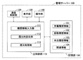
- the management server 100 includes a main control unit 110 including a microcomputer as a main unit, a communication control unit 120 for communicating with the outside via the communication line 50, a display unit 130, The operation unit 140 and a storage unit 150 that stores various types of information are provided.
- a main control unit 110 including a microcomputer as a main unit, a communication control unit 120 for communicating with the outside via the communication line 50, a display unit 130, The operation unit 140 and a storage unit 150 that stores various types of information are provided.
- the main control unit 110 includes a history information input unit 111, a return fee setting unit 112, and a return processing unit 113 when paying attention to its function.
- the history information input unit 111 inputs the charging history information and movement history information transmitted from the in-vehicle terminal 300 and the store visit history information transmitted from the office terminal 200 via the communication control unit 120, and the history information thereof. Is stored in the storage unit 150.
- the return fee setting unit 112 reads the charge history information, the movement history information, the store visit history information, and the relationship information stored in the storage unit 150, calculates the return fee for each vehicle ID based on the information, and returns Set the person who pays the fee.
- the reduction processing unit 113 transmits a payment instruction for a reduction fee.
- the storage unit 150 includes a charging history information storage area 151 in which charging history information is stored, a movement history information storage area 152 in which movement history information is stored, a store visit history information storage area 153 in which store visit history information is stored, A relation information storage area 154 in which relation information for associating various types of information is stored.
- relation information relating the vehicle ID and the vehicle user relation information relating the vehicle user and the customer ID, relation information relating the arrival point of the vehicle and the establishment ID
- It stores relationship information relating the payee's account number and the vehicle user (return target), relationship information relating the establishment ID and the payer of the return fee, and the like.
- Such relationship information correlates the vehicle user, vehicle ID, customer ID, and account number that are to be returned.
- the establishment ID, the arrival point, and the person who bears the return fee are associated with each other.
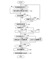
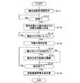
- FIG. 6 shows a movement history information generation / transmission routine executed by the main control unit 310 (mainly the movement history information generation / output unit 312) of the in-vehicle terminal 300.
- the movement history information generation / transmission routine is started when a start switch for starting the vehicle 30 is turned on.
- navigation control by the navigation control unit 311 is also started.
- the main control unit 310 determines whether or not a destination setting operation has been performed in step S11.
- the main control unit 310 reads the navigation control information and determines whether or not the destination setting of the vehicle 30 has been performed.
- the destination setting operation is performed, in step S12, the vehicle accumulated travel distance at that time is stored with the vehicle position at the time of setting as the vehicle departure point. For example, a value indicated by an odometer (not shown) is read and stored.
- step S12 If the destination setting operation is not performed (S11: No), the process of step S12 is skipped. Subsequently, in step S13, the main control unit 310 reads the navigation control information and determines whether or not the destination has been reached. If the destination is not set and if the destination has not arrived at the destination, main controller 310 determines “No” and advances the process to step S14.
- the main control unit determines whether or not an arrival button (not shown) is turned on in step S14.
- This arrival button is displayed as a button icon on the navigation screen of the display unit 320, and outputs an on signal (arrival signal) to the main control unit 310 by a touch operation of the vehicle occupant.
- the arrival button indicates that the vehicle 30 has arrived at the destination without waiting for the determination of arrival at the destination by the navigation control by touch operation when it is determined that the vehicle occupant has arrived at the destination.
- step S11 If the arrival button is not pressed, the main control unit 310 returns the process to step S11. In this way, the determination process of presence / absence of destination setting operation, presence / absence of destination arrival, presence / absence of arrival button operation is repeated. In step S11, once the destination setting operation is detected, the determination is “No” unless the destination setting operation is performed again. Therefore, the process in step S12 is performed only when the destination setting operation is performed.
- step S15 The arrival time that is the time is stored.
- step S16 the main control unit 310 determines whether or not the office 20 (store) can be specified based on the arrival point.
- the main control unit 310 refers to the vehicle position detected by the vehicle position detection unit 335.
- the occupant is only detected by the vehicle position detected by the vehicle position detection unit 335. Since it is difficult to specify the visited office 20, it is determined as “No”. If the destination setting performed by the occupant is set by specifying the office 20, the determination may be “Yes”.
- step S16 If it is determined as “Yes” in step S16, the store visit flag Fshop is set to “1” in step S17, and it is determined that the vehicle user has visited the office 20. On the other hand, if “No” is determined in step S16, the store visit flag Fshop is set to “2” in step S18 to temporarily determine that the vehicle user has visited the office.
- the store visit confirmation flag Fshop indicates that the vehicle user has not visited the business office 20 by “0”, indicates that the vehicle user has visited the business office 20 by “1”, and indicates that the vehicle user has been visited by “2”. This indicates that there is a possibility of visiting the office 20.
- step S19 the main control unit 310 determines whether or not the navigation destination has been set before the vehicle arrives at the arrival point. If the destination has been set, the travel distance from the vehicle departure point is calculated in step S20. As described above, when the destination is set, in step S12, the vehicle integrated travel distance at that time is stored. Therefore, in this step S20, the travel distance from the departure point to the arrival point is calculated by subtracting the cumulative vehicle travel distance stored in step S12 from the current cumulative travel distance represented by the odometer.
- step S12 instead of the process of storing the vehicle accumulated travel distance, the accumulation of the vehicle travel distance may be started from the destination setting time. Also by this, the travel distance from the departure point to the arrival point (current position) can be detected. Further, for example, in step S12, the vehicle position at the time of destination setting is detected and stored by the vehicle position detection unit 335, and in step S20, the travel distance on the map from this vehicle position to the arrival point is calculated. You may do it. In this case, if the shortest distance on the map from the vehicle position to the arrival point at the time of setting the destination is set as the travel distance, the travel distance traveled by the vehicle user for other purposes can be excluded.
- the vehicle user's home is regarded as the departure point, and the arrival point (current position) from the home. Calculate the mileage up to. In this case, the travel distance may be calculated using the shortest route on the map used for navigation control.
- the home position information used in navigation control (stored in the storage unit 340) may be used.
- the home position includes the position of a nearby parking lot where the vehicle user parks when returning home.
- the departure point is set to the home position set in advance in the navigation control unit 311.
- the departure point can be arbitrarily set.
- a departure button (not shown) may be displayed on the navigation screen of the display unit 320, and the vehicle position where the departure button is turned on by the vehicle occupant may be set as the departure point.
- the vehicle position when the departure button is pressed is stored in the storage unit 340, or the vehicle accumulated travel distance at that time is stored in the storage unit 340, or the accumulation of the vehicle travel distance is started from that time By doing so, the travel distance from the departure point to the arrival point can be detected.
- the vehicle position information when the start switch (not shown) for starting the vehicle is turned on or the vehicle position when the vehicle is turned off is sampled and accumulated over a long period of time, and the start switch is turned on or off from the accumulated information.
- the vehicle position with the highest frequency of turning off may be set as the starting position. This vehicle position can be estimated to be the vehicle user's home position.
- the main control unit 310 After calculating the travel distance in step S20 or step S21, the main control unit 310 subsequently determines whether or not the vehicle 30 has moved from the arrival point in step S22. That is, it is determined whether or not the vehicle user has gone away from the office 20 after performing business at the office 20 (shopping at a store). In this case, the main control unit 310 reads the vehicle position information detected by the vehicle position detection unit 335, and determines whether or not the vehicle position is more than a predetermined distance from the arrival point. The main control unit 310 repeats such determination until the vehicle 30 moves from the arrival point. And if it determines with the vehicle 30 having moved from the arrival point (S22: Yes), the residence time in the establishment 20 of a vehicle user will be calculated in step S23. In this case, main controller 310 calculates the elapsed time from the arrival time stored in step S15 to the current time, and sets the elapsed time as the stay time.
- step S24 the main control unit 310 generates movement history information, and transmits the generated movement history information to the management server 100 via the wireless communication control unit 330.
- the main control unit 310 reads the latest power consumption information calculated by the charging ECU 360 and also reads the vehicle ID that identifies the vehicle stored in the storage unit 340. Then, a set of travel history information in which the power consumption information, arrival point information, arrival date information, travel distance information, stay time information, and store visit flag information are related to the vehicle ID is generated, and the travel history information is managed by the management server. To 100.
- step S24 When the main control unit 310 transmits the movement history information in step S24, the movement history information generation / transmission routine is terminated.
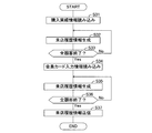
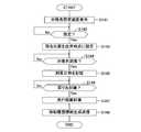
- FIG. 7 shows a store visit history information generation / transmission routine executed by the office terminal 200.
- the store visit determination flag Fshop is set to “2” in step S18 of the movement history information generation / transmission routine. Therefore, in this store visit history information generation / transmission routine, the vehicle user's store visit record is grasped, and information for determining the vehicle user's store visit is generated and transmitted.
- the store visit history information generation / transmission routine is executed, for example, when the business day of the office 20 ends.
- step S31 When the store visit history information generation / transmission routine is activated, the business establishment terminal 200 reads purchase record information for one day in step S31. Subsequently, in step S32, a set of store visit history information is generated by associating the customer ID for identifying the purchaser with the store visit date / time information, purchase price information, and the store ID for identifying the store. In this case, the purchase date / time information settled by the input device 280 is used as the store visit date / time information. Subsequently, in step S33, the business establishment terminal 200 determines whether or not store visit history information has been generated for all customer IDs. If generation of store visit history information for all customer IDs has not been completed, The process returns to step S32, and the above-described process is repeated.
- the business establishment terminal 200 reads the membership card input information for one day in step S34. Subsequently, in step S35, for the customer ID for which the store visit history information has not been generated in the previous step S32, the store visit history relating the store visit date / time information, the purchase price information, and the establishment ID for identifying the establishment to the customer ID. Generate information. In this case, the date and time when the membership card is read by the card reader 270 is used as the store visit date and time information. The purchase price information is information representing zero. Subsequently, in step S36, the business establishment terminal 200 determines whether or not store visit history information has been generated for all customer IDs. If generation of store visit history information for all customer IDs has not been completed, The process returns to step S35, and the above-described process is repeated.
- step S37 the business establishment terminal 200 transmits the store visit history information of all customer IDs to the management server 100 and ends the store visit history information generation / transmission routine.
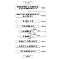
- FIG. 8 shows a store visit confirmation processing routine executed by the main control unit 110 of the management server 100.
- the main control unit 110 stores the charging history information in the charging history information storage area 151 of the storage unit 150, and every time movement history information is transmitted from the in-vehicle terminal 300.
- the movement history information is stored in the movement history information storage area 152 of the storage unit 150, and the store visit history information is stored in the store visit history information storage area 153 of the storage unit 150 each time the store visit history information is transmitted from the business office terminal 200.
- the main control unit 110 of the management server 100 reads the movement history information and the store visit history information stored in the storage unit 150 in step S51. Subsequently, in step S52, one piece of movement history information in which the store visit determination flag Fshop is set to “2” is extracted from the movement history information. Subsequently, in step S53, the extracted movement history information is collated with store visit history information.
- the relation information storage area 154 of the storage unit 150 stores relation information for associating the vehicle ID with the customer ID at the office. The customer ID is identified from the vehicle ID with reference to the relation information. Then, the visit history information of the customer ID is extracted, and the movement history information is compared with all the extracted visit history information. In this case, the arrival date information in the movement history information and the arrival date information in the visit history information are collated, and the arrival point information in the movement history information and the establishment ID are collated.
- step S54 the management server 100 determines the vehicle user's store visit performance based on this collation. For example, if the arrival point of the vehicle 30 is close to the location of the office 20 and the difference between the arrival date and time and the visit date is within a predetermined time, a determination condition for determining that there is a store visit result is set. The presence / absence of store visits is determined according to the conditions. If the main control unit 110 determines that there is a store visit record, the store control flag Fshop in the movement history information is rewritten from “2” to “1” in step S55. On the other hand, when it is determined that there is no store visit record, the store visit flag Fshop in the movement history information is rewritten from “2” to “0” in step S56.
- step S57 the main control unit 110 determines whether or not the matching between the movement history information and the visit history information is completed for all vehicle IDs. The process returns to step S52, and the above-described process is repeated.
- the store visit confirmation flag Fshop in the travel history information stored in the travel history information storage area 152 of the storage unit 150 is rewritten to “1” or “0” according to the store visit record.
- FIG. 9 shows a charge charge reduction processing routine executed by the main control unit 110 of the management server.
- the store visit determination process routine and the charge charge return process routine are executed in that cycle (for example, once a month).
- the charge charge reduction processing routine is executed after the store visit determination processing routine is executed.
- the main control unit 110 of the management server 100 reads the movement history information, the store visit history information, and the charging history information stored in the storage unit 150 in step S71. Subsequently, in step S72, one of the movement history information in which the store visit flag Fshop is set to “1” from the movement history information, and the charging history information corresponding to the vehicle ID included in the movement example history information. Are extracted for a predetermined period.
- step S73 the main control unit 110 determines whether or not the vehicle 30 is a charge charge reduction target based on the extracted charging history information.
- the condition for charge charge reduction can be set arbitrarily.
- the vehicle 30 which becomes more than is set as the charge reduction object.
- the vehicle 30 in which the number of times of charging green power is equal to or more than a preset number m (1 ⁇ m ⁇ n) in the last n times of charging is set as a charge reduction target.
- the vehicle 30 in which charging that has not been applied for the charging service is a predetermined number of times m ( ⁇ 1) or more is set as a charge reduction target. .
- a vehicle in which the proportion of the energy charged by the green power among the energy charged in the battery 350 or the proportion of the energy not applied with the charging service is equal to or greater than a predetermined value ⁇ (> 0). 30 may be a charge reduction target.
- the return target may be set based on the charging location.
- the vehicle 30 in which the ratio of home charging in the most recent n times of charging or the charging in the latest predetermined period is equal to or greater than a predetermined value ⁇ (> 0) may be the charge charge reduction target.
- the main control unit 110 calculates a store visit return charge A in the subsequent step S74.
- the store visit coefficient K1 is a value arbitrarily set for each store.
- the store visit coefficient K1 may be a value that increases as the number of visits increases, and conversely, a value that decreases as the number of visits increases. Or it may be a fixed value.
- the number of store visit history information (data count) for the vehicle ID may be set as the store visit count.
- the unit price P may be a unit price (average value or arbitrary one if there are a plurality of units) represented by the unit price information included in the charging history, or set by the office 20 in advance.
- the unit price set by the management center 10 may be used. Further, the latest unit price set by the power supply company 40 may be used.
- main controller 110 calculates stay return fee B in step S75.
- the stay return fee B is calculated by the following equation using, for example, the travel distance D, the electricity cost R, the power rate unit price P, and the stay coefficient K2.
- B (D / R) ⁇ P ⁇ K2
- the stay coefficient K2 is a value arbitrarily set for each store.
- the stay coefficient K2 may be a value that increases as the stay time increases, or conversely, a value that decreases as the stay time increases. Or it may be a fixed value.
- the stay coefficient K2 corresponding to the stay time is set, the stay time represented by the stay time information included in the movement history information may be used.
- the stay coefficient K2 that increases as the stay time increases may be set.
- the stay coefficient decreases as the stay time increases. What is necessary is just to set K2.
- the main control unit 110 calculates a purchase return fee C in step S76.
- the purchase return fee C is calculated by the following equation using, for example, the travel distance D, the power cost R, the power rate unit price P, and the purchase coefficient K3.
- C (D / R) ⁇ P ⁇ K3
- the purchase coefficient K3 is a value arbitrarily set for each store.
- the purchase coefficient K3 may be a value that increases as the purchase amount increases, or may be a fixed value.
- the purchase coefficient K3 corresponding to the purchase amount is set, the purchase amount represented by the purchase amount information included in the store visit history information may be used.
- step S77 the main control unit 110 selects the highest value among the store return charge A, the stay return charge B, and the purchase return charge C, and the selected charge is set for one visit. Set to the reduction fee X for battery charging.
- step S78 the main control unit 110 sets one set of information indicating the vehicle ID included in the movement history information, the establishment ID determined from the arrival point or the visit history information, and the calculated return fee X. Reducing fee information is generated.
- step S79 the main control unit 110 determines whether or not the return fee information has been generated for all the travel history information of the vehicle ID, and the generation processing of the return fee information regarding the other travel history information is performed. If it remains, the process from step S72 is repeated for the next movement history information. Thus, when the return fee information is generated for all the movement history information related to one vehicle ID (S79: Yes), the main control unit 110 has completed the generation of the return fee information for all the vehicle IDs in step S80. Judge whether or not. When the generation process of the return fee information regarding the other vehicle ID remains, the process from step S72 is repeated for the movement history information of the next vehicle ID. If it is determined in step S73 that the vehicle 30 is not to be returned, the process proceeds to step S80.
- the main control unit 110 After generating the reduction fee information for all the vehicle IDs, the main control unit 110 calculates the reduction fee for each vehicle ID in the subsequent step S81, that is, calculates the total value ( ⁇ X) of the reduction fee X, and continues to step S82. , The amount of burden is calculated for each establishment ID. Subsequently, in step S83, the main control unit 110 outputs a command for performing a reduction process, and ends the charge charge reduction process routine.
- the management server 100 includes relationship information (database) that associates the vehicle ID, the vehicle user, and the account number that pays the return fee, and relationship information (database) that associates the establishment ID and the bearer of the return fee. It is stored in the storage unit 150. Therefore, in step S83, the main control unit 110 outputs a remittance remittance processing command to the remittance department terminal (not shown) of the management center 10 to the account of the vehicle user specified by the vehicle ID, for example. A billing charge request command is output to the bearer identified by the place ID.
- the return charge may be reduced from the charge amount of the power usage charge that the power supply company 40 charges monthly.
- the management server 100 transmits information indicating the return target person and the return fee to the power establishment terminal 400, and also pays the establishment terminal 200 (if it is a burden person) to each burden. Send information that represents a fee.
- the amount obtained by subtracting the return fee from the power usage fee of the return target person is set as the amount charged to the return target person.
- the office 20 pays a burden fee to the power supply company 40.
- information indicating the person to be returned, return fee, account number, bearer, burden fee, etc. may be transmitted to an external organization such as a financial institution, and the return processing may be performed in a lump sum at the financial institution.
- the return fee is not limited to the amount, and may be a point of exchange for goods or services.
- restoration object may be specified based on charge log
- the vehicle charging charge reduction system of the present embodiment described above has the following effects.
- the vehicle user can receive a reduction of the charge even without charging at the office 20 (store), the vehicle user can travel and move while restraining his / her own burden. Moreover, in the business establishment 20, the guidance capability which invites a vehicle user to the business establishment 20 improves. 2. In the office 20, the malfunction that the parking lot is occupied with the vehicle for charge is suppressed. This increases customer turnover and improves sales. 3. Since the charging waiting time is shortened, convenience for the vehicle user is enhanced. It is particularly suitable for a vehicle user who needs battery charging immediately. In addition, the number of chargers 220 can be reduced.
- the establishment 20 can be specified based on the movement history information (arrival position information) of the vehicle, it is possible to easily set the vehicle user who receives the charge charge and the person who bears the return charge. 5. Even if the location cannot be identified from the arrival position of the vehicle, the vehicle user's store visit history information is used to authenticate the vehicle user's store visit, so charging is possible even at a private store instead of a large store such as a shopping center. You can join the fee reduction system.
- a desired return fee can be set for the burdener. For example, if the staying time at the establishment is preferable for the burdener, the reduction fee is increased as the staying time is longer. Conversely, if the staying time is preferable as the staying time is shorter, the return is reduced as the staying time is shorter. The fee can also be increased.
- the charging history information is referred to determine whether or not the charge is to be reduced, so that it is possible to prevent problems such as reducing charging charges more than necessary, and appropriate charging charges. Can be reduced.
- the charge history information includes information indicating the charge form, the charge form can be reflected in the calculation of the return amount or the return object. For example, only charging of green power can be targeted for reduction of the charge. In this case, the use of green power can be promoted.
- the information indicating the charging mode includes information regarding the application of the discount service, it is possible to exclude the charge that has received the discount service from the return target. As a result, a more appropriate charge reduction can be performed.
- the management server 100 corresponds to the vehicle energy replenishment charge returning device of the present invention.
- the in-vehicle terminal 300 corresponds to a movement history information providing unit of the present invention that provides movement history information to the vehicle energy supply fee return device.
- the in-vehicle terminal 300 and the charging ECU 360 correspond to the energy supply history information providing means of the present invention that provides energy supply history information to the vehicle energy supply fee reduction device.
- the vehicle charge charge reduction device and the vehicle charge charge reduction system as the second embodiment will be described.
- the second embodiment a configuration for setting a person who pays a return fee according to the purpose of travel of the vehicle user is added, and the other configuration is the above-described embodiment (referred to as the first embodiment). Is the same.
- parts different from the first embodiment will be described.
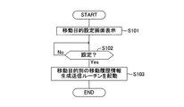
- FIG. 10 is a flowchart showing a movement purpose setting routine executed by the main control unit 310 (mainly the movement history information generation / output unit 312) of the vehicle terminal 300.
- the movement purpose setting routine is started when a start switch for starting the vehicle 30 is turned on.
- the main control unit 310 displays a movement purpose setting screen on the display unit 320 in step S101. On this screen, selection items (selection button icons) “shopping”, “travel”, “visit”, “commuting”, and “business trip” are displayed as the purpose of moving the vehicle 30. Subsequently, the main control unit 310 waits until the movement purpose is selected on the movement purpose setting screen by the occupant of the vehicle 30 in step S102, and when the movement purpose is selected, it is stored for each movement purpose in step S103. The movement history information generation / transmission routine is started to end the movement purpose setting routine.
- the movement purpose set as an initial value in advance is automatically selected.
- the user who uses the vehicle 30 for commuting sets the purpose of movement to “commuting” by the initial setting. Thereby, “commuting” is automatically set without performing a selection operation.
- a movement purpose setting button (button icon) may be displayed on the display unit 320, and the processing from step S101 may be started when the movement purpose setting button is turned on. In this case, when the movement purpose setting button is not turned on, a movement purpose set in advance as an initial value may be automatically selected.
- the main control unit 310 executes a movement history information generation / transmission routine similar to that of the first embodiment.
- a movement purpose ID that is information indicating the movement purpose is added to the movement history information.
- the movement purpose ID specifies that the movement purpose is “shopping”.
- the main control unit 310 executes a travel movement history information generation / transmission routine shown in FIG. 11 when the selected travel purpose is “travel”.
- the main control unit 310 When the travel movement history information generation / transmission routine is activated, the main control unit 310 first displays a sightseeing spot setting screen on the display unit 320 in step S111. On the sightseeing spot setting screen, a sightseeing spot may be selected on a map, a sightseeing spot may be selected from a sightseeing spot list, or characters may be input. Subsequently, the main control unit 310 waits until a sightseeing spot is selected in step S112, and when a sightseeing spot is selected, the vehicle position detection unit 335 detects in step S103, as shown in FIG. The travel distance from the departure point P1 to the sightseeing spot area S is calculated with the current vehicle position as the departure point P1. This distance is referred to as arrival travel distance D1. Note that the arrival travel distance D1 may be calculated with the departure point P1 as the home of the vehicle user. As the arrival travel distance D1, a distance on a map used for navigation control may be used.
- the main control unit 310 determines whether or not the vehicle 30 has entered the tourist area S based on the vehicle position detected by the vehicle position detection unit 335 in step S114. While the vehicle 30 is heading for a sightseeing spot, “No” is determined. Information representing this sightseeing spot area S is included in the map data in the storage unit 340 in advance.
- step S116 the main control unit 310 determines whether or not the vehicle is traveling in the tourist area S. If the vehicle is traveling in the tourist area S, the main controller 310 determines in step S117 that the vehicle Accumulate mileage. This travel distance is referred to as a tourism travel distance D2 (see FIG. 12). On the other hand, when it is determined that the vehicle 30 is not traveling in the sightseeing spot area S, the process of step S117 is skipped. Thereby, only when the vehicle 30 is traveling in the sightseeing area S, the travel distance D2 for sightseeing is sequentially accumulated.
- the main control unit 310 determines the end of sightseeing in step S118.
- the main control unit 310 repeats the processes of steps S116 to S118 until it is determined that the sightseeing has ended. Thereby, the travel distance D2 traveled by the vehicle user in the tourist area S is calculated in real time.
- the main control unit 310 determines that the sightseeing has ended, and in step S119, the movement history information is displayed.
- the generated travel history information is transmitted to the management server 100 via the wireless communication control unit 330, and the travel travel history information generation / transmission routine is terminated.
- the main control unit 310 reads the latest power consumption information calculated by the charging ECU 360 and also reads the vehicle ID for identifying the vehicle stored in the storage unit 340.
- the vehicle ID includes a travel purpose ID that is information for specifying a travel purpose (travel), a tourist destination ID (arrival point information) that is information for specifying a tourist destination, arrival date information, arrival travel distance D1 and travel travel.
- travel purpose ID information for specifying a travel purpose (travel)
- a tourist destination ID arrival point information
- arrival date information arrival travel distance D1 and travel travel travel.
- a set of travel history information relating the travel distance information representing the travel distance D2 and the power consumption information is generated, and the travel history information is transmitted to the management server 100.
- the travel movement history information generation / transmission routine is performed at that time by turning on the cancel button (button icon) displayed on the display unit 320. Ends.
- “visit” is a case where the vehicle user visits by invitation from an inviter. Therefore, as will be described later, the invitee becomes a person who bears the return fee. For example, “visit” is selected in the case of a party invitation, a wedding invitation, or the like.
- the main control unit 310 When the visit movement history information generation / transmission routine is activated, the main control unit 310 first displays an inviter setting screen on the display unit 320 in step S121. On the inviter setting screen, visited places are displayed on a map or in a list, and the visited place can be selected from this display screen. In this case, it is not necessary when the inviter can be identified from the visited place, but in many cases, the invited party cannot be identified only by the visited place. For example, since a plurality of organizations often use a wedding hall at the same time, an invitee cannot be specified even if only the wedding hall is specified.
- the main control unit 310 establishes communication connection with the visited terminal (office terminal 200) via the communication line 50, and invitees on the day (inviting person) And the list of invitees is not displayed on the display unit. For example, when the visit destination is a wedding hall, a list of all invitees who use the wedding hall on that day is displayed on the display unit 320.
- the main control unit 310 waits until an inviter is set by the vehicle occupant in step S122.
- the inviter is set, in step S123, the main control unit 310 sets an inviter ID that is information for identifying the inviter.
- This inviter ID is given to the inviter list information acquired from the visited terminal (office terminal 200).
- the main controller 310 sets the current vehicle position detected by the vehicle position detector 335 as a departure point. In this case, the main control unit 310 stores the current position (departure point) or stores the vehicle travel integrated distance. The departure point may be set at the vehicle user's home.
- step S125 the main control unit 310 determines whether or not the vehicle 30 has arrived at the visited location based on the vehicle position detected by the vehicle position detection unit 335. While the vehicle 30 has not arrived at the destination, it is determined as “No”.
- the main control unit 310 calculates the travel distance of the vehicle 30 from the departure point to the visited location in step S126.
- the distance on the map used for navigation control may be calculated as the travel distance, or the increase in the vehicle travel integrated distance indicated by the odometer may be calculated as the calculated travel distance.
- the accumulation of the travel distance of the vehicle 30 may be started from step S124, and the travel distance until the vehicle 30 arrives at the visit destination may be obtained.
- step S127 the main control unit 310 generates movement history information, transmits the generated movement history information to the management server 100 via the wireless communication control unit 330, and executes a visit movement history information generation / transmission routine. finish.
- the main control unit 310 reads the latest power consumption information calculated by the charging ECU 360 and also reads the vehicle ID for identifying the vehicle stored in the storage unit 340.
- the vehicle ID includes a movement purpose ID that is information for specifying a movement purpose (invitation), information indicating a place to visit (arrival point information), an inviter ID, arrival date and time information (may be current time), travel distance information, A set of movement history information associated with the power consumption information is generated, and the movement history information is transmitted to the management server 100.
- the cancel button displayed on the display unit 320 is turned on, and the visit movement history information generation / transmission routine is performed at that time. Ends.
- the main control unit executes a commuting movement history information generation / transmission routine shown in FIG.
- the main control unit 310 determines whether or not the vehicle 30 has arrived at the commuting destination based on the vehicle position detected by the vehicle position detection unit 335.
- the commuting location information is stored in advance in the storage unit 340 of the in-vehicle terminal 300.
- the main control unit 310 waits until the vehicle 30 arrives at the commuting destination.
- the attendance confirmation flag Fwork is set from “0” to “1” in step S132.
- the attendance determination flag Fwork indicates that the employee has worked by “1”, and indicates that the employee has not attended by “0”.
- the initial value when the commuting movement history information generation / transmission routine is started is set to “0”.
- step S133 the main control unit 310 generates movement history information, transmits the generated movement history information to the management server 100 via the wireless communication control unit 330, and executes a commuting movement history information generation / transmission routine. finish.
- the main control unit 310 reads the latest power consumption information calculated by the charging ECU 360 and also reads the vehicle ID for identifying the vehicle stored in the storage unit 340.
- the vehicle ID is related to a movement purpose ID, which is information for specifying a movement purpose (commuting), information representing the commuting destination (arrival point information), arrival date information (may be the current time), travel distance information, and power consumption information.
- a set of attached movement history information is generated, and the movement history information is transmitted to the management server 100.
- the cancel button (button icon) displayed on the display unit 320 is turned on, and the commuting movement history information generation / transmission routine ends at that time. In this case, the movement history information is not transmitted to the management server 100.
- main control section 310 executes a business trip movement history information generation / transmission routine shown in FIG.
- the main control unit 310 displays a business trip destination setting screen on the display unit 320 in step S141.
- business trip destinations are displayed on a map or in a list, and a business trip destination can be selected from this display screen.
- the business trip destination setting screen when a business trip destination is set, the screen is switched, the return destination is displayed on a map or in a list, and the return destination can be selected from the display screen.
- the return destination represents a place where the vehicle user returns after completing the business at the business trip destination.
- main controller 310 waits until the business trip destination and return destination are set by the vehicle occupant in step S142, and when these settings are made, in step S143, the current vehicle position is set as the departure point. To do.
- the main control unit 310 stores the vehicle travel integrated distance (odometer value) at this time in order to integrate the travel distance from this time.
- step S144 the main control unit 310 determines whether or not the vehicle 30 has arrived at the business trip destination based on the vehicle position detected by the vehicle position detection unit 335. While the vehicle 30 has not arrived at the business trip destination, “No” is determined.
- the main control unit 310 stores the arrival date and time at that time in step S145.
- step S146 the main control unit 310 determines whether the vehicle 30 has arrived at the return destination based on the vehicle position detected by the vehicle position detection unit 335. While the vehicle 30 has not arrived at the return destination, “No” is determined.
- the main control unit 310 calculates the travel distance of the vehicle 30 from the departure point to the return destination in step S147. In this case, the main control unit 310 calculates the travel distance for the business trip by reading the current travel distance of the vehicle from the odometer and subtracting the cumulative travel distance of the vehicle stored in step S145 from the accumulated travel distance of the vehicle.
- step S148 the main control unit 310 generates movement history information, transmits the generated movement history information to the management server 100 via the wireless communication control unit 330, and executes a business trip movement history information generation / transmission routine. finish.
- the main control unit 310 reads the latest power consumption information calculated by the charging ECU 360 and also reads the vehicle ID for identifying the vehicle stored in the storage unit 340. Then, a set of movements in which the vehicle ID is associated with a movement purpose ID, which is information for specifying a movement purpose (business trip), information indicating a business trip destination (arrival point information), arrival date / time information, travel distance information, and power consumption information. History information is generated, and the movement history information is transmitted to the management server 100.
- a movement purpose ID which is information for specifying a movement purpose (business trip), information indicating a business trip destination (arrival point information), arrival date / time information, travel distance information, and power consumption information. History information is generated, and the movement history information is transmitted to the management server 100.
- the cancel button (button icon) displayed on the display unit 320 is turned on, and the business trip movement history information generation / transmission routine ends at that time. In this case, the movement history information is not transmitted to the management server 100.
- FIG. 16 illustrates a charge charge reduction processing routine executed by the main control unit 110 of the management server 100.
- the charge charge return processing routine is executed in that cycle (for example, once a month).
- the main control unit 110 reads the movement history information, the visit history information, and the charging history information stored in the storage unit 150 in step S201. Subsequently, in step S202, one piece of movement history information is extracted, and a person who pays a return fee is set based on the movement purpose ID and arrival point information included in the movement history information.
- the purpose of movement is “shopping”, a burden person is set based on arrival point information indicating a store where the vehicle 30 has arrived, as in the first embodiment.
- the purpose of travel is “travel”
- the bearer is determined based on the sightseeing spot ID (arrival point information) representing the sightseeing spot.
- the tourism association in the tourist area is set as the bearer, and the store is not set as the bearer. Therefore, in a sightseeing spot, if the purpose of travel is “shopping”, the store corresponding to the arrival point becomes the bearer, and if the purpose of travel is “travel”, the tourism association becomes the bearer.
- a burden person is set based on arrival point information indicating a visited place or inviter ID. In this case, the inviter specified by the arrival point information or the inviter ID becomes the bearer.
- a burden person is set based on arrival point information indicating a commuting destination. For example, the company to which the vehicle user belongs is set as the bearer.
- a burden person is set based on arrival point information indicating a business trip destination. In this case, for example, a business trip destination may be a bearer, or a company to which a vehicle user belongs may be a bearer.
- related information that identifies the burden person from the movement purpose ID and the arrival point information is stored.
- information related to the inviter ID and the inviter is transmitted in advance from the office terminal 200 at the visited site (for example, wedding hall) to the management server 100, and the related information storage area 154 is stored. Is remembered.
- the main control unit 110 refers to the relationship information stored in the relationship information storage area 154 and sets a burden person.
- the main control unit 110 calculates a reduction fee X in step S203.
- the calculation formula of the return fee X is arbitrarily determined in advance by the bearer and is stored in the related information storage area 154 of the storage unit 150.
- the return target condition corresponding to the charging history is also set, and the main control unit 110, as described in the first embodiment, the charging history information corresponding to the vehicle ID included in the history information.
- the return fee X is calculated only for the vehicle 30 to be returned.
- the calculation method of the reduction fee X is demonstrated, this is an example and can be set freely.
- the main control unit 110 calculates the return fee X as described in the first embodiment, for example.
- the main control unit 110 calculates a return fee X based on the arrival travel distance D1 and the tourism travel distance D2 obtained from the travel distance information. For example, an upper limit distance D1max is set for the arrival travel distance D1.
- the main control unit 110 sets the travel distance D to (D1 + D2) if the arrival travel distance D1 is equal to or less than the upper limit distance D1max, and sets the travel distance D if the arrival travel distance D1 exceeds the upper limit distance D1max. Set to (D1max + D2). Then, using the electricity cost R and the electricity rate unit price P, the reduction fee X is calculated by the following equation.
- the main control unit 110 calculates a return fee X by a calculation method determined for each company to which the vehicle user belongs when the purpose of travel is “commuting”. In this case, since the distance between the vehicle user's home and the commuting destination does not vary, the distance is stored in advance in the storage unit 340 of the in-vehicle terminal 300.
- the in-vehicle terminal 300 reads travel distance information representing the travel distance D stored in the storage unit 340, and transmits the travel distance information including the travel distance information.
- information relating the vehicle ID and the travel distance D is transmitted in advance from the terminal of the company to which the vehicle user belongs (the establishment terminal 200) to the management server 100, and the relation information storage area 154 of the storage unit 150 is transmitted. You may make it memorize.
- the reduction target of the cost for battery charging may be set to be limited to green power.
- the main control unit 110 calculates the charging cost of green power in the most recent predetermined period (for example, the most recent one month) based on the power type information included in the charging history information (green power charging). Amount ⁇ green power unit price), and the amount of return X is calculated with the cost as the upper limit. According to this, the vehicle user can perform battery charging using expensive green power without worrying about self-pay. Therefore, the use of green power can be promoted.
- This return fee information is a set of information including the vehicle ID included in the movement history information, information for identifying the bearer, and information indicating the calculated return fee X.
- step S205 the main control unit 110 determines whether or not the return fee information has been generated for all the movement history information of the vehicle ID, and the generation processing of the return fee information regarding the other movement history information is performed. If it remains, the process from step S202 is repeated for the next movement history information.
- the main control unit 110 has completed the generation of the return fee information for all the vehicle IDs in step S206. Judge whether or not.
- the process from step S202 is repeated for the movement history information of the next vehicle ID.
- the main control unit 110 After generating the return fee information for all vehicle IDs, the main control unit 110 calculates a return fee ( ⁇ X) for each vehicle ID in the subsequent step S207, and calculates the burden amount for each burdener in the subsequent step S208. . Subsequently, in step S209, the main control unit 110 outputs a command for performing a reduction process, and ends the charge charge reduction process routine.
- the management server 100 stores related information necessary for the return processing in the storage unit 150, and refers to this related information, for example, the vehicle user specified by the vehicle ID.
- a remittance instruction for remittance of the return fee to the account is output to the terminal of the department in charge of remittance, and a request for charge of the burden fee is output to the bearer.
- the payment form of the reduction fee various things can be adopted as in the first embodiment.
- the setting of the payer can be made more appropriate. For example, even if the arrival point is a store, if the purpose of travel is “travel”, a tourism association can be set as the bearer.
- the travel purpose is “travel”
- the full amount of the battery charging cost for traveling the vehicle in the sightseeing area S is reduced, so that the vehicle user can go sightseeing without hesitation.
- activation is aimed at in a sightseeing spot, and a big merit is acquired in both a tourist association and a traveler.
- the upper limit is provided with respect to the return of the charge for traveling to the sightseeing spot area S, the return charge can be made appropriate, and the burden on the tourism association does not become excessive.
- the commuting allowance is appropriate. In other words, if a fixed amount is paid to employees as a commuting allowance every month, the amount paid may be different from the battery charging cost for actual vehicle commuting. Since the battery charge is reduced according to the commuting allowance, the commuting allowance is unlikely to occur. For example, when an employee takes a vacation, the commuting allowance on the vacation day is not paid, and conversely, when the employee goes to work on a holiday, the commuting allowance is paid accordingly. This provides significant benefits for both employees and the company.
- a burden person is set according to the business trip destination, so that the burden person can be appropriately set for the company.
- the bearer can be a company to which the vehicle user belongs, and when the business trip destination is an associated group company, the bearer can be set as the business trip destination.
- a reduction fee is appropriate.
- the vehicle charging charge reduction device and the vehicle charging charge reduction system according to the present embodiment have been described.
- the present invention is not limited to the above-described embodiment, and is not deviated from the object of the present invention. Various changes are possible.
- the charge charge required for charging the battery of the electric vehicle 30 is reduced.
- the fuel charge replenished to the gasoline vehicle may be reduced, and the fuel charge may be reduced.
- a configuration may be employed in which a share of fuel supplied to the battery vehicle is reduced.
- the in-vehicle terminal 300 has a wireless communication function, but the charging history information and the movement history information are transmitted to the management server 100 using a mobile terminal owned by the vehicle user. Also good.
- the in-vehicle terminal 300 and the mobile terminal may be connected by short-range wireless communication or wired communication, and the mobile terminal may read the charging history information and the movement history information stored in the in-vehicle terminal 300.
- the store visit history information and the movement history information of the vehicle 30 are collated to authenticate (determine) the movement of the vehicle user to the business place 20, but for example, the vehicle position In the system that can specify the office 20 only by using the store visit history information, it is not necessary.
- the present invention is applied to a charging fee reduction system in which both the establishment 20 provided with the charger 220 and the establishment 20 not provided with the charger 220 are mixed.
- the present invention may be applied to a charge charge reduction system provided with a charger 220.
- the charging fee reduction system may be provided independently of the power supply company 40.
- the return charge X at the time of visit is set using the store return charge A, the stay return charge B, and the purchase return charge C, but the calculation method of the return charge X can be arbitrarily set. It is. For example, if the vehicle travel distance is equal to or greater than a preset set distance, a preset fixed fee may be returned regardless of the travel distance.
- a map used for navigation control may be divided into a plurality of donut-shaped areas centered on the office 20, and a return fee may be set according to the area where the vehicle departure point exists.
- the charge related to the round trip to the office 20 may be returned. Moreover, you may make it calculate a reduction
- the travel history information includes travel distance information, but departure point information may be used instead of the travel distance information. This is because if the arrival point and the departure point are specified, the distance between the two points can be obtained as the travel distance.
- the charging history is stored in the charging ECU 360 of the vehicle 30.
- the charging history is stored in the power supply ECU 260 of the charger 220, and the charging history information is transmitted from the power supply ECU 260 to the management server 100. You may do it.
- the vehicle ID and the power consumption information may be transmitted from the charging ECU 360 to the power feeding ECU 260.
- the power supply ECU 260 transmits the charging date / time information, the charging amount information, the power rate unit price information, the power type information, the service application information, the charging location information, the power cost information, and the vehicle ID as charging history information via the communication line 50. be able to.
- charging history information may be transmitted from the household power home controller 80 (see FIG. 1) to the management server 100.
- the charging ECU 350 of the vehicle 30 and the power home controller 80 are connected by power line carrier communication (PLC), and the vehicle ID, power consumption information, charging amount information, and charging date / time information are transmitted from the charging ECU 350 to the power home controller 80.
- PLC power line carrier communication
- the power home controller 80 transmits charging history information obtained by adding power unit price information, power type information, service application information, and charging location information to the information to the management server 100.
- the power consumption information is included in the movement history information and transmitted from the in-vehicle terminal 300 to the management server 100.
- the power consumption information is not included in the movement history information and is transmitted alone with the vehicle ID. It may be.
- the structure which does not use electricity cost information may be sufficient.
- the movement purpose ID is included in the movement history information and transmitted from the in-vehicle terminal 300 to the management server 100.
- the movement purpose ID is not included in the movement history information and alone with the vehicle ID. You may make it transmit.
- one is selected from a plurality of movement purposes, but may be a configuration in which the movement purpose is fixed to one.
- it may be any of shopping-only, travel-only, commuting-only, business-only, and visit-only.
- the movement history information generation output unit 312 of the in-vehicle terminal device 300 in the second embodiment corresponds to the movement purpose information providing unit of the present invention.
Landscapes
- Business, Economics & Management (AREA)
- Engineering & Computer Science (AREA)
- Economics (AREA)
- Entrepreneurship & Innovation (AREA)
- Human Resources & Organizations (AREA)
- Marketing (AREA)
- Operations Research (AREA)
- Quality & Reliability (AREA)
- Strategic Management (AREA)
- Tourism & Hospitality (AREA)
- Physics & Mathematics (AREA)
- General Business, Economics & Management (AREA)
- General Physics & Mathematics (AREA)
- Theoretical Computer Science (AREA)
- Electric Propulsion And Braking For Vehicles (AREA)
Abstract
管理サーバー100は、車載端末300から移動履歴情報と充電履歴情報とを取得する。管理サーバー100は、移動履歴情報と充電履歴情報とに基づいて、車両30を事業所20まで走行させるためにかかるバッテリ充電料の一部あるいは全部を車両ユーザに還元させる。移動履歴情報には、車両30の到着位置情報、出発地点からの走行距離情報が含まれている。管理サーバー100は、到着地点情報から事業所20を特定し、その事業所20から負担者を設定する。また、走行距離情報に基づいて還元料を計算する。これにより、車両ユーザは、指定された場所でバッテリ充電を行わなくても、充電料の還元を受けることができる。
Description
本発明は、車両の走行用エネルギーの補給料を車両ユーザに還元する装置およびシステムに関する。
従来から、電気自動車やプラグイン・ハイブリッド車といった電動車両のバッテリを充電施設で充電した際に、その充電料金を割り引くようにした充電システムが提案されている。例えば、特許文献1に提案されている車両の充電システムは、充電施設で電動車両のバッテリを充電した際に、広告提供者から広告情報を車両のナビゲーション装置に送信して車載ディスプレイに広告を表示し、その広告と引き換えに、充電料金を割り引くようにしたシステムを構成している。
また、最近においては、充電インフラの整備の一環として、レストラン、コンビニエンスストア、ショッピングセンターなどの店舗や、娯楽施設に充電器を設けた充電システムも考えられている。電動車両の充電には長い時間がかかる。従って、こうした充電システムにおいては、充電時間を利用して買い物ができるというメリットがある。また、買い物をしたポイントで、充電料金を割引サービスをする充電システムも考えられている。
しかしながら、買い物に出かける場合、航続可能距離を確保するために、予め自宅のコンセントからバッテリを十分に充電しておく可能性が高い。そうした場合には、店舗等の出先での充電を行う必要が無く、車両のユーザは、充電料金の割引のメリットを受けられない。また、充電時間が通常の買い物時間より長くかかるため、店舗の駐車場が充電を行う車両で占有されてしまい、充電を必要としない車両のユーザにとって迷惑となる。また、店舗にとっても、客の入れ替わりが停滞してしまい、業績に悪影響を及ぼす。この結果、車両のユーザ側と店舗側との双方においてディメリットが生じる。
本発明の目的は、上記問題に対処するためになされたもので、車両を使用する側にとっても、また、車両を使って人を招こうとする側にとってもメリットが得られるようにすることを目的とする。
上記目的を達成するために、本発明の車両用エネルギー補給料還元装置の特徴は、車両の移動履歴を表す移動履歴情報を、当該車両のユーザを特定できる車両関連情報と対応付けて取得する移動履歴情報取得手段(111,152,S71)と、車両に走行用エネルギーを補給した履歴を表すエネルギー補給履歴情報を、前記車両関連情報と対応付けて取得するエネルギー補給履歴情報取得手段(111,151,S71)と、前記取得した移動履歴情報とエネルギー補給履歴情報とに基づいて、エネルギー補給に関する還元料および還元料を負担する負担者を設定する還元料設定手段(112,S73~S78)と、前記設定された還元料を前記車両のユーザに還元するための処理を行う処理手段(113,S83)とを備えたことにある。
本発明においては、移動履歴情報取得手段が、車両の移動履歴情報を、当該車両のユーザを特定できる車両関連情報と対応付けて取得する。例えば、移動履歴情報取得手段は、GPS等の車両位置検出装置により検出された車両移動位置を表す情報を取得する。また、エネルギー補給履歴情報取得手段は、車両に走行用エネルギーを補給した履歴情報であるエネルギー補給履歴情報を、車両関連情報と対応付けて取得する。この車両関連情報は、車両のユーザを特定できる情報であればよく、例えば、車両を特定する車両ID(登録番号など)でもよい。車両IDから、車両のユーザを特定することができるからである。
また、補給する車両用走行エネルギーとしては、電気エネルギー、つまり、車両の走行用バッテリを充電するための電力が好ましいが、エンジン駆動用のエネルギー、つまり、ガソリン等の燃料であってもよい。
還元料設定手段は、移動履歴情報とエネルギー補給履歴情報とに基づいて、エネルギー補給に関する還元料および還元料を負担する負担者を設定する。例えば、移動履歴情報から得られる車両の移動場所から、その移動場所に招いた者(例えば、店舗)を特定することができる。還元料設定手段は、例えば、その移動場所に招いた者を、エネルギー補給に関する還元料の負担者として設定する。
エネルギー補給料を還元するにあたっては、車両のユーザが車両のエネルギー補給を行ったという実績を確認しないと、必要以上にエネルギー補給料を還元してしまう可能性がある。そこで、還元料設定手段は、移動履歴情報だけでなくエネルギー補給履歴情報に基づいて還元料を設定する。還元料は、金額に限るものではなく、商品やサービスの引き替えポイント等であってもよい。また、還元料は、エネルギー補給に要した費用の全部に限らず一部であってもよい。
こうして、還元料と負担者が設定されると、処理手段は、設定された還元料を車両のユーザに還元するための処理を行う。例えば、還元指令を出力する。これにより、エネルギー補給料が車両のユーザに還元される。還元指令は、負担者に出力してもよいし、エネルギー補給事業者に出力してもよいし、それ以外の者、例えば、金融機関に出力してもよい。つまり、最終的に、車両のユーザにエネルギー補給料が還元されればよいのであって、還元されるまでの過程は任意に設定することができる。
従って、本発明によれば、車両のユーザは、エネルギー補給を指定場所において行わなくても、エネルギー補給料の還元を受けることができる。これにより、車両ユーザは、エネルギー補給に必要な自己負担を抑えて走行移動することができる。また、車両を使って人を招こうとする側にとっても、招きやすくなる。これらの結果、車両を使用する側にとっても、また、車両を使って人を招こうとする側にとっても大きなメリットが得られる。例えば、店舗、娯楽施設、観光地などに本発明を導入することで、集客能力が向上するとともに、来客側も自己負担が軽減される。
本発明の車両用エネルギー補給料還元装置の他の特徴は、前記移動履歴情報は、車両の到着地点を表す情報と、車両の出発地点を表す情報あるいは前記出発地点から前記到着地点までの走行距離を表す情報とを含んでいることにある。
本発明においては、車両の到着地点を表す情報を取得することにより、車両が到着地点にまで走行したという実績、および、車両を到着地点に招いた者(例えば、店舗)を把握することができる。また、出発地点を表す情報を取得することにより、あるいは、出発地点から到着地点までの走行距離を表す情報を取得することにより、到着地点までの走行距離を把握することができる。この結果、出発地点から到着地点までの走行距離に基づいて、還元料を設定することができる。これにより、還元料を車両ユーザの負担に応じた適切なものにすることができる。
本発明の車両用エネルギー補給料還元装置の他の特徴は、前記還元料設定手段は、還元料を負担する負担者と車両の到着地点とを関係付けた関係情報を記憶しており(154)、前記関係情報と前記移動履歴情報に基づいて、負担者を設定することにある。
本発明においては、負担者と車両の到着地点とが関係情報により関係付けられているため、車両の移動履歴情報における到着地点から、還元料を負担する負担者を簡単に設定することができる。
本発明の車両用エネルギー補給料還元装置の他の特徴は、前記移動履歴情報取得手段は、車両ユーザの自宅位置、あるいは、車両の目的地が設定された時の車両位置を、前記車両の出発地点とした情報を取得することにある。
本発明によれば、車両の出発地点を簡単に特定することができるため、車両の走行距離を容易に推定することができる。尚、車両ユーザの自宅位置とは、例えば、ナビゲーション装置で予め設定した自宅位置でもよいし、車両ユーザの自宅付近の駐車場であってもよいし、あるいは、車両の移動履歴から推定した自宅位置であってもよい。
本発明の車両用エネルギー補給料還元装置の他の特徴は、前記移動履歴情報は、前記車両が到着地点に到着してから離れるまでの滞在時間を表す滞在時間情報を含んでおり、前記還元料設定手段は、前記滞在時間情報に基づいて、前記還元料を変更することにある。
本発明においては、車両の到着地点における滞在時間を表す滞在時間情報を含めた移動履歴情報を取得し、滞在時間に基づいて還元料を変更するため、負担者にとって所望の還元料を設定することができる。例えば、到着地点が店舗である場合、その店舗にとって、滞在時間が長いほど好ましいのであれば、滞在時間が長くなるほど還元料を大きくし、逆に、滞在時間が短いほど好ましいのであれば、滞在時間が短くなるほど還元料を大きくするとよい。
本発明の車両用エネルギー補給料還元装置の他の特徴は、前記エネルギー補給履歴情報は、走行用エネルギーの補給形態を表す情報を含んでいることにある。
走行用エネルギーの補給形態は、例えば、通常の定価にて走行用エネルギーを補給する形態、無料も含めた割引サービスを受けて走行用エネルギーを補給する形態、あるいは、通常よりも高額の走行用エネルギー(例えば、グリーン電力)を補給する形態などが考えられる。本発明においては、こうした走行用エネルギーの補給形態を表す情報がエネルギー補給履歴情報に含まれている。従って、所望の形態の走行用エネルギーの補給に関して還元対象とすることができる。このため、エネルギー補給に関する還元を一層適切にすることができる。
本発明の車両用エネルギー補給料還元装置の他の特徴は、車両の補給エネルギー量と走行可能距離との関係を表すエネルギー効率情報を、前記車両関連情報と対応付けて取得する効率情報取得手段(111,151)を備え、前記還元料設定手段は、前記移動履歴情報と前記エネルギー補給履歴情報とに加えて前記取得したエネルギー効率情報に基づいて、前記エネルギー補給に関する還元料を設定する(S74~S76)ことにある。
本発明においては、効率情報取得手段が、車両の補給エネルギー量と走行可能距離との関係を表すエネルギー効率情報を取得する。このエネルギー効率とは、例えば、単位補給エネルギー量あたりに車両が走行できる距離を表す値、あるいは、車両が単位距離を走行するのに必要な補給エネルギー量を表す値であり、ガソリン車であれば燃費と呼ばれるものに相当する。このエネルギー効率は、車両によってそれぞれ異なる。還元料設定手段は、このエネルギー効率情報を加味して還元料を設定する。従って、本発明によれば、一層適切な還元料を設定することができる。
本発明の車両用エネルギー補給料還元装置の他の特徴は、車両を走行移動させるための目的を表す移動目的情報を、前記車両関連情報と対応付けて取得する移動目的情報取得手段(111,152,S201)を備え、前記還元料設定手段は、前記取得した移動目的情報に基づいて、前記還元料を負担する負担者を設定する(S202)ことにある。
車両の到着地点だけでは還元料の負担者を適正に設定できないケースも生じる。そこで本発明においては、移動目的情報取得手段が、車両を走行移動させるための目的を表す移動目的情報を車両関連情報と対応付けて取得する。そして、還元料設定手段が、移動履歴情報と移動目的情報に基づいて還元料を負担する負担者を設定する。従って、本発明によれば、還元料の負担者を更に適正に設定することができる。
本発明は、車両用エネルギー補給料還元装置だけでなく、車両用エネルギー補給料還元システムにも適用することができる。この車両用エネルギー補給料還元システムの特徴は、前記車両用エネルギー補給料還元装置(100)と、前記車両用エネルギー補給料還元装置に、前記移動履歴情報を前記車両関連情報と対応付けて提供する移動履歴情報提供手段(300,312,S24)と、前記車両用エネルギー補給料還元装置に、前記エネルギー補給履歴情報を前記車両関連情報と対応付けて提供するエネルギー補給履歴情報提供手段(300,372)とを備えたことにある。
本発明においては、車両用エネルギー補給料還元装置に対して、移動履歴情報提供手段が移動履歴情報を車両関連情報と対応付けて提供し、エネルギー補給履歴情報提供手段がエネルギー補給履歴情報を車両関連情報と対応付けて提供する。
また、本発明の車両用エネルギー補給料還元システムの他の特徴は、前記車両用エネルギー補給料還元装置(100)と、前記車両用エネルギー補給料還元装置に、前記移動履歴情報を前記車両関連情報と対応付けて提供する移動履歴情報提供手段(300,312,S24)と、前記車両用エネルギー補給料還元装置に、前記エネルギー補給履歴情報を前記車両関連情報と対応付けて提供するエネルギー補給履歴情報提供手段(300,372)と、前記車両用エネルギー補給料還元装置に、前記移動目的情報を前記車両関連情報と対応付けて提供する移動目的情報提供手段(300,312,S119,S127,S133,S148)とを備えたことにある。
本発明においては、車両用エネルギー補給料還元装置に対して、移動履歴情報提供手段が移動履歴情報を車両関連情報と対応付けて提供し、エネルギー補給履歴情報提供手段がエネルギー補給履歴情報を車両関連情報と対応付けて提供し、移動目的情報提供手段が移動目的情報を車両関連情報と対応付けて提供する。
尚、上記説明においては、発明の理解を助けるために、実施形態に対応する発明の構成に対して、実施形態で用いた符号を括弧書きで添えているが、発明の各構成要件は、前記符号によって規定される実施形態に限定されるものではない。
以下、本発明の一実施形態としての車両用充電料還元装置、および、車両用充電料還元システムについて説明する。図1は、実施形態に係る車両用充電料還元システムを表す概略図である。
車両用充電料還元システムは、車両ユーザが店舗等の目的地に行くまでの車両走行に必要な充電料金の全部または一部を、車両ユーザを招いたものが負担者となって、車両ユーザに還元するシステムである。還元料は、予め定めたルールにしたがって設定される。車両用充電料還元システムは、車両用充電料還元システムを統括する管理センター10に設けられる管理サーバー100と、車両用充電料還元システムに登録されている複数の事業所20に設けられる事業所端末200と、車両30に設けられる車載端末300と、電力供給会社40に設けられる電力事業所端末400とを備える。管理サーバー100は、本発明の車両用充電料還元装置に相当する。管理サーバー100、事業所端末200、車載端末300、電力事業所端末400は、インターネットなどの通信回線50によって相互に通信可能に接続される。通信回線50には無線基地局60が接続され、この無線基地局60を介して通信回線50と車載端末300とが接続される。
この実施形態においては、事業所20は、店舗を想定しているが、店舗に限るものではなく、車両ユーザを招こうとするものに適用することができる。また、この実施形態においては、車両30は、バッテリ350を備え、外部電源からバッテリ350に充電できるようにしたプラグイン電気車両である。例えば、バッテリ350の電力で走行用モータを駆動する電気自動車がその代表であるが、走行用モータと内燃機関とを備えたプラグイン式ハイブリッド自動車であってもよい。また、電動自転車、アシスト自転車、電動バイクなどの二輪車であってもよい。
複数の事業所20には、車両30のバッテリ350に電力を供給する充電器220(例えば、急速充電器)が設置されている。充電器220は、買い物中にバッテリ350を充電できるように駐車場に複数設けられている。尚、この事業所20は、充電ステーションのような車両30のバッテリ充電を主業務とするものではなく、充電設備のインフラ支援として充電器220を備えたものであるが、バッテリ充電を主業務とする充電事業所を含んでいても良い。また、事業所20としては、充電器220を備えていないものを含んでいても良い。
以下、事業所20を店舗とした例を説明するため、事業所20に訪れる者を客、事業所20を店舗と呼ぶことがある。
図2は、充電器220と車両30の概略構成を表す。最初に、充電器220について説明するが、この充電器220は、事業所20に設けられるものに限らず、充電ステーション等の充電事業所に設けられるものと同等である。充電器220は、電力供給会社40から電力供給網(例えば、スマートグリッド)を介して商用電力が供給される。充電器220は、充電用ケーブル221を備えており、充電用ケーブル221の先端に設けられたプラグ222を車両の受電コネクタ31に差し込むことにより、車両30のバッテリ350に電力供給する。
この充電器220は、給電の開始と終了を指示する操作部230と、給電状況や操作方法等の情報を利用者に知らせる表示部240と、料金を精算する料金精算部250と、ケーシング内に設けられ電力供給を制御する給電制御ユニット260(以下、給電ECU260と呼ぶ)とを備えている。給電ECU260は、マイクロコンピュータを主要部として備え、バッテリ350への電力供給を制御するとともに電力供給量を測定する機能と、充電用ケーブル221を介在させた電力線搬送通信(PLC:Power Line Communication)を行って車両30に充電情報を送信する機能を備えている。
電力線搬送通信により車両30に送信する充電情報には、充電の日時を表す情報、充電時における電力料金の単価を表す情報、充電量を表す情報、充電器を識別する情報、および、充電形態を表す情報が含まれている。ここで、充電形態を表す情報とは、通常の定価での充電、割引による充電、無料による充電といった充電サービスの適用に関する情報と、充電電力の種類(通常電力orグリーン電力)を表す情報である。
尚、グリーン電力とは、地球環境に対する負荷が相対的に低い方法により発電された電力を表す。地熱発電、風力発電、太陽光発電は、二酸化炭素の排出量がほとんどゼロであるため、火力発電と比較して地球環境に対する負荷が相対的に低い。このような自然エネルギーを利用して発電された電力がグリーン電力である。
給電ECU260は、事業所端末200に接続され、各種の充電情報を送信する。事業所端末200は、マイクロコンピュータを主要部として備え、給電ECU260から送信される充電情報を入力し、充電状況をモニタする。また、事業所端末200は、管理サーバー100と通信回線50を介して接続され、管理サーバー100とのあいだで充電料金の還元に関する情報の送受信を行う。
事業所20には、客が来店したことを認証するためのカード読み取り機270を備えている。このカード読み取り機270は、事業所端末200に接続されており、店舗会員カードから読み取った客を識別する顧客IDを読み取る。来店した客は、各自の店舗会員カードをカード読み取り機270に挿入する。これにより、事業所端末200は、来店した客を特定できるようになっている。また、事業所端末200には、クレジットカードや携帯端末により電子マネー決済するための入力装置280が接続されている。入力装置280は、マイクロコンピュータを主要部として備え、通常の電子マネー決済を行うための機能に加えて、来店者の当該事業所20での購入実績情報を事業所端末200に出力する機能を備えている。これにより、来店者がカード読み取り機270に店舗会員カードを挿入しなくても、購入実績情報により来店者を特定することができ、また、その購入金額を把握することができるようになっている。
事業所端末200は、来店した客を特定する情報である顧客IDと、各顧客IDごとに、その来店日時を表す日時情報と、購入金額を表す購入額情報とを、事業所IDとともに管理サーバー100に送信する。こうした情報を来店履歴情報と呼ぶ。来店履歴情報は、充電料金の還元を行うための情報として利用されるが、必ずしも必要とされるものではない。従って、充電料還元システムには、カード読み取り機270や入力装置280を備えていない事業所20も含まれていてもよい。
車両30は、図2に示すように、走行駆動系として、バッテリ350から出力される直流電力を三相交流電力に変換するインバータ351と、インバータ351から出力される三相交流電力により駆動されて車輪Wを回転させる走行用のモータ352と、運転者の運転操作に応じてインバータ351の出力を制御するモータ制御ユニット353(モータECU353と呼ぶ)とを備えている。
また、車両30は、バッテリ350を充電するための回路として、受電コネクタ31に供給される交流電力を直流電力に変換するAC/DC変換器354と、バッテリ350の充電を制御する充電制御ユニット360(以下、充電ECU360と呼ぶ)を備えている。
バッテリ350は、上述した充電器220から充電できるだけでなく、図1に示すように、家庭に設けられた電源コンセント70から充電できる。家庭の電源コンセント70から充電する場合には、充電用ケーブル71の一方のプラグ72を家庭の電源コンセント70に差し込み、他方のプラグ73を受電コネクタ31に差し込めばよい。
受電コネクタ31からAC/DC変換器354への電力供給ライン356には、充電スイッチ357が設けられる。この充電スイッチ357は、充電ECU360からの制御信号によりオン状態とオフ状態とに切り替え可能となっている。バッテリ350には、バッテリ350の充電状態を示す値であるSOC(State Of Charge)を検出するSOC検出部358が設けられる。SOC検出部358は、SOCを表す信号を充電ECU360に出力する。
充電ECU360は、図3に示すように、マイクロコンピュータを主要部として備えた主制御部370と、充電器220の給電ECU260と電力線搬送通信(PLC:Power Line Communication)を行うためのPLC通信制御部380と、各種のデータを記憶するための記憶部390とを備えている。PLC通信制御部380は、PLC用ライン381にて電力供給ライン356に接続され、PLC用ライン381、電力供給ライン356、充電用ケーブル221を介して給電ECU260と接続される。
主制御部370は、その機能に着目すると、充電制御部371と充電履歴情報生成部372とを備えている。各機能部371,372は、マイクロコンピュータの制御プログラムの実行により実現されるものである。充電制御部371は、SOC検出部358から出力されるSOCを入力し、SOCが第1基準値よりも低い場合は、充電スイッチ357をオン状態にしてAC/DC変換器354に電力を供給するとともに、AC/DC変換器354を作動させてバッテリ350を充電する。また、SOCが第2基準値(>第1基準値)以上である場合は、充電スイッチ357をオフ状態にするとともに、AC/DC変換器354を停止させてバッテリ350の充電を停止する。これにより、バッテリ350の蓄電量を適正範囲に維持することができる。
また、充電制御部371は、所定の周期で、単位充電量あたりの車両走行距離を表す電費を計算し、最新の電費情報を記憶部390に記憶する。電費は、ガソリン車における燃費に相当するものである。
PLC通信制御部380は、充電用ケーブル221を介して外部から充電情報を受信する。上述したように、充電器220は、給電ECU260を備えており、この給電ECU260から充電情報を出力する。PLC通信制御部380は、給電ECU260から出力される充電情報を充電用ケーブル221を介して入力し、この充電情報を充電履歴情報生成部372に出力する。
また、PLC通信制御部380は、家庭に設けられた電源コンセント70から充電する場合においては、充電用ケーブル71を介して電力情報を受信する。電力供給会社は、各家庭に電力供給するための電力供給網を使って、PLC通信により電力情報を送信している。この電力情報には、電力の種類(通常電力orグリーン電力)を表す情報、電力料金の単価を表す情報、サービスの適用に関する情報が含まれている。従って、充電用ケーブル71を介して家庭の電源コンセント70から充電した場合には、この電力情報がPLC通信制御部380に送信される。PLC通信制御部380は、この電力情報を充電履歴情報生成部372に出力する。
充電履歴情報生成部372は、PLC通信制御部380からこうした情報が出力される都度、それらの情報を1組の充電情報として記憶部390に記憶する。この場合、家庭の電源コンセント70から充電した場合には、充電量を表す情報を入手できていないため、充電履歴情報生成部372は、SOC検出部358から充電開始時と充電終了時とにおける充電状態の変化量を充電量とみなして充電量情報を生成する。あるいは、バッテリ350に流れる電流の積算値を測定して、充電料を計算するようにしてもよい。
また、充電履歴情報生成部372は、自宅充電と、外部充電(出先での充電器を使った充電)とを識別する充電場所情報も生成する。外部充電の場合には、充電情報のなかに充電器220を識別する情報が送信されるため、その情報の有無に基づいて、充電場所情報を生成することができる。尚、この充電場所情報は、充電形態に関する情報として利用することもできる。
このようにして、充電履歴情報生成部372は、PLC通信制御部380から情報が出力される都度、充電日時情報、充電量情報、電力料金単価情報、電力種類情報、サービス適用情報、充電場所情報を1組のデータとして関連付けた充電情報を生成し、生成した充電情報を記憶部390に記憶する。こうして、記憶部390には、バッテリ350が充電される度に充電情報が逐次記憶される。このように記憶部390に記憶された充電情報が充電履歴情報となる。尚、本明細書において、情報を生成するとは、データを作成することをいう。
充電ECU360は、車載端末300と接続されている。車載端末300は、ナビゲーション装置を兼用したものであり、図4に示すように、マイクロコンピュータを主要部として備えた主制御部310と、タッチパネル式ディスプレイで構成される表示部320および操作部325と、無線基地局60を介して外部と交信するための無線通信制御部330と、GPS衛星からの電波に基づいて自車両の現在位置座標を検出するGPSユニットおよび車両の進行方向を検出するジャイロセンサを備えた車両位置検出部335と、地図データ、施設データや、後述する移動履歴情報を生成するために必要な各種データ等を記憶する記憶部340とを備えている。
主制御部310は、その機能に着目すると、自車両を目的地に案内するナビゲーション制御部311と、移動履歴情報生成出力部312と、充電履歴情報出力部313とを備えている。充電履歴情報出力部313は、予め定められたタイミングで、充電ECU360の記憶部390に記憶されている充電履歴情報を読み込み、読み込んだ充電履歴情報に車両を識別する車両ID(例えば、車両の登録番号など)を付加して無線通信制御部330に出力する。この場合、充電履歴情報出力部313は、一度読み込んだ充電履歴情報を次回にも読み込まないように、記憶部390に記憶されている充電履歴情報に、読み込み済みであることを表す識別情報を付加する。充電履歴情報の出力タイミングは、任意に設定できる。例えば、バッテリ350の充電の終了が検出された都度、充電履歴情報を出力するようにしてもよいし、所定日数分の充電履歴情報をまとめて出力するようにしてもよい。
移動履歴情報生成出力部312は、車両位置検出部335により検出される車両位置およびナビゲーション制御部311の設定等に基づいて車両の移動履歴情報を生成し、この移動履歴情報に車両IDを付加して無線通信制御部330に出力する。以下、車両IDを関係付けた充電履歴情報を単に充電履歴情報と呼び、車両IDを関係付けた移動履歴情報を単に移動履歴情報と呼ぶ。
無線通信制御部330は、充電履歴情報出力部313から充電履歴情報を入力したとき管理サーバー100に対して充電履歴情報を送信し、移動履歴情報生成出力部312から移動履歴情を入力したとき管理サーバー100に対して移動履歴情報を送信する。
管理サーバー100は、図5に示すように、マイクロコンピュータを主要部として備えた主制御部110と、通信回線50を介して外部との交信を行うための通信制御部120と、表示部130と、操作部140と、各種の情報を記憶する記憶部150とを備えている。
主制御部110は、その機能に着目すると、履歴情報入力部111と、還元料設定部112と、還元処理部113とを備えている。履歴情報入力部111は、車載端末300から送信される充電履歴情報および移動履歴情報と、事業所端末200から送信される来店履歴情報とを通信制御部120を介して入力し、それらの履歴情報を記憶部150に書き込む。還元料設定部112は、記憶部150に記憶された充電履歴情報と移動履歴情報と来店履歴情報と関係情報とを読み出し、それらの情報に基づいて、車両ID毎の還元料を計算するとともに還元料の負担者を設定する。還元処理部113は、還元料の支払い指令を送信する。
記憶部150は、充電履歴情報が記憶される充電履歴情報記憶エリア151と、移動履歴情報が記憶される移動履歴情報記憶エリア152と、来店履歴情報が記憶される来店履歴情報記憶エリア153と、各種の情報を関係付けするための関係情報が記憶される関係情報記憶エリア154とを備えている。関係情報記憶エリア154には、車両IDと車両ユーザとを関係付ける関係情報、車両ユーザと顧客IDとを関係付ける関係情報、車両の到着地点と事業所IDとを関係付ける関係情報、還元料の支払先の口座番号と車両ユーザ(還元対象者)とを関係付ける関係情報、事業所IDと還元料の負担者とを関係付ける関係情報等を記憶している。こうした関係情報により、還元対象者となる車両ユーザ、車両ID、顧客ID、口座番号が相互に関係付けられる。また、事業所ID、到着地点、還元料の負担者が相互に関係付けられるようになっている。
次に、車載端末300の処理について説明する。図6は、車載端末300の主制御部310(おもに移動履歴情報生成出力部312)の実行する移動履歴情報生成送信ルーチンを表す。移動履歴情報生成送信ルーチンは、車両30を起動するためのスタートスイッチがオンすると開始される。また、移動履歴情報生成送信ルーチンと並行して、ナビゲーション制御部311によるナビゲーション制御も開始される。
移動履歴情報生成送信ルーチンが起動すると、主制御部310は、ステップS11において、目的地設定操作があったか否かを判断する。主制御部310は、ナビゲーション制御情報を読み込み、車両30の目的地設定が行われたか否かを判断する。目的地設定操作が行われた場合には、ステップS12において、その設定時の車両位置を車両出発地点として、その時点における車両積算走行距離を記憶する。例えば、オドメータ(図示略)の示す値を読み込んで記憶する。
目的地設定操作が行われなかった場合(S11:No)には、ステップS12の処理を飛ばす。続いて、主制御部310は、ステップS13において、ナビゲーション制御情報を読み込み、目的地に到着したか否かを判断する。主制御部310は、目的地が設定されていない場合、および、目的地に到着していない場合には、「No」と判断して、その処理をステップS14に進める。
主制御部は、ステップS14において、到着ボタン(図示略)がオン操作されたか否かを判断する。この到着ボタンは、表示部320のナビゲーション画面にボタンアイコンとして表示されており、車両乗員のタッチ操作によりオン信号(到着信号)を主制御部310に出力する。到着ボタンは、車両乗員が目的地に到着したと判断したときに、タッチ操作することにより、ナビゲーション制御による目的地への到着の判断を待たずして、車両30が目的地に到着したことを主制御部310に知らせるための操作ボタンである。従って、主制御部310は、目的地設定が行われていない状況であっても、この到着ボタンのオン操作により、目的地に到着したことを把握することができる。
主制御部310は、到着ボタンが押されていない場合には、その処理をステップS11に戻す。こうして、目的地設定操作の有無、目的地到着の有無、到着ボタン操作の有無の判断処理が繰り返される。尚、ステップS11においては、一旦、目的地設定操作が検出された後は、再度、目的地設定操作が行われない限り、その判断は「No」となる。従って、ステップS12における処理は、目的地設定操作が行われた時点においてのみ行われる。
こうした処理が繰り返されて、車両が目的地に到着したと判定された場合(S13:Yes)、あるいは、到着ボタンがオンされた場合(S14:Yes)、主制御部310は、ステップS15において、その時刻である到着時刻を記憶する。続いて、主制御部310は、ステップS16において、その到着地点に基づいて事業所20(店舗)を特定できるか否かを判断する。主制御部310は、車両位置検出部335により検出される車両位置を参照して、到着地点(現在位置)がショッピングセンターや遊園地等の大規模事業所に位置する場合には、車両位置から乗員が訪問した事業所20を特定できるので「Yes」と判定する。
一方、車両位置検出部335により検出される車両位置を参照して、到着地点(現在位置)が大規模事業所でない場合には、車両位置検出部335により検出される車両位置だけでは、乗員が訪問した事業所20を特定しにくいため、「No」と判定する。尚、乗員の行った目的地設定が、事業所20を特定して設定したものである場合には、「Yes」と判定するようにしてもよい。
ステップS16において「Yes」と判定した場合には、ステップS17において、来店確定フラグFshopを「1」に設定して、車両ユーザがその事業所20に訪問したことを確定させる。一方、ステップS16において「No」と判定した場合には、ステップS18において、来店確定フラグFshopを「2」に設定して、車両ユーザがその事業所に訪問したことを仮に確定させる。来店確定フラグFshopは、「0」により、車両ユーザが事業所20を訪問していないことを表し、「1」により車両ユーザが事業所20を訪問したことを表し、「2」により車両ユーザが事業所20を訪問した可能性があることを表す。
続いて、主制御部310は、ステップS19において、車両が到着地点に到着するまでのあいだにナビゲーションの目的地設定が行われていたか否かを判断する。目的地設定が行われていた場合には、ステップS20において、車両出発地点からの走行距離を計算する。上述したように、目的地設定が行われたときには、ステップS12において、その時点における車両積算走行距離が記憶されている。従って、このステップS20においては、オドメータで表される現在の車両積算走行距離から、ステップS12で記憶した車両積算走行距離を減算することにより、出発地点から到着地点までの走行距離を計算する。
尚、ステップS12においては、車両積算走行距離を記憶する処理に代えて、目的地設定時から車両走行距離の積算を開始するようにしてもよい。これによっても、出発地点から到着地点(現在位置)までの走行距離を検出することができる。また、例えば、ステップS12において、目的地設定時における車両位置を車両位置検出部335により検出して記憶しておき、ステップS20において、この車両位置から到着地点までの地図上の走行距離を計算するようにしてもよい。この場合、目的地設定時における車両位置から到着地点までの地図上の最短距離を走行距離に設定すれば、車両ユーザが他の目的で回り道した走行距離分を除外することができる。
一方、車両が到着地点に到着するまでのあいだにナビゲーションの目的地設定が行われなかった場合には、ステップS21において、車両ユーザの自宅を出発地点とみなして、自宅から到着地点(現在位置)までの走行距離を計算する。この場合、走行距離は、ナビゲーション制御で使用される地図上での最短ルートを用いて計算すればよい。自宅位置は、ナビゲーション制御で使用される情報(記憶部340に記憶されている)を利用すればよい。自宅位置とは、車両ユーザが帰宅したときに駐車する近隣の駐車場の位置も含まれる。
尚、ステップS21においては、出発地点を、予めナビゲーション制御部311に設定されている自宅位置に設定しているが、出発地点は、それ以外にも任意に設定できるものである。例えば、表示部320のナビゲーション画面に出発ボタン(図示略)を表示し、この出発ボタンが車両乗員によりオン操作された車両位置を出発地点とするようにしてもよい。この場合、出発ボタンが押された時の車両位置を記憶部340に記憶する、あるいは、その時点の車両積算走行距離を記憶部340に記憶する、あるいは、その時点から車両走行距離の積算を開始するようにすれば、出発地点から到着地点までの走行距離を検出することができる。
また、車両を起動させるスタートスイッチ(図示略)がオンした時の車両位置あるいはオフした時の車両位置の情報を長期間にわたってサンプリングして蓄積しておき、その蓄積情報から、スタートスイッチがオンあるいはオフした頻度が最も高い車両位置を出発位置として設定するようにしてもよい。この車両位置は、車両ユーザの自宅位置であると推定することができる。
主制御部310は、ステップS20あるいはステップS21において走行距離を計算すると、続いて、ステップS22において、車両30が到着地点から移動したか否かを判断する。つまり、車両ユーザが事業所20での用事(店舗での買い物)をすませて、事業所20から離れたか否かを判断する。この場合、主制御部310は、車両位置検出部335により検出される車両位置情報を読み込み、車両位置が到着地点から所定距離以上離れたか否かを判断する。主制御部310は、車両30が到着地点から移動するまで、こうした判断を繰り返す。そして、車両30が到着地点から移動したと判定すると(S22:Yes)、ステップS23において、車両ユーザの事業所20での滞在時間を計算する。この場合、主制御部310は、ステップS15において記憶した到着時刻から現在時刻までの経過時間を計算し、その経過時間を滞在時間に設定する。
続いて、主制御部310は、ステップS24において、移動履歴情報を生成し、生成した移動履歴情報を無線通信制御部330を介して管理サーバー100に送信する。この場合、主制御部310は、充電ECU360の計算した最新の電費情報を読み込むとともに、記憶部340に記憶されている車両を識別する車両IDを読み込む。そして、車両IDに、電費情報、到着地点情報、到着日時情報、走行距離情報、滞在時間情報、来店確定フラグ情報を関係付けた1組の移動履歴情報を生成し、この移動履歴情報を管理サーバー100に送信する。
主制御部310は、ステップS24において、移動履歴情報を送信すると、移動履歴情報生成送信ルーチンを終了する。
次に、事業所端末200の処理について図7を用いて説明する。図7は、事業所端末200の実行する来店履歴情報生成送信ルーチンを表す。上述したように、車両ユーザが事業所20を訪れても、到着位置情報からだけでは、その事業所20への訪問を確定できない場合がある。この場合、移動履歴情報生成送信ルーチンのステップS18では、来店確定フラグFshopが「2」に設定されている。そこで、この来店履歴情報生成送信ルーチンにおいては、車両ユーザの来店実績を把握して、車両ユーザの来店を確定させるための情報を生成して送信する。来店履歴情報生成送信ルーチンは、例えば、事業所20の一日の営業が終了したときに実行される。
来店履歴情報生成送信ルーチンが起動すると、事業所端末200は、ステップS31において、1日分の購入実績情報を読み込む。続いて、ステップS32において、購入者を識別する顧客IDに、来店日時情報、購入金額情報、事業所を識別する事業所IDを関係付けた1組の来店履歴情報を生成する。この場合、来店日時情報は、入力装置280で決済された購入日時情報が利用される。続いて、事業所端末200は、ステップS33において、全ての顧客IDに対して来店履歴情報を生成したかを判断し、全ての顧客IDの来店履歴情報の生成が完了していない場合には、その処理をステップS32に戻し、上述した処理を繰り返す。
続いて、事業所端末200は、ステップS34において、1日分の会員カード入力情報を読み込む。続いて、ステップS35において、先のステップS32で来店履歴情報を生成していない顧客IDについて、顧客IDに、来店日時情報、購入金額情報、事業所を識別する事業所IDを関係付けた来店履歴情報を生成する。この場合、来店日時情報は、カード読み取り機270で会員カードを読み取った日時が利用される。また、購入金額情報はゼロを表す情報となる。続いて、事業所端末200は、ステップS36において、全ての顧客IDに対して来店履歴情報を生成したかを判断し、全ての顧客IDの来店履歴情報の生成が完了していない場合には、その処理をステップS35に戻し、上述した処理を繰り返す。
続いて、事業所端末200は、ステップS37において、全ての顧客IDの来店履歴情報を管理サーバー100に送信して来店履歴情報生成送信ルーチンを終了する。
次に、管理サーバー100の処理について説明する。まず、来店確定処理について説明する。図8は、管理サーバー100の主制御部110が実施する来店確定処理ルーチンを表す。上述したように、車両ユーザが事業所20を訪れても、車両30の到着位置情報からだけでは、その事業所20への訪問を確定できない場合がある。そこで、この来店確定処理ルーチンにおいては、事業所端末200から受信した来店履歴情報に基づいて、車両ユーザの来店を確定させる。尚、主制御部110は、車載端末300から充電履歴情報が送信される都度、充電履歴情報を記憶部150の充電履歴情報記憶エリア151記憶し、車載端末300から移動履歴情報が送信される都度、移動履歴情報を記憶部150の移動履歴情報記憶エリア152に記憶し、事業所端末200から来店履歴情報が送信される都度、来店履歴情報を記憶部150の来店履歴情報記憶エリア153に記憶する。
来店確定処理ルーチンが起動すると、管理サーバー100の主制御部110は、ステップS51において、記憶部150に記憶されている移動履歴情報と来店履歴情報を読み込む。続いて、ステップS52において、移動履歴情報の中から、来店確定フラグFshopが「2」に設定されている移動履歴情報の1つを抽出する。続いて、ステップS53において、抽出した移動履歴情報について、来店履歴情報と照合する。記憶部150の関係情報記憶エリア154には、車両IDと事業所における顧客IDとを関係付ける関係情報が記憶されており、この関係情報を参照して、車両IDから顧客IDを特定する。そして、その顧客IDの来店履歴情報を抽出し、移動履歴情報と、抽出した来店履歴情報全てとを照合する。この場合、移動履歴情報における到着日時情報と来店履歴情報における来店日時情報との照合、および、移動履歴情報における到着地点情報と事業所IDとの照合を行う。
続いて、管理サーバー100は、ステップS54において、この照合に基づいて、車両ユーザの来店実績を判定する。例えば、車両30の到着地点と事業所20の位置とが接近し、かつ、到着日時と来店日時との差が所定時間以内であれば、来店実績有りと判定する判定条件を設定し、この判定条件にしたがって来店実績の有無を判定する。主制御部110は、来店実績有りと判定した場合には、ステップS55において、移動履歴情報における来店確定フラグFshopを「2」から「1」に書き換える。一方、来店実績無しと判定した場合には、ステップS56において、移動履歴情報における来店確定フラグFshopを「2」から「0」に書き換える。
続いて、主制御部110は、ステップS57において、全ての車両IDに対して、移動履歴情報と来店履歴情報との照合が終了したか否かを判断し、照合が終了していない場合には、その処理をステップS52に戻し、上述した処理を繰り返す。こうして、記憶部150の移動履歴情報記憶エリア152に記憶されている移動履歴情報における来店確定フラグFshopが来店実績に応じて「1」または「0」に書き換えられる。
次に、管理サーバー100の実施する充電料還元処理について説明する。図9は、管理サーバーの主制御部110が実施する充電料還元処理ルーチンを表す。尚、車両ユーザへの充電料の還元は、定期的に行われるため、その周期(例えば、1ヶ月に一度)で上記来店確定処理ルーチンと充電料還元処理ルーチンとが実行される。充電料還元処理ルーチンは、来店確定処理ルーチンが実行された後に実行される。
充電料還元処理ルーチンが起動すると、管理サーバー100の主制御部110は、ステップS71において、記憶部150に記憶されている移動履歴情報、来店履歴情報、充電履歴情報を読み込む。続いて、ステップS72において、移動履歴情報の中から、来店確定フラグFshopが「1」に設定されている移動履歴情報の1つと、その移動例歴情報に含まれる車両IDに対応する充電履歴情報を所定期間分だけ抽出する。
続いて、主制御部110は、ステップS73において、抽出した充電履歴情報に基づいて、この車両30が充電料還元対象となるか否かを判断する。充電料の還元対象条件は、任意に設定できる。
例えば、直近n回の充電において、充電サービスの適用(無料の充電、割引を受けた充電)を受けていない充電、つまり、定価料金を支払った充電の回数が予め設定した回数m(1≦m≦n)以上となる車両30を充電料の還元対象とする。あるいは、例えば、直近n回の充電において、グリーン電力を充電した回数が予め設定した回数m(1≦m≦n)以上となる車両30を充電料の還元対象とする。あるいは、例えば、直近の所定期間のあいだ(例えば、直近1ヶ月間)に、充電サービスの適用を受けていない充電が所定回数m(≧1)以上となる車両30を充電料の還元対象とする。
また、バッテリ350に充電されているエネルギーのうち、グリーン電力により充電されたエネルギーの占める割合、あるいは、充電サービスの適用を受けていないエネルギーの占める割合が所定値α(>0)以上となる車両30を充電料の還元対象としてもよい。
また、充電場所に基づいて還元対象を設定してもよい。例えば、直近n回の充電あるいは直近の所定期間の充電における自宅充電の比率が所定値β(>0)以上となる車両30を充電料の還元対象としてもよい。
主制御部110は、車両IDで特定される車両30が充電料の還元対象となる場合(S73:Yes)には、続くステップS74において、来店還元料Aを計算する。来店還元料Aは、例えば、走行距離情報で表される走行距離Dと、電費R(単位充電量あたりで走行可能な距離)と、電力料金単価Pと、来店係数K1を用いて、次式にて計算される。
A=(D/R)×P×K1
A=(D/R)×P×K1
ここで、来店係数K1は、店舗毎に任意に設定した値であり、例えば、来店回数が多いほど増加する値であってもよいし、逆に、来店回数が多いほど減少する値であってもよいし、固定値であってもよい。来店回数に応じた来店係数K1を設定する場合には、当該車両IDの来店履歴情報の数(データ数)を来店回数とすればよい。また、電力料金単価Pは、充電履歴に含まれる電力料金単価情報で表される単価(複数有れば、平均値あるいは任意の一つ)を利用しても良いし、予め事業所20が設定した単価でもよいし、管理センター10が設定した単価でもよい。また、電力供給会社40が設定している最新の単価を利用しても良い。
続いて、主制御部110は、ステップS75において、滞在還元料Bを計算する。滞在還元料Bは、例えば、走行距離Dと、電費Rと、電力料金単価Pと、滞在係数K2を用いて、次式にて計算される。
B=(D/R)×P×K2
B=(D/R)×P×K2
ここで、滞在係数K2は、店舗毎に任意に設定した値であり、例えば、滞在時間が長いほど増加する値であってもよいし、逆に、滞在時間が長いほど減少する値であってもよいし、固定値であってもよい。滞在時間に応じた滞在係数K2を設定する場合には、移動履歴情報に含まれる滞在時間情報で表される滞在時間を利用すればよい。例えば、長時間の滞在を望む店舗の場合は、滞在時間が長いほど増加する滞在係数K2を設定すればよいし、短時間の滞在を望む店舗の場合は、滞在時間が長いほど減少する滞在係数K2を設定すればよい。
続いて、主制御部110は、ステップS76において、購入還元料Cを計算する。購入還元料Cは、例えば、走行距離Dと、電費Rと、電力料金単価Pと、購入係数K3を用いて、次式にて計算される。
C=(D/R)×P×K3
C=(D/R)×P×K3
ここで、購入係数K3は、店舗毎に任意に設定した値であり、例えば、購入金額が高いほど増加する値であってもよいし、固定値であってもよい。購入金額に応じた購入係数K3を設定する場合には、来店履歴情報に含まれる購入金額情報で表される購入金額を利用すればよい。
続いて、主制御部110は、ステップS77において、来店還元料A、滞在還元料B、購入還元料Cのうち最も高額となるものを選択し、その選択された料金を、1回の来店に対するバッテリ充電にかかる還元料Xに設定する。続いて、主制御部110は、ステップS78において、この移動履歴情報に含まれる車両IDと、到着地点あるいは来店履歴情報から確定した事業所IDと、計算した還元料Xとを表す情報を1組とした還元料情報を生成する。
続いて、主制御部110は、ステップS79において、当該車両IDの全ての移動履歴情報について、還元料情報を生成したか否かを判断し、他の移動履歴情報に関する還元料情報の生成処理が残っている場合には、次の移動履歴情報について、ステップS72からの処理を繰り返す。こうして、1つの車両IDに関する全ての移動履歴情報について、還元料情報を生成すると(S79:Yes)、主制御部110は、ステップS80において、全ての車両IDについて還元料情報の生成が完了したか否かを判断する。他の車両IDに関する還元料情報の生成処理が残っている場合には、次の車両IDの移動履歴情報について、ステップS72からの処理を繰り返す。また、ステップS73において、還元対象の車両30ではないと判断した場合には、その処理をステップS80に進める。
主制御部110は、全ての車両IDの還元料情報を生成すると、続くステップS81において、車両ID毎に還元料を計算、つまり、還元料Xの合計値(ΣX)を計算し、続くステップS82において、事業所ID毎に負担額を計算する。続いて、主制御部110は、ステップS83において、還元処理をするための指令を出力して、充電料還元処理ルーチンを終了する。
管理サーバー100は、車両IDと、車両ユーザと、還元料を支払う口座番号とを関係付ける関係情報(データベース)、および、事業所IDと還元料の負担者とを関係付ける関係情報(データベース)を記憶部150に記憶している。従って、主制御部110は、ステップS83において、例えば、車両IDで特定される車両ユーザの口座に還元料の送金処理指令を管理センター10の送金担当部門端末(図示略)に出力するとともに、事業所IDで特定される負担者に負担料の請求指令を出力する。
車両ユーザ(還元対象者)、還元料、負担者、負担料を決定した後の還元料の支払い形態については、色々なものを採用することができる。例えば、電力供給会社40が毎月請求する電力使用料金の請求金額から、還元料金を減額する形態でもよい。この支払い形態の場合には、管理サーバー100から電力事業所端末400に対して還元対象者と還元料とを表す情報を送信するとともに、事業所端末200(負担者である場合)にそれぞれの負担料を表す情報を送信する。電力供給会社40においては、還元対象者の電力使用料金から還元料を差し引いた額を、還元対象者への請求額とする。一方、事業所20は、負担料を電力供給会社40に支払う。
また、金融機関等の外部機関に還元対象者、還元料、口座番号、負担者、負担料等を表す情報を送信して、金融機関にて一括して還元処理を行うようにしてもよい。
また、還元料は、金額に限るものではなく、商品やサービスの引替ポイント等であってもよい。また、充電履歴情報に基づいて還元対象となる充電形態を特定し、その充電にかかった費用を上限として還元料を設定するようにしてもよい。例えば、充電履歴情報から、車両に充電されている電力のうちサービスの適用を受けていない充電分(定価で購入した充電分)を計算し、その充電分の費用を上限値として還元料を設定するようにしてもよい。
以上説明した本実施形態の車両用充電料還元システムによれば、以下の効果を奏する。
1.車両ユーザは、事業所20(店舗)にて充電を行わなくても、充電料の還元を受けることができるため、自己負担を抑えて走行移動することができる。また、事業所20においては、車両ユーザを事業所20に招く誘導能力が向上する。
2.事業所20においては、充電のための車両で駐車場が占有されるといった不具合が抑制される。このため、客の回転率が増して売上が向上する。
3.充電待ち時間が短くなるため、車両ユーザにとって利便性が高くなる。特に、バッテリ充電をすぐに必要とする車両ユーザにとっては好適である。また、充電器220の設置数を低減することもできる。
2.事業所20においては、充電のための車両で駐車場が占有されるといった不具合が抑制される。このため、客の回転率が増して売上が向上する。
3.充電待ち時間が短くなるため、車両ユーザにとって利便性が高くなる。特に、バッテリ充電をすぐに必要とする車両ユーザにとっては好適である。また、充電器220の設置数を低減することもできる。
4.車両の移動履歴情報(到着位置情報)に基づいて事業所20を特定することができるため、充電料の還元を受ける車両ユーザと、還元料の負担者とを簡単に設定することができる。
5.車両の到着位置から事業所を特定できない場合であっても、車両ユーザの来店履歴情報を使って車両ユーザの来店を認証するため、ショッピングセンター等の大型店舗でなく、個人商店であっても充電料還元システムに加入することができる。
5.車両の到着位置から事業所を特定できない場合であっても、車両ユーザの来店履歴情報を使って車両ユーザの来店を認証するため、ショッピングセンター等の大型店舗でなく、個人商店であっても充電料還元システムに加入することができる。
6.出発地点から到着地点までの走行距離を検出し、走行距離を還元料の計算に反映させるため、車両ユーザの負担に応じた適切な還元料を設定することができる。
7.目的地の設定操作が無い場合には、車両の出発地点を車両ユーザの自宅に設定するため、出発地点から到着地点までの走行距離を容易に計算することができる。また、来店目的以外で走行した移動距離分を除外することができる。
8.目的地の設定操作があった場合には、その時点の車両位置を出発地点に設定するため、出発地点が更に適切なものとなる。
7.目的地の設定操作が無い場合には、車両の出発地点を車両ユーザの自宅に設定するため、出発地点から到着地点までの走行距離を容易に計算することができる。また、来店目的以外で走行した移動距離分を除外することができる。
8.目的地の設定操作があった場合には、その時点の車両位置を出発地点に設定するため、出発地点が更に適切なものとなる。
9.車両位置情報から車両ユーザの滞在時間を推定により検出し、滞在時間を還元料の計算に反映させているため、負担者にとって所望の還元料を設定することができる。例えば、負担者にとって、事業所での滞在時間が長いほど好ましいのであれば、滞在時間が長くなるほど還元料を大きくし、逆に、滞在時間が短いほど好ましいのであれば、滞在時間が短くなるほど還元料を大きくすることもできる。
10.充電料の還元にあたっては、充電履歴情報を参照して還元対象となるか否かを判定するため、必要以上に充電料の還元をしてしまうといった不具合を防止することができ、適切な充電料の還元を行うことができる。
11.充電履歴情報に充電形態を表す情報が含まれているため、充電形態を還元額の計算や還元対象に反映させることができる。例えば、グリーン電力の充電のみを充電料の還元対象とすることもできる。この場合には、グリーン電力の利用を促進させることができる。また、充電形態を表す情報には、割引サービスの適用に関する情報が含まれているため、割引サービスを受けた充電に対しては、還元対象から外すようにすることもできる。これらの結果、さらに適切な充電料の還元を行うことができる。
11.充電履歴情報に充電形態を表す情報が含まれているため、充電形態を還元額の計算や還元対象に反映させることができる。例えば、グリーン電力の充電のみを充電料の還元対象とすることもできる。この場合には、グリーン電力の利用を促進させることができる。また、充電形態を表す情報には、割引サービスの適用に関する情報が含まれているため、割引サービスを受けた充電に対しては、還元対象から外すようにすることもできる。これらの結果、さらに適切な充電料の還元を行うことができる。
12.車両毎の電費を表す情報を取得して、電費を還元額の計算に反映させるため、車両に応じた適切な還元料を設定することができる。
13.還元料の計算にあたっては、電力料金単価を使っているため、還元料を電力料金単価の変動に対応させることができる。これにより、還元料が一層適正なものとなる。
14.充電料を還元することにより、電動車両の普及が進み、CO2の排出量を削減することができる。
13.還元料の計算にあたっては、電力料金単価を使っているため、還元料を電力料金単価の変動に対応させることができる。これにより、還元料が一層適正なものとなる。
14.充電料を還元することにより、電動車両の普及が進み、CO2の排出量を削減することができる。
尚、管理サーバー100は、本発明の車両用エネルギー補給料還元装置に相当する。また、車載端末300は、車両用エネルギー補給料還元装置に対して、移動履歴情報を提供する本発明の移動履歴情報提供手段に相当する。また、車載端末300と充電ECU360とは、車両用エネルギー補給料還元装置に対して、エネルギー補給履歴情報を提供する本発明のエネルギー補給履歴情報提供手段に相当する。
次に、第2実施形態としての車両用充電料還元装置、および、車両用充電料還元システムについて説明する。この第2実施形態においては、車両ユーザの移動目的に応じて、還元料の負担者を設定する構成を追加したものであり、他の構成については上述した実施形態(第1実施形態と呼ぶ)と同じである。以下、第1実施形態と相違する部分について説明する。
図10は、車両端末300の主制御部310(おもに移動履歴情報生成出力部312)の実行する移動目的設定ルーチンを表すフローチャートである。移動目的設定ルーチンは、車両30を起動するためのスタートスイッチがオンすると開始される。
移動目的設定ルーチンが開始されると、まず、主制御部310は、ステップS101において、表示部320に移動目的設定画面を表示する。この画面には、車両30の移動目的として、「買い物」、「旅行」、「訪問」、「通勤」、「出張」という選択項目(選択ボタンアイコン)が表示される。続いて、主制御部310は、ステップS102において、車両30の乗員により移動目的設定画面で移動目的が選択されるまで待ち、移動目的が選択されると、ステップS103において、移動目的別に記憶された移動履歴情報生成送信ルーチンを起動して移動目的設定ルーチンを終了する。
尚、移動目的選択画面が表示されてから所定時間以内に選択操作されない場合には、予め初期値として設定された移動目的が自動選択される。例えば、車両30を通勤に使用するユーザは、初期設定により移動目的を「通勤」に設定する。これにより、選択操作を行うことなく「通勤」が自動設定される。また、表示部320に移動目的設定ボタン(ボタンアイコン)を表示して、この移動目的設定ボタンがオンされたときに、ステップS101からの処理を開始するようにしてもよい。この場合、移動目的設定ボタンがオンされないときには、予め初期値として設定された移動目的が自動選択されるようにするとよい。
主制御部310は、選択された移動目的が「買い物」である場合には、第1実施形態と同様な移動履歴情報生成送信ルーチンを実行する。尚、この場合、移動履歴情報には、移動目的を表す情報である移動目的IDが追加される。この移動目的IDにより、移動目的が「買い物」であることが特定される。
主制御部310は、選択された移動目的が「旅行」である場合には、図11に示す旅行移動履歴情報生成送信ルーチンを実行する。
旅行移動履歴情報生成送信ルーチンが起動すると、主制御部310は、まず、ステップS111において、表示部320に観光地設定画面を表示する。観光地設定画面は、地図上で観光地を選択できるようにしてもよいし、観光地リストから観光地を選択できるようにしてもよいし、文字入力するようにしてもよい。続いて、主制御部310は、ステップS112において、観光地が選択されるまで待ち、観光地が選択されると、ステップS103において、図12に示すように、車両位置検出部335により検出される現在の車両位置を出発地点P1として、出発地点P1から観光地エリアSまでの走行距離を計算する。この距離を到着分走行距離D1と呼ぶ。尚、出発地点P1を車両ユーザの自宅として到着分走行距離D1を計算してもよい。到着分走行距離D1は、ナビゲーション制御で使用する地図上における距離を利用すればよい。
続いて、主制御部310は、ステップS114において、車両位置検出部335により検出される車両位置に基づいて、車両30が観光地エリアS内に入ったか否かを判断する。車両30が観光地に向かっている間は、「No」と判断される。この観光地エリアSを表す情報は、予め記憶部340の地図データに含まれている。
車両30が観光地エリアS内に入ると、主制御部310は、続くステップS115において、その日時である到着日時を記憶部340に記憶する。続いて、主制御部310は、ステップS116において、観光地エリアS内を走行中であるか否かを判断し、観光地エリアS内を走行している場合には、ステップS117において、車両の走行距離を積算する。この走行距離を観光分走行距離D2と呼ぶ(図12参照)。一方、車両30が観光地エリアS内を走行していないと判断した場合には、ステップS117の処理を飛ばす。これにより、車両30が観光地エリアS内を走行している場合にのみ、観光分走行距離D2が逐次累積計算される。
続いて、主制御部310は、ステップS118において、観光の終了を判断する。ここでは、車両位置検出部335により検出される車両位置が観光地エリアSから所定距離以上離れたか否かを判断する。従って、車両30が観光地エリアSの境界近傍において、境界を出たり入ったりしている間は、観光が終了したとは判定されず、車両30が境界から所定距離以上離れたときに、観光が終了したと判断される。
主制御部310は、観光が終了したと判定されるまで、ステップS116~S118の処理を繰り返す。これにより、車両ユーザが観光地エリアS内で走行した観光分走行距離D2がリアルタイムで計算されていく。そして、車両位置が観光地エリアSから所定距離以上離れたことが検出されると(S118:Yes)、主制御部310は、観光が終了したと判断して、ステップS119において、移動履歴情報を生成し、生成した移動履歴情報を無線通信制御部330を介して管理サーバー100に送信して、旅行移動履歴情報生成送信ルーチンを終了する。
この場合、主制御部310は、充電ECU360の計算した最新の電費情報を読み込むとともに、記憶部340に記憶されている車両を識別する車両IDを読み込む。そして、車両IDに、移動目的(旅行)を特定する情報である移動目的ID、観光地を特定する情報である観光地ID(到着地点情報)、到着日時情報、到着分走行距離D1と観光分走行距離D2とを表す走行距離情報、電費情報を関係付けた1組の移動履歴情報を生成し、この移動履歴情報を管理サーバー100に送信する。
尚、運転者が途中で観光地への旅行を中止する場合には、表示部320に表示されたキャンセルボタン(ボタンアイコン)をオン操作することにより、その時点で、旅行移動履歴情報生成送信ルーチンが終了する。
次に、選択された移動目的が「訪問」である場合の処理について説明する。主制御部310は、移動目的が「訪問」である場合には、図13に示す訪問移動履歴情報生成送信ルーチンを実行する。ここで「訪問」とは、車両ユーザが招待者からの招待により訪問する場合である。従って、後述するように、その招待者が還元料の負担者となる。例えば、パーティへの招待、結婚式への招待等の場合に、「訪問」が選択される。
訪問移動履歴情報生成送信ルーチンが起動すると、主制御部310は、まず、ステップS121において、表示部320に招待者設定画面を表示する。招待者設定画面には、訪問先が地図上あるいはリストにより表示され、この表示画面から訪問先を選択できるようになっている。この場合、訪問先から招待者を特定できる場合には必要ないが、訪問先だけでは招待者を特定できない場合が多い。例えば、結婚式場においては、同時に複数の団体が利用することが多いため、結婚式場だけを特定しても招待者を特定できない。そこで、主制御部310は、訪問先が選択された場合には、当該訪問先の端末(事業所端末200)と通信回線50を介して通信接続して、当日の招待者(招待をする者であって、招待される者ではない)のリスト情報を取得し、招待者リストを表示部に320表示する。例えば、訪問先が結婚式場である場合には、その日に結婚式場を利用する全ての招待者リストを表示部320に表示する。
続いて、主制御部310は、ステップS122において、車両乗員により招待者が設定されるまで待ち、招待者が設定されると、ステップS123において、その招待者を特定する情報である招待者IDを記憶する。この招待者IDは、訪問先の端末(事業所端末200)から取得した招待者リスト情報に付与されている。続いて、主制御部310は、ステップS124において、車両位置検出部335により検出される現在の車両位置を出発地点として設定する。この場合、主制御部310は、現在位置(出発地点)を記憶する、あるいは、車両走行積算距離を記憶する。尚、出発地点を車両ユーザの自宅に設定してもよい。
続いて、主制御部310は、ステップS125において、車両位置検出部335により検出される車両位置に基づいて、車両30が訪問先に到着したか否かを判断する。車両30が訪問先に到着していない間は、「No」と判断される。車両が訪問先に到着すると(S125:Yes)、主制御部310は、ステップS126において、出発地点から訪問先までの車両30の走行距離を計算する。この場合、ナビゲーション制御で使用する地図上における距離を走行距離として計算してもよいし、オドメータの示す車両走行積算距離の増加分を計算走行距離として計算してもよい。また、ステップS124から車両30の走行距離の積算を開始し、車両30が訪問先に到着するまでの走行距離を求めるようにしてもよい。
続いて、主制御部310は、ステップS127において、移動履歴情報を生成し、生成した移動履歴情報を無線通信制御部330を介して管理サーバー100に送信して、訪問移動履歴情報生成送信ルーチンを終了する。
この場合、主制御部310は、充電ECU360の計算した最新の電費情報を読み込むとともに、記憶部340に記憶されている車両を識別する車両IDを読み込む。そして、車両IDに、移動目的(招待)を特定する情報である移動目的ID、訪問場所を表す情報(到着地点情報)、招待者ID、到着日時情報(現在時刻でよい)、走行距離情報、電費情報を関係付けた1組の移動履歴情報を生成し、この移動履歴情報を管理サーバー100に送信する。
尚、運転者が途中で訪問先への訪問を中止する場合には、表示部320に表示されたキャンセルボタン(ボタンアイコン)をオン操作することにより、その時点で、訪問移動履歴情報生成送信ルーチンが終了する。
次に、選択された移動目的が「通勤」である場合の処理について説明する。主制御部は、移動目的が「通勤」である場合には、図14に示す通勤移動履歴情報生成送信ルーチンを実行する。
通勤移動履歴情報生成送信ルーチンが起動すると、主制御部310は、車両位置検出部335により検出される車両位置に基づいて、車両30が通勤先に到着したか否かを判断する。通勤先の位置情報は、予め車載端末300の記憶部340に記憶されている。主制御部310は、車両30が通勤先に到着するまで待機する。そして、車両30が通勤先に到着したことを検出すると(S131:Yes)、ステップS132において、出勤確定フラグFworkを「0」から「1」設定する。この出勤確定フラグFworkは、「1」により出勤したことを表し、「0」により出勤していないことを表す。通勤移動履歴情報生成送信ルーチンの起動時における初期値は、「0」に設定されている。
続いて、主制御部310は、ステップS133において、移動履歴情報を生成し、生成した移動履歴情報を無線通信制御部330を介して管理サーバー100に送信して、通勤移動履歴情報生成送信ルーチンを終了する。
この場合、主制御部310は、充電ECU360の計算した最新の電費情報を読み込むとともに、記憶部340に記憶されている車両を識別する車両IDを読み込む。そして、車両IDに、移動目的(通勤)を特定する情報である移動目的ID、通勤先を表す情報(到着地点情報)、到着日時情報(現在時刻でよい)、走行距離情報、電費情報を関係付けた1組の移動履歴情報を生成し、この移動履歴情報を管理サーバー100に送信する。
尚、車両ユーザが途中で出勤を中止する場合には、表示部320に表示されたキャンセルボタン(ボタンアイコン)をオン操作することにより、その時点で、通勤移動履歴情報生成送信ルーチンが終了する。この場合には、移動履歴情報が管理サーバー100に送信されない。
次に、選択された移動目的が「出張」である場合の処理について説明する。主制御部310は、移動目的が「出張」である場合には、図15に示す出張移動履歴情報生成送信ルーチンを実行する。
出張移動履歴情報生成送信ルーチンが起動すると、主制御部310は、ステップS141において、表示部320に出張先設定画面を表示する。出張先設定画面には、出張先が地図上あるいはリストにより表示され、この表示画面から出張先を選択できるようになっている。また、出張先設定画面においては、出張先が設定されると、画面が切り替わって、戻り先が地図上あるいはリストにより表示され、その表示画面から戻り先を選択できるようになっている。戻り先とは、車両ユーザが出張先での用件が終わって帰る場所を表す。
続いて、主制御部310は、ステップS142において、車両乗員により出張先と戻り先とが設定されるまで待ち、それらの設定が行われると、ステップS143において、現在の車両位置を出発地点として設定する。主制御部310は、この時点からの走行距離を積算するために、この時点における車両走行積算距離(オドメータの値)を記憶する。
続いて、主制御部310は、ステップS144において、車両位置検出部335により検出される車両位置に基づいて、車両30が出張先に到着したか否かを判断する。車両30が出張先に到着していない間は、「No」と判断される。車両が出張先に到着すると(S144:Yes)、主制御部310は、ステップS145において、その時点における日時である到着日時を記憶する。
続いて、主制御部310は、ステップS146において、車両位置検出部335により検出される車両位置に基づいて、車両30が戻り先に到着したか否かを判断する。車両30が戻り先に到着していない間は、「No」と判断される。車両30が戻り先に到着すると(S146:Yes)、主制御部310は、ステップS147において、出発地点から戻り先までの車両30の走行距離を計算する。この場合、主制御部310は、現時点における車両走行積算距離をオドメータから読み取り、その車両走行積算距離からステップS145で記憶した車両走行積算距離を減算することにより、出張にかかる走行距離を算出する。
続いて、主制御部310は、ステップS148において、移動履歴情報を生成し、生成した移動履歴情報を無線通信制御部330を介して管理サーバー100に送信して、出張移動履歴情報生成送信ルーチンを終了する。
この場合、主制御部310は、充電ECU360の計算した最新の電費情報を読み込むとともに、記憶部340に記憶されている車両を識別する車両IDを読み込む。そして、車両IDに、移動目的(出張)を特定する情報である移動目的ID、出張先を表す情報(到着地点情報)、到着日時情報、走行距離情報、電費情報を関係付けた1組の移動履歴情報を生成し、この移動履歴情報を管理サーバー100に送信する。
尚、運転者が途中で出張を中止する場合には、表示部320に表示されたキャンセルボタン(ボタンアイコン)をオン操作することにより、その時点で、出張移動履歴情報生成送信ルーチンが終了する。この場合には、移動履歴情報が管理サーバー100に送信されない。
次に、管理サーバー100の実施する充電料還元処理について説明する。図16は、管理サーバー100の主制御部110が実施する充電料還元処理ルーチンを表す。尚、車両ユーザへの充電料の還元は、定期的に行われるため、その周期(例えば、1ヶ月に一度)で充電料還元処理ルーチンが実行される。
充電料還元処理ルーチンが起動すると、主制御部110は、ステップS201において、記憶部150に記憶されている移動履歴情報、来店履歴情報、充電履歴情報を読み込む。続いて、ステップS202において、移動履歴情報の1つを抽出し、その移動履歴情報に含まれる移動目的IDと到着地点情報に基づいて還元料の負担者を設定する。
例えば、移動目的が「買い物」であれば、第1実施形態のように、車両30が到着した店舗を表す到着地点情報に基づいて負担者が設定される。また、移動目的が「旅行」であれば、観光地を表す観光地ID(到着地点情報)に基づいて負担者が決定される。この場合、当該観光地における観光組合が負担者に設定され、店舗は、負担者に設定されない。従って、観光地においては、移動目的が「買い物」であれば、その到着地点に対応する店舗が負担者となり、移動目的が「旅行」であれば、観光組合が負担者となる。
また、移動目的が「訪問」であれば、訪問先を表す到着地点情報あるいは招待者IDに基づいて負担者が設定される。この場合、到着地点情報あるいは招待者IDで特定される招待者が負担者となる。また、移動目的が「通勤」であれば、通勤先を表す到着地点情報に基づいて負担者が設定される。例えば、車両ユーザが所属する会社が負担者に設定される。また、移動目的が「出張」であれば、出張先を表す到着地点情報に基づいて負担者が設定される。この場合、例えば、出張先を負担者としても良いし、車両ユーザが所属する会社を負担者としても良い。
管理サーバー100の記憶部150における関係情報記憶エリア154には、第1実施形態で説明した関係情報に加えて、移動目的IDと到着地点情報とから負担者を特定する関係情報(データベース)が記憶されている。また、招待者IDと招待者に関する情報(例えば、課金処理に必要な情報)については、訪問先(例えば、結婚式場)の事業所端末200から管理サーバー100に予め送信され、関係情報記憶エリア154に記憶されている。主制御部110は、この関係情報記憶エリア154に記憶された関係情報を参照して負担者を設定する。
続いて、主制御部110は、ステップS203において、還元料Xを計算する。還元料Xの計算式は、予め負担者により任意に決められており記憶部150の関係情報記憶エリア154に記憶されている。計算式には、充電履歴に応じた還元対象条件も設定されており、主制御部110は、第1実施形態にて説明したように、当該履歴情報に含まれる車両IDに対応する充電履歴情報を参照して、充電履歴に基づいて還元対象となる車両30か否かを判断し、還元対象となる車両30についてのみ還元料Xを計算する。以下、還元料Xの計算方法について説明するが、これは、一例であって、自由に設定できるものである。
主制御部110は、移動目的が「買い物」である場合には、例えば、第1実施形態で説明したように還元料Xを計算する。
主制御部110は、移動目的が「旅行」である場合には、走行距離情報から得られる到着分走行距離D1と観光分走行距離D2とに基づいて、還元料Xを計算する。例えば、到着分走行距離D1に関しては、上限距離D1maxが設定される。主制御部110は、到着分走行距離D1が上限距離D1max以下であれば、走行距離Dを(D1+D2)に設定し、到着分走行距離D1が上限距離D1maxを越える場合には、走行距離Dを(D1max+D2)に設定する。そして、電費Rと、電力料金単価Pとを使って、次式により還元料Xを計算する。
X=(D/R)×P
この計算式によれば、観光地内で走行した分に関しては、バッテリ充電に要する費用が全額還元されることになる。従って、旅行者(車両ユーザ)は、観光地エリアS内においては、バッテリ充電にかかる費用を心配することなく、観光巡りをすることができる。
X=(D/R)×P
この計算式によれば、観光地内で走行した分に関しては、バッテリ充電に要する費用が全額還元されることになる。従って、旅行者(車両ユーザ)は、観光地エリアS内においては、バッテリ充電にかかる費用を心配することなく、観光巡りをすることができる。
主制御部110は、移動目的が「訪問」である場合には、走行距離情報から得られる走行距離を2倍して、次式により還元料Xを計算する。
X=(2×D/R)×P
この例では、帰りの走行距離分も加味して還元料Xが計算される。
X=(2×D/R)×P
この例では、帰りの走行距離分も加味して還元料Xが計算される。
主制御部110は、移動目的が「通勤」である場合には、車両ユーザの所属する会社毎に定められた計算方法で還元料Xを計算する。この場合、車両ユーザの自宅と通勤先との距離は、変動しないため予め車載端末300の記憶部340に記憶されている。車載端末300は、移動履歴情報を管理サーバー100に送信するとき、記憶部340に記憶されている走行距離Dを表す走行距離情報を読み込み、この走行距離情報を移動履歴情報に含めて送信する。あるいは、車両ユーザが所属する会社の端末(事業所端末200)から管理サーバー100に、予め、車両IDと走行距離Dとを関係付ける情報を送信して、記憶部150の関係情報記憶エリア154に記憶しておくようにしてもよい。
主制御部110は、この走行距離Dと、電費Rと、電力料金単価Pとを使って、次式により還元料Xを計算する。
X=(2×D/R)×P
これにより、自宅から通勤先までの往復に必要なバッテリ充電費用の全額が還元料Xとして計算される。
X=(2×D/R)×P
これにより、自宅から通勤先までの往復に必要なバッテリ充電費用の全額が還元料Xとして計算される。
また、移動目的が「通勤」である場合には、例えば、バッテリ充電にかかる費用の還元対象を、グリーン電力に限定するように設定してもよい。この場合、例えば、主制御部110は、充電履歴情報に含まれる電力の種類情報に基づいて、直近の所定期間(例えば、直近1ヶ月間)におけるグリーン電力の充電費用を計算し(グリーン電力充電量×グリーン電力料金単価)、その費用を上限として還元額Xを計算する。これによれば、車両ユーザは、自己負担を気にすることなく、高額なグリーン電力を使ってバッテリ充電を行うことができる。従って、グリーン電力の使用を普及促進させることができる。
主制御部110は、移動目的が「出張」である場合には、出発地点から戻り先までの走行距離Dと、電費Rと、電力料金単価Pとを使って、次式により還元料Xを計算する。
X=(D/R)×P
これにより、出張のための車両走行にかかったバッテリ充電費用の全額が還元料Xとして計算される。
X=(D/R)×P
これにより、出張のための車両走行にかかったバッテリ充電費用の全額が還元料Xとして計算される。
主制御部110は、こうして還元料Xを計算すると、続くステップS204において、還元料情報を生成する。この還元料情報は、移動履歴情報に含まれる車両ID、負担者を特定する情報、計算した還元料Xを表す情報を1組とした情報である。
続いて、主制御部110は、ステップS205において、当該車両IDの全ての移動履歴情報について、還元料情報を生成したか否かを判断し、他の移動履歴情報に関する還元料情報の生成処理が残っている場合には、次の移動履歴情報について、ステップS202からの処理を繰り返す。こうして、1つの車両IDに関する全ての移動履歴情報について、還元料情報を生成すると(S205:Yes)、主制御部110は、ステップS206において、全ての車両IDについて還元料情報の生成が完了したか否かを判断する。他の車両IDに関する還元料情報の生成処理が残っている場合には、次の車両IDの移動履歴情報について、ステップS202からの処理を繰り返す。
主制御部110は、全ての車両IDの還元料情報を生成すると、続くステップS207において、車両ID毎に還元料(ΣX)を計算し、続くステップS208において、負担者毎に負担額を計算する。続いて、主制御部110は、ステップS209において、還元処理をするための指令を出力して、充電料還元処理ルーチンを終了する。
管理サーバー100は、第1実施形態と同様に、還元処理に必要となる関係情報を記憶部150に記憶しており、この関係情報を参照して、例えば、車両IDで特定される車両ユーザの口座に還元料を送金するための送金指令を送金担当部門の端末に出力するとともに、負担者に負担料の請求指令を出力する。尚、還元料の支払い形態については、第1実施形態と同様に、色々なものを採用することができる。
以上説明した第2実施形態の車両用充電料還元システムによれば、第1実施形態の効果に加えて、以下の効果を奏する。
1.移動目的に応じて還元料の負担者が設定されるため、負担者の設定を一層適切なものにすることができる。例えば、到着地点が店舗であっても、移動目的が「旅行」である場合には、観光組合を負担者に設定することができる。
2.移動目的が「旅行」の場合には、観光地エリアS内での車両走行に係るバッテリ充電費用の全額が還元されるため、車両ユーザは気兼ねなく観光巡りをすることができる。これにより、観光地において活性化が図られ、観光組合と旅行者との双方において、大きなメリットが得られる。また、観光地エリアSまでの走行分の充電料の還元に対しては、上限を設けているため、還元料を適切にすることができ、観光組合の負担が過剰にならない。
3.移動目的が「訪問」である場合には、その招待者が還元料の負担者となる。従って、招待者は、気兼ねなく人を招待することができる。また、招待者は、訪問してくれた人にバッテリ充電にかかった費用を払うための煩わしい処理をしなくてすむ。これにより、招待者と訪問者との双方において、大きなメリットが得られる。
4.移動目的が「通勤」の場合には、実際の車両通勤にかかったバッテリ充電費用の全額が還元されるため、通勤手当が適正なものになる。つまり、毎月一定額を通勤手当として従業員に支給した場合には、その支給額が、実際の車両通勤にかかったバッテリ充電費用と乖離する可能性があるが、本実施形態においては、通勤実績に応じてバッテリ充電費用が還元されるため、通勤手当に過不足が生じにくい。例えば、従業員が休暇をとった場合には、当該休暇日における通勤手当が支払われず、逆に、従業員が休日出勤をした場合には、その分の通勤手当が支払われることになる。これにより、従業員と会社側との双方において、大きなメリットが得られる。
5.移動目的が「出張」となる場合には、その出張先に応じて負担者が設定されるため、会社側にとって、負担者を適切に設定することができる。例えば、出張先が顧客である場合には、負担者を車両ユーザの所属する会社とし、出張先が関連グループ会社である場合には、負担者を出張先に設定することもできる。また、出発地点から戻り先までの車両走行にかかったバッテリ充電費用の全額が車両ユーザに還元されるため、還元料が適切となる。また、出張後に、バッテリ充電にかかった費用を会社に請求するための煩わしい処理をしなくてすむ。
以上、本実施形態に係る車両用充電料還元装置、および、車両用充電料還元システムについて説明したが、本発明は上記実施形態に限定されるものではなく、本発明の目的を逸脱しない限りにおいて種々の変更が可能である。
例えば、本実施形態においては、電動車両30のバッテリ充電に要した充電料の負担分を還元する構成であるが、ガソリン車両に補給される燃料の負担分を還元する構成でもよく、また、燃料電池車両に補給される燃料の負担分を還元する構成でもよい。
また、本実施形態においては、車載端末300に無線通信機能を備えているが、車両ユーザの所有する携帯端末を使って、管理サーバー100に充電履歴情報や移動履歴情報を送信する構成であってもよい。この場合、車載端末300と携帯端末とを近距離無線通信あるいは有線通信にて接続し、携帯端末が車載端末300に記憶された充電履歴情報や移動履歴情報を読み取るようにすればよい。
また、本実施形態においては、来店履歴情報と車両30の移動履歴情報とを照合して、車両ユーザの事業所20への移動を認証する(確定する)ようにしているが、例えば、車両位置だけで事業所20を特定できるシステムにおいては、来店履歴情報を用いなくてもよい。
また、本実施形態においては、充電器220を備えた事業所20と、充電器220を備えない事業所20との両方が混在した充電料還元システムに適用しているが、全ての事業所20に充電器220を備えた充電料還元システムに適用しても良い。また、充電料還元システムは、電力供給会社40とは独立して設けられるものであっても良い。
また、本実施形態においては、来店還元料A、滞在還元料B、購入還元料Cを用いて来店時の還元料Xを設定しているが、還元料Xの計算方法は任意に設定できるものである。例えば、車両走行距離が、予め設定された設定距離以上であれば、走行距離の大小に関係なく、予め設定した固定料を還元するようにしても良い。また、ナビゲーション制御で使用する地図を、事業所20を中心とした複数のドーナツ状エリアに区分して、車両の出発地点が存在するエリアに応じた還元料を設定するようにしてもよい。
また、還元料の計算にあたっては、事業所20への往復に係る充電料を還元するようにしてもよい。また、電費を加味せずに還元料を計算するようにしてもよい。
また、本実施形態においては、移動履歴情報に走行距離情報が含まれているが、走行距離情報に代えて出発地点情報であってもよい。到着地点と出発地点とが特定されれば、両地点間の距離を走行距離として求めることができるからである。
また、本実施形態では、車両30の充電ECU360に充電履歴を記憶するようにしているが、充電器220の給電ECU260に充電履歴を記憶させ、給電ECU260から管理サーバー100に充電履歴情報を送信するようにしてもよい。この場合、充電ECU360から給電ECU260に車両IDと電費情報とを送信するようにすればよい。これにより、給電ECU260は、通信回線50を介して充電日時情報、充電量情報、電力料金単価情報、電力種類情報、サービス適用情報、充電場所情報、電費情報、車両IDを充電履歴情報として送信することができる。また、家庭の電源コンセント70から充電した場合には、家庭の電力ホームコントローラ80(図1参照)から管理サーバー100に充電履歴情報を送信するようにすればよい。この場合、車両30の充電ECU350と電力ホームコントローラ80とを電力線搬送通信(PLC)で接続し、充電ECU350から電力ホームコントローラ80に対して、車両ID、電費情報、充電量情報、充電日時情報を送信する。電力ホームコントローラ80は、これらの情報に電力料金単価情報、電力種類情報、サービス適用情報、充電場所情報を付加した充電履歴情報を管理サーバー100に送信する。
また、本実施形態においては、電費情報を移動履歴情報に含めて車載端末300から管理サーバー100に送信しているが、電費情報を、移動履歴情報に含めずに単独で車両IDとともに送信するようにしてもよい。また、電費情報を用いない構成であってもよい。また、第2実施形態においては、移動目的IDを移動履歴情報に含めて車載端末300から管理サーバー100に送信しているが、移動目的IDを、移動履歴情報に含めずに単独で車両IDとともに送信するようにしてもよい。
また、第2実施形態においては、複数の移動目的から1つを選択する構成であるが、移動目的が1つに固定された構成であってもよい。例えば、買い物専用、旅行専用、通勤専用、出張専用、訪問専用の何れかであってもよい。
尚、第2実施形態における車載端末装置300の移動履歴情報生成出力部312が、本発明の移動目的情報提供手段に相当する。
Claims (10)
- 車両の移動履歴を表す移動履歴情報を、当該車両のユーザを特定できる車両関連情報と対応付けて取得する移動履歴情報取得手段と、
車両に走行用エネルギーを補給した履歴を表すエネルギー補給履歴情報を、前記車両関連情報と対応付けて取得するエネルギー補給履歴情報取得手段と、
前記取得した移動履歴情報とエネルギー補給履歴情報とに基づいて、エネルギー補給に関する還元料および還元料を負担する負担者を設定する還元料設定手段と、
前記設定された還元料を前記車両のユーザに還元するための処理を行う処理手段と
を備えた車両用エネルギー補給料還元装置。 - 前記移動履歴情報は、車両の到着地点を表す情報と、
車両の出発地点を表す情報あるいは前記出発地点から前記到着地点までの走行距離を表す情報と
を含んでいることを特徴とする請求項1記載の車両用エネルギー補給料還元装置。 - 前記還元料設定手段は、還元料を負担する負担者と車両の到着地点とを関係付けた関係情報を記憶しており、前記関係情報と前記移動履歴情報に基づいて、負担者を設定することを特徴とする請求項2記載の車両用エネルギー補給料還元装置。
- 前記移動履歴情報取得手段は、車両ユーザの自宅位置、あるいは、車両の目的地が設定された時の車両位置を、前記車両の出発地点とした情報を取得することを特徴とする請求項2または請求項3記載の車両用エネルギー補給料還元装置。
- 前記移動履歴情報は、前記車両が到着地点に到着してから離れるまでの滞在時間を表す滞在時間情報を含んでおり、
前記還元料設定手段は、前記滞在時間情報に基づいて、前記還元料を変更することを特徴とする請求項1ないし請求項4の何れか一項記載の車両用エネルギー補給料還元装置。 - 前記エネルギー補給履歴情報は、走行用エネルギーの補給形態を表す情報を含んでいることを特徴とする請求項1ないし請求項5の何れか一項記載の車両用エネルギー補給料還元装置。
- 車両の補給エネルギー量と走行可能距離との関係を表すエネルギー効率情報を、前記車両関連情報と対応付けて取得する効率情報取得手段を備え、
前記還元料設定手段は、前記移動履歴情報と前記エネルギー補給履歴情報とに加えて前記取得したエネルギー効率情報に基づいて、前記エネルギー補給に関する還元料を設定することを特徴とする請求項1ないし請求項6の何れか一項記載の車両用エネルギー補給料還元装置。 - 車両を走行移動させるための目的を表す移動目的情報を、前記車両関連情報と対応付けて取得する移動目的情報取得手段を備え、
前記還元料設定手段は、前記取得した移動目的情報に基づいて、前記還元料を負担する負担者を設定する請求項1ないし請求項7の何れか一項記載の車両用エネルギー補給料還元装置。 - 請求項1ないし請求項8の何れか一項記載の車両用エネルギー補給料還元装置と、
前記車両用エネルギー補給料還元装置に、前記移動履歴情報を前記車両関連情報と対応付けて提供する移動履歴情報提供手段と、
前記車両用エネルギー補給料還元装置に、前記エネルギー補給履歴情報を前記車両関連情報と対応付けて提供するエネルギー補給履歴情報提供手段と
を備えた車両用エネルギー補給料還元システム。 - 請求項8記載の車両用エネルギー補給料還元装置と、
前記車両用エネルギー補給料還元装置に、前記移動履歴情報を前記車両関連情報と対応付けて提供する移動履歴情報提供手段と、
前記車両用エネルギー補給料還元装置に、前記エネルギー補給履歴情報を前記車両関連情報と対応付けて提供するエネルギー補給履歴情報提供手段と、
前記車両用エネルギー補給料還元装置に、前記移動目的情報を前記車両関連情報と対応付けて提供する移動目的情報提供手段と
を備えた車両用エネルギー補給料還元システム。
Priority Applications (1)
| Application Number | Priority Date | Filing Date | Title |
|---|---|---|---|
| PCT/JP2011/053969 WO2012114473A1 (ja) | 2011-02-23 | 2011-02-23 | 車両用エネルギー補給料還元装置、および、車両用エネルギー補給料還元システム |
Applications Claiming Priority (1)
| Application Number | Priority Date | Filing Date | Title |
|---|---|---|---|
| PCT/JP2011/053969 WO2012114473A1 (ja) | 2011-02-23 | 2011-02-23 | 車両用エネルギー補給料還元装置、および、車両用エネルギー補給料還元システム |
Publications (1)
| Publication Number | Publication Date |
|---|---|
| WO2012114473A1 true WO2012114473A1 (ja) | 2012-08-30 |
Family
ID=46720292
Family Applications (1)
| Application Number | Title | Priority Date | Filing Date |
|---|---|---|---|
| PCT/JP2011/053969 Ceased WO2012114473A1 (ja) | 2011-02-23 | 2011-02-23 | 車両用エネルギー補給料還元装置、および、車両用エネルギー補給料還元システム |
Country Status (1)
| Country | Link |
|---|---|
| WO (1) | WO2012114473A1 (ja) |
Cited By (9)
| Publication number | Priority date | Publication date | Assignee | Title |
|---|---|---|---|---|
| JP5228134B1 (ja) * | 2012-10-19 | 2013-07-03 | 東洋カーマックス株式会社 | 車両に関する経費管理支援システム、経費管理支援方法、情報処理装置及びコンピュータプログラム |
| JP2018206043A (ja) * | 2017-06-02 | 2018-12-27 | ヤフー株式会社 | 取引制御装置、取引制御方法及び取引制御プログラム |
| CN110287401A (zh) * | 2018-03-19 | 2019-09-27 | 本田技研工业株式会社 | 通知系统以及通知方法 |
| WO2020045128A1 (ja) * | 2018-08-31 | 2020-03-05 | デルタ電子株式会社 | サービス連携システム |
| JP2020135412A (ja) * | 2019-02-20 | 2020-08-31 | 東京瓦斯株式会社 | 車両充電管理システム及びプログラム |
| CN111684502A (zh) * | 2018-02-22 | 2020-09-18 | 本田技研工业株式会社 | 车辆控制系统、车辆控制装置、及车辆控制方法 |
| JPWO2022209011A1 (ja) * | 2021-04-02 | 2022-10-06 | ||
| CN115457427A (zh) * | 2022-08-15 | 2022-12-09 | 四川弘和通讯集团有限公司 | 一种加油流程监控方法、装置、电子设备及存储介质 |
| JP7823267B1 (ja) * | 2025-09-29 | 2026-03-03 | ミライズエネチェンジ株式会社 | ゲーム管理システム、ゲームシステム、ゲーム管理方法、及びゲーム管理プログラム |
Citations (4)
| Publication number | Priority date | Publication date | Assignee | Title |
|---|---|---|---|---|
| JP2002230409A (ja) * | 2001-02-05 | 2002-08-16 | Nippon Telegr & Teleph Corp <Ntt> | 車内広告情報提供システムにおける店舗誘客方法および店舗受付端末の店舗誘客処理方法 |
| JP2004355490A (ja) * | 2003-05-30 | 2004-12-16 | Yubido:Kk | 特典検索サーバ及び特典検索方法 |
| JP2009122736A (ja) * | 2007-11-12 | 2009-06-04 | Nec Corp | 課金振分システム、車載端末、および課金振分方法 |
| JP2009193143A (ja) * | 2008-02-12 | 2009-08-27 | Toyota Motor Corp | サービスポイント付与システム |
-
2011
- 2011-02-23 WO PCT/JP2011/053969 patent/WO2012114473A1/ja not_active Ceased
Patent Citations (4)
| Publication number | Priority date | Publication date | Assignee | Title |
|---|---|---|---|---|
| JP2002230409A (ja) * | 2001-02-05 | 2002-08-16 | Nippon Telegr & Teleph Corp <Ntt> | 車内広告情報提供システムにおける店舗誘客方法および店舗受付端末の店舗誘客処理方法 |
| JP2004355490A (ja) * | 2003-05-30 | 2004-12-16 | Yubido:Kk | 特典検索サーバ及び特典検索方法 |
| JP2009122736A (ja) * | 2007-11-12 | 2009-06-04 | Nec Corp | 課金振分システム、車載端末、および課金振分方法 |
| JP2009193143A (ja) * | 2008-02-12 | 2009-08-27 | Toyota Motor Corp | サービスポイント付与システム |
Cited By (13)
| Publication number | Priority date | Publication date | Assignee | Title |
|---|---|---|---|---|
| JP5228134B1 (ja) * | 2012-10-19 | 2013-07-03 | 東洋カーマックス株式会社 | 車両に関する経費管理支援システム、経費管理支援方法、情報処理装置及びコンピュータプログラム |
| JP2018206043A (ja) * | 2017-06-02 | 2018-12-27 | ヤフー株式会社 | 取引制御装置、取引制御方法及び取引制御プログラム |
| CN111684502A (zh) * | 2018-02-22 | 2020-09-18 | 本田技研工业株式会社 | 车辆控制系统、车辆控制装置、及车辆控制方法 |
| CN110287401A (zh) * | 2018-03-19 | 2019-09-27 | 本田技研工业株式会社 | 通知系统以及通知方法 |
| CN110287401B (zh) * | 2018-03-19 | 2023-06-20 | 本田技研工业株式会社 | 通知系统以及通知方法 |
| WO2020045128A1 (ja) * | 2018-08-31 | 2020-03-05 | デルタ電子株式会社 | サービス連携システム |
| JP2020035258A (ja) * | 2018-08-31 | 2020-03-05 | デルタ電子株式会社 | サービス連携システム |
| JP2020135412A (ja) * | 2019-02-20 | 2020-08-31 | 東京瓦斯株式会社 | 車両充電管理システム及びプログラム |
| JPWO2022209011A1 (ja) * | 2021-04-02 | 2022-10-06 | ||
| WO2022209011A1 (ja) * | 2021-04-02 | 2022-10-06 | パナソニック インテレクチュアル プロパティ コーポレーション オブ アメリカ | 情報処理方法、情報処理システム、および、プログラム |
| JP7773527B2 (ja) | 2021-04-02 | 2025-11-19 | パナソニック インテレクチュアル プロパティ コーポレーション オブ アメリカ | 情報処理方法、情報処理システム、および、プログラム |
| CN115457427A (zh) * | 2022-08-15 | 2022-12-09 | 四川弘和通讯集团有限公司 | 一种加油流程监控方法、装置、电子设备及存储介质 |
| JP7823267B1 (ja) * | 2025-09-29 | 2026-03-03 | ミライズエネチェンジ株式会社 | ゲーム管理システム、ゲームシステム、ゲーム管理方法、及びゲーム管理プログラム |
Similar Documents
| Publication | Publication Date | Title |
|---|---|---|
| WO2012114473A1 (ja) | 車両用エネルギー補給料還元装置、および、車両用エネルギー補給料還元システム | |
| AU2022256221B2 (en) | An automated system for managing and providing a network of charging stations | |
| JP6965696B2 (ja) | 充電ステーションの情報提供システムおよび情報提供方法、ならびにそれに用いられるサーバ | |
| US20230302932A1 (en) | Method and device for converting standalone ev charging stations into intelligent stations with remote communications connectivity and control | |
| US10071643B2 (en) | Methods and systems for electric vehicle (EV) charging and cloud remote access and user notifications | |
| US8407002B2 (en) | Information provision apparatus | |
| JP5678258B2 (ja) | 充電装置の制御方法、制御装置、およびそのプログラム | |
| JP5718871B2 (ja) | 充電システム、充電量管理装置、充電方法及びプログラム | |
| CN104137380A (zh) | 使用动态电网对车辆进行充电的系统和方法以及管理车辆中的耗电的系统和方法 | |
| CN113607179A (zh) | 导航终点的确定方法、装置、电子设备及存储介质 | |
| EP4472864A1 (en) | Techniques for charging electric vehicles for ridesharing | |
| JP2013025432A (ja) | 環境負荷低減情報提供装置 | |
| US20220005090A1 (en) | Car sharing fee system | |
| JP2012163461A (ja) | 情報提示装置 | |
| US11808593B2 (en) | Charging device searching system, communication terminal, and server device | |
| JP2011150639A (ja) | エネルギ情報管理システム及びエネルギ情報表示装置 | |
| CN113532469A (zh) | 导航方法、装置、电子设备及存储介质 | |
| JP2012146016A (ja) | 電気自動車充電装置、電気自動車充電システム、電気自動車充電方法、プログラムおよび記録媒体 | |
| US20240428144A1 (en) | A method for booking an electrical vehicle charging station and a method of managing electrical vehicle battery charging at a commercial parking location | |
| JP2003109196A (ja) | 駐車場紹介システム、駐車場紹介用サーバ、駐車場紹介方法、及び、駐車場紹介用プログラム | |
| CN116757708A (zh) | 一种电动汽车使用过程碳积分流通方法 | |
| US12367514B2 (en) | Taxi vehicle management method and taxi vehicle management system | |
| CN112530031B (zh) | 一种交通卡多功能智能设备 | |
| JP2003030692A (ja) | 駐車場紹介システム、駐車場紹介用サーバ、駐車場紹介方法、駐車場紹介用プログラム、及び、駐車場借入者用装置 | |
| JP2023166898A (ja) | 電力取引の支援システム |
Legal Events
| Date | Code | Title | Description |
|---|---|---|---|
| 121 | Ep: the epo has been informed by wipo that ep was designated in this application |
Ref document number: 11859316 Country of ref document: EP Kind code of ref document: A1 |
|
| NENP | Non-entry into the national phase |
Ref country code: DE |
|
| 122 | Ep: pct application non-entry in european phase |
Ref document number: 11859316 Country of ref document: EP Kind code of ref document: A1 |
|
| NENP | Non-entry into the national phase |
Ref country code: JP |