WO2012114410A1 - パターンマッチング装置、及びコンピュータープログラム - Google Patents
パターンマッチング装置、及びコンピュータープログラム Download PDFInfo
- Publication number
- WO2012114410A1 WO2012114410A1 PCT/JP2011/006906 JP2011006906W WO2012114410A1 WO 2012114410 A1 WO2012114410 A1 WO 2012114410A1 JP 2011006906 W JP2011006906 W JP 2011006906W WO 2012114410 A1 WO2012114410 A1 WO 2012114410A1
- Authority
- WO
- WIPO (PCT)
- Prior art keywords
- pattern
- image
- matching
- region
- template
- Prior art date
- Legal status (The legal status is an assumption and is not a legal conclusion. Google has not performed a legal analysis and makes no representation as to the accuracy of the status listed.)
- Ceased
Links
Images





Classifications
-
- G—PHYSICS
- G06—COMPUTING OR CALCULATING; COUNTING
- G06T—IMAGE DATA PROCESSING OR GENERATION, IN GENERAL
- G06T7/00—Image analysis
- G06T7/0002—Inspection of images, e.g. flaw detection
- G06T7/0004—Industrial image inspection
- G06T7/001—Industrial image inspection using an image reference approach
-
- G—PHYSICS
- G06—COMPUTING OR CALCULATING; COUNTING
- G06T—IMAGE DATA PROCESSING OR GENERATION, IN GENERAL
- G06T7/00—Image analysis
-
- G—PHYSICS
- G01—MEASURING; TESTING
- G01N—INVESTIGATING OR ANALYSING MATERIALS BY DETERMINING THEIR CHEMICAL OR PHYSICAL PROPERTIES
- G01N23/00—Investigating or analysing materials by the use of wave or particle radiation, e.g. X-rays or neutrons, not covered by groups G01N3/00 – G01N17/00, G01N21/00 or G01N22/00
- G01N23/22—Investigating or analysing materials by the use of wave or particle radiation, e.g. X-rays or neutrons, not covered by groups G01N3/00 – G01N17/00, G01N21/00 or G01N22/00 by measuring secondary emission from the material
- G01N23/225—Investigating or analysing materials by the use of wave or particle radiation, e.g. X-rays or neutrons, not covered by groups G01N3/00 – G01N17/00, G01N21/00 or G01N22/00 by measuring secondary emission from the material using electron or ion
-
- G—PHYSICS
- G06—COMPUTING OR CALCULATING; COUNTING
- G06T—IMAGE DATA PROCESSING OR GENERATION, IN GENERAL
- G06T1/00—General purpose image data processing
-
- G—PHYSICS
- G06—COMPUTING OR CALCULATING; COUNTING
- G06V—IMAGE OR VIDEO RECOGNITION OR UNDERSTANDING
- G06V30/00—Character recognition; Recognising digital ink; Document-oriented image-based pattern recognition
- G06V30/10—Character recognition
- G06V30/24—Character recognition characterised by the processing or recognition method
- G06V30/248—Character recognition characterised by the processing or recognition method involving plural approaches, e.g. verification by template match; Resolving confusion among similar patterns, e.g. "O" versus "Q"
-
- G—PHYSICS
- G06—COMPUTING OR CALCULATING; COUNTING
- G06T—IMAGE DATA PROCESSING OR GENERATION, IN GENERAL
- G06T2207/00—Indexing scheme for image analysis or image enhancement
- G06T2207/30—Subject of image; Context of image processing
- G06T2207/30108—Industrial image inspection
- G06T2207/30148—Semiconductor; IC; Wafer
Definitions
- the present invention relates to a pattern matching apparatus and a computer program, and more particularly to pattern matching for an image including a plurality of feature regions in an image using a template formed based on design data of a semiconductor device or a captured image.
- the present invention relates to a pattern matching apparatus and a computer program.
- Non-Patent Document 1 In an apparatus for measuring and inspecting a pattern formed on a semiconductor wafer, a template matching technique (Non-Patent Document 1) is used to match the visual field of the inspection apparatus to a desired measurement position. Patent Document 1 describes an example of such a template matching method. Note that template matching is a process of finding a region that most closely matches a previously registered template image from the search target image. As an example of an inspection apparatus using template matching, there is measurement of a pattern on a semiconductor wafer using a scanning electron microscope.
- the field of view of the device is moved to a rough position of the measurement position by moving the stage, but a large deviation often occurs on the image taken at a high magnification of the electron microscope only with the positioning accuracy of the stage.
- the wafer is not always placed on the stage in the same direction, and the coordinate system of the wafer placed on the stage (for example, the direction in which the chips of the wafer are arranged, for example) does not completely match the drive direction of the stage, This also causes a shift on an image taken at a high magnification of an electron microscope.
- the electron beam may be deflected by a minute amount (for example, several tens of ⁇ m or less) and irradiated to a target position on the observation sample ( In this beam shift, the irradiation position may deviate from a desired observation position only by the accuracy of beam deflection control. Template matching is performed in order to correct each deviation and perform measurement and inspection at an accurate position.
- alignment with an optical camera with a lower magnification than the electron microscope image and alignment with the electron microscope image are performed, and alignment is performed in multiple stages.
- alignment is performed using images of a plurality of chips (for example, chips on both the left and right sides of the wafer) that are separated from each other on the wafer.
- the stage is moved so as to capture the pattern registered in the template with each chip, and an image is acquired with each chip. Template matching is performed on the acquired image.
- the amount of deviation of the stage movement is calculated, and the amount of deviation is used as a correction value for stage movement to match the coordinate system of the stage movement with the coordinate system of the wafer.
- a unique pattern close to the measurement position is registered as a template in advance, and the relative coordinates of the measurement position viewed from the template are stored.
- template matching is performed on the captured image, the matching position is determined, and the position moved from the stored relative coordinates becomes the measurement position.
- the visual field of the apparatus is moved to a desired measurement position.
- Patent Document 2 describes a method of creating a template matching template based on semiconductor device design data. If the template can be created based on the design data, there is an advantage that there is no need to bother to acquire an image with the inspection apparatus for creating the template.
- Patent Document 3 proposes a method of improving the matching performance by separating the upper layer and the lower layer and removing the influence of the lower layer.
- Patent Document 4 describes a technique for performing exposure simulation on design data in order to complement the shape difference between the template formed based on the design data and the matching process between the images.
- Patent document 2001-243906 (corresponding US patent US6,627,888)
- Patent document 2002-328015 (corresponding US patent US2003 / 0173516)
- WO2010 / 038859 Patent document 2006-126532 (corresponding US patent US2006 / 0108524)
- design data is used as disclosed in Patent Documents 2, 3, and 4.
- design data is used as disclosed in Patent Documents 2, 3, and 4.
- the design data shows the ideal pattern shape and arrangement state of the semiconductor device, and the appearance is different from the image to be subjected to template matching.
- patterns are becoming multi-layered.
- the design data indicates the ideal shape and arrangement of the pattern, and it may be difficult to perform appropriate matching with the target image having a different pattern appearance for each layer.
- the appearance may be different for each layer depending on the optical conditions of the imaging device (for example, a scanning electron microscope).
- Patent Document 3 describes a technique in which the top and bottom templates of a hole pattern are created separately and matching is performed using each template.
- the horizontal direction (X direction) and the vertical direction (Y) An effective matching method for a pattern in which edges exist in both directions is disclosed.
- the upper layer pattern is a line pattern that extends long in one direction, or is a pattern in which lines extending in the same direction are arranged at the same pitch, an accurate position is specified in the template of only the upper layer pattern. It may not be possible.
- a pattern matching apparatus for performing pattern matching on an image including a plurality of regions having different characteristics, such as a pattern image including a plurality of layers, and a computer for causing the computer to execute the processing
- a program and a readable storage medium that stores the program will be described.
- a readable storage medium for storing the program is proposed.
- the block diagram which shows the process of the pattern matching with the template produced
- the block diagram which shows the process of the pattern matching with the template produced
- the block diagram which shows the process of the pattern matching with the template produced
- the flowchart which shows the process of determining a matching position based on the pattern matching process of multiple times.
- the flowchart which shows the process of determining a matching position based on the pattern matching process of multiple times.
- FIG. 2A, 2B, and 2C an image (hereinafter referred to as an SEM image) captured by a scanning electron microscope (Scanning Electron Microscope: SEM) and a template formed based on design data are shown.
- An example of matching is shown.
- the design data is imaged by performing a predetermined process in order to perform a matching process.
- FIG. 2C shows a matching result when the SEM image 200 of FIG. 2A is a search target image and the design data 210 of FIG. 2B is a template (this example is an image of the SEM image 200).
- a region having a pattern size smaller than the design data 210 and similar to the SEM image 200 is found from the design data 210).
- the region 220 is detected as a matching position.
- a region where the patterns completely match in both images can be detected, and the matching has succeeded (hereinafter, the position of the region where the matching is successful will be referred to as a matching correct position).
- the SEM image and the design data may differ in image contrast and the like, but edge extraction filtering is performed on the image in order to reduce the influence of the difference between the two images and evaluate the similarity. May be processed.
- FIG. 2B is a diagram in which only a region necessary for matching is cut out from a part of the design data of the semiconductor device.
- the area to be cut out may be a size that includes the visual field deviation range of the apparatus.
- this region is referred to as a ROI (Region Of Interesting) region.
- matching may fail if the SEM image and design data have a large difference in the appearance of the image at the correct answer position.
- the pattern of a specific layer may become unclear in the SEM image, and matching may fail.
- the design data 210 in FIG. 2B has a two-layer structure in which the vertical line 211 is an upper layer and the horizontal line 212 is a lower layer.
- a difference occurs in the amount of electrons captured by the detector, and the appearance of the pattern may differ depending on the layer.
- the lower layer pattern may become unclear compared to the upper layer pattern.
- the reason will be described below, but there is a possibility that matching may fail. If matching fails, the alignment described above fails, and measurement and inspection processing cannot be performed, which is a problem.
- the edge strength of the upper layer pattern region is the same as that of the lower layer pattern region. Higher than edge strength.
- the similarity between the SEM image and the design data is evaluated (for example, using the normalized correlation method)
- the influence of the upper layer pattern is greater than that of the lower layer pattern.
- the gradation value of the image varies due to unevenness of the surface of the pattern, noise due to various factors, and the like.
- the high strength region Even within the region where the edge strength of the upper layer pattern is high (hereinafter referred to as the high strength region), there is variation, and if this variation is equal to or greater than the edge strength of the region where the edge strength of the lower layer pattern is weak, the lower layer pattern is shifted.
- the difference in similarity between the matching incorrect answer position and the correct answer position is buried in the gradation value variation in the high-intensity region, and is difficult to appear in the similarity evaluation value.
- FIG. 2E is an example of a matching success position.
- the region with the highest similarity was the matching incorrect answer position, but the pattern may be similar in the high-intensity area at the correct answer position and the incorrect answer position. It is known that the correct answer position is included in the top candidates.
- FIG. 2F is an example of a matching success position.
- the region with the highest similarity was the matching incorrect answer position, but the pattern may be similar in the high-intensity area at the correct answer position and the incorrect answer position. It is known that the correct answer position is included in the top candidates.
- a means for obtaining a matching correct position using the information of the matching candidates is provided.
- the lower layer pattern is unclear. However, not only the lower layer, but also other layers such as the upper layer, and specific patterns become unclear depending on the material, structure, etc. There is also.
- a pattern matching apparatus that achieves a success rate of the above, a computer program that causes a computer to execute pattern matching, and a computer-readable storage medium that stores the program will be described.
- a preprocessing unit that performs preprocessing on a searched image, a preprocessing unit that performs preprocessing on a template, and a searched image that has been preprocessed
- a template matching processing unit that selects a plurality of matching candidate positions using the preprocessed template, and a high-intensity similar region that specifies a high-intensity similar region to be removed from the searched image from the design data of the ROI region
- a processing unit, a high-intensity similar region removal processing unit that removes a high-intensity similar region from the image to be searched, and a similarity determination processing unit that calculates the similarity between the template and the image from which the high-intensity similar region has been removed
- a matching position selection processing unit for selecting a matching position having a high degree of similarity.
- the high-intensity similar regions described here can be read by a pattern matching device that makes the entire region where patterns exist in the upper layer of design data, a computer program that causes a computer to execute pattern matching, and a computer that stores the program A simple storage medium will be described.
- the above means evaluates the degree of similarity with the template in each of a plurality of matching candidate positions including the correct answer position and the incorrect answer position obtained by the template matching processing unit in the remaining area from which the high-intensity area is removed. Therefore, the similarity evaluation is performed only in the low-intensity region without being affected by the high-intensity region, and the matching correct position can be selected even in the case of the above problem.
- the matching processing unit uses an image including both the high-intensity region and the low-intensity region, so matching including information on the low-intensity region is performed, and positional deviation in the low-intensity region also occurs. There is a feature that the matching correct position is included in the matching candidate.
- an accurate matching position can be determined by template matching.
- the pattern corresponding to the upper layer may be a high-intensity region
- the pattern corresponding to the lower layer may be a low-intensity region.
- information on the lower layer pattern is excluded, which may make it difficult to achieve accurate matching.
- FIG. 8 is a diagram illustrating an example of a measurement or inspection apparatus in which pattern matching is executed in a measurement or inspection process.
- a scanning electron microscope (SEM) that is mainly used for pattern dimension measurement of a semiconductor device formed on a semiconductor wafer, and performing a matching process
- An apparatus for positioning a field of view of an electron beam at a desired measurement position will be described.
- the similarity evaluation is executed by removing the high-intensity similar region mainly on the on-image matching candidate.
- an electron beam is generated from an electron gun 801.
- the deflector 804 and the objective lens 805 are controlled so that the electron beam is focused and irradiated at an arbitrary position on the semiconductor wafer 803 as a sample placed on the stage 802.
- Secondary electrons are emitted from the semiconductor wafer 803 irradiated with the electron beam and detected by a secondary electron detector 806.
- the detected secondary electrons are converted into a digital signal by the A / D converter 807, stored in the image memory 815 in the processing / control unit 814, and image processing corresponding to the purpose is performed by the CPU 816.
- the template matching of this embodiment is processed by the processing / control unit.
- the setting of processing described in FIG. 13 and display of processing results are performed on the display device 820.
- An optical camera 811 is used in alignment using an optical camera that is lower in magnification than the electron microscope.
- a signal obtained by imaging the semiconductor wafer 803 with this camera is also converted into a digital signal by the A / D converter 812 (when the signal from the optical camera is a digital signal, the A / D converter 812 is not necessary).
- Stored in the image memory 815 in the processing / control unit 814, and the CPU 816 performs image processing according to the purpose.
- the backscattered electron detector 808 is provided, the backscattered electrons emitted from the semiconductor wafer are detected by the backscattered electron detector 808, and the detected backscattered electrons are converted into digital signals by the A / D converter 809 or 810. Is stored in the image memory 815 in the processing / control unit 814, and the CPU 816 performs image processing according to the purpose.
- a scanning electron microscope is shown as an example of an inspection apparatus, but the present invention is not limited to this, and the present invention can be applied to an inspection apparatus that acquires an image and performs template matching processing.
- FIG. 14 is a detailed explanatory diagram of a measurement or inspection system including an SEM.
- This system includes a SEM main body 1401, a control device 1403 of the SEM main body, and an arithmetic processing device 1405.
- the arithmetic processing unit 1405 is obtained by arranging a recipe execution unit 1406 for supplying a predetermined control signal to the control unit 1403 and a detection signal obtained by the detector 1403 in synchronization with the scanning of the scanning deflector 1402.
- An image processing unit 1407 that performs image processing of an image and a memory 1408 that stores acquired image information and recipe information executed by the recipe execution unit 1406 are incorporated.
- Electrons emitted from the sample are captured by the detector 1403 and converted into a digital signal by an A / D converter built in the control device 1404.
- Image processing according to the purpose is performed by image processing hardware such as a CPU, ASIC, and FPGA incorporated in the image processing unit 1407.
- the image processing unit 1407 also has a function of creating a line profile based on the detection signal and measuring a dimension between peaks of the profile.
- the arithmetic processing unit 1405 is connected to an input device 1418 provided with an input unit, and displays a graphic, a test result, and the like on a display device provided in the input device 1418 for an operator. Etc.
- control and processing in the arithmetic processing unit 1407 can be assigned to a CPU or an electronic computer equipped with a memory capable of storing images and processed and controlled.
- the input device 1418 also manually stores an imaging recipe including the coordinates of an electronic device required for inspection, a pattern matching template used for positioning, imaging conditions, or the like in the design data storage medium 1417 of the electronic device. It also functions as an imaging recipe creation device that creates by utilizing the designed data.
- the input device 1418 includes a template creation unit that cuts out part of a diagram image formed based on the design data and uses it as a template.
- the created template is a matching processing unit built in the image processing unit 507.
- a template matching template 1409 is registered in the memory 1408.
- Template matching is a technique for identifying a location where a captured image to be aligned and a template match based on matching determination using a normalized correlation method or the like, and the matching processing unit 1409 performs matching determination. Based on the above, a desired position of the captured image is specified.
- the degree of matching between the template and the image is expressed in terms of the degree of matching and the degree of similarity, but the same is true in terms of an index indicating the degree of matching between the two. Further, the degree of dissimilarity and the degree of dissimilarity are one aspect of the degree of coincidence and similarity.
- the embodiment described below relates to pattern matching between edge information obtained mainly based on design data and captured images taken by SEM or the like, and edge information obtained based on design data.
- the design data is expressed in, for example, the GDS format or the OASIS format, and is stored in a predetermined format.
- the design data can be of any type as long as the software that displays the design data can display the format and can handle the data as graphic data.
- matching processing is executed by a control device mounted on the SEM or an arithmetic processing device 1405 connected to the SEM via a communication line or the like.
- the present invention is not limited, and a process as described later may be performed using a general-purpose arithmetic device that executes image processing by a computer program.
- the technique described later can be applied to other charged particle beam apparatuses such as a focused ion beam (FIB) apparatus.
- FIB focused ion beam
- the present embodiment relates to a device for performing pattern matching, a program for causing a computer to execute pattern matching, and a storage medium for storing the program.
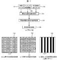
- FIG. 1 is a block diagram showing a configuration of a first embodiment of template matching processing in a pattern matching apparatus included in a measurement / inspection apparatus (hereinafter simply referred to as an inspection apparatus). Matching is performed between the image data 100 of the search area acquired by the inspection apparatus and the design data 101 of the ROI area cut out from the design data of the semiconductor device, and finally the matching position 110 is calculated. Such processing is executed by the matching processing unit 1409.
- a pattern to be searched for in the search target image has a high intensity (or high value) and a low intensity (or low value) edge intensity (or gradation value).
- the purpose is to make it possible to detect the correct correct position even in the case of the above. For this purpose, details will be described later in the description of FIG. 1, but for each of a plurality of matching position candidates obtained by normal matching.
- a similar region having a high intensity (or high value) edge strength (or gradation value) is removed from the image data, and the similarity evaluation with the template is performed on the remaining region of the image data (for example, correlation calculation (non-patent) Document 1 (pp. 1672)) is performed and a matching position candidate having a high degree of similarity is output as a matching position.
- the edge intensity (or gradation value or similarity between the searched image and the template) of the pattern to be searched for is high intensity (or high value) and low intensity (or low value).
- the edge strength of the pattern will be mainly described hereinafter.
- the pixel value or the similarity between the image to be searched and the template can be matched by simply replacing the edge strength. it can.
- noise reduction processing such as Gaussian filter processing and median filter processing (Non-Patent Document 1, pp. 1670) is performed as processing.
- the noise reduction process is not limited to this, and any process that can reduce noise may be used.
- edge emphasis processing is performed to emphasize the pattern shape.
- Sobel filter processing Non-Patent Document 1, pp. 1215
- the edge enhancement processing is not limited to this, and any processing that can perform edge enhancement may be used.
- Both of the noise reduction processing and the edge enhancement processing in the preprocessing of the preprocessing unit A are not necessarily performed, and either one or both of the processing can be omitted.
- Such image processing can be performed by the SEM image processing unit 1420.
- an edge emphasis process is performed to emphasize the shape of the design data pattern.
- Sobel filter processing Non-Patent Document 1, pp. 1215
- the edge enhancement processing is not limited to this, and any processing that can perform edge enhancement may be used.
- the main processing in the preprocessing unit B is not necessarily performed, and the processing may not be executed.
- a template (first template) including multiple layers of information is generated.
- image processing can be performed by a design data image processing unit 1414 provided in the template generation unit 1410.
- the multi-layer template generation unit 1412 generates a template based on the multi-layer pattern data included in the selected design data area.
- the matching processing unit 104 or 1409 uses the first template generated as described above. For example, a matching process using a normalized correlation method (Non-Patent Document 1, pp. 1672) is performed. By this matching processing, the position of the region where the pattern is similar between the template and the searched image can be detected.
- the matching processing unit 104 selects a plurality of items having higher similarity (for example, correlation value). A value may be determined in advance so that the number of selections is a predetermined number, or an index for matching degree determination called a matching score that is greater than or equal to a predetermined value may be selected. Further, a predetermined number (or a predetermined number or more) indicating a degree of coincidence of a predetermined value or more may be determined in advance.
- the selected matching position is the matching position candidate 105, and as described above, the matching position candidate 105 includes a matching correct answer position and an incorrect answer position in many cases.
- the high-intensity similarity region designation processing unit 106 designates a region having the high edge strength described above.
- This high-intensity similarity region is a region having a high similarity between the template and the image to be searched and a high-intensity region, a region having a high similarity and expected to be a high-intensity, or a region including such a region (here, The region including such a region means, for example, a region of a layer having design data including a region having high similarity and high strength.
- Such processing is performed by the region selection unit of the removal processing selection unit 1411.
- the design data of the upper layer pattern having high strength is designated based on the design data.
- the high-intensity similar region removal processing unit 107 converts the region (upper layer pattern 311 in the example of FIG. 3) designated by the previous high-intensity similar region designation processing unit 106 into image data (covered data) corresponding to each matching position candidate.
- the second target image excluding the specific layer information is generated by removing the area from the search image) area (area 300 in the example of FIG. 3). As a result, the above-described high-intensity region (pattern information of the specific layer) can be removed.
- the image data here may be an image that has been preprocessed by the preprocessing unit A102 or an image that is the image data 100 acquired by the inspection apparatus.
- the high-intensity similarity region designation processing unit 106 creates a template on which the lower layer pattern is selectively displayed based on the above selection.
- the lower layer template generation unit 1413 creates a template (second template) in which the lower layer pattern is selectively displayed by excluding the selected pattern based on the selection of the upper layer pattern.
- the above-described high-intensity region or low-intensity region may be automatically determined based on layer information registered in GDS data or the like.
- an input device 1418 sets an image acquisition region on design data, and based on the selection, automatically determines to which layer a pattern included in the acquisition region belongs, and a pattern belonging to the upper layer side, The patterns belonging to the lower layer side may be automatically determined.
- When performing such processing automatically prepare a sequence for classification so that a pattern having upper layer information is an upper layer pattern, and a pattern having lower layer information is a lower layer pattern, Patterns are automatically classified based on image acquisition area settings.
- Such processing may be executed by the layer determination unit 1415 based on the selection by the region selection unit 1411.
- a template other than the removed region is used for the image data (image 331 in the example of FIG. 3) obtained by the previous high-similar region removal processing unit 107. Similarity is evaluated by using a pattern (second template including specific layer information) (lower layer pattern 321 in the example of FIG. 3). Thereby, it is possible to perform similarity evaluation by removing a high-intensity similar region at each matching position candidate, and it is possible to perform similarity evaluation mainly with a low-intensity pattern.
- the matching position selection processing unit 109 compares the similarity at each matching candidate position obtained by the similarity determination processing unit 108 with respect to the image from which the previous high-intensity similar region has been deleted, and matches the candidate with the highest similarity. Output as position 110.
- Such similarity determination may be performed selectively with respect to the extracted matching candidate positions, so that an accurate matching position can be specified with high efficiency.
- Such a similarity determination can be performed by the matching algorithm as described above, and can be performed by the matching processing unit 1409. Further, matching candidate position information may be stored in the memory 1408, and a template for a lower layer pattern may be superimposed on the image based on the position information.
- the similarity determination is performed using the second template in which the lower layer pattern is selectively displayed.
- the similarity determination may be performed using the first template.
- the degree of similarity is relatively low compared to the determination using the second template.
- the second target image is an image from which the upper layer information is removed, even if the upper layer information remains in the template, the degree of similarity between the plurality of matching position candidates is greatly affected. May not be given.
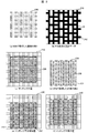
- FIG. 3 shows the design of the ROI region by the high-intensity similar region designation processing unit 106, the high-intensity similar region removal processing unit 107, and the similarity determination processing unit 108 for the image from which the high-intensity similar region has been removed in FIG. It is a figure explaining the 1st method which removes a high intensity
- FIG. 3A is an example of an image 300 acquired by the inspection apparatus. This image is an example of observing a semiconductor device having a multilayer structure, and has a two-layer structure of an upper layer and a lower layer.
- the pattern 301 formed in the upper layer is an example in which the gradation value of the image is higher and the strength of the edge of the pattern is higher than the pattern 302 formed in the lower layer.
- FIG. 3B shows ROI area design data 305, which is a template image.
- the edge strength of the lower layer pattern 302 is weaker than that of the upper layer pattern 301. Therefore, in normal template matching, for example, There is a case where a matching position shift occurs in the lower layer pattern, and a matching correct answer position cannot be obtained (the same reason as the example described in FIG. 2F). Therefore, the upper layer pattern having a high edge strength or a high gradation value is removed.
- 3 (c) and 3 (d) are upper layer pattern design data 310 and lower layer pattern design data 320 for one of the matching position candidates described in FIG.
- the upper layer design data 310 is removed from the image 300 to obtain a high intensity
- An image 331 from which the area has been removed is generated.
- This removal process is performed by the removal processing unit 107 of the high-intensity similar region.
- the method for designating the area to be removed will be described with reference to FIG. 4. For example, when it is known from the properties of the observation image that the intensity of the upper layer pattern becomes high, for example, the upper layer pattern is removed. There are a method of determining in advance as an area and a method of allowing a pattern to be removed from the user to be accepted (an example of a user-set GUI (Graphical User Interface) will be described with reference to FIG. 13). .
- GUI Graphic User Interface
- Similarity evaluation is performed on the image 331 from which the high-intensity area has been removed with a pattern (in this example, the lower layer design data 321) that is design data other than the removed area (for example, a normalized correlation value method is used). Use).
- This similarity evaluation is performed by the similarity determination processing unit 108.
- the similarity evaluation method here is not limited to the normalized correlation method, and may be any method that can evaluate the similarity.
- patterns patterns for similarity evaluation
- the hidden portion is removed. It is also possible to use (removal of the portion overlapping the broken line region interior 322 in FIG. 3D).
- FIGS. 3E and 3F show examples of the matching correct answer position 330 and the matching incorrect answer position 340 included in the matching candidates.
- the lower layer pattern of the image 300 is designed. Although it almost coincides with the lower layer pattern 332 of the data, the lower layer pattern of the image 300 does not coincide with the lower layer pattern 333 of the design data at the incorrect answer position 340.
- a correct matching position can be selected by selecting a candidate having a high similarity calculated by the similarity determination processing unit 108 from the matching candidates.
- the upper layer pattern 301 has high strength and the lower layer pattern 302 has low strength.
- the upper layer pattern 301 is not particularly limited to two layers, and the high strength region is not limited to the upper layer.
- the layer of the high-intensity region is removed, and similarity determination processing is performed in the remaining region.
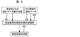
- FIG. 4 is a block diagram showing a configuration of a method for specifying a high-intensity similar region to be removed from the image data 100 by the high-intensity similar region designation processing unit 106 in FIG.
- the following two examples will be described in this specification as a method for designating a high-intensity similarity region.
- One is a method of extracting high-intensity similar regions from the image captured by the inspection device by image processing etc., and the other is advanced before image acquisition from the image acquired by the inspection device and the nature of the observation sample. This is a method for acquiring information of a similar region.
- the former will be described later with reference to FIG.
- the latter includes, for example, a method of accepting information on a region that becomes a highly similar region obtained in advance as a user input, or fixing and setting a highly similar region in the matching process.
- the process of selecting the design data of the layer corresponding to the high intensity from the design data 402 of the ROI region is selected as the high-intensity similarity selection processing unit 403.
- the layer information 401 of the design data having high strength is accepted as a user input as described above, for example, an image obtained by observing a sample with an inspection apparatus (or a shape or composition is similar).
- the image of which the image to be observed can be analogized is presented as an image for the user to specify the layer of the high-intensity region, and the layer of the high-intensity similar region determined by the user based on the image is accepted as input. Do.
- the presentation of the image here is not always necessary, and it is only necessary to accept the layer of the high-intensity similar region as the user's input (in this case, for example, the user can perform the experience or simulation of the past). Judging from the result, etc., a high-intensity similarity region is designated.
- the highly similar region is fixed and set, for example, in the case of an electron microscopic image of a semiconductor pattern, the upper layer pattern often detects more emitted electrons, so the upper layer pattern is a layer with high intensity.
- the sample type material and structure type
- the observation conditions of the device accelerating voltage, probe current, electron detector type (installation position and detection conditions for electron microscopes), and other magnetic field conditions in the device
- the area where the intensity is high may differ. In this case, the area where the intensity is high is set. It will be.
- an acquired image may be calculated by a simulation based on the type of sample and the observation conditions of the apparatus, and the high intensity region may be selected from the image.
- This processing is performed by the high-intensity region designation processing unit 106 in FIG.
- a high-intensity region to be removed by the high-intensity similar region removal processing unit 107 is specified for the image 100 of the inspection apparatus that fails to match due to a mixture of high-intensity and low-intensity regions. be able to.
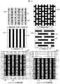
- FIG. 5 is a diagram for explaining a second method for removing a high-intensity similar region from the image data 100 by the highly similar region removal processing unit 107 in FIG.
- the method of removing the highly similar region described above with reference to FIG. 3 is a method of removing all the regions having the layer pattern designated in the design data.
- a method for designating (or extracting) a higher-intensity area from the designated layer based on the design data and removing the designated (or extracted) area from the image data 100 acquired by the inspection apparatus. Is described. This makes it possible to bring the high-intensity similar region to be removed from the image 100 closer to the high-intensity similar region in the actual image, and to avoid deleting the low-intensity region in the designated layer more than necessary. Become.
- the actually formed semiconductor pattern 500 may deviate from the pattern 510 described in the design data (the line width is actually the line pattern).
- the semiconductor pattern 501 and the design data pattern 511 are different from each other), and even when there is such a difference, it is possible to remove only the high-intensity similarity region as much as possible.
- the pattern edge portion has a region 521 (sometimes called a white band) having a wide gradation value. Only the white band 521 is removed as a high-intensity region.
- the layer designated as a high-intensity similar region (this example is an example in which the lower layer pattern 531 in FIG. 5D is a high-intensity similar region)
- the design data of the layer when the pattern 541 of low intensity overlaps or is included in an area where the pattern exists in the actual image (for example, as shown in the area indicated by the broken line in FIG. It is possible to avoid unnecessarily removing the region having the low-intensity pattern in the pattern of layers other than the layer of the strength-similar region.
- the upper layer design data 510 shown in FIG. 5B is designated as a layer of a high-intensity similar region.
- the line width of the line pattern in the SEM image 500 is different from the design data (in this example, the line width is narrowed but may be thickened). Therefore, as shown in FIG. 5G, the line width of the corresponding line pattern is changed (in this example, the line width is narrowed, but it is not limited to narrowing, it is thicker).
- the changing method for example, the number of pixes designated for the line width size is changed (for example, the region is expanded or reduced by image processing).
- the designation of the change size includes a method of accepting a change amount from a user and a method of setting based on a simulation result of a semiconductor process.
- the method of setting the change amount is not limited to this, and any method can be used as long as the change amount equivalent to the image acquired by the actual inspection apparatus can be set.
- the upper layer design data 510 shown in FIG. 5B is designated as a layer of a high-intensity similar region.
- the peripheral region of the pattern edge portion 511 is designated as the high-intensity similarity region.
- FIG. 5F illustrates an example of the designated area 551.
- an area having a width of several pix along the edge portion of the pattern is designated as an area corresponding to the thickness of the white band. The areas other than the designated area are not removed. Thereby, only the white band portion of the high intensity region can be removed.
- the lower layer design data 530 in FIG. 5D is designated as a layer of a high-intensity similar region.
- the region designated as the high-intensity similarity region is a lower layer pattern, and in the SEM image 540, the upper layer pattern 541 overlaps the lower layer pattern, and the lower layer pattern becomes invisible (for example, FIG. 5E). Area surrounded by a broken line).
- a process of removing the lower layer pattern area where the upper layer pattern overlaps in the design data from the area to be removed as the high-intensity similarity area is performed (for example, surrounded by a broken line in FIG. 5 (h)).
- Area the area to be removed is the upper layer pattern and the lower layer pattern in the design data, and the area where the pattern exists in both can be calculated by a logical operation or the like.
- the method for calculating the region to be removed is not limited to this, and any method may be used as long as it is a method for extracting a portion overlapping the high-intensity similar region and other regions.
- the formed semiconductor pattern may deviate from the shape of the design data due to various factors (Patent Document 4). Therefore, a pattern obtained by processing the design data so as to approximate the shape of the semiconductor pattern may be used instead of the design data described above. As an example, a Gaussian filter process is performed on the design data, a contour is extracted from the result, and a shape close to the actual pattern shape is obtained, or an exposure simulation is performed, and the result is analyzed. Then, there is a method of performing contour extraction to obtain a shape close to the actual pattern shape (Patent Document 4).
- each method may be used alone or in combination. In this way, by setting the removal region in accordance with the situation of the high-intensity similar region in the image of the inspection apparatus, it is possible to improve the performance of selecting the correct position in the matching method described in FIG. it can.
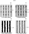
- FIG. 6 is a diagram for explaining a third method for removing a high-intensity similar region from the image data 100 by the highly similar region removal processing unit 107 in FIG.
- the method of removing the highly similar region described above with reference to FIG. 3 or FIG. 5 is a method of removing all of the regions having the layer pattern specified in the design data, or a specific process based on the design data. In this method, the set area is removed by adding.
- a high-intensity area is specified (or extracted) based on both the design data of the specified layer and the image acquired by the inspection apparatus, and the specified (or extracted) area is acquired by the inspection apparatus.
- a method of removing from the image data 100 will be described.
- the high-intensity similar region to be removed from the image data 100 can be brought close to the high-intensity similar region in the actual image, and the removal of the low-intensity region more than necessary by removing the high-intensity similar region is avoided. It will be possible.
- FIG. 6A shows an image acquired by the inspection apparatus, and the upper layer pattern 601 is a high-intensity similar region.
- contour extraction processing for example, Patent Document 1, pp.253, pp.1651
- FIG. 6B shows an example of the result of extracting the contour 612.
- the contour 612 is extracted using the upper layer pattern 611 of the design data as an initial condition.
- a region 621 from which all the region inside the contour is removed is used.
- the method is not limited to changing the width, and all methods described in the explanation of FIG. 5 can be used. Thereby, in the matching method demonstrated in FIG. 1, the performance of selecting a correct position can be improved.
- FIG. 7 is a block diagram showing a configuration of a second method for designating a high-intensity similar region to be removed from the image data 100 by the high-intensity similar region designation processing unit 106 described in FIG. FIG.
- the method described above with reference to FIG. 3 is a method for acquiring information on a highly similar region before image acquisition from the image acquired by the inspection apparatus and the properties of the observation sample.
- a method for extracting a high-intensity similar region from an image captured by an inspection apparatus by image processing will be described.
- This method is a method in which an area for evaluating the strength is set for each layer of the design data, and the area having the highest intensity is removed from each evaluation area.
- FIG. 7A is a block diagram of the configuration of this method.
- an intensity evaluation area based on each layer of the design data is set, and an index value for evaluating the intensity for each layer is calculated 704.
- a layer having high strength is selected 705 from the result, and the selected region is set as a high strength similar region 706.
- This example is a two-layer semiconductor pattern.
- FIG. 7B shows an example in which the upper layer pattern evaluation area 711 is set to an image acquired by the inspection apparatus
- FIG. 7C shows the lower layer pattern evaluation area 721 of the image acquired by the inspection apparatus.
- the evaluation index value of intensity is calculated in the evaluation area 711 of the upper layer pattern and the evaluation area 721 of the lower layer pattern, respectively.
- the index value for example, an average value of edge strength in the evaluation region, an average pixel value, or a correlation value between an image acquired by the apparatus and a template is used.
- the index value having the higher intensity is selected 730 as the high intensity similarity region.
- the evaluation index is not limited to the index shown here, but may be an index value that allows comparison of strength.
- the evaluation index value in each layer is similarly calculated for the pattern of the structure of 3 layers or more by setting an evaluation area in each layer, It is possible to select a high-intensity similarity region from the evaluation index value.
- a high-intensity similar region can be extracted from an image captured by the inspection apparatus by image processing.
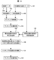
- FIG. 9 is a block diagram showing the configuration of another embodiment of the template matching process.
- a processing 900 for a high-strength similar region is performed.
- the high-intensity similar region is removed by the removal processing unit 107 from the image acquired by the inspection apparatus.
- the region removed may have pattern information of layers other than the layer intended to be removed. This is the case, for example, when the layers under the removed layer are seen through and the pattern is on the removed layer. If information on layers other than the high-intensity similar region is also removed as described above, there is a risk that the correct matching position cannot be selected by the matching method described in FIG. 1 due to the lost information.
- the corresponding area is processed to reduce the high-intensity information while leaving the pattern information of other layers. (A specific example will be described with reference to FIG. 10). Accordingly, in the method of FIG. 1, some or all of the information that has been removed from the image data 100 acquired by the inspection apparatus remains, so that the matching correct position selection performance in the similarity determination processing 108 and the matching position selection processing 109. Can be improved.
- the input is the image data 100 acquired by the inspection apparatus and the design data of the ROI area.
- processing for reducing the influence of noise included in the image on the matching processing is performed.
- noise reduction processing such as Gaussian filter processing and median filter processing (Non-Patent Document 1, pp. 1670) is performed as processing.
- the noise reduction process is not limited to this, and any process that can reduce noise may be used.
- edge emphasis processing is performed to emphasize the pattern shape.
- Sobel filter processing Non-Patent Document 1, pp. 1215
- the edge enhancement processing is not limited to this, and any processing that can perform edge enhancement may be used.
- Both the noise reduction process and the edge enhancement process in the pre-processing of the pre-processing unit A are not necessarily performed, and either one or both processes may not be performed.
- an edge enhancement process is performed in order to enhance the shape of the pattern of the design data. For example, Sobel filter processing (Non-Patent Document 1, pp. 1215) is performed. Note that the edge enhancement processing is not limited to this, and any processing that can perform edge enhancement may be used.
- the matching processing unit 104 performs template matching (Non-Patent Document 1, pp. 1670). For example, a matching process using a normalized correlation method (Non-Patent Document 1, pp. 1672) is performed. By this matching processing, the position of the region where the pattern is similar between the template and the searched image can be detected.
- the matching processing unit 106 selects a plurality of items having higher similarity (for example, correlation value).
- the selected matching position is the matching position candidate 105, and as described above, the matching position candidate includes a matching correct answer position and an incorrect answer position in many cases.
- the high-intensity similarity region designation processing unit 106 designates a region having the high edge strength described above.
- This high-intensity similarity region is a region having a high similarity between the template and the image to be searched and a high-intensity region, a region having a high similarity and expected to be a high-intensity, or a region including such a region (here, The region including such a region means, for example, a region of a layer having design data including a region having high similarity and high strength.
- the high-intensity similar region processing unit 900 processes the region specified by the previous high-intensity similar region designation processing unit 106 into the region of image data (searched image) corresponding to each matching position candidate.
- image data here may be an image that has been preprocessed by the preprocessing unit A102 or an image that is the image data 100 acquired by the inspection apparatus.
- the similarity determination processing unit 108 for the image obtained by processing the high-intensity similar region uses the template pattern other than the removed region to determine the similarity for the image data obtained by the previous high-intensity similar region removal processing unit 107. Evaluate. Accordingly, it is possible to perform similarity evaluation by processing a high-intensity similar region with each matching position candidate, and it is possible to perform similarity evaluation mainly with a low-intensity pattern.
- the matching position selection processing unit 109 compares the similarity at each matching candidate position obtained by the similarity determination processing unit 108 with respect to the image from which the previous high-intensity similar region has been deleted, and matches the candidate with the highest similarity. Output as position 110. As described above, it is possible to determine an exact matching position by template matching even in the case where a high intensity and a low intensity are mixed in the search target pattern shown in the search target image. .
- FIG. 10 is a diagram for explaining a method of processing the high-strength similar region by the processing unit 900 for the high-strength similar region described in FIG. 9.
- FIG. 10A shows an example of the image data 1000 acquired by the inspection apparatus.
- This multi-layer sample has a two-layer structure, and the upper layer pattern 1001 is a high-strength region. Therefore, the high-strength similar region to be processed is the upper layer pattern 1011 in the design data shown in FIG.
- FIG. 10C shows an example of the processing result.
- the processing region 1011 is interpolated with pixel values in the region around the processing region, and the pixel values in the processing region are filled (in this example, interpolation is performed with pixel values adjacent to the left and right of the processing region). Is).
- the image data interpolation method is described in, for example, Patent Document pp. 1360.
- information on adjacent patterns other than the pattern of the high-intensity region in the high-intensity region can be estimated from information around the high-intensity region, and the high-intensity region can be filled (interpolated) with the information.
- an image in which the information of the high-intensity region is reduced by performing processing for relatively reducing the information of the high-intensity region (in this example, the upper layer pattern) with respect to the original image is used. Similarity determination can be performed.
- FIGS. 10D and 10E are diagrams for explaining a method of processing by a method different from the method of interpolating with the adjacent pixels described above.
- the processing region high-intensity similar region
- FIG. 10D shows an example of the weight.
- the processing area 1031 is weighted smaller than the area 1032 other than the processing area.
- the strength of 1041 that is a high-intensity similar region can be weakened.
- the weight here is not limited to a uniform value, and can be multivalued.
- a high-strength similar region for the two-layer structure pattern has been described. However, this is not limited to two layers, and the same processing may be performed for three or more layers.
- a high-strength similar region can be processed by the method as described above.
- FIG. 11 is a block diagram showing a configuration of still another embodiment of the template matching process.
- the template is not design data but an image 1001 acquired by an inspection apparatus.
- the design data is not used in the high-intensity similar region designation processing unit 1103, and the removal / processing of the high similarity region is performed on both the searched image and the template in FIG. 1 and FIG. Different from the method.
- a high-intensity similar region designation method in the high-intensity similar region designation processing unit 1103 will be described with reference to FIG.
- the input is template image data 1101 acquired by the inspection apparatus to form a template, and searched image data 100 acquired by the inspection apparatus.
- processing for reducing the influence of noise included in the image on the matching processing is performed.
- noise reduction processing such as Gaussian filter processing and median filter processing (Non-Patent Document 1, pp. 1670) is performed as processing.
- the noise reduction process is not limited to this, and any process that can reduce noise may be used.
- edge emphasis processing is performed to emphasize the pattern shape.
- Sobel filter processing (Non-patent Document 1, pp. 1215) is performed.
- edge enhancement processing is not limited to this, and any processing that can perform edge enhancement may be used. Both of the noise reduction processing and the edge enhancement processing in the preprocessing of the preprocessing sections A and B are not necessarily performed, and either one or both processing may not be performed. It is.
- the matching processing unit 104 performs template matching (Non-Patent Document 1, pp. 1670).
- Non-Patent Document 1 pp. 1672
- the matching processing unit 106 selects a plurality of items having higher similarity (for example, correlation value).
- the selected matching position is the matching position candidate 105, and as described above, the matching position candidate includes a matching correct answer position and an incorrect answer position in many cases.
- the high-intensity similarity region designation processing unit 1103 designates the region having the high edge strength described above.
- the high-intensity similar region removal / processing unit 1102 uses the region specified by the previous high-intensity similar region designation processing unit 106 as a region of image data (searched image and template image) corresponding to each matching position candidate. Is removed / processed.
- image data here may be an image pre-processed by the pre-processing units A 102 and B, or an image as it is, the image data 100 and 1101 acquired by the inspection apparatus.
- the similarity determination processing unit 108 for the image from which the high-intensity similar region is removed / processed performs processing / processing of the previous high-intensity similar region with respect to the searched image that has been processed by the processing / removal processing unit 107 in the previous high-intensity similar region.
- the similarity is evaluated using the template that has been subjected to the removal processing unit 107. Accordingly, it is possible to perform similarity evaluation by removing / processing a high-intensity similar region at each matching position candidate, and it is possible to perform similarity evaluation mainly with a low-intensity pattern.
- the matching position selection processing unit 109 compares the similarity at each matching candidate position obtained by the similarity determination processing unit 108 with respect to the image from which the previous high-intensity similar region has been deleted, and matches the candidate with the highest similarity. Output as position 110. As described above, even if the search target pattern shown in the search target image and the search target pattern shown in the template have both high and low edge strength, the template matching is accurate. It becomes possible to determine the matching position.
- FIG. 12 shows a method for specifying a high-intensity similar region and a processing / removal of a high-intensity similar region in the high-intensity similar region designation processing unit 1103 and the high-intensity similar region processing / removal processing unit 1102 described in FIG. It is a figure explaining the method to do.
- the high-intensity similarity region is specified by extracting from the image 1200 acquired by the inspection apparatus without using design data.
- the high-intensity region is, for example, a region where the edge strength is high or the pixel value is high.
- the former region having a high edge strength may be obtained by performing an appropriate binarization process (Non-Reference 1) on the edge image of the image 1200 to extract a region corresponding to the higher value, and the latter pixel value.
- the image 1200 may be binarized to extract a region corresponding to a higher value.
- the method of extracting a region having a high edge intensity or a high pixel value is not limited to the binarization process, and any method can be used as long as the corresponding region can be extracted.
- the region 1211 shown in the image 1210 in FIG. 12C is the region 1211 shown in the image 1210 in FIG. As shown in FIG. 12C, the region 1211 as it is can be designated as the region 1221 to be removed / processed. Further, as described in FIG. 6, the outline of the area 1211 is extracted, and all 1241 inside the area or the area where the outline is thickened by a specified width is designated as the area to be processed / removed. You can also. Further, when processing a highly similar region, interpolation processing or weighting processing may be performed as described with reference to FIG. Accordingly, the high-intensity similar region designation processing unit 1103 and the high-intensity similar region processing / removal processing unit 1102 described in FIG. 11 are designated, and the high-intensity similar region is processed / removed. Is possible.
- FIG. 13 is a diagram for explaining an example of a GUI that makes it possible to accept from the user the setting method of the removal / processing region when removing / processing the high-intensity similar region, and the setting of the removal method.
- This figure is displayed on the display device 820 of the inspection apparatus that can perform high-intensity similarity region removal / processing on the matching candidates obtained by the matching processing and select a matching correct position by the similarity determination processing. It is an example of GUI1300 to be performed.
- the check box 1301 it is possible to select whether or not to perform the selection of the correct matching position by the high intensity similarity region removal / processing process and the similarity determination process described in this specification.
- the selection box 1302 or 1312 can be used to select whether the measurement data-device image matching or the device image-device image matching.
- the removal / processing area setting method and the setting of the removal method can be received from the user.
- the input box 1319 can receive the input of the layer in the design data to be removed / processed from the user (using the method described in FIG. 4). is there).
- the selection box 1304 is selected, the design data layer to be removed / processed can be automatically selected (the method described with reference to FIG. 7). Further, the removal / processing area correction setting can be accepted from the user, and when the check box 1306 is selected, the area to be removed / processed can be manually designated or edited.
- This designation and editing can be performed while confirming the area in the display area 1323 of the high-intensity similar area.
- the extracted area can be expanded or reduced by a value (for example, set in pix units) input to the input box 1321.
- a selection box 1307 an area can be set by contour extraction processing (the method described with reference to FIG. 6). Further, details of the removal / processing area can be received from the user.
- the selection box 1308 is selected, a method of making the entire area a removal / processing area can be selected (the method described in FIG. 3), and the selection box 1326 is selected. If selected, a method of removing / processing the periphery of the edge of the region can be selected (the method described in FIG. 5).
- the input of the area width (for example, set in pix) can be accepted in the input box 1322.
- a removal or processing method can be selected.
- the selection box 1309 it is possible to select to remove the high-intensity region (the method described in FIG. 3).
- the selection box 1310 is selected, the high-intensity region can be interpolated with adjacent pixels (the method described in FIG. 10).
- weighting processing can be performed on the high-intensity region (the method described with reference to FIG. 10).
- the setting method of the removal / processing area and the setting of the removal method can be received from the user.
- a high-strength layer can be automatically selected (the method described with reference to FIG. 12).
- the selection box 1314 is selected, the area can be manually designated and processed. This designation and processing can be performed while confirming the area in the high-intensity similar area display area 1323.
- a removal or processing method can be selected.
- the selection box 1315 is selected, the high-intensity region can be removed (this method is the method described in FIG. 3).
- the high-intensity region can be complemented with adjacent pixels (the method described in FIG. 10).
- weighting processing can be performed on the high-intensity region (the method described with reference to FIG. 10).
- the GUI does not have to have all the members listed here, and is provided with all or part of the GUI.
- FIG. 15 is a diagram for explaining an example in which a low contrast region such as a lower layer pattern is selected as an image for similarity determination.
- 15 (a) and 15 (b) are the same as FIGS. 6 (a) and 6 (b).
- a selection area 1521 is selected, and an image 1531 for similarity determination is formed based on this selection. Also by such a method, it becomes possible to specify the exact matching position while suppressing the influence of the high intensity region.
- FIG. 15 (e) is a diagram for explaining an example in which a region where a pattern is present is selectively extracted from low-intensity regions. Rather than using all the selected areas for similarity determination, the matching position can be accurately identified even if an image is formed based on an area where a pattern exists.
- FIG. 16 is a flowchart showing a process of determining a matching position based on a plurality of pattern matching processes. The difference from the pattern matching method described in FIG. 1 and the like is that the second pattern matching is performed using the lower layer template after removing the removal region from the image.
- step 1601 based on the setting of an arbitrary area on the design data, information necessary for template creation is read from the storage medium (design data storage medium 1417 or memory 1408) (step 1601). Based on the read design data, a multi-layer template used for the first pattern matching is created (step 1604) and a lower layer template used for the second template matching is created (step 1602). Further, an excluded area of the image for performing the second pattern matching is selected (step 1603).
- step 1605 an image to be subjected to pattern matching is acquired (step 1605), and pattern matching using the multi-layer template created in step 1604 is executed (step 1606).
- a preset matching score threshold value predetermined value
- An error message is generated with processing. If the number m of matching positions is 1, the matching process is terminated, assuming that there is one correct position, that is, the final matching position has been identified. Since the sample is charged and the resolution of the image is low, the number of matching positions may be only one. In this case, an error message or the like may be generated. You may make it change correspondence according to the condition and measurement environment of a sample.
- the process proceeds to the next step.
- a threshold value may be set for the number of matching positions, and the top m matching positions with high scores may be specified.
- the removal area selected in step 1603 is removed from the SEM image acquired in step 1605 to generate a removal image (step 1607).
- the removal region is a region set so as to cover the contour of the upper layer pattern, and a region slightly larger than the contour of the upper layer pattern may be used as the removal region.
- Pattern removal using the lower layer template created in step 1602 is executed on the removed image thus formed (step 1608). That is, in the flowchart illustrated in FIG. 16, the degree of coincidence determination based on pattern matching is performed between an image from which upper layer pattern information has been removed and a lower layer pattern selectively extracted and a lower layer template in which no upper layer pattern exists. Is done.
- n of matching positions in step 1608 If the number n of matching positions in step 1608 is 0, an appropriate lower layer pattern could not be detected, and an error message is generated. If n is 1, the matching process is terminated under the condition that the matching position has been properly specified under the condition that the matching position has also been specified in the pattern matching in step 1606. If the matching position in step 1608 and the matching position in step 1608 do not match, an error message is generated based on the determination that matching has not been performed properly.
- step 1608 If the number n of matching positions in step 1608 is plural (n> 1), the number o of matching positions specified in both step 1606 and step 1608 is determined. If o is 1, appropriate matching is performed. Assuming that there is one position, the matching process is terminated. When o is plural (o> 1), there are a plurality of matching position candidates. Therefore, in order to select an appropriate one, the position having the maximum matching score in step 1606 or step 1608, or The position where the multiplication value of the matching degree of both the matchings and the added value of the matching score is maximized is determined as the matching position (step 1609).
- FIG. 17 is also a flowchart showing a process of determining a matching position based on a plurality of pattern matching processes, as in FIG. 16, and in the process illustrated in FIG. 17 in particular, there is an overlay error between the upper layer pattern and the lower layer pattern. Even in some cases, the main purpose is to execute pattern matching appropriately.
- Steps 1701 to 1703 are substantially the same as steps 1601 to 1608. If the number p of matching positions specified by both of the two matches is zero, an error message is generated as the matching was not properly performed (step 1704). If the number p is 1, if the matching position between the two is equal to or less than a predetermined threshold value, the matching is terminated because the matching is successful (step 1705). If the distance between the matching positions exceeds a predetermined threshold, it is assumed that a matching failure or a gap between layers (overlay error) has occurred, and an output for displaying that fact on the display device is performed. (Step 1706).
- the position specified by the first pattern matching is the position specified as a result of being strongly influenced by the upper layer pattern
- the position specified by the second pattern matching is the lower layer. This is a position corresponding to the position of the pattern. Therefore, the deviation (shift amount) between the two can be defined as an overlay error.
- step 1708 when the number p of matching positions is larger than 1 (p> 1), the one having the closest distance between the two matching positions is selected, or the distance between the two matching positions satisfies a predetermined condition (for example, after selecting (below the threshold value) (step 1708), processing equivalent to steps 1705 and 1706 is executed.
Landscapes
- Engineering & Computer Science (AREA)
- Physics & Mathematics (AREA)
- General Physics & Mathematics (AREA)
- Theoretical Computer Science (AREA)
- Computer Vision & Pattern Recognition (AREA)
- Quality & Reliability (AREA)
- Multimedia (AREA)
- Biochemistry (AREA)
- Chemical & Material Sciences (AREA)
- Analytical Chemistry (AREA)
- Life Sciences & Earth Sciences (AREA)
- General Health & Medical Sciences (AREA)
- Immunology (AREA)
- Pathology (AREA)
- Health & Medical Sciences (AREA)
- Image Analysis (AREA)
- Testing Or Measuring Of Semiconductors Or The Like (AREA)
- Image Processing (AREA)
- Analysing Materials By The Use Of Radiation (AREA)
- Length-Measuring Devices Using Wave Or Particle Radiation (AREA)
Abstract
Description
得る方法がある(特許文献4)。
802 ステージ
803 半導体ウェーハ
804 偏向器
805 対物レンズ
806 二次電子検出器
807,809,810,812 A/D変換器
808 反射電子検出器
811 光学式カメラ
Claims (14)
- 設計データ、或いは撮像画像に基づいて形成されたテンプレートを用いて、画像上でパターンマッチングを実行する画像処理部を備えたパターンマッチング装置において、
前記画像処理部は、異なる複数のパターンを含む第1のテンプレートを用いて、第1の対象画像に対するパターンマッチングを実行し、当該第1の対象画像から、複数のパターンの内、特定パターンを含む領域の情報を除外、或いは特定パターンの情報を低減して第2の対象画像を作成し、当該第2の対象画像と、前記特定パターン以外のパターン情報を含む、或いは特定パターンの情報を低減した第2のテンプレート、又は前記第1のテンプレートとの間の類似度判定を行うことを特徴とするパターンマッチング装置。 - 請求項1において、
前記画像処理部は、前記第1の対象画像に対するパターンマッチングによって、パターンマッチングの位置候補を抽出し、当該候補の中から、上記類似度判定に基づいて、特定の位置を選択することを特徴とするパターンマッチング装置。 - 請求項2において、
前記画像処理部は、前記特定の位置として前記候補の中から、最も類似度が高いものを選択することを特徴とするパターンマッチング装置。 - 請求項1において、
前記特定パターンは、前記第1の対象画像に表示されたその他のパターンに対し、上層に位置することを特徴とするパターンマッチング装置。 - 請求項1において、
前記特定パターンは、前記第1の対象画像に表示されたその他のパターンに対し、高い信号強度を有することを特徴とするパターンマッチング装置。 - 請求項1において、
前記画像処理部は、前記第1の対象画像に含まれるパターンのエッジに沿った所定の幅を持った領域を除外、或いは当該領域内の情報を低減して、前記第2の対象画像を生成することを特徴とするパターンマッチング装置。 - 請求項6において、
前記画像処理部は、前記エッジに沿った輪郭線内の領域の情報を除外、或いは低減することを特徴とするパターンマッチング装置。 - 設計データ、或いは撮像画像に基づいて形成されたテンプレートを用いて、画像上でパターンマッチングをコンピューターに実行させるコンピュータープログラムにおいて、
当該プログラムは、前記コンピューターに、異なる複数のパターンを含む第1のテンプレートを用いて、第1の対象画像に対するパターンマッチングを実行させ、当該第1の対象画像から、複数のパターンの内、特定パターンを含む領域の情報を除外、或いは特定パターンの情報を低減して第2の対象画像を作成させ、当該第2の対象画像と、前記特定パターン以外のパターン情報を含む、或いは特定パターンの情報を低減した第2のテンプレート、又は前記第1のテンプレートとの間の類似度判定を実施させることを特徴とするコンピュータープログラム。 - 請求項8において、
前記プログラムは、前記コンピューターに、前記第1の対象画像に対するパターンマッチングによって、パターンマッチングの位置候補を抽出させ、当該候補の中から、上記類似度判定に基づいて、特定の位置を選択させることを特徴とするコンピュータープログラム。 - 請求項9において、
前記プログラムは、前記コンピューターに、前記特定の位置として前記候補の中から、最も類似度が高いものを選択させることを特徴とするコンピュータープログラム。 - 請求項8において、
前記特定パターンは、前記第1の対象画像に表示されたその他のパターンに対し、上層に位置することを特徴とするコンピュータープログラム。 - 請求項8において、
前記特定パターンは、前記第1の対象画像に表示されたその他のパターンに対し、高い信号強度を有することを特徴とするコンピュータープログラム。 - 請求項8において、
前記プログラムは、前記コンピューターに、前記第1の対象画像に含まれるパターンのエッジに沿った所定の幅を持った領域を除外、或いは当該領域内の情報を低減して、前記第2の対象画像を生成させることを特徴とするコンピュータープログラム。 - 請求項13において、
前記プログラムは、前記コンピューターに、前記エッジに沿った輪郭線内の領域の情報を除外、或いは低減させることを特徴とするコンピュータープログラム。
Priority Applications (2)
| Application Number | Priority Date | Filing Date | Title |
|---|---|---|---|
| KR1020137022097A KR101523159B1 (ko) | 2011-02-25 | 2011-12-12 | 패턴 매칭 장치 및 컴퓨터 프로그램을 기록한 기록 매체 |
| US14/001,376 US20140016854A1 (en) | 2011-02-25 | 2011-12-12 | Pattern matching device and computer program |
Applications Claiming Priority (2)
| Application Number | Priority Date | Filing Date | Title |
|---|---|---|---|
| JP2011039187A JP5639925B2 (ja) | 2011-02-25 | 2011-02-25 | パターンマッチング装置、及びコンピュータープログラム |
| JP2011-039187 | 2011-02-25 |
Publications (1)
| Publication Number | Publication Date |
|---|---|
| WO2012114410A1 true WO2012114410A1 (ja) | 2012-08-30 |
Family
ID=46720232
Family Applications (1)
| Application Number | Title | Priority Date | Filing Date |
|---|---|---|---|
| PCT/JP2011/006906 Ceased WO2012114410A1 (ja) | 2011-02-25 | 2011-12-12 | パターンマッチング装置、及びコンピュータープログラム |
Country Status (4)
| Country | Link |
|---|---|
| US (1) | US20140016854A1 (ja) |
| JP (1) | JP5639925B2 (ja) |
| KR (1) | KR101523159B1 (ja) |
| WO (1) | WO2012114410A1 (ja) |
Cited By (1)
| Publication number | Priority date | Publication date | Assignee | Title |
|---|---|---|---|---|
| WO2020195304A1 (ja) * | 2019-03-22 | 2020-10-01 | Tasmit株式会社 | パターンマッチング方法 |
Families Citing this family (21)
| Publication number | Priority date | Publication date | Assignee | Title |
|---|---|---|---|---|
| JP5639797B2 (ja) * | 2010-07-01 | 2014-12-10 | 株式会社日立ハイテクノロジーズ | パターンマッチング方法,画像処理装置、及びコンピュータプログラム |
| JP6002480B2 (ja) * | 2012-07-06 | 2016-10-05 | 株式会社日立ハイテクノロジーズ | オーバーレイ誤差測定装置、及びパターン測定をコンピューターに実行させるコンピュータープログラム |
| JP5998068B2 (ja) * | 2013-01-21 | 2016-09-28 | 株式会社日立ハイテクノロジーズ | 画像処理装置、測定システム、画像処理プログラム |
| JP6143337B2 (ja) * | 2013-04-01 | 2017-06-07 | 株式会社ディスコ | キーパターン検出方法、及び、アライメント方法 |
| US20160070985A1 (en) * | 2013-05-02 | 2016-03-10 | Konica Minolta Inc. | Image processing apparatus, image processing method, and storage medium storing image processing program thereon |
| US9158996B2 (en) * | 2013-09-12 | 2015-10-13 | Kabushiki Kaisha Toshiba | Learning image collection apparatus, learning apparatus, and target object detection apparatus |
| KR102078809B1 (ko) * | 2013-10-08 | 2020-02-20 | 삼성디스플레이 주식회사 | 패턴의 선폭 측정 장치 및 그 방법 |
| JP2017126398A (ja) * | 2014-04-16 | 2017-07-20 | 株式会社日立ハイテクノロジーズ | 荷電粒子線装置 |
| US9524540B2 (en) * | 2014-07-22 | 2016-12-20 | Adobe Systems Incorporated | Techniques for automatically correcting groups of images |
| KR101923941B1 (ko) * | 2014-09-11 | 2019-02-25 | 주식회사 엘지화학 | 광학용 점착 시트 |
| US9530199B1 (en) * | 2015-07-13 | 2016-12-27 | Applied Materials Israel Ltd | Technique for measuring overlay between layers of a multilayer structure |
| JP6423777B2 (ja) * | 2015-11-06 | 2018-11-14 | 日本電信電話株式会社 | 信号探索装置、方法、及びプログラム |
| WO2018016062A1 (ja) * | 2016-07-22 | 2018-01-25 | 株式会社 日立ハイテクノロジーズ | パターン評価装置 |
| US20180225799A1 (en) * | 2017-02-03 | 2018-08-09 | Cognex Corporation | System and method for scoring color candidate poses against a color image in a vision system |
| JP6806655B2 (ja) * | 2017-10-10 | 2021-01-06 | 株式会社日立製作所 | 放射線撮像装置、画像データ処理装置及び画像処理プログラム |
| JP7001494B2 (ja) * | 2018-02-26 | 2022-01-19 | 株式会社日立ハイテク | ウェハ観察装置 |
| US10332367B1 (en) * | 2018-10-17 | 2019-06-25 | Capital One Services, Llc | Systems and methods for using haptic vibration for inter device communication |
| EP3987438B1 (en) | 2019-06-24 | 2025-12-17 | Alarm.com Incorporated | Dynamic video exclusion zones for privacy |
| KR102690867B1 (ko) * | 2020-02-20 | 2024-08-05 | 주식회사 히타치하이테크 | 패턴 매칭 장치, 패턴 측정 시스템 및 비일시적 컴퓨터 가독 매체 |
| CN114202578A (zh) * | 2020-09-18 | 2022-03-18 | 长鑫存储技术有限公司 | 一种晶圆的对准方法和装置 |
| JP2024047481A (ja) * | 2022-09-26 | 2024-04-05 | 株式会社日立ハイテク | 半導体観察システムおよびオーバーレイ計測方法 |
Citations (3)
| Publication number | Priority date | Publication date | Assignee | Title |
|---|---|---|---|---|
| JP2008065458A (ja) * | 2006-09-05 | 2008-03-21 | Hitachi High-Technologies Corp | 類似度分布を利用したテンプレートマッチング方法を用いた検査装置 |
| JP2009037375A (ja) * | 2007-08-01 | 2009-02-19 | Pioneer Electronic Corp | 除去対象標示体認識装置、除去対象標示体認識方法及び除去対象標示体認識プログラム |
| JP2010086925A (ja) * | 2008-10-03 | 2010-04-15 | Hitachi High-Technologies Corp | パターンマッチング方法、及び画像処理装置 |
-
2011
- 2011-02-25 JP JP2011039187A patent/JP5639925B2/ja active Active
- 2011-12-12 WO PCT/JP2011/006906 patent/WO2012114410A1/ja not_active Ceased
- 2011-12-12 US US14/001,376 patent/US20140016854A1/en not_active Abandoned
- 2011-12-12 KR KR1020137022097A patent/KR101523159B1/ko active Active
Patent Citations (3)
| Publication number | Priority date | Publication date | Assignee | Title |
|---|---|---|---|---|
| JP2008065458A (ja) * | 2006-09-05 | 2008-03-21 | Hitachi High-Technologies Corp | 類似度分布を利用したテンプレートマッチング方法を用いた検査装置 |
| JP2009037375A (ja) * | 2007-08-01 | 2009-02-19 | Pioneer Electronic Corp | 除去対象標示体認識装置、除去対象標示体認識方法及び除去対象標示体認識プログラム |
| JP2010086925A (ja) * | 2008-10-03 | 2010-04-15 | Hitachi High-Technologies Corp | パターンマッチング方法、及び画像処理装置 |
Cited By (1)
| Publication number | Priority date | Publication date | Assignee | Title |
|---|---|---|---|---|
| WO2020195304A1 (ja) * | 2019-03-22 | 2020-10-01 | Tasmit株式会社 | パターンマッチング方法 |
Also Published As
| Publication number | Publication date |
|---|---|
| JP2012177961A (ja) | 2012-09-13 |
| US20140016854A1 (en) | 2014-01-16 |
| KR101523159B1 (ko) | 2015-05-26 |
| JP5639925B2 (ja) | 2014-12-10 |
| KR20130117862A (ko) | 2013-10-28 |
Similar Documents
| Publication | Publication Date | Title |
|---|---|---|
| JP5639925B2 (ja) | パターンマッチング装置、及びコンピュータープログラム | |
| JP5568277B2 (ja) | パターンマッチング方法、及びパターンマッチング装置 | |
| JP5075646B2 (ja) | 半導体欠陥検査装置ならびにその方法 | |
| JP6134366B2 (ja) | 画像処理装置およびコンピュータプログラム | |
| KR101764658B1 (ko) | 결함 해석 지원 장치, 결함 해석 지원 장치에 의해 실행되는 프로그램 및 결함 해석 시스템 | |
| JP5313939B2 (ja) | パターン検査方法、パターン検査プログラム、電子デバイス検査システム | |
| JP5543872B2 (ja) | パターン検査方法およびパターン検査装置 | |
| JP4586051B2 (ja) | 走査型電子顕微鏡 | |
| US9341584B2 (en) | Charged-particle microscope device and method for inspecting sample using same | |
| JP5988615B2 (ja) | 半導体評価装置、及びコンピュータープログラム | |
| WO2012101717A1 (ja) | パターンマッチング装置、及びコンピュータープログラム | |
| KR20130108413A (ko) | 하전 입자선 장치 | |
| JP2016139467A (ja) | 試料観察方法および試料観察装置 | |
| US9521372B2 (en) | Pattern measuring apparatus, pattern measuring method, and computer-readable recording medium on which a pattern measuring program is recorded | |
| JP2007047930A (ja) | 画像処理装置及び検査装置 | |
| JP5478681B2 (ja) | 半導体欠陥検査装置ならびにその方法 | |
| JP2013140468A (ja) | パターンマッチング装置、検査システム、及びコンピュータプログラム | |
| JP2011192766A (ja) | 半導体ウェーハの外観検査方法及びその装置 | |
| JP2021140693A (ja) | 試験片上の欠陥検出の方法およびそのシステム | |
| WO2015159792A1 (ja) | 荷電粒子線装置 |
Legal Events
| Date | Code | Title | Description |
|---|---|---|---|
| 121 | Ep: the epo has been informed by wipo that ep was designated in this application |
Ref document number: 11859416 Country of ref document: EP Kind code of ref document: A1 |
|
| ENP | Entry into the national phase |
Ref document number: 20137022097 Country of ref document: KR Kind code of ref document: A |
|
| NENP | Non-entry into the national phase |
Ref country code: DE |
|
| WWE | Wipo information: entry into national phase |
Ref document number: 14001376 Country of ref document: US |
|
| 122 | Ep: pct application non-entry in european phase |
Ref document number: 11859416 Country of ref document: EP Kind code of ref document: A1 |