WO2012111710A1 - Outil de coupe - Google Patents
Outil de coupe Download PDFInfo
- Publication number
- WO2012111710A1 WO2012111710A1 PCT/JP2012/053541 JP2012053541W WO2012111710A1 WO 2012111710 A1 WO2012111710 A1 WO 2012111710A1 JP 2012053541 W JP2012053541 W JP 2012053541W WO 2012111710 A1 WO2012111710 A1 WO 2012111710A1
- Authority
- WO
- WIPO (PCT)
- Prior art keywords
- insert
- cutting edge
- cutting tool
- cutting
- holder
- Prior art date
Links
Images


Classifications
-
- B—PERFORMING OPERATIONS; TRANSPORTING
- B23—MACHINE TOOLS; METAL-WORKING NOT OTHERWISE PROVIDED FOR
- B23B—TURNING; BORING
- B23B27/00—Tools for turning or boring machines; Tools of a similar kind in general; Accessories therefor
- B23B27/14—Cutting tools of which the bits or tips or cutting inserts are of special material
- B23B27/16—Cutting tools of which the bits or tips or cutting inserts are of special material with exchangeable cutting bits or cutting inserts, e.g. able to be clamped
-
- B—PERFORMING OPERATIONS; TRANSPORTING
- B23—MACHINE TOOLS; METAL-WORKING NOT OTHERWISE PROVIDED FOR
- B23B—TURNING; BORING
- B23B27/00—Tools for turning or boring machines; Tools of a similar kind in general; Accessories therefor
- B23B27/007—Tools for turning or boring machines; Tools of a similar kind in general; Accessories therefor for internal turning
-
- B—PERFORMING OPERATIONS; TRANSPORTING
- B23—MACHINE TOOLS; METAL-WORKING NOT OTHERWISE PROVIDED FOR
- B23B—TURNING; BORING
- B23B27/00—Tools for turning or boring machines; Tools of a similar kind in general; Accessories therefor
- B23B27/14—Cutting tools of which the bits or tips or cutting inserts are of special material
-
- B—PERFORMING OPERATIONS; TRANSPORTING
- B23—MACHINE TOOLS; METAL-WORKING NOT OTHERWISE PROVIDED FOR
- B23B—TURNING; BORING
- B23B29/00—Holders for non-rotary cutting tools; Boring bars or boring heads; Accessories for tool holders
- B23B29/04—Tool holders for a single cutting tool
-
- B—PERFORMING OPERATIONS; TRANSPORTING
- B23—MACHINE TOOLS; METAL-WORKING NOT OTHERWISE PROVIDED FOR
- B23B—TURNING; BORING
- B23B31/00—Chucks; Expansion mandrels; Adaptations thereof for remote control
- B23B31/005—Cylindrical shanks of tools
-
- B—PERFORMING OPERATIONS; TRANSPORTING
- B23—MACHINE TOOLS; METAL-WORKING NOT OTHERWISE PROVIDED FOR
- B23B—TURNING; BORING
- B23B2200/00—Details of cutting inserts
- B23B2200/28—Angles
- B23B2200/283—Negative cutting angles
-
- B—PERFORMING OPERATIONS; TRANSPORTING
- B23—MACHINE TOOLS; METAL-WORKING NOT OTHERWISE PROVIDED FOR
- B23B—TURNING; BORING
- B23B2231/00—Details of chucks, toolholder shanks or tool shanks
- B23B2231/02—Features of shanks of tools not relating to the operation performed by the tool
- B23B2231/0216—Overall cross sectional shape of the shank
- B23B2231/0244—Special forms not otherwise provided for
-
- B—PERFORMING OPERATIONS; TRANSPORTING
- B23—MACHINE TOOLS; METAL-WORKING NOT OTHERWISE PROVIDED FOR
- B23B—TURNING; BORING
- B23B2231/00—Details of chucks, toolholder shanks or tool shanks
- B23B2231/02—Features of shanks of tools not relating to the operation performed by the tool
- B23B2231/0256—Flats
-
- Y—GENERAL TAGGING OF NEW TECHNOLOGICAL DEVELOPMENTS; GENERAL TAGGING OF CROSS-SECTIONAL TECHNOLOGIES SPANNING OVER SEVERAL SECTIONS OF THE IPC; TECHNICAL SUBJECTS COVERED BY FORMER USPC CROSS-REFERENCE ART COLLECTIONS [XRACs] AND DIGESTS
- Y10—TECHNICAL SUBJECTS COVERED BY FORMER USPC
- Y10T—TECHNICAL SUBJECTS COVERED BY FORMER US CLASSIFICATION
- Y10T407/00—Cutters, for shaping
- Y10T407/22—Cutters, for shaping including holder having seat for inserted tool
- Y10T407/2268—Cutters, for shaping including holder having seat for inserted tool with chip breaker, guide or deflector
Definitions
- the present invention relates to a cutting tool used by mounting an insert on a holder.
- a substantially rod-shaped insert (hereinafter simply referred to as an insert) having a cutting edge portion is inserted into a hole of a holder, and is tightened and fixed with a bolt.
- an insert a substantially rod-shaped insert having a cutting edge portion is inserted into a hole of a holder, and is tightened and fixed with a bolt.
- Patent Document 1 the rear end of a substantially rod-shaped insert having a cutting edge portion at the tip is inserted into the hole of the holder, and the position of the cutting edge portion is adjusted to prevent the chipping when the insert is mounted. Is disclosed.
- An object of the present invention is to provide a cutting tool having good chip discharge performance.
- the cutting tool of the present invention has a rod shape with a substantially circular cross section, and is formed at a shank portion and an end portion following the shank portion, and one end side of a cutting edge ridge line protrudes toward the rod-shaped outer peripheral side.
- An insert having a cutting edge portion and a holder to which the insert is fixed, and the insert has a radial rake angle with a negative edge of the cutting edge while being fixed to the holder.
- the cutting edge ridge line has a negative radial rake angle, chips are generated more toward the rear of the chip, so that chip discharge performance is improved.
- FIG. 2A is a top view
- FIG. 2B is a side view
- FIG. 2C is a front view
- FIG. 2C is a front view of another embodiment.
- 6A is a top view
- FIG. 6B is a side view
- FIG. 6C is a front view of the insert in FIG. 5. It is a tip view about one embodiment of the conventional insert.
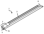
- FIGS. 1 is a perspective view of the insert 1.
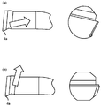
- FIG. 2 is a top view of the insert 1.
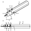
- FIG. FIG. 3 is a front view of another embodiment, FIG. 3 is a perspective view of a cutting tool in which the insert 1 of FIG. 1 is mounted on a holder, and FIG.
- the insert 1 has a rod shape with a substantially circular cross section, and is formed at a shank portion 2 and an end portion following the shank portion 2 to form a cutting blade portion 3.
- the corner 4a on the outer peripheral side of the cutting edge ridge line 4 protrudes toward the outer peripheral side of the rod-shaped body.
- the holder 20 is provided with a long insertion hole 21 into which the insert 1 is inserted from the distal end of the long holder 20, and the insertion hole 21 has an inclined surface of the insert 1. 8 is provided.
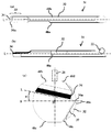
- FIG. 4 is a diagram for explaining the flow of chips when the work material is cut.
- the radial rake angle ⁇ of the cutting edge ridge line 4 is zero in the configuration of (a) in which the cutting edge ridge line 4 has a negative radial rake angle ⁇ by the configuration of FIGS.
- tip turns into chip
- the radial rake angle ⁇ is a reference plane S that is a straight line passing through the cutting point where the corner 4a of the cutting edge ridge line 4 contacts the workpiece and the circular center O of the machining section (machining locus), and the insert 1 refers to an angle formed by the cutting edge ridge line 4 (straight line L parallel to the cutting edge ridge line 4 in FIG. 2C) in the front end view.
- a desirable range of the negative radial rake angle ⁇ is 5 ° to 20 ° in consideration of chip disposal and cutting resistance.
- the negative radial rake angle ⁇ is 5 ° or more, the chip disposal is better, and if the negative radial rake angle ⁇ is 20 ° or less, the rake angle in the corner 4a is not too negative and the corner The cutting resistance in 4a is not so high.
- the processing locus becomes a circle indicated by a dotted line in FIG. 1C, and the corner 4 a protruding to the outer peripheral side of the cutting edge ridge line 4 is directly beside the processing locus. It is set to be at the same height as the center of the circle of the machining locus. Therefore, in the front end view of the insert 1, the cutting edge ridge line 4 is present above the half of the circular cross section of the insert 1, in other words, is present above the center of the insert. As a result, the rigidity of the cutting edge portion 3 of the insert 1 is improved, the bending during cutting can be reduced, and chattering of the insert 1 can be suppressed.
- a first taper (first cut surface) 6 is formed at an upper portion on the corner 4 a side that protrudes to the outer peripheral side of the cutting edge ridge line 4, in other words, at a position above the cutting edge ridge line 4. It is desirable that At this time, by forming the first taper 6 long to the rear of the rod-shaped insert 1, the protruding length of the insert 1 can be freely changed.
- the 2nd taper (lateral relief surface) 7 is formed in the lower part by the side of the corner 4a of the cutting edge ridgeline 4 in the front end view of the insert 1, and there is no taper other than a 2nd taper. That is, conventionally, as shown in FIG. 7, it was necessary to form a lower cut surface 30 in addition to the second taper 7, but according to the configuration of FIGS. Interference with the work material can be suppressed, and the cut surface 30 in the cutting edge portion 3 becomes unnecessary. For this reason, the number of processing steps for the lower cut surface 30 is reduced, resulting in cost reduction. 1 and 2, the second taper 7 extends to the rear shank portion 2.
- the inclined surface 8 is formed at the end opposite to the end where the cutting edge 3 is formed.
- the insert 1 is inserted into the insertion hole 21 of the holder 20 from the inclined surface 8 side, and is fixed by contact with the positioning member 22 provided on the holder 20 so that the inclined surface 8 comes into contact with the line. .
- the position of the cutting blade of the insert 1 in the longitudinal direction and the rotational direction is easy and the accuracy is increased.
- a plurality of positioning member mounting holes 23 for inserting the rod-shaped positioning member 22 are provided on the side surface of the holder 20.
- a rod-shaped positioning member 22 is inserted into one of the positioning member mounting holes 23 among the positioning member mounting holes 23.
- the reason why a large number of positioning member mounting holes 23 are provided is that the amount of protrusion of the insert 1 can be adjusted as appropriate.
- the positioning member 22 only needs to be in contact with the inclined surface 8 of the insert 1 such as a pin or a screw material.
- it has a rod shape and may be any shape such as a cylindrical column, a polygonal column such as a triangular column, etc., and is not particularly limited.
- a pin is used as the positioning member 22.
- the positioning member 22 is provided so that the axis of the positioning member 22 is perpendicular to the longitudinal direction of the insertion hole 21.
- the positioning member 22 is fixed by a method in which both ends of the cylindrical pin are clamped and fixed, or a screw in which one side end portion of the cylindrical pin is threaded and the threaded portion is provided in the holder 20.
- a method of tightening and fixing the screw member from the side surface of the cylindrical pin In FIG.
- a cylindrical pin (positioning member 22) is inserted from a positioning member mounting hole 23 present on the side surface of the holder 20, and a screw hole 26 is formed on the upper surface of the holder 20, and a screw member 27 is formed on the hole.
- a method is adopted in which the screw is fastened and brought into contact with the positioning member 22 and fixed.
- the position of the positioning member 22 in the insertion hole may be adjusted as appropriate according to the insertion angle of the inclined surface 8 of the insert 1.
- the inclined surface 8 of the insert 1 and the positioning member 22 are brought into contact with each other so as to be in line contact.
- the positioning member 22 is a cylindrical pin
- the insert 1 is mounted on the holder 20
- the direction perpendicular to the longitudinal direction of the inclined surface 8 and the length of the holder 20 on the outer peripheral surface of the positioning member 22 are set. It is comprised so that the direction perpendicular
- the outer periphery of the holder 20 is closer to the tip (first end) side of the holder 20 than the positioning member 22.
- a screw hole 24 penetrating from the surface to the insertion hole 21 is formed, a screw member 25 is screwed into the screw hole 24, and the outer peripheral surface of the shank portion 2 of the insert 1 is pressed and fixed at the tip of the screw member 25.
- the outer peripheral surface of the shank portion 2 that is in contact with the screw member 25 may be a curved surface.
- the insert 1 is not rotated and attached due to the influence of manufacturing variations, and the attachment position accuracy is high.
- the outer peripheral surface of the shank portion 2 that is in contact with the screw member 25 is a flat surface, if the clearance of the screw member 25 screwed into the holder is 10 to 30 ′, the front end plane of the screw member 25 Is abutted and fixed so as to contact the outer peripheral plane of the shank portion. The restraining force of the screw member 25 is higher in the fixed state where the surface comes into contact.
- the present invention is not limited to this, and for example, the configuration of the present invention shown in FIG.
- the front view in the other embodiment of the cutting tool in the front view of the insert 1, the side opposite to the corner 4 a protruding to the outer peripheral side of the cutting edge ridge line 4 following the first taper 6, in other words, An upper plane (second cut surface) 10 may be formed on the opposite side of the cutting edge ridge line 4 following the first taper 6, and the screw member 25 may be brought into contact with the upper plane 10 to be positioned and fixed.
- the lower plane 11 may be formed on the opposite side of the upper plane 10 of the insert 1, but the lower plane 11 may not be formed.
- the second taper 7 extends to the rear shank portion 2, but the present invention is not limited to this, and the configurations of FIGS. 5 and 6 can also be applied. is there. That is, in the insert 31 shown in FIGS. 5 and 6, the second taper 37 of the cutting edge portion 33 does not extend to the rear shank portion 32, and the shank portion 32 is cut when viewed from the front end side of the insert 31. With respect to the blade portion 33 (with respect to the second taper 37 in FIG. 6), it protrudes toward the one end 34 a side of the cutting edge ridge line 34. In the configuration of FIG.
- the shank portion 32 has a curve extending from the point 40 b to the point 40 c and a curve extending from the point 40 d including the point 40 a to the point 40 e with respect to the insertion hole 21 of the holder 20.
- the fixed portion has at least three fixed portions surrounding the center P of the insertion hole 21 and is fixed.
Landscapes
- Engineering & Computer Science (AREA)
- Mechanical Engineering (AREA)
- Cutting Tools, Boring Holders, And Turrets (AREA)
- Milling Processes (AREA)
Abstract
Priority Applications (4)
| Application Number | Priority Date | Filing Date | Title |
|---|---|---|---|
| EP12746480.8A EP2676751B1 (fr) | 2011-02-15 | 2012-02-15 | Outil de coupe |
| US13/985,846 US9764389B2 (en) | 2011-02-15 | 2012-02-15 | Cutting tool |
| CN201280004705.XA CN103298576B (zh) | 2011-02-15 | 2012-02-15 | 切削工具 |
| JP2012557995A JP5701321B2 (ja) | 2011-02-15 | 2012-02-15 | 切削工具 |
Applications Claiming Priority (2)
| Application Number | Priority Date | Filing Date | Title |
|---|---|---|---|
| JP2011-029822 | 2011-02-15 | ||
| JP2011029822 | 2011-02-15 |
Publications (1)
| Publication Number | Publication Date |
|---|---|
| WO2012111710A1 true WO2012111710A1 (fr) | 2012-08-23 |
Family
ID=46672623
Family Applications (1)
| Application Number | Title | Priority Date | Filing Date |
|---|---|---|---|
| PCT/JP2012/053541 WO2012111710A1 (fr) | 2011-02-15 | 2012-02-15 | Outil de coupe |
Country Status (5)
| Country | Link |
|---|---|
| US (1) | US9764389B2 (fr) |
| EP (1) | EP2676751B1 (fr) |
| JP (1) | JP5701321B2 (fr) |
| CN (1) | CN103298576B (fr) |
| WO (1) | WO2012111710A1 (fr) |
Cited By (2)
| Publication number | Priority date | Publication date | Assignee | Title |
|---|---|---|---|---|
| EP2821168A1 (fr) * | 2013-07-04 | 2015-01-07 | Applitec Moutier S.A. | Système d'usinage intérieur |
| US11161179B2 (en) * | 2017-04-12 | 2021-11-02 | Stojan Stojanovski | Cutting tool assembly |
Families Citing this family (4)
| Publication number | Priority date | Publication date | Assignee | Title |
|---|---|---|---|---|
| CN104816001B (zh) * | 2015-04-17 | 2017-06-16 | 郑锡添 | 小孔塑料件镗刀 |
| DE102015112049B3 (de) * | 2015-07-23 | 2016-09-22 | Stoba Sondermaschinen Gmbh | Spannzangensystem mit Positionierung |
| AT522997B1 (de) * | 2019-10-09 | 2021-11-15 | Diametal A G | Drehwerkzeug mit Werkzeugwechsler |
| USD956222S1 (en) | 2020-08-21 | 2022-06-28 | Stryker European Operations Limited | Surgical bur assembly |
Citations (3)
| Publication number | Priority date | Publication date | Assignee | Title |
|---|---|---|---|---|
| JP2000271805A (ja) | 1999-03-19 | 2000-10-03 | Mitsubishi Materials Corp | 穴加工工具 |
| WO2008053633A1 (fr) * | 2006-10-31 | 2008-05-08 | Kyocera Corporation | Garniture de coupe |
| JP2009034819A (ja) * | 2008-11-17 | 2009-02-19 | Kyocera Corp | 切削工具 |
Family Cites Families (13)
| Publication number | Priority date | Publication date | Assignee | Title |
|---|---|---|---|---|
| BE637666A (fr) * | 1962-09-27 | |||
| SE419834B (sv) * | 1977-02-11 | 1981-08-31 | Seco Tools Ab | Vendsker och verktyg for hornfresning |
| DE2713529A1 (de) * | 1977-03-26 | 1978-09-28 | Ewald Granacher | Schneidwerkzeug, insbesondere ausdrehmeissel fuer dreh-, bohr- oder aehnliche maschinen |
| JPS62117003U (fr) | 1986-01-13 | 1987-07-25 | ||
| US5332339A (en) * | 1991-06-19 | 1994-07-26 | Mitsubishi Materials Corporation | Throw-away cutting tool |
| US5848862A (en) * | 1997-06-24 | 1998-12-15 | Antoun; Gregory S. | Boring bar with reverse mounted insert |
| JP2004216495A (ja) * | 2003-01-14 | 2004-08-05 | Mitsubishi Materials Corp | 工具ホルダ |
| DE102004053511B4 (de) * | 2003-10-30 | 2011-06-09 | Kyocera Corporation | Schneidwerkzeug |
| IL159188A (en) * | 2003-12-04 | 2008-08-07 | Uzi Gati | Cutting placement for diligent operations |
| DE112008002261B4 (de) * | 2007-08-31 | 2015-06-25 | Kyocera Corporation | Schneideinsatz, Schneidwerkzeug und Schneidverfahren |
| US8516935B2 (en) * | 2008-06-27 | 2013-08-27 | Kyocera Corporation | Cutting tool and cutting method using the same |
| WO2011001873A1 (fr) * | 2009-06-29 | 2011-01-06 | 京セラ株式会社 | Insert, support, et outil de coupe utilisant ledit insert et ledit support |
| CN101912987B (zh) | 2010-08-31 | 2012-01-18 | 株洲钻石切削刀具股份有限公司 | 用于大长径比深孔加工的钻头 |
-
2012
- 2012-02-15 WO PCT/JP2012/053541 patent/WO2012111710A1/fr active Application Filing
- 2012-02-15 EP EP12746480.8A patent/EP2676751B1/fr active Active
- 2012-02-15 US US13/985,846 patent/US9764389B2/en active Active
- 2012-02-15 CN CN201280004705.XA patent/CN103298576B/zh active Active
- 2012-02-15 JP JP2012557995A patent/JP5701321B2/ja active Active
Patent Citations (3)
| Publication number | Priority date | Publication date | Assignee | Title |
|---|---|---|---|---|
| JP2000271805A (ja) | 1999-03-19 | 2000-10-03 | Mitsubishi Materials Corp | 穴加工工具 |
| WO2008053633A1 (fr) * | 2006-10-31 | 2008-05-08 | Kyocera Corporation | Garniture de coupe |
| JP2009034819A (ja) * | 2008-11-17 | 2009-02-19 | Kyocera Corp | 切削工具 |
Non-Patent Citations (1)
| Title |
|---|
| See also references of EP2676751A4 |
Cited By (3)
| Publication number | Priority date | Publication date | Assignee | Title |
|---|---|---|---|---|
| EP2821168A1 (fr) * | 2013-07-04 | 2015-01-07 | Applitec Moutier S.A. | Système d'usinage intérieur |
| WO2015000985A1 (fr) * | 2013-07-04 | 2015-01-08 | Applitec Moutier Sa | Systeme d'usinage |
| US11161179B2 (en) * | 2017-04-12 | 2021-11-02 | Stojan Stojanovski | Cutting tool assembly |
Also Published As
| Publication number | Publication date |
|---|---|
| CN103298576A (zh) | 2013-09-11 |
| CN103298576B (zh) | 2015-10-14 |
| US20140161549A1 (en) | 2014-06-12 |
| EP2676751A4 (fr) | 2014-12-17 |
| EP2676751B1 (fr) | 2016-08-10 |
| EP2676751A1 (fr) | 2013-12-25 |
| JP5701321B2 (ja) | 2015-04-15 |
| JPWO2012111710A1 (ja) | 2014-07-07 |
| US9764389B2 (en) | 2017-09-19 |
Similar Documents
| Publication | Publication Date | Title |
|---|---|---|
| JP5701321B2 (ja) | 切削工具 | |
| JP4712124B2 (ja) | インサート及びホルダ並びにそれらを用いる切削工具 | |
| EP1526293B1 (fr) | Couple de pièces filetées | |
| JP4360620B2 (ja) | 切削工具用ホルダおよびそれを用いた切削工具 | |
| JP5781163B2 (ja) | ホルダおよび切削工具 | |
| JP2018140482A (ja) | ポリゴン加工用工具 | |
| JP4431164B2 (ja) | 内径加工用工具 | |
| JP4815366B2 (ja) | 切削用のインサート及びホルダー並びに切削工具 | |
| JP2013071214A (ja) | 切削工具 | |
| JP2008213077A (ja) | 切削インサート及びインサート着脱式切削工具 | |
| WO2020230569A1 (fr) | Support de perçage et outil de tournage | |
| KR20190015559A (ko) | 선단 교환식 절삭 공구의 본체부 및 선단 교환식 절삭 공구 | |
| JP5882822B2 (ja) | 固定部材および切削工具 | |
| JP5693142B2 (ja) | 切削工具 | |
| JP4262049B2 (ja) | 切削工具 | |
| JP2012111006A (ja) | 切削工具 | |
| JP2012024875A (ja) | インサートおよび切削工具 | |
| JP6726410B2 (ja) | 切削インサート及び回転切削工具 | |
| JP2014034066A (ja) | インサートおよび切削工具 | |
| JP4395397B2 (ja) | スローアウェイチップおよびそれを用いた切削工具 | |
| JP2004074322A (ja) | スローアウェイチップおよびそれを用いた切削工具 | |
| JP2008290214A (ja) | 中ぐり加工用チップおよびこれを用いた中ぐり工具 | |
| JP2005186201A (ja) | スローアウェイチップおよびそれを用いた切削工具 | |
| JP2009034819A (ja) | 切削工具 | |
| JP2006192530A (ja) | スローアウェイ式切削工具及びスローアウェイチップ |
Legal Events
| Date | Code | Title | Description |
|---|---|---|---|
| 121 | Ep: the epo has been informed by wipo that ep was designated in this application |
Ref document number: 12746480 Country of ref document: EP Kind code of ref document: A1 |
|
| ENP | Entry into the national phase |
Ref document number: 2012557995 Country of ref document: JP Kind code of ref document: A |
|
| NENP | Non-entry into the national phase |
Ref country code: DE |
|
| REEP | Request for entry into the european phase |
Ref document number: 2012746480 Country of ref document: EP |
|
| WWE | Wipo information: entry into national phase |
Ref document number: 2012746480 Country of ref document: EP |
|
| WWE | Wipo information: entry into national phase |
Ref document number: 13985846 Country of ref document: US |