WO2012111600A1 - Cosse de raccordement - Google Patents
Cosse de raccordement Download PDFInfo
- Publication number
- WO2012111600A1 WO2012111600A1 PCT/JP2012/053247 JP2012053247W WO2012111600A1 WO 2012111600 A1 WO2012111600 A1 WO 2012111600A1 JP 2012053247 W JP2012053247 W JP 2012053247W WO 2012111600 A1 WO2012111600 A1 WO 2012111600A1
- Authority
- WO
- WIPO (PCT)
- Prior art keywords
- female terminal
- terminal fitting
- lance
- housing
- fitting
- Prior art date
Links
Images


Classifications
-
- H—ELECTRICITY
- H01—ELECTRIC ELEMENTS
- H01R—ELECTRICALLY-CONDUCTIVE CONNECTIONS; STRUCTURAL ASSOCIATIONS OF A PLURALITY OF MUTUALLY-INSULATED ELECTRICAL CONNECTING ELEMENTS; COUPLING DEVICES; CURRENT COLLECTORS
- H01R13/00—Details of coupling devices of the kinds covered by groups H01R12/70 or H01R24/00 - H01R33/00
- H01R13/62—Means for facilitating engagement or disengagement of coupling parts or for holding them in engagement
- H01R13/627—Snap or like fastening
-
- H—ELECTRICITY
- H01—ELECTRIC ELEMENTS
- H01R—ELECTRICALLY-CONDUCTIVE CONNECTIONS; STRUCTURAL ASSOCIATIONS OF A PLURALITY OF MUTUALLY-INSULATED ELECTRICAL CONNECTING ELEMENTS; COUPLING DEVICES; CURRENT COLLECTORS
- H01R13/00—Details of coupling devices of the kinds covered by groups H01R12/70 or H01R24/00 - H01R33/00
- H01R13/40—Securing contact members in or to a base or case; Insulating of contact members
- H01R13/42—Securing in a demountable manner
- H01R13/422—Securing in resilient one-piece base or case, e.g. by friction; One-piece base or case formed with resilient locking means
- H01R13/4223—Securing in resilient one-piece base or case, e.g. by friction; One-piece base or case formed with resilient locking means comprising integral flexible contact retaining fingers
-
- H—ELECTRICITY
- H01—ELECTRIC ELEMENTS
- H01R—ELECTRICALLY-CONDUCTIVE CONNECTIONS; STRUCTURAL ASSOCIATIONS OF A PLURALITY OF MUTUALLY-INSULATED ELECTRICAL CONNECTING ELEMENTS; COUPLING DEVICES; CURRENT COLLECTORS
- H01R31/00—Coupling parts supported only by co-operation with counterpart
- H01R31/08—Short-circuiting members for bridging contacts in a counterpart
Definitions
- the present invention relates to a joint connector used when connecting a plurality of electric wires to each other or distributing one system of electric wires to a plurality of wires.
- FIG. 5 shows a conventional example of a joint connector.
- the joint connector 100 is disclosed in the following Patent Document 1, and includes a joint terminal (bus bar) 110, a plurality of female terminal fittings 120, a first connector housing 130, and a second connector housing 140. It is equipped with.
- the joint terminal 110 is a press-formed product of a metal plate, and includes a plurality of tab pieces 111 for fitting and connecting the female terminal fitting 120, and a connecting portion 112 that electrically connects the tab pieces 111.
- the female terminal fitting 120 is a press-molded product of a metal plate, and a rectangular tube-shaped box part 121 into which the tab piece 111 is fitted, and a wire crimping that crimps the electric wire 150 extending from the rear end of the box part 121.
- the first connector housing 130 is a resin injection-molded product and includes a housing one end 131 and a cylindrical hood 132 extending from the housing one end 131.
- the housing one end 131 accommodates and holds the joint terminal 110 with the tab piece 111 facing the other end 130a (right end in FIG. 5) of the housing.
- the housing one end 131 holds the joint terminal 110 by insert molding, for example.
- the hood portion 132 is a cylindrical portion into which the second connector housing 140 is fitted.
- the hood portion 132 is provided with a lock hole portion 134 for fixing the fitted second connector housing 140.
- the second connector housing 140 accommodates and holds the female terminal fitting 120 and is fitted and connected to the first connector housing 130.
- the second connector housing 140 includes a plurality of female terminal accommodating holes 141 that accommodate the female terminal fittings 120, a lance 142 that prevents the female terminal fittings 120 inserted into the female terminal accommodating holes 141, and a first connector housing 140. And a lock protrusion 143 that locks the coupled state with the connector housing 130.
- the lance 142 is provided with a terminal locking protrusion 142b protruding toward the female terminal accommodation hole 141 on the free end side of the elastic piece 142a extending along the female terminal accommodation hole 141.
- the lance 142 has the terminal locking projection 142b formed by interference between the box portion 121 of the female terminal fitting 120 and the terminal locking projection 142b.
- the elastic piece 142a is bent and deformed so as to retreat to the outside of the female terminal accommodating hole 141, and the insertion of the female terminal fitting 120 is allowed.
- the terminal locking projection 142b When the female terminal fitting 120 is inserted to the specified position, the terminal locking projection 142b is engaged with the engagement recess 123 of the female terminal fitting 120 by the elastic restoring force of the terminal locking projection 142b, so that the female type The terminal fitting 120 is prevented from coming off.
- the lock protrusion 143 engages with the lock hole 134 of the first connector housing 130 so that the connector housings Lock the combined state.
- a half-fitting detection protrusion 135 is provided at one end 131 of the first connector housing 130.
- This half-fitting detection projection 135 is a projection that is inserted into the retreat space 145 of the lance 142 when the first connector housing 130 and the second connector housing 140 are fitted together.
- the female terminal fitting 120 is in a semi-fitted state in which the female terminal fitting 120 is not completely fitted into the female terminal receiving hole 141, the lance 142 is deflected and displaced toward the retracting space 145.
- the half-fitting detection protrusion 135 interferes with the tip of the lance 142 that is displaced to the retreat space 145, and the mutual fitting of the housings is hindered. Thereby, it is detected that the female terminal fitting 120 is in a half-fitted state.
- the above-mentioned joint connector 100 has a problem that the number of parts is large and the cost is high because the first connector housing 130 and the second connector housing 140 need to be prepared separately. Therefore, in order to reduce costs, the inventor of the present application examined a joint connector in which the joint terminal and the female terminal fitting are accommodated together in one housing and the existing one is used as the female terminal fitting. I tried.
- the existing female terminal fitting to be diverted in this case has a primary locking projection (front projection) on the front side and a projection (rear projection) as a stabilizer on the rear side. It has been newly found that the following problems may occur when this female terminal fitting is used.
- an object of the present invention is to provide a joint connector which is intended to solve the above-described problems and prevents erroneous locking in the middle insertion state of the female terminal fitting.
- the above object of the present invention can be achieved by the following constitution. (1) a plurality of female terminal fittings; A joint terminal comprising a plurality of tab pieces for fitting and connecting the female terminal metal fittings, and a connecting portion that conductively connects these tab pieces; One end of the housing that accommodates and holds the joint terminal with the tab piece facing the other end of the housing, and the female terminal fitting and the tab piece are fitted by inserting the female terminal fitting to a specified position.
- a resin connector housing having a lance for retaining the female terminal fitting inserted in a specified position, and The side portion of the female terminal fitting along the insertion direction of the female terminal fitting protrudes in the same direction intersecting the insertion direction of the female terminal fitting and before and after the insertion direction of the female terminal fitting.
- a front protrusion and a rear protrusion which are separated from each other and independent of each other in the left-right direction, are provided,
- the lance includes a locking wall that prevents the female terminal fitting from coming off by engaging with the rear projection when the rear projection passes, and the front projection when the front projection passes through the lance.
- a joint connector provided with a rib that prevents the locking wall and the front protrusion from engaging with each other.
- the joint connector having the above configuration (1), when the front protrusion passes through the lance, the rib prevents the front protrusion from engaging with the locking wall. Only when the rear projection has been inserted through the lance, the locking wall of the lance can be engaged with the rear projection. Accordingly, it is possible to prevent erroneous locking in the middle insertion state of the female terminal fitting, and to reduce the possibility of misidentifying that the insertion of the terminal is completed despite being in the middle insertion state. .
- the terminal holding force increases.
- the present invention it is possible to prevent erroneous locking in the midway insertion state of the female terminal fitting, and erroneously recognize that the insertion of the female terminal fitting has been completed despite being in the midway insertion state.
- the fear can be reduced.
- FIG. 1 is an exploded perspective view of an embodiment of a joint connector device according to the present invention.
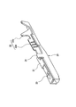
- FIG. 2 is a perspective view of the female terminal fitting shown in FIG.
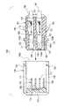
- FIG. 3 is a partially broken perspective view showing the internal structure of the housing of the joint connector shown in FIG. 4 (a) and 4 (b) are operation explanatory views when the female terminal fitting is inserted into the housing of the joint connector shown in FIG. 1, and
- FIG. 4B is a longitudinal sectional view showing a state where the insertion is completed.
- FIG. 5 is a longitudinal sectional view of a conventional joint connector in an exploded state.
- FIG. 1 is an exploded perspective view of an embodiment of a joint connector according to the present invention
- FIG. 2 is a perspective view of the female terminal fitting shown in FIG. 1 viewed obliquely from the front end side
- FIG. 3 is a joint shown in FIG.
- FIG. 4 (a) and FIG. 4 (b) are operation explanatory views when a female terminal fitting is inserted into the joint connector housing shown in FIG.
- FIG. 4A is a side cross-sectional view showing a state of being inserted halfway
- FIG. 4B is a side cross-sectional view showing a state of being completely inserted.
- the joint connector 1 includes a joint terminal 10, a female terminal fitting 20, and a resin connector housing 30.
- the joint terminal 10 is a press-molded product of a metal plate, and includes a plurality of tab pieces 11 for fitting and connecting the female terminal fitting 20 and a connecting portion 12 that electrically connects these tab pieces 11.
- the female terminal fitting 20 is a press-formed product of a metal plate, and extends from a rectangular tube-shaped box portion 21 into which the tab piece 11 is fitted and a rear end of the box portion 21 as shown in FIGS. 1 and 2.
- An electric wire caulking portion 22 for taking out and crimping an electric wire and an insertion guide protrusion 24 (a rear protrusion described later) are provided.
- the electric wire crimping portion 22 includes a conductor crimping piece 22a for crimping the conductor of the electric wire and a covering crimping piece 22b for fixing the electric wire by crimping the electric wire covering portion.
- the female terminal fitting 20 Since the female terminal fitting 20 is a diversion of other connector terminals, the female terminal fitting 20 is inserted in the insertion direction of the female terminal fitting 20 on the side portion along the insertion direction of the female terminal fitting 20 into the female terminal receiving hole 34.
- a primary locking projection (hereinafter referred to as a front projection) 23 that protrudes in the same crossing direction and is spaced apart from each other in the insertion direction of the female terminal fitting 20 to be independent of each other and displaced from each other in the left-right direction, and an insertion guide And a projecting piece 24 (hereinafter referred to as a rear projection).
- the rear projection 24 is a tongue-like piece extending along the insertion direction into the female terminal receiving hole 34 of the connector housing 30 described later at a position near the rear end of the box portion 21.
- the rear protrusion 24 is formed in a tongue shape by extending a part of the side wall of the box portion 21 and bending it.
- the connector housing 30 is a resin injection-molded product, and includes a housing one end portion 31 and a housing other end portion 32 that is an end portion opposite to the housing one end portion 31.
- the housing one end 31 accommodates and holds the joint terminal 10 with the tab piece 11 facing the housing other end 32 side.
- a plurality of female terminal accommodation holes 34 are arranged in the housing other end portion 32.
- the plurality of female terminal receiving holes 34 are holes that bring the female terminal fitting 20 and the tab piece 11 into a fitted state by inserting the female terminal fitting 20 to a specified position.
- the specified position is a position at which the tab piece 11 and the box portion 21 obtain a contact length necessary and sufficient for electrical connection.
- the female terminal accommodating hole 34 is provided with a guide groove 35 as shown in FIG.
- the guide groove 35 guides the female terminal fitting 20 to a specified position by slidably guiding the rear protrusion 24 when the female terminal fitting 20 is inserted into the female terminal receiving hole 34.
- the lance 36 includes an elastic piece 36 a extending along the female terminal accommodating hole 34, and the elastic piece 36 a (see FIGS. 4A and 4B). Terminal locking projections 36b projecting from the right end in FIG. 4 (b).
- the terminal locking protrusion 36b protrudes toward the female terminal accommodating hole 34, and as shown in FIG. 4B, the terminal locking protrusion 36b engages with the rear protrusion 24 inserted at a specified position, thereby 20 is retained.
- the female terminal fitting 20 is inserted into the female terminal receiving hole 34 of the connector housing 30, and when the rear projection 24 passes through the lance 36, it engages with the rear projection 24.
- a locking wall 36c for preventing the female terminal fitting 20 from coming off is provided.
- the locking wall 36c is provided with a rib 15 that prevents the locking wall 36c and the front protrusion 23 from engaging when the front protrusion 23 passes through the lance 36.
- the rib 15 is provided at a horizontal position where the rib 15 interferes with the front protrusion 23, but is provided at a horizontal position where the rib 15 does not interfere with the rear protrusion 24.
- One end of the rib 15 is fixed to the lance 36.
- the other end of the rib 15 may be a free end without being fixed anywhere, but is fixed to the connector housing 30 in this embodiment.
- the lance 36 has a double-sided support structure, and the terminal holding force by the lance 36 increases.
- the joint terminal 10 is attached to the front portion (housing one end portion 31) of the connector housing 30.
- the female terminal fitting 20 is inserted into each female terminal receiving hole 34 from the rear of the connector housing 30.
- the rib 15 interferes with the front projection 23 and the lance 36 bends outward so that the front projection 23 is locked. Engagement with the wall 36c can be prevented, and the front protrusion 23 can pass through the lance 36 as it is.
- the rib 15 is in a position where it does not interfere with the rear projection 24.
- the rear protrusion 24 can be engaged with the locking wall 36c of the lance 36 that has returned from the bending as it passes, and the female terminal fitting 20 can be prevented from coming off and fixed for the first time at this stage.
- the present invention it is possible to prevent erroneous locking in the midway insertion state of the female terminal fitting, and erroneously recognize that the insertion of the female terminal fitting has been completed despite being in the midway insertion state.
- the fear can be reduced.
Landscapes
- Connector Housings Or Holding Contact Members (AREA)
- Details Of Connecting Devices For Male And Female Coupling (AREA)
Abstract
Sur la partie latérale d'une ferrure de terminal femelle (20) et suivant une direction d'insertion, sont agencées une saillie côté avant (23) et une saillie côté arrière (24) qui sont proéminentes dans une même direction croisant la direction d'insertion de la ferrure de terminal femelle (20), qui sont indépendantes l'une de l'autre du fait d'un écart avant-arrière dans la direction d'insertion de la ferrure de terminal femelle (20), et qui présentes des positions décalées l'une de l'autre dans la direction latérale. Au niveau d'une lance (36) sont agencées : une paroi de mise en prise (36c) qui retient une borne par engagement de la saillie côté arrière (24) quand il y a dépassement par cette dernière; et une nervure (15) empêchant l'engagement de la paroi de mise en prise (36c) avec la saillie côté avant (23) quand il y a dépassement de la lance (36) par la saillie côté avant (23).
Priority Applications (3)
| Application Number | Priority Date | Filing Date | Title |
|---|---|---|---|
| DE112012000844T DE112012000844T5 (de) | 2011-02-15 | 2012-02-13 | Steckverbinder |
| CN2012800090280A CN103392270A (zh) | 2011-02-15 | 2012-02-13 | 接合连接器 |
| US13/967,480 US20130330956A1 (en) | 2011-02-15 | 2013-08-15 | Joint Connector |
Applications Claiming Priority (2)
| Application Number | Priority Date | Filing Date | Title |
|---|---|---|---|
| JP2011-030100 | 2011-02-15 | ||
| JP2011030100A JP2012169186A (ja) | 2011-02-15 | 2011-02-15 | ジョイントコネクタ |
Related Child Applications (1)
| Application Number | Title | Priority Date | Filing Date |
|---|---|---|---|
| US13/967,480 Continuation US20130330956A1 (en) | 2011-02-15 | 2013-08-15 | Joint Connector |
Publications (1)
| Publication Number | Publication Date |
|---|---|
| WO2012111600A1 true WO2012111600A1 (fr) | 2012-08-23 |
Family
ID=46672519
Family Applications (1)
| Application Number | Title | Priority Date | Filing Date |
|---|---|---|---|
| PCT/JP2012/053247 WO2012111600A1 (fr) | 2011-02-15 | 2012-02-13 | Cosse de raccordement |
Country Status (5)
| Country | Link |
|---|---|
| US (1) | US20130330956A1 (fr) |
| JP (1) | JP2012169186A (fr) |
| CN (1) | CN103392270A (fr) |
| DE (1) | DE112012000844T5 (fr) |
| WO (1) | WO2012111600A1 (fr) |
Cited By (1)
| Publication number | Priority date | Publication date | Assignee | Title |
|---|---|---|---|---|
| JP2019046794A (ja) * | 2017-08-30 | 2019-03-22 | モレックス エルエルシー | コネクタ |
Families Citing this family (8)
| Publication number | Priority date | Publication date | Assignee | Title |
|---|---|---|---|---|
| GB201204866D0 (en) * | 2012-03-20 | 2012-05-02 | Trw Ltd | Fork type electrical connector |
| JP6141612B2 (ja) * | 2012-09-21 | 2017-06-07 | 矢崎総業株式会社 | コネクタ |
| DE102014202316B4 (de) * | 2014-02-07 | 2021-04-01 | Te Connectivity Germany Gmbh | Kontaktträger mit einem Grundkörper und wenigstens einem Kontaktelement, Werkzeug zum Spritzgießen eines Kontaktträgers und Verfahren zur Herstellung eines Kontaktträgers |
| JP6440978B2 (ja) * | 2014-07-07 | 2018-12-19 | 矢崎総業株式会社 | コネクタ |
| JP6206392B2 (ja) * | 2014-12-25 | 2017-10-04 | 株式会社オートネットワーク技術研究所 | ジョイントコネクタ |
| KR101755856B1 (ko) * | 2015-10-06 | 2017-07-19 | 현대자동차주식회사 | 차량용 다중 접지 커넥터 |
| DE102016104828A1 (de) * | 2016-03-16 | 2017-09-21 | Te Connectivity Germany Gmbh | Elektrische Kontaktvorrichtung, elektrische Kontakteinrichtung sowie elektrischer Verbinder |
| JP7281089B2 (ja) * | 2019-11-29 | 2023-05-25 | 住友電装株式会社 | コネクタ |
Citations (4)
| Publication number | Priority date | Publication date | Assignee | Title |
|---|---|---|---|---|
| JP2009016292A (ja) * | 2007-07-09 | 2009-01-22 | Auto Network Gijutsu Kenkyusho:Kk | ジョイントコネクタ |
| WO2009078374A1 (fr) * | 2007-12-18 | 2009-06-25 | Autonetworks Technologies, Ltd. | Connecteur de raccordement et procédé de court-circuitage de fil l'utilisant |
| WO2009090942A1 (fr) * | 2008-01-17 | 2009-07-23 | Autonetworks Technologies, Ltd. | Faisceau de fils et procédé d'assemblage de faisceau de fils |
| JP2010067483A (ja) * | 2008-09-11 | 2010-03-25 | Sumitomo Wiring Syst Ltd | ジョイントコネクタおよびジョイントコネクタ付きワイヤハーネス |
Family Cites Families (4)
| Publication number | Priority date | Publication date | Assignee | Title |
|---|---|---|---|---|
| JPH08250185A (ja) | 1995-01-13 | 1996-09-27 | Sumitomo Wiring Syst Ltd | ジョイントコネクタ及びジョイントコネクタ用キャップ |
| US20060292928A1 (en) * | 2005-06-23 | 2006-12-28 | Morello John R | Electrical connector |
| JP4820270B2 (ja) * | 2005-11-22 | 2011-11-24 | 矢崎総業株式会社 | コネクタ |
| JP5240114B2 (ja) | 2009-07-28 | 2013-07-17 | 富士通株式会社 | 携帯機器 |
-
2011
- 2011-02-15 JP JP2011030100A patent/JP2012169186A/ja not_active Ceased
-
2012
- 2012-02-13 DE DE112012000844T patent/DE112012000844T5/de not_active Withdrawn
- 2012-02-13 CN CN2012800090280A patent/CN103392270A/zh active Pending
- 2012-02-13 WO PCT/JP2012/053247 patent/WO2012111600A1/fr active Application Filing
-
2013
- 2013-08-15 US US13/967,480 patent/US20130330956A1/en not_active Abandoned
Patent Citations (4)
| Publication number | Priority date | Publication date | Assignee | Title |
|---|---|---|---|---|
| JP2009016292A (ja) * | 2007-07-09 | 2009-01-22 | Auto Network Gijutsu Kenkyusho:Kk | ジョイントコネクタ |
| WO2009078374A1 (fr) * | 2007-12-18 | 2009-06-25 | Autonetworks Technologies, Ltd. | Connecteur de raccordement et procédé de court-circuitage de fil l'utilisant |
| WO2009090942A1 (fr) * | 2008-01-17 | 2009-07-23 | Autonetworks Technologies, Ltd. | Faisceau de fils et procédé d'assemblage de faisceau de fils |
| JP2010067483A (ja) * | 2008-09-11 | 2010-03-25 | Sumitomo Wiring Syst Ltd | ジョイントコネクタおよびジョイントコネクタ付きワイヤハーネス |
Cited By (1)
| Publication number | Priority date | Publication date | Assignee | Title |
|---|---|---|---|---|
| JP2019046794A (ja) * | 2017-08-30 | 2019-03-22 | モレックス エルエルシー | コネクタ |
Also Published As
| Publication number | Publication date |
|---|---|
| CN103392270A (zh) | 2013-11-13 |
| DE112012000844T5 (de) | 2013-11-14 |
| US20130330956A1 (en) | 2013-12-12 |
| JP2012169186A (ja) | 2012-09-06 |
Similar Documents
| Publication | Publication Date | Title |
|---|---|---|
| WO2012111600A1 (fr) | Cosse de raccordement | |
| KR101973894B1 (ko) | 단자 위치 확인 장치를 가진 전기 커넥터 | |
| US7347710B2 (en) | Electric wire connector having a lock securing mechanism | |
| US7985106B2 (en) | Female type terminal pin | |
| JP4963702B2 (ja) | 端子位置保証装置を有するコネクタ組立体 | |
| JP2017098222A (ja) | 端子位置保証装置を有する電気コネクタ | |
| TWI435500B (zh) | Joint connector and terminal half insert inspection method | |
| JP2016001579A (ja) | 導電端子 | |
| EP1601063A1 (fr) | Dispositif de raccordement | |
| JP2010056084A (ja) | 電気コネクタ用端子位置保証部材 | |
| JP2002319456A (ja) | シールドコネクタ | |
| WO2016208368A1 (fr) | Connecteur de raccordement | |
| US6129574A (en) | Connector having a construction for preventing an erroneous assembling of a connector housing and a cover | |
| TWI538320B (zh) | 具有結合檢知手段的連接器 | |
| JP2023055207A (ja) | 引抜抵抗を増加させるためのケーブル保護カバー | |
| JP2012174432A (ja) | ジョイントコネクタ | |
| WO2012111572A1 (fr) | Cosse, et fixation pour assemblage de cette cosse | |
| KR102591645B1 (ko) | 커넥터 어셈블리 | |
| WO2013176129A1 (fr) | Couvercle de protection de fil électrique | |
| JP7142088B2 (ja) | プラグコネクタ部品 | |
| JP5183315B2 (ja) | コネクタ | |
| US9196993B2 (en) | Connector unit | |
| WO2012111529A1 (fr) | Cosse de raccordement, et dispositif d'assemblage de cosse | |
| JP2008204720A (ja) | 短絡部材、短絡部材付電線、ジョイントコネクタおよび短絡方法 | |
| JP5195659B2 (ja) | コネクタ |
Legal Events
| Date | Code | Title | Description |
|---|---|---|---|
| 121 | Ep: the epo has been informed by wipo that ep was designated in this application |
Ref document number: 12747845 Country of ref document: EP Kind code of ref document: A1 |
|
| WWE | Wipo information: entry into national phase |
Ref document number: 1120120008448 Country of ref document: DE Ref document number: 112012000844 Country of ref document: DE |
|
| 122 | Ep: pct application non-entry in european phase |
Ref document number: 12747845 Country of ref document: EP Kind code of ref document: A1 |