WO2012111528A1 - ジョイントコネクタ装置 - Google Patents
ジョイントコネクタ装置 Download PDFInfo
- Publication number
- WO2012111528A1 WO2012111528A1 PCT/JP2012/053006 JP2012053006W WO2012111528A1 WO 2012111528 A1 WO2012111528 A1 WO 2012111528A1 JP 2012053006 W JP2012053006 W JP 2012053006W WO 2012111528 A1 WO2012111528 A1 WO 2012111528A1
- Authority
- WO
- WIPO (PCT)
- Prior art keywords
- female terminal
- terminal fitting
- lance
- fitting
- jig
- Prior art date
- Legal status (The legal status is an assumption and is not a legal conclusion. Google has not performed a legal analysis and makes no representation as to the accuracy of the status listed.)
- Ceased
Links
Images




Classifications
-
- H—ELECTRICITY
- H01—ELECTRIC ELEMENTS
- H01R—ELECTRICALLY-CONDUCTIVE CONNECTIONS; STRUCTURAL ASSOCIATIONS OF A PLURALITY OF MUTUALLY-INSULATED ELECTRICAL CONNECTING ELEMENTS; COUPLING DEVICES; CURRENT COLLECTORS
- H01R43/00—Apparatus or processes specially adapted for manufacturing, assembling, maintaining, or repairing of line connectors or current collectors or for joining electric conductors
- H01R43/20—Apparatus or processes specially adapted for manufacturing, assembling, maintaining, or repairing of line connectors or current collectors or for joining electric conductors for assembling or disassembling contact members with insulating base, case or sleeve
-
- H—ELECTRICITY
- H01—ELECTRIC ELEMENTS
- H01R—ELECTRICALLY-CONDUCTIVE CONNECTIONS; STRUCTURAL ASSOCIATIONS OF A PLURALITY OF MUTUALLY-INSULATED ELECTRICAL CONNECTING ELEMENTS; COUPLING DEVICES; CURRENT COLLECTORS
- H01R13/00—Details of coupling devices of the kinds covered by groups H01R12/70 or H01R24/00 - H01R33/00
- H01R13/40—Securing contact members in or to a base or case; Insulating of contact members
- H01R13/42—Securing in a demountable manner
- H01R13/422—Securing in resilient one-piece base or case, e.g. by friction; One-piece base or case formed with resilient locking means
- H01R13/4223—Securing in resilient one-piece base or case, e.g. by friction; One-piece base or case formed with resilient locking means comprising integral flexible contact retaining fingers
-
- Y—GENERAL TAGGING OF NEW TECHNOLOGICAL DEVELOPMENTS; GENERAL TAGGING OF CROSS-SECTIONAL TECHNOLOGIES SPANNING OVER SEVERAL SECTIONS OF THE IPC; TECHNICAL SUBJECTS COVERED BY FORMER USPC CROSS-REFERENCE ART COLLECTIONS [XRACs] AND DIGESTS
- Y10—TECHNICAL SUBJECTS COVERED BY FORMER USPC
- Y10T—TECHNICAL SUBJECTS COVERED BY FORMER US CLASSIFICATION
- Y10T29/00—Metal working
- Y10T29/53—Means to assemble or disassemble
- Y10T29/5313—Means to assemble electrical device
- Y10T29/532—Conductor
- Y10T29/53209—Terminal or connector
Definitions
- the present invention relates to a joint connector device in which a plurality of female terminal fittings are connected to each other by joint terminals.
- FIG. 8 shows a conventional example of a joint connector.
- the joint connector 100 is disclosed in the following Patent Document 1, and includes a joint terminal (bus bar) 110, a plurality of female terminal fittings 120, a first connector housing 130, and a second connector housing 140. It is equipped with.
- the joint terminal 110 is a press-formed product of a metal plate, and includes a plurality of tab pieces 111 for fitting and connecting the female terminal fitting 120, and a connecting portion 112 that electrically connects the tab pieces 111.
- the female terminal fitting 120 is a press-molded product of a metal plate, and a rectangular tube-shaped box part 121 into which the tab piece 111 is fitted, and an electric wire crimping that crimps the electric wire 150 extending from the rear end of the box part 121.
- the first connector housing 130 is a resin injection-molded product and includes a housing one end 131 and a cylindrical hood 132 extending from the housing one end 131.
- the housing one end 131 accommodates and holds the joint terminal 110 with the tab piece 111 facing the other end 130a (right end in FIG. 8) of the housing.
- the housing one end 131 holds the joint terminal 110 by insert molding, for example.
- the hood portion 132 is a cylindrical portion into which the second connector housing 140 is fitted.
- the hood portion 132 is provided with a lock hole portion 134 for fixing the fitted second connector housing 140.
- the second connector housing 140 accommodates and holds the female terminal fitting 120 and is fitted and connected to the first connector housing 130.
- the second connector housing 140 includes a plurality of female terminal accommodating holes 141 that accommodate the female terminal fittings 120, a lance 142 that prevents the female terminal fittings 120 inserted into the female terminal accommodating holes 141, and a first connector housing 140. And a lock protrusion 143 that locks the coupled state with the connector housing 130.
- the lance 142 is provided with a terminal locking protrusion 142b protruding toward the female terminal accommodation hole 141 on the free end side of the elastic piece 142a extending along the female terminal accommodation hole 141.
- the lance 142 has the terminal locking projection 142b caused by interference between the box portion 121 of the female terminal fitting 120 and the terminal locking projection 142b.
- the elastic piece 142a is bent and deformed so as to retreat to the outside of the female terminal accommodating hole 141, and the insertion of the female terminal fitting 120 is allowed.
- the terminal locking projection 142b When the female terminal fitting 120 is inserted to the specified position, the terminal locking projection 142b is engaged with the engagement recess 123 of the female terminal fitting 120 by the elastic restoring force of the terminal locking projection 142b, so that the female type The terminal fitting 120 is prevented from coming off.
- the lock protrusion 143 engages with the lock hole 134 of the first connector housing 130 so that the connector housings Lock the combined state.
- a half-fitting detection protrusion 135 is provided at one end 131 of the first connector housing 130.
- This half-fitting detection projection 135 is a projection that is inserted into the retreat space 145 of the lance 142 when the first connector housing 130 and the second connector housing 140 are fitted together.
- the female terminal fitting 120 is in a semi-fitted state in which the female terminal fitting 120 is not completely fitted into the female terminal receiving hole 141, the lance 142 is deflected and displaced toward the retracting space 145.
- the half-fitting detection protrusion 135 interferes with the tip of the lance 142 that is displaced to the retreat space 145, and the mutual fitting of the housings is hindered. Thereby, it is detected that the female terminal fitting 120 is in a half-fitted state.
- the first connector housing 130 that accommodates and holds the joint terminal 110 and the second connector housing 140 that accommodates and holds the female terminal fitting 120 are separate parts. There was a problem that the score increased.
- the lance 142 that prevents the second connector housing 140 from coming off serves as a resistance when the female terminal fitting 120 is inserted into the second connector housing 140, it takes time to mount the female terminal fitting 120. There was also a problem.
- a half-fitting detection protrusion 135 is formed on the joint terminal 110, and the first connector housing 130 is provided with the half-fitting detection protrusion 135.
- an object of the present invention is to provide a joint connector device that can reduce the number of parts and improve the assemblability in order to solve the above problems.
- the above-described object of the present invention is achieved by the following configuration.
- a joint terminal comprising a plurality of tab pieces for fitting and connecting the female terminal metal fittings, and a connecting portion that conductively connects these tab pieces;
- One end of the housing that accommodates and holds the joint terminal with the tab piece facing the other end of the housing, and the female terminal fitting and the tab piece are fitted by inserting the female terminal fitting to a specified position.
- the lance is bent and deformed so as to retreat from the accommodation hole, and when the female terminal fitting reaches the specified position, the jig body and the lance are caused by interference with a portion on the female terminal fitting. And a terminal mounting jig for returning the lance to a state in which the female terminal fitting is prevented from being detached.
- the female terminal fitting includes an insertion guide protrusion extending along an insertion direction into the female terminal receiving hole
- the connector housing includes a guide groove that slidably accommodates the insertion guide protrusion when the female terminal fitting is inserted into the female terminal accommodation hole, and guides the female terminal fitting to the specified position.
- the joint connection between the joint terminal and the female terminal fitting is performed by a single connector housing in which the joint terminal is accommodated and held at one end and the female terminal fitting is inserted at the other end. Therefore, the number of parts can be reduced as compared with a conventional joint connector in which a pair of connector housings are connected to each other.
- the female terminal fitting is prevented from being detached from the connector housing by engaging the lance provided in the connector housing with the female terminal fitting.
- the lance is retracted from the female terminal accommodation hole by the terminal mounting jig.
- the resistance due to the lance does not act on the female terminal fitting, so that the insertion operation of the female terminal fitting becomes easy and the assemblability can be improved.
- the female terminal fitting when the female terminal fitting is inserted up to the specified position of the female terminal receiving hole with the terminal mounting jig mounted on the connector housing, the female terminal fitting is equipped.
- the inserted guide projection piece abuts against the jig body of the terminal mounting jig, and the engagement between the jig body and the lance is released.
- the jig body of the terminal mounting jig mounted on the connector housing is maintained in engagement with the lance. Therefore, whether or not the female terminal fitting attached to the connector housing is in a half-fitted state can be detected based on whether or not the engagement between the jig body and the lance is released. Therefore, since it is not necessary to equip the connector housing with a dedicated half-fitting detection structure, the structure of the connector housing can be simplified.
- the fitting connection between the joint terminal and the female terminal fitting is performed by a single connector housing in which the joint terminal is accommodated and held at one end and the female terminal fitting is inserted at the other end. Therefore, the number of parts can be reduced as compared with a conventional joint connector in which a pair of connector housings are connected to each other.
- the female terminal fitting is prevented from being detached from the connector housing by engaging the lance provided in the connector housing with the female terminal fitting.
- the lance is retracted from the female terminal accommodation hole by the terminal mounting jig.
- FIG. 1 is an exploded perspective view of an embodiment of a joint connector device according to the present invention.
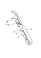
- FIG. 2 is a perspective view of the female terminal fitting shown in FIG.
- FIG. 3 is a perspective view of the connector housing shown in FIG.
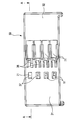
- FIG. 4 is a bottom view of the connector housing shown in FIG.
- FIG. 5 is a partially broken perspective view showing the structure of the bottom of the female terminal receiving hole of the connector housing shown in FIG. 6 (a) to 6 (c) are explanatory views of the process of inserting the terminal mounting jig into the jig insertion hole of the connector housing shown in FIG. 7 (a) and 7 (b) are explanatory views of the process of inserting the female terminal fitting into the female terminal receiving hole of the connector housing shown in FIG.
- FIG. 8 is a longitudinal sectional view of a conventional joint connector in an exploded state.
- FIG. 1 to 4 show an embodiment of a joint connector device according to the present invention
- FIG. 1 is an exploded perspective view of an embodiment of the joint connector device according to the present invention
- FIG. 2 is shown in FIG.
- FIG. 3 is a perspective view of the female terminal fitting viewed obliquely from the front end side
- FIG. 3 is a perspective view of the connector housing shown obliquely from the other end side of the connector housing shown in FIG. 1, and FIG. It is.
- the joint connector 1 includes a joint terminal 10, a female terminal fitting 20, and a resin connector housing 30.
- the joint terminal 10 is a press-molded product of a metal plate, and includes a plurality of tab pieces 11 for fitting and connecting the female terminal fitting 20 and a connecting portion 12 that electrically connects these tab pieces 11.
- the female terminal fitting 20 is a press-formed product of a metal plate, and extends from a rectangular tube-shaped box portion 21 into which the tab piece 11 is fitted and a rear end of the box portion 21 as shown in FIGS. 1 and 2.
- An electric wire caulking portion 22 for taking out and crimping an electric wire, an engagement concave portion 23 for preventing the removal, and an insertion guide protrusion 24 are provided.
- the electric wire crimping portion 22 includes a conductor crimping piece 22a for crimping the conductor of the electric wire and a covering crimping piece 22b for fixing the electric wire by crimping the electric wire covering portion.
- the retaining recess 23 for retaining is a recess formed on the rear end side of the box portion 21.
- the insertion guide protrusion 24 is a tongue-like piece extending along the insertion direction into the female terminal receiving hole of the connector housing 30 described later at a position near the rear end of the box portion 21.
- the insertion guide protrusion 24 is formed in a tongue shape by extending a part of the side wall of the box portion 21 and bending it.
- the connector housing 30 is a resin injection-molded product, and includes a housing one end portion 31 and a housing other end portion 32 that is an end portion opposite to the housing one end portion 31.
- the housing one end portion 31 accommodates and holds the joint terminal 10 with the tab piece 11 facing the housing other end portion 32 side.
- a plurality of female terminal receiving holes 34 are arranged as shown in FIGS.
- the plurality of female terminal receiving holes 34 are holes that bring the female terminal fitting 20 and the tab piece 11 into a fitted state by inserting the female terminal fitting 20 to a specified position.
- the specified position is a position at which the tab piece 11 and the box portion 21 obtain a contact length necessary and sufficient for electrical connection.
- a guide groove 35 is provided in the female terminal accommodation hole 34.
- the guide groove 35 slidably accommodates the insertion guide protrusion 24 and guides the female terminal fitting 20 to a specified position.
- the lower wall of the connector housing 30 corresponds to the position of each female terminal receiving hole 34 so as to communicate with each female terminal receiving hole 34 as shown in FIGS. 3 to 6C.
- a lance 36, a tab visual recognition window 37, and a jig insertion hole 38 are provided.
- the lance 36 protrudes from an elastic piece 36a extending along the female terminal accommodating hole 34 and a free end (right end in FIG. 5) of the elastic piece 36a.
- the terminal locking protrusion 36b protrudes toward the female terminal accommodating hole 34, and engages with the engaging recess 23 of the female terminal fitting 20 inserted at the specified position as shown in FIG. 7B. Then, the female terminal fitting 20 is prevented from coming off.
- the jig connecting projection 36c is provided at the free end of the lance 36 in a protruding shape protruding toward the tab piece 11 as shown in FIGS. 5 to 6C.
- the jig connecting convex portion 36c is a portion with which a terminal mounting jig 41 described later is engaged.
- the tab visualizing window portion 37 is opened at a position where the tip of the tab piece 11 can be seen, and the state in which the box portion 21 is fitted to the tab piece 11 can be seen. is there.
- the jig insertion hole 38 is an opening for inserting the terminal mounting jig 41 of the connector assembling apparatus 40 shown in FIGS. 6 (a) to 7 (b).
- the jig insertion hole 38 is formed through the outer wall of the housing so that the free end of the lance 36 including the jig connecting projection 36c and the peripheral edge thereof are exposed to the outer surface.
- the connector housing 30 is assembled before the female terminal fitting 20 is mounted in the female terminal accommodating hole 34 of the connector housing 30, as shown in FIGS. 6 (a) to 7 (b).
- the connector assembling apparatus 40 includes a base portion 42 on which the lower wall of the connector housing 30 having the jig insertion hole 38 is placed, End abutment that restricts movement of the connector housing 30 in the insertion direction of the female terminal fitting 20 (in the direction of arrow X2 in FIG. 6A) by abutting against one end surface of the connector housing 30 placed on the portion 42 And a terminal mounting jig 41 to be inserted into the jig insertion hole 38.
- the terminal mounting jig 41 is incorporated in the base portion 42 as shown in FIGS. 6 (a) to 6 (c).
- the terminal mounting jig 41 incorporated in the base portion 42 is movable in the vertical direction indicated by arrows Y1 and Y2 in FIGS. 6A to 6C and the terminal engagement direction indicated by arrow X3. It is supported.
- the terminal mounting jig 41 includes a hook-shaped jig main body 41a hooked on the jig connecting convex portion 36c and a disengagement formed on the jig main body 41a. Projecting portion 41b.
- the terminal mounting jig 41 is pulled up against the tensile force of the spring 45 (not shown). By the means, it is pulled up in the direction of the arrow Y1 (upward in FIG. 6 (a)) and is inserted into the jig insertion hole 38 as shown in FIG. 6 (b). It is positioned at a height at which it can be engaged with the jig connecting projection 36c.
- the terminal mounting jig 41 positioned at a height that can be engaged with the jig connecting convex portion 36c is slid in the direction of the arrow X3 in FIG. 6 (c), the jig main body 41a is engaged with the jig connecting convex part 36c. Further, the terminal mounting jig 41 engaged with the jig connecting convex portion 36c is urged in the direction indicated by the arrow Y2 in FIG. The urging in the direction of the arrow Y2 is performed by a tensile force by the spring 45 or an urging means (not shown).
- the free end side of the lance 36 is bent and deformed in the direction of retreating from the female terminal accommodating hole 34 as shown in FIG. 7 (a). Due to the bending deformation of the lance 36 in the retracting direction from the female terminal receiving hole 34, the terminal locking projection 36b of the lance 36 does not interfere with the female terminal fitting 20 inserted into the female terminal receiving hole 34, or the interference. Is lowered to a position where it greatly decreases.
- An arrow X4 shown in FIG. 7A indicates the insertion direction of the female terminal fitting 20.
- the insertion guide protrusion 24 that is a part on the female terminal fitting 20 is used for releasing the engagement on the terminal mounting jig 41. 7b, the terminal mounting jig 41 and the lance 36 are engaged with each other by the interference between the insertion guide protrusion 24 and the engagement release protrusion 41b. Canceled. As shown in FIG. 7B, the terminal mounting jig 41 released from the engagement with the lance 36 is then returned to the initial state embedded in the base portion 42 by the tensile force of the spring 45.
- the terminal mounting jig 41 when the terminal mounting jig 41 is assembled to the connector housing 30 before the female terminal fitting 20 is mounted, the jig body 41a inserted into the jig insertion hole 38 is inserted into the lance 36.
- the lance 36 is bent and deformed so that the terminal locking projection 36b of the lance 36 is retracted from the female terminal accommodating hole 34 by engaging with the free end.
- the terminal mounting jig 41 is connected to the jig main body 41a by interference with a portion on the female terminal fitting 20 (insertion guide protrusion 24) when the female terminal fitting 20 reaches the specified position.
- the engagement with the lance 36 is released, and the lance 36 is returned to a state in which the female terminal fitting 20 is prevented from coming off.
- the insertion guide protrusion 24 on the female terminal fitting 20 that slides in the guide groove 35 of the connector housing 30 when inserted into the female terminal receiving hole 34 is such that the female terminal fitting 20 is female.
- the terminal mounting jig 41 When it reaches the specified position in the terminal receiving hole 34, it also abuts on the terminal mounting jig 41 and functions as an engagement release means for releasing the engagement between the terminal mounting jig 41 and the lance 36.
- the joint connection between the joint terminal 10 and the female terminal fitting 20 is such that the joint terminal 10 is accommodated and held at one end and the female terminal fitting 20 at the other end. Therefore, the number of parts can be reduced as compared with a conventional joint connector in which a pair of connector housings are fitted and connected to each other.
- the female terminal fitting 20 is prevented from being detached from the connector housing 30 by the engagement between the lance 36 provided in the connector housing 30 and the engaging recess 23 of the female terminal fitting 20.
- the lance 36 is retracted from the female terminal accommodation hole 34 by the terminal mounting jig 41.
- the resistance by the lance 36 does not act on the female terminal fitting 20, so that the insertion operation of the female terminal fitting 20 becomes easy and the assemblability is improved. Can be planned.
- the terminal mounting jig 41 is mounted on the connector housing 30 in the state of FIGS. As shown in FIGS. 7A and 7B, when the female terminal fitting 20 is inserted to the specified position of the female terminal receiving hole 34, the insertion guide protrusion 24 provided in the female terminal fitting 20 is a terminal. Abutting against the mounting jig 41, the engagement between the terminal mounting jig 41 and the lance 36 is released.
- the jig body 41 a of the terminal mounting jig 41 mounted on the connector housing 30 is engaged with the lance 36 until the female terminal fitting 20 reaches the specified position of the female terminal receiving hole 34. Is maintained. Accordingly, whether or not the female terminal fitting 20 attached to the connector housing 30 is in a half-fitted state can be detected based on whether or not the engagement between the terminal attachment jig 41 and the lance 36 is released. it can. Therefore, since it is not necessary to equip the connector housing 30 with a dedicated half-fitting detection structure, the structure of the connector housing 30 can be simplified.
- joint connector device of the present invention is not limited to the above-described embodiments, and appropriate modifications and improvements can be made.
- the means for moving the terminal mounting jig in the direction of the arrow X3 in FIG. 6B is, for example, an appropriate mechanism by manual operation, or an electric movement mechanism using a motor or solenoid. It may be used.
- various known moving mechanisms can be used as the mechanism for driving the terminal mounting jig forward and backward.
- the fitting connection between the joint terminal and the female terminal fitting is performed by a single connector housing in which the joint terminal is accommodated and held at one end and the female terminal fitting is inserted at the other end. Therefore, the number of parts can be reduced as compared with a conventional joint connector in which a pair of connector housings are connected to each other.
Landscapes
- Engineering & Computer Science (AREA)
- Manufacturing & Machinery (AREA)
- Connector Housings Or Holding Contact Members (AREA)
- Details Of Connecting Devices For Male And Female Coupling (AREA)
Abstract
Description
このジョイントコネクタ100は、下記特許文献1に開示されたもので、ジョイント端子(バスバー)110と、複数本の雌型端子金具120と、第1のコネクタハウジング130と、第2のコネクタハウジング140と、を備えている。
(1) 複数本の雌型端子金具と、
前記雌型端子金具を嵌合接続する複数本のタブ片とこれらのタブ片を導通接続した連結部とを備えたジョイント端子と、
前記タブ片をハウジングの他端側に向けて前記ジョイント端子を収容保持するハウジング一端部と、前記雌型端子金具を規定位置まで挿入することで前記雌型端子金具と前記タブ片とを嵌合状態にする雌端子収容孔が配列されたハウジング他端部と、前記雌端子収容孔に沿って延出する弾性片の自由端側に前記雌端子収容孔に向かって突出する端子係止突起を備えて前記規定位置に挿入された前記雌型端子金具を前記端子係止突起により抜け止めするランスと、前記ランスの自由端側を外面に露出させるようにハウジング外壁に貫通形成された複数の治具挿通穴と、を有する樹脂製のコネクタハウジングと、
前記雌型端子金具の装着前に前記コネクタハウジングに組み付けられると、前記治具挿通穴に挿入される治具本体を前記ランスの自由端に係合させて、前記端子係止突起が前記雌端子収容孔から退避するように前記ランスを撓み変形させると共に、前記雌型端子金具が前記規定位置に到達したときに、前記雌型端子金具上の部位との干渉により、前記治具本体とランスとの係合が解除されて、前記雌型端子金具を抜け止めする状態に前記ランスを戻す端子装着用治具と、を備えたジョイントコネクタ装置。
前記コネクタハウジングは、前記雌型端子金具の雌端子収容孔への挿入時に前記挿入案内用突片を摺動可能に収容して前記雌型端子金具を前記規定位置に案内するガイド溝を備え、
前記雌型端子金具が前記規定位置に到達したときに、前記挿入案内用突片が前記治具本体に突き当たって、前記治具本体と前記ランスとの係合を解除する上記(1)に記載のジョイントコネクタ装置。
ガイド溝35は、雌型端子金具20の雌端子収容孔34への挿入時に、挿入案内用突片24を摺動可能に収容して、雌型端子金具20を規定位置に案内する。
基台部42に組み込まれた端子装着用治具41は、図6(a)~図6(c)に矢印Y1,Y2に示す上下方向、及び矢印X3で示す端子係合方向に移動可能に支持されている。
10 ジョイント端子
11 タブ片
20 雌型端子金具
21 箱部
24 挿入案内用突片(部位)
30 コネクタハウジング
31 ハウジング一端部
32 ハウジング他端部
34 雌端子収容孔
35 ガイド溝
36 ランス
36b 端子係止突起
36c 治具連結用凸部
37 タブ視認用窓部
38 治具挿通穴
40 コネクタ組み立て装置
41 端子装着用治具
41a 治具本体
41b 係合解除用突起部
42 基台部
43 端部当接部
45 バネ
Claims (2)
- 複数本の雌型端子金具と、
前記雌型端子金具を嵌合接続する複数本のタブ片とこれらのタブ片を導通接続した連結部とを備えたジョイント端子と、
前記タブ片をハウジングの他端側に向けて前記ジョイント端子を収容保持するハウジング一端部と、前記雌型端子金具を規定位置まで挿入することで前記雌型端子金具と前記タブ片とを嵌合状態にする雌端子収容孔が配列されたハウジング他端部と、前記雌端子収容孔に沿って延出する弾性片の自由端側に前記雌端子収容孔に向かって突出する端子係止突起を備えて前記規定位置に挿入された前記雌型端子金具を前記端子係止突起により抜け止めするランスと、前記ランスの自由端側を外面に露出させるようにハウジング外壁に貫通形成された複数の治具挿通穴と、を有する樹脂製のコネクタハウジングと、
前記雌型端子金具の装着前に前記コネクタハウジングに組み付けられると、前記治具挿通穴に挿入される治具本体を前記ランスの自由端に係合させて、前記端子係止突起が前記雌端子収容孔から退避するように前記ランスを撓み変形させると共に、前記雌型端子金具が前記規定位置に到達したときに、前記雌型端子金具上の部位との干渉により、前記治具本体とランスとの係合が解除されて、前記雌型端子金具を抜け止めする状態に前記ランスを戻す端子装着用治具と、を備えたジョイントコネクタ装置。 - 前記雌型端子金具は、前記雌端子収容孔への挿入方向に沿って延在する挿入案内用突片を備え、
前記コネクタハウジングは、前記雌型端子金具の雌端子収容孔への挿入時に前記挿入案内用突片を摺動可能に収容して前記雌型端子金具を前記規定位置に案内するガイド溝を備え、
前記雌型端子金具が前記規定位置に到達したときに、前記挿入案内用突片が前記治具本体に突き当たって、前記治具本体と前記ランスとの係合を解除する請求項1に記載のジョイントコネクタ装置。
Priority Applications (3)
| Application Number | Priority Date | Filing Date | Title |
|---|---|---|---|
| US13/982,907 US20130305527A1 (en) | 2011-02-15 | 2012-02-09 | Joint Connector Unit |
| CN2012800090647A CN103370839A (zh) | 2011-02-15 | 2012-02-09 | 接合连接器单元 |
| DE112012000838T DE112012000838T5 (de) | 2011-02-15 | 2012-02-09 | Kammverbindereinheit |
Applications Claiming Priority (2)
| Application Number | Priority Date | Filing Date | Title |
|---|---|---|---|
| JP2011-030099 | 2011-02-15 | ||
| JP2011030099A JP2012169185A (ja) | 2011-02-15 | 2011-02-15 | ジョイントコネクタ装置 |
Publications (1)
| Publication Number | Publication Date |
|---|---|
| WO2012111528A1 true WO2012111528A1 (ja) | 2012-08-23 |
Family
ID=46672454
Family Applications (1)
| Application Number | Title | Priority Date | Filing Date |
|---|---|---|---|
| PCT/JP2012/053006 Ceased WO2012111528A1 (ja) | 2011-02-15 | 2012-02-09 | ジョイントコネクタ装置 |
Country Status (6)
| Country | Link |
|---|---|
| US (1) | US20130305527A1 (ja) |
| JP (1) | JP2012169185A (ja) |
| CN (1) | CN103370839A (ja) |
| DE (1) | DE112012000838T5 (ja) |
| TW (1) | TWI433402B (ja) |
| WO (1) | WO2012111528A1 (ja) |
Families Citing this family (2)
| Publication number | Priority date | Publication date | Assignee | Title |
|---|---|---|---|---|
| JP6141612B2 (ja) * | 2012-09-21 | 2017-06-07 | 矢崎総業株式会社 | コネクタ |
| JP7361550B2 (ja) * | 2019-09-20 | 2023-10-16 | タイコエレクトロニクスジャパン合同会社 | コネクタ |
Citations (5)
| Publication number | Priority date | Publication date | Assignee | Title |
|---|---|---|---|---|
| JPH0680270U (ja) * | 1993-04-26 | 1994-11-08 | 住友電装株式会社 | コネクタ |
| JP2001250597A (ja) * | 2000-03-03 | 2001-09-14 | Yazaki Corp | 圧接コネクタ |
| JP2010040508A (ja) * | 2008-07-08 | 2010-02-18 | Sumitomo Wiring Syst Ltd | コネクタおよびワイヤハーネス |
| JP2010055940A (ja) * | 2008-08-28 | 2010-03-11 | Autonetworks Technologies Ltd | ワイヤハーネスのコネクタホルダ並びにワイヤハーネスの製造方法 |
| JP2010067483A (ja) * | 2008-09-11 | 2010-03-25 | Sumitomo Wiring Syst Ltd | ジョイントコネクタおよびジョイントコネクタ付きワイヤハーネス |
Family Cites Families (3)
| Publication number | Priority date | Publication date | Assignee | Title |
|---|---|---|---|---|
| JPH08250185A (ja) | 1995-01-13 | 1996-09-27 | Sumitomo Wiring Syst Ltd | ジョイントコネクタ及びジョイントコネクタ用キャップ |
| CN101630790A (zh) * | 2008-07-08 | 2010-01-20 | 住友电装株式会社 | 连接器、设置有该连接器的线束以及连接方法 |
| JP5353529B2 (ja) | 2009-07-28 | 2013-11-27 | 富士通株式会社 | 通信システム、サーバ装置、通信制御方法及びコンピュータプログラム |
-
2011
- 2011-02-15 JP JP2011030099A patent/JP2012169185A/ja not_active Ceased
-
2012
- 2012-02-09 CN CN2012800090647A patent/CN103370839A/zh active Pending
- 2012-02-09 WO PCT/JP2012/053006 patent/WO2012111528A1/ja not_active Ceased
- 2012-02-09 US US13/982,907 patent/US20130305527A1/en not_active Abandoned
- 2012-02-09 DE DE112012000838T patent/DE112012000838T5/de not_active Withdrawn
- 2012-02-15 TW TW101104886A patent/TWI433402B/zh not_active IP Right Cessation
Patent Citations (5)
| Publication number | Priority date | Publication date | Assignee | Title |
|---|---|---|---|---|
| JPH0680270U (ja) * | 1993-04-26 | 1994-11-08 | 住友電装株式会社 | コネクタ |
| JP2001250597A (ja) * | 2000-03-03 | 2001-09-14 | Yazaki Corp | 圧接コネクタ |
| JP2010040508A (ja) * | 2008-07-08 | 2010-02-18 | Sumitomo Wiring Syst Ltd | コネクタおよびワイヤハーネス |
| JP2010055940A (ja) * | 2008-08-28 | 2010-03-11 | Autonetworks Technologies Ltd | ワイヤハーネスのコネクタホルダ並びにワイヤハーネスの製造方法 |
| JP2010067483A (ja) * | 2008-09-11 | 2010-03-25 | Sumitomo Wiring Syst Ltd | ジョイントコネクタおよびジョイントコネクタ付きワイヤハーネス |
Also Published As
| Publication number | Publication date |
|---|---|
| JP2012169185A (ja) | 2012-09-06 |
| US20130305527A1 (en) | 2013-11-21 |
| CN103370839A (zh) | 2013-10-23 |
| TW201246705A (en) | 2012-11-16 |
| TWI433402B (zh) | 2014-04-01 |
| DE112012000838T5 (de) | 2013-11-14 |
Similar Documents
| Publication | Publication Date | Title |
|---|---|---|
| EP1936749B1 (en) | A terminal fitting, a connector and a forming method | |
| JP5285985B2 (ja) | 雌型端子金具 | |
| JP4963702B2 (ja) | 端子位置保証装置を有するコネクタ組立体 | |
| CN114175405B (zh) | 连接器 | |
| JP2012169186A (ja) | ジョイントコネクタ | |
| CN104662742A (zh) | 连接器 | |
| JP5614792B2 (ja) | 分割コネクタ | |
| CN101335396B (zh) | 连接器及其组装方法 | |
| KR20110061553A (ko) | 전기 커넥터 | |
| WO2012111572A1 (ja) | コネクタ及び該コネクタの組立用治具 | |
| EP3879637B1 (en) | Connector lock structure | |
| CN110383595A (zh) | 连接器 | |
| TWI433402B (zh) | Joint connector device | |
| JP2002367701A (ja) | コネクタ | |
| US20230102502A1 (en) | Connector | |
| CN101295830A (zh) | L型接触件 | |
| WO2012111529A1 (ja) | ジョイントコネクタ、及びコネクタ組み立て装置 | |
| JP4893452B2 (ja) | コネクタ | |
| CN116057788A (zh) | 屏蔽连接器 | |
| JP5071732B2 (ja) | 電線カバー付きコネクタ | |
| JPH11195456A (ja) | ロック機構付コネクタ | |
| JP2020126826A (ja) | ハウジング及びコネクタ | |
| CN111146613B (zh) | 端子,将电线连接到端子的方法,以及夹具 | |
| JP4089604B2 (ja) | コネクタ | |
| JP7337946B2 (ja) | コネクタ |
Legal Events
| Date | Code | Title | Description |
|---|---|---|---|
| 121 | Ep: the epo has been informed by wipo that ep was designated in this application |
Ref document number: 12747697 Country of ref document: EP Kind code of ref document: A1 |
|
| WWE | Wipo information: entry into national phase |
Ref document number: 13982907 Country of ref document: US |
|
| WWE | Wipo information: entry into national phase |
Ref document number: 1120120008383 Country of ref document: DE Ref document number: 112012000838 Country of ref document: DE |
|
| 122 | Ep: pct application non-entry in european phase |
Ref document number: 12747697 Country of ref document: EP Kind code of ref document: A1 |