WO2012111359A1 - テンプレート処理方法、コンピュータ記憶媒体、テンプレート処理装置及びインプリントシステム - Google Patents
テンプレート処理方法、コンピュータ記憶媒体、テンプレート処理装置及びインプリントシステム Download PDFInfo
- Publication number
- WO2012111359A1 WO2012111359A1 PCT/JP2012/050251 JP2012050251W WO2012111359A1 WO 2012111359 A1 WO2012111359 A1 WO 2012111359A1 JP 2012050251 W JP2012050251 W JP 2012050251W WO 2012111359 A1 WO2012111359 A1 WO 2012111359A1
- Authority
- WO
- WIPO (PCT)
- Prior art keywords
- template
- cleaning liquid
- unit
- release film
- pure water
- Prior art date
- Legal status (The legal status is an assumption and is not a legal conclusion. Google has not performed a legal analysis and makes no representation as to the accuracy of the status listed.)
- Ceased
Links
Images








Classifications
-
- G—PHYSICS
- G03—PHOTOGRAPHY; CINEMATOGRAPHY; ANALOGOUS TECHNIQUES USING WAVES OTHER THAN OPTICAL WAVES; ELECTROGRAPHY; HOLOGRAPHY
- G03F—PHOTOMECHANICAL PRODUCTION OF TEXTURED OR PATTERNED SURFACES, e.g. FOR PRINTING, FOR PROCESSING OF SEMICONDUCTOR DEVICES; MATERIALS THEREFOR; ORIGINALS THEREFOR; APPARATUS SPECIALLY ADAPTED THEREFOR
- G03F7/00—Photomechanical, e.g. photolithographic, production of textured or patterned surfaces, e.g. printing surfaces; Materials therefor, e.g. comprising photoresists; Apparatus specially adapted therefor
- G03F7/0002—Lithographic processes using patterning methods other than those involving the exposure to radiation, e.g. by stamping
-
- B—PERFORMING OPERATIONS; TRANSPORTING
- B29—WORKING OF PLASTICS; WORKING OF SUBSTANCES IN A PLASTIC STATE IN GENERAL
- B29C—SHAPING OR JOINING OF PLASTICS; SHAPING OF MATERIAL IN A PLASTIC STATE, NOT OTHERWISE PROVIDED FOR; AFTER-TREATMENT OF THE SHAPED PRODUCTS, e.g. REPAIRING
- B29C33/00—Moulds or cores; Details thereof or accessories therefor
- B29C33/38—Moulds or cores; Details thereof or accessories therefor characterised by the material or the manufacturing process
- B29C33/3842—Manufacturing moulds, e.g. shaping the mould surface by machining
- B29C33/3857—Manufacturing moulds, e.g. shaping the mould surface by machining by making impressions of one or more parts of models, e.g. shaped articles and including possible subsequent assembly of the parts
-
- B—PERFORMING OPERATIONS; TRANSPORTING
- B82—NANOTECHNOLOGY
- B82Y—SPECIFIC USES OR APPLICATIONS OF NANOSTRUCTURES; MEASUREMENT OR ANALYSIS OF NANOSTRUCTURES; MANUFACTURE OR TREATMENT OF NANOSTRUCTURES
- B82Y10/00—Nanotechnology for information processing, storage or transmission, e.g. quantum computing or single electron logic
-
- B—PERFORMING OPERATIONS; TRANSPORTING
- B82—NANOTECHNOLOGY
- B82Y—SPECIFIC USES OR APPLICATIONS OF NANOSTRUCTURES; MEASUREMENT OR ANALYSIS OF NANOSTRUCTURES; MANUFACTURE OR TREATMENT OF NANOSTRUCTURES
- B82Y40/00—Manufacture or treatment of nanostructures
-
- H—ELECTRICITY
- H10—SEMICONDUCTOR DEVICES; ELECTRIC SOLID-STATE DEVICES NOT OTHERWISE PROVIDED FOR
- H10P—GENERIC PROCESSES OR APPARATUS FOR THE MANUFACTURE OR TREATMENT OF DEVICES COVERED BY CLASS H10
- H10P72/00—Handling or holding of wafers, substrates or devices during manufacture or treatment thereof
- H10P72/04—Apparatus for manufacture or treatment
- H10P72/0402—Apparatus for fluid treatment
- H10P72/0406—Apparatus for fluid treatment for cleaning followed by drying, rinsing, stripping, blasting or the like
-
- H—ELECTRICITY
- H10—SEMICONDUCTOR DEVICES; ELECTRIC SOLID-STATE DEVICES NOT OTHERWISE PROVIDED FOR
- H10P—GENERIC PROCESSES OR APPARATUS FOR THE MANUFACTURE OR TREATMENT OF DEVICES COVERED BY CLASS H10
- H10P72/00—Handling or holding of wafers, substrates or devices during manufacture or treatment thereof
- H10P72/04—Apparatus for manufacture or treatment
- H10P72/0402—Apparatus for fluid treatment
- H10P72/0406—Apparatus for fluid treatment for cleaning followed by drying, rinsing, stripping, blasting or the like
- H10P72/0411—Apparatus for fluid treatment for cleaning followed by drying, rinsing, stripping, blasting or the like for wet cleaning or washing
- H10P72/0414—Apparatus for fluid treatment for cleaning followed by drying, rinsing, stripping, blasting or the like for wet cleaning or washing using mainly spraying means, e.g. nozzles
-
- H—ELECTRICITY
- H10—SEMICONDUCTOR DEVICES; ELECTRIC SOLID-STATE DEVICES NOT OTHERWISE PROVIDED FOR
- H10P—GENERIC PROCESSES OR APPARATUS FOR THE MANUFACTURE OR TREATMENT OF DEVICES COVERED BY CLASS H10
- H10P72/00—Handling or holding of wafers, substrates or devices during manufacture or treatment thereof
- H10P72/04—Apparatus for manufacture or treatment
- H10P72/0431—Apparatus for thermal treatment
- H10P72/0436—Apparatus for thermal treatment mainly by radiation
-
- B—PERFORMING OPERATIONS; TRANSPORTING
- B29—WORKING OF PLASTICS; WORKING OF SUBSTANCES IN A PLASTIC STATE IN GENERAL
- B29C—SHAPING OR JOINING OF PLASTICS; SHAPING OF MATERIAL IN A PLASTIC STATE, NOT OTHERWISE PROVIDED FOR; AFTER-TREATMENT OF THE SHAPED PRODUCTS, e.g. REPAIRING
- B29C33/00—Moulds or cores; Details thereof or accessories therefor
- B29C33/56—Coatings, e.g. enameled or galvanised; Releasing, lubricating or separating agents
- B29C33/68—Release sheets
Definitions
- the present invention relates to a template processing method, a computer storage medium, a template processing apparatus, and an imprint system for removing a release film formed on a transfer pattern on a surface of a template and cleaning the surface of the template.
- a semiconductor wafer (hereinafter referred to as “wafer”) is subjected to a photolithography process to form a predetermined resist pattern on the wafer.
- the resist pattern When forming the above-described resist pattern, the resist pattern is required to be miniaturized in order to further increase the integration of the semiconductor device.
- the limit of miniaturization in the photolithography process is about the wavelength of light used for the exposure process. For this reason, it has been advancing to shorten the wavelength of exposure light.
- there are technical and cost limitations to shortening the wavelength of the exposure light source and it is difficult to form a fine resist pattern on the order of several nanometers, for example, only by the method of advancing the wavelength of light. is there.
- a release film having liquid repellency is usually formed on the surface of the template used in the above-described imprinting method so that the template can be easily peeled off from the resist.
- this imprint method is repeated, that is, when a plurality of resist patterns are formed on a plurality of wafers using a single template, the release film on the template deteriorates. For this reason, it is necessary to collect and replace a used template.
- the present invention has been made in view of such points, and an object thereof is to efficiently remove a release film formed on the surface of a template and efficiently clean the surface of the template.
- the present invention provides a template processing method for cleaning a surface of a template by removing a release film formed on a transfer pattern on the surface of the template. While irradiating the release film with ultraviolet rays from the back side of the template, a cleaning liquid is supplied to the release film from the front side of the template to clean the surface of the template.
- the cleaning liquid when cleaning the surface of the template, the cleaning liquid is supplied to the release film from the front surface side of the template while irradiating the release film with ultraviolet light from the back side of the template. Are supplied from different directions. For this reason, ultraviolet rays do not pass through the cleaning liquid, and the ultraviolet rays do not attenuate. Accordingly, the energy of ultraviolet rays can be utilized to the maximum, and the release film on the template can be appropriately irradiated with ultraviolet rays. As a result, the release film on the surface of the template can be efficiently removed, and the surface of the template can be efficiently cleaned.
- Another aspect of the present invention is a readable computer storage medium storing a program that operates on a computer of a control unit that controls the template processing apparatus in order to cause the template processing apparatus to execute the template processing method.
- Another aspect of the present invention is a template processing apparatus that removes a release film formed on a transfer pattern on the surface of a template and cleans the surface of the template, and includes a holding unit that holds the template. Irradiating the mold release film on the surface of the template with ultraviolet light from the back side of the template to the liquid supply unit for supplying the cleaning liquid from the surface side of the template and the mold release film on the surface of the template And an ultraviolet irradiation unit.
- an imprint system including the template processing apparatus, wherein the transfer pattern is formed on a substrate using the template having a release film formed on a surface thereof. It has an imprint apparatus that transfers to a film and forms a predetermined pattern on the coating film.
- the release film formed on the surface of the template can be efficiently removed, and the surface of the template can be efficiently cleaned.
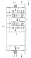
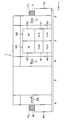
- FIG. 1 is a plan view showing an outline of a configuration of an imprint system 1 according to the present embodiment.
- 2 to 4 are side views each showing an outline of the configuration of the imprint system 1.
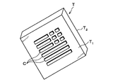
- a template T having a rectangular parallelepiped shape and having a predetermined transfer pattern C formed on the surface is used as shown in FIG.
- the transfer pattern C means the side of the template T which is formed with the surface T 1, the surface T 1 opposite to the surface of the backside T 2.
- a transparent material that can transmit visible light, near ultraviolet light, ultraviolet light, or the like, such as glass, is used.
- the imprint system 1 includes a template loading / unloading station 2, a processing station 3, an interface station 4, an imprint unit 5 as an imprinting device, and a wafer loading / unloading station 6 in the Y direction ( The left and right directions in FIG. 1 are integrally connected in this order.
- Template unloading station 2 a plurality, for example five template T or transferring, between the outside and the imprint system 1 in the cassette unit, or transferring, the template T with respect to the template cassette C T.
- the processing station 3 includes a plurality of processing units that perform predetermined processing on the template T.
- the interface station 4 delivers the template T between the processing station 3 and the imprint unit 5.
- the imprint unit 5 forms a resist pattern on the wafer W as a substrate using the template T.
- Station 6 out wafer carry a plurality, for example, or transferring, 25 wafers W between the outside and the imprint system 1 in the cassette unit, or transferring, the wafer W to the wafer cassette C W.
- the template loading / unloading station 2 is provided with a cassette mounting table 10.
- the cassette mounting table 10 can mount a plurality of template cassettes CT in a line in the X direction (vertical direction in FIG. 1). That is, the template carry-in / out station 2 is configured to be capable of holding a plurality of templates T.
- the template carry-in / out station 2 is provided with a template carrier 12 that can move on a conveyance path 11 extending in the X direction.
- Template carrier 12 is also movable in the vertical direction and the vertical around (theta direction), can transfer the template T with the template cassette C T and the imprint unit 5.
- the processing station 3 is provided with a transport unit 20 at the center thereof.
- a transport unit 20 for example, six processing blocks G1 to G6 in which various processing units are arranged in multiple stages are arranged.
- a first processing block G1 and a second processing block G2 are arranged in this order from the template loading / unloading station 2 side on the front side of the processing station 3 (X direction negative direction side in FIG. 1).
- a third processing block G3 is disposed on the template loading / unloading station 2 side of the processing station 3, and a fourth processing block G4 is disposed on the imprint unit 5 side of the processing station 3.
- a fifth processing block G5 and a sixth processing block G6 are arranged in this order from the template loading / unloading station 2 side on the back side of the processing station 3 (positive side in the X direction in FIG. 1).
- the transport unit 20 can transport the template T to various processing units (described later) arranged in these processing blocks G1 to G6.
- the first processing block G1 includes a plurality of liquid processing units, for example, a coating unit 21 for applying a liquid release agent to the template T, and a rinse unit for rinsing the release agent on the template T. 22 are stacked in two steps from the bottom.
- the coating unit 23 and the rinsing unit 24 are stacked in two stages from the bottom.
- chemical chambers 25 and 26 for supplying various processing liquids to the liquid processing unit are provided at the lowermost stages of the first processing block G1 and the second processing block G2, respectively.
- a material having a liquid repellency with respect to a resist film on the wafer which will be described later, is used as the material of the release agent.
- a liquid release agent is used, but a gaseous release agent may be used.
- the third processing block G3, ultraviolet rays are irradiated to the template T as shown in FIG. 3, the cleaning unit 30 before the pre-cleaning the surface T 1 a release film on the template T is deposited, Temperature control units 31 and 32 for adjusting the temperature of the template T, a transition unit 33 for transferring the template T, and heating units 34 and 35 for heat-treating the template T are stacked in six stages from the bottom.
- the pre-cleaning unit 40, the temperature control units 41 and 42, the transition unit 43, and the heating units 44 and 45 are stacked in the fourth processing block G4 in order from the bottom in six stages. Yes.
- the fifth processing block G5 to clean the surface T 1 of the template T after use, as shown in FIG. 4, the cleaning units 50 and 51 after the template processing apparatus according to this embodiment, the template after washing inspection unit 52 for inspecting the surface T 1 of the T are stacked in three stages in order from the bottom.
- post-cleaning units 60 and 61 and an inspection unit 62 are stacked in three stages in order from the bottom.
- the interface station 4 is provided with a template transport body 71 that moves on a transport path 70 extending in the X direction as shown in FIG.
- a reversing unit 72 that reverses the front and back surfaces of the template T is disposed on the positive side in the X direction of the transport path 70.
- a buffer cassette 73 for temporarily storing a plurality of templates T is disposed on the negative side of the conveyance path 70 in the X direction.
- the template transport body 71 is also movable in the vertical direction and around the vertical direction ( ⁇ direction), and can transport the template T between the processing station 3, the reversing unit 72, the buffer cassette 73, and the imprint unit 5.
- the wafer loading / unloading station 6 is provided with a cassette mounting table 80.
- the cassette mounting table 80 can mount a plurality of wafer cassettes CW in a row in the X direction (vertical direction in FIG. 1). That is, the wafer carry-in / out station 6 is configured to be capable of holding a plurality of wafers W.
- the wafer carry-in / out station 6 is provided with a wafer carrier 82 that can move on a conveyance path 81 extending in the X direction.
- the wafer transfer body 82 is also movable in the vertical direction and around the vertical direction ( ⁇ direction), and can transfer the wafer W between the wafer cassette CW and the imprint unit 5.
- the wafer carry-in / out station 6 is further provided with an alignment unit 83 for adjusting the orientation of the wafer W.
- the orientation of the wafer W is adjusted based on the position of the notch portion of the wafer W, for example.
- the imprint unit 5 includes a processing container 100 in which a loading / unloading port (not shown) for the template T and a loading / unloading port (not shown) for the wafer W are formed on the side surfaces.
- a wafer holder 101 on which the wafer W is placed and held is provided on the bottom surface in the processing container 100.
- the wafer W is placed on the upper surface of the wafer holder 101 so that the surface to be processed faces upward.
- lifting pins 102 are provided for supporting the wafer W from below and lifting it.
- the elevating pin 102 can be moved up and down by the elevating drive unit 103.
- a through hole 104 that penetrates the upper surface in the thickness direction is formed on the upper surface of the wafer holding unit 101, and the elevating pins 102 are inserted through the through hole 104. Further, the wafer holding unit 101 can be moved in the horizontal direction by the moving mechanism 105 provided below the wafer holding unit 101 and can be rotated around the vertical.
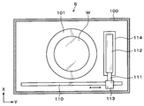
- a rail 110 extending along the Y direction (left and right direction in FIG. 7) is provided on the negative side in the X direction (downward direction in FIG. 7) of the wafer holding unit 101.
- the rail 110 is formed from the outer side of the wafer holding unit 101 on the Y direction negative direction (left direction in FIG. 7) to the outer side on the Y direction positive direction (right direction in FIG. 7).
- An arm 111 is attached to the rail 110.
- the arm 111 supports a resist solution nozzle 112 for supplying a resist solution onto the wafer W.
- the resist solution nozzle 112 has, for example, an elongated shape along the X direction that is the same as or longer than the diameter of the wafer W.
- an inkjet nozzle is used as the resist solution nozzle 112, and a plurality of supply ports (not shown) formed in a line along the longitudinal direction are formed below the resist solution nozzle 112.
- the resist solution nozzle 112 can strictly control the resist solution supply timing, the resist solution supply amount, and the like.
- the arm 111 is movable on the rail 110 by the nozzle driving unit 113.
- the resist solution nozzle 112 can move from the standby unit 114 installed on the outer side of the wafer holding unit 101 on the positive side in the Y direction to above the wafer W on the wafer holding unit 101, and the surface of the wafer W The top can be moved in the radial direction of the wafer W.
- the arm 111 can be moved up and down by a nozzle driving unit 113 and the height of the resist solution nozzle 112 can be adjusted.
- a template holding unit 120 that holds the template T is provided on the ceiling surface in the processing container 100 and above the wafer holding unit 101 as shown in FIG. That is, the wafer holding unit 101 and the template holding unit 120 are arranged so that the wafer W placed on the wafer holding unit 101 and the template T held on the template holding unit 120 face each other. Furthermore, the template holding portion 120 has a chuck 121 for holding adsorb outer peripheral portion of the rear surface T 2 of the template T.
- the chuck 121 is movable in the vertical direction and rotatable about the vertical by a moving mechanism 122 provided above the chuck 121. Thereby, the template T can be moved up and down in a predetermined direction with respect to the wafer W on the wafer holding unit 101.
- the template holding unit 120 has a light source 123 provided above the template T held by the chuck 121.
- the light source 123 emits light such as visible light, near ultraviolet light, and ultraviolet light, and the light from the light source 123 passes through the template T and is irradiated downward.
- the post-cleaning unit 50 has a processing container 150 in which a loading / unloading port (not shown) for the template T is formed on the side surface.
- a holding portion 151 that holds the back surface T ⁇ b > 2 of the template T is provided in the central portion in the processing container 150.
- a central portion of the holding portion 151 is depressed downward, and a storage portion 152 that stores the template T is formed.
- a groove portion 153 that is slightly smaller than the outer shape of the template T is formed in the lower portion of the housing portion 152 as shown in FIG. Accordingly, within the accommodating portion 152, the lower surface in the peripheral portion of the template T by the groove 153 does not contact with the holding portion 151, only the outer peripheral portion of the rear surface T 2 of the template T is supported by the holding portion 151.
- the accommodating portion 152 has a substantially rectangular planar shape that matches the outer shape of the template T.
- a plurality of projecting portions 154 projecting inward from the side surfaces are formed in the accommodating portion 152, and the template T accommodated in the accommodating portion 152 is positioned by the projecting portions 154. Further, when the template T is delivered from the transfer arm of the transfer unit 20 to the storage unit 152, four cutout portions 155 are provided on the outer periphery of the storage unit 152 in order to prevent the transfer arm from interfering with the storage unit 152. Is formed.
- the groove 153 is provided with an ultraviolet irradiation unit 160 that irradiates ultraviolet rays as shown in FIG.
- the ultraviolet irradiation unit 160 includes a lamp 161 that irradiates ultraviolet rays and a lamp house 162 that houses the lamp 161.
- the lamp 161 irradiates ultraviolet rays having a wavelength of 172 nm, for example.
- the lamp house 162 is made of a material that transmits ultraviolet rays, such as quartz.
- the holding part 151 is attached to the cover body 170 as shown in FIG. 8, and a rotation driving part 172 is provided below the holding part 151 via a shaft 171.
- this rotation driving unit 172 the holding unit 151 can rotate around the vertical at a predetermined speed and can move up and down.
- a cup 180 is provided as a collection unit that receives and collects the cleaning liquid and pure water scattered or dropped from the template T.
- a discharge pipe 181 that discharges the recovered cleaning liquid and pure water and an exhaust pipe 182 that exhausts the atmosphere in the cup 180 are connected to the lower surface of the cup 180.
- a rail 190 extending along the Y direction is formed on the X direction negative direction (downward direction in FIG. 9) side of the cup 180.
- the rail 190 is formed, for example, from the outer side of the cup 180 on the Y direction negative direction (left direction in FIG. 9) to the outer side on the Y direction positive direction (right direction in FIG. 9).
- An arm 191 is attached to the rail 190.
- the arm 191 supports a nozzle 192 that supplies cleaning liquid and pure water onto the template T.
- the arm 191 is movable on the rail 190 by a nozzle driving unit 193.
- the nozzle 192 can move from the standby portion 194 installed on the outer side of the cup 180 on the positive side in the Y direction to above the center portion of the template T in the cup 180.
- the arm 191 can be moved up and down by a nozzle driving unit 193, and the height of the nozzle 192 can be adjusted.
- the nozzle 192 has a double tube structure including an inner tube 200 and an outer tube 201 surrounding the inner tube 200 as shown in FIGS. 12 and 13.
- An end portion of the inner tube 200 is opened to form a cleaning liquid supply port 202 for supplying a cleaning liquid.
- the end of the outer tube 201 is also open.
- pipe 201 forms the pure water supply port 203 which supplies a pure water. That is, the pure water supply port 203 is formed in an annular shape around the cleaning liquid supply port 202.
- the inner tube 200 communicates with a cleaning liquid supply source 204 that supplies a cleaning liquid.
- a cleaning liquid for example, a fluorinated solvent is stored in the cleaning liquid supply source 204.
- This fluorine-based solvent is a solvent for a release agent, and is, for example, a hydrofluoroether (HFE).
- the cleaning liquid supplied from the cleaning liquid supply source 204 flows through the inner tube 200 and is supplied from the cleaning liquid supply port 202.
- the outer pipe 201 communicates with a pure water supply source 205 that stores and supplies pure water. Pure water has a lower specific gravity than the cleaning liquid and does not have an affinity for the cleaning liquid.
- the pure water supplied from the pure water supply source 205 flows between the inner pipe 200 and the outer pipe 201 and is supplied from the pure water supply port 203.
- the nozzle 192 can supply the cleaning liquid and pure water from the surface T 1 side of the template T to the release film S on the surface T 1 of the template T.
- the nozzle 192, the cleaning liquid supply source 204, and the pure water supply source 205 constitute a liquid supply unit.
- the separation part 210 which isolate
- the separation unit 210 is connected to the drainage pipe 181.
- the separation unit 210 has a storage container 211 that stores and separates the cleaning liquid F and pure water D discharged from the drain pipe 181 as shown in FIG.
- a pure water discharge pipe 212 for discharging pure water D and a cleaning liquid discharge pipe 213 for discharging cleaning liquid F are provided on the side surface of the storage container 211.
- the pure water discharge pipe 212 is disposed above the cleaning liquid discharge pipe 213.
- cleaning liquid F and the pure water D are isolate
- the separated pure water D and the cleaning liquid F are discharged from the pure water discharge pipe 212 and the cleaning liquid discharge pipe 213, respectively.
- a distillation unit 220 for distilling the cleaning liquid F separated by the separation unit 210 is provided outside the processing container 150 as shown in FIG.
- the distillation unit 220 is connected to the cleaning liquid discharge pipe 213 of the separation unit 210.
- the distillation unit 220 distills the cleaning liquid F discharged from the cleaning liquid discharge pipe 213 and mixed with the release film S as an impurity.
- the distillation unit 220 heats and evaporates the cleaning liquid F discharged from the cleaning liquid discharge pipe 213, the cooling pipe 222 that cools and vaporizes the vapor evaporated in the vaporization container 221, and the liquid is liquefied by the cooling pipe 222.
- a recovery container 223 for recovering the cleaning liquid F.
- One end of the cooling pipe 222 is connected to the upper surface of the vaporization container 221, and the other end of the cooling pipe 222 is connected to the upper surface of the recovery container 223.
- a heater 224 for heating the cleaning liquid F is provided on the bottom surface of the vaporization vessel 221.
- the heater 224 heats the cleaning liquid F at a temperature equal to or higher than its boiling point, evaporates the cleaning liquid F and vaporizes it.
- the boiling point thereof is 60 ° C. to 130 ° C.
- the release film S mixed in the cleaning liquid F is not vaporized. Therefore, only the cleaning liquid F is vaporized.
- the cleaning liquid F is heated and vaporized, but the inside of the vaporizing vessel 221 may be decompressed to vaporize the cleaning liquid F.
- a refrigerant supply source (not shown) that supplies a cooling medium having a boiling point of the cleaning liquid F or less is connected to the refrigerant flow pipe 225 with respect to the refrigerant flow pipe 225.
- the vapor inside the cooling pipe 222 is cooled and liquefied by the cooling medium flowing through the refrigerant flow pipe 225.
- the cleaning liquid F liquefied by the cooling pipe 222 flows into the recovery container 223.
- a recovery pipe 226 Connected to the side surface of the recovery container 223 is a recovery pipe 226 that recovers the cleaning liquid F that is distilled and does not contain impurities.
- the cleaning liquid F recovered from the recovery pipe 226 is stored in the cleaning liquid supply source 204, for example.
- the cleaning liquid F is reused for cleaning the surface T 1 of the template T in the post-cleaning unit 50.
- the configuration of the post-cleaning units 51, 60, and 61 is the same as the configuration of the post-cleaning unit 50 described above, and a description thereof will be omitted.
- the imprint system 1 described above is provided with a control unit 300 as shown in FIG.
- the control unit 300 is a computer, for example, and has a program storage unit (not shown).
- the program storage unit stores a program for executing an imprint process to be described later in the imprint system 1.
- This program is recorded in a computer-readable storage medium such as a computer-readable hard disk (HD), flexible disk (FD), compact disk (CD), magnetic optical desk (MO), memory card, or the like. Or installed in the control unit 300 from the storage medium.
- a computer-readable storage medium such as a computer-readable hard disk (HD), flexible disk (FD), compact disk (CD), magnetic optical desk (MO), memory card, or the like.
- the imprint system 1 according to the present embodiment is configured as described above. Next, an imprint process performed in the imprint system 1 will be described.
- FIG. 16 shows the main processing flow of this imprint processing
- FIG. 17 shows the state of the template T and the wafer W in each step.
- the template carrier 12 removes the template T from the template cassette CT on the cassette mounting table 10 and conveys it to the transition unit 33 in the third processing block G3 of the processing station 3 (step A1 in FIG. 16). ).
- the template cassette C T the template T, the surface T 1 of the transfer pattern C is formed is accommodated so as to face upward, the template T in this state is conveyed to the transition unit 33.
- the template T is transported to the pre-cleaning unit 30 by the transport unit 20.
- the pre-cleaning unit 30 ultraviolet rays are irradiated, for example, in surface T 1 the entire surface of the template T.
- impurities of the organic contaminants and particles of the surface T 1 of the template T is removed as shown in FIG. 17 (a), the surface T 1 is washed (step A2 in FIG. 16).
- the template T is transported to the coating unit 21 by the transport unit 20.
- a so-called spin coating method is performed in which a release agent is supplied from a nozzle to the center of the rotating template T and the release agent is diffused on the template T by centrifugal force.
- the release agent S 0 is applied to the surface T 1 the entire surface of the template T as shown in FIG. 17 (b) (step A3 in FIG. 16).
- the method of coating the release agent S 0 is not limited to the spin coating method described above may take a variety of ways.
- the release agent S 0 may be applied on the template T using a nozzle that extends in the width direction of the template T and has a slit-like supply port formed on the lower surface.
- the release agent S 0 is stored. been by immersing the template T in the immersion bath, the release agent S 0 may be applied on the template T.
- the template T is transported to the heating unit 34 by the transport unit 20.
- the template T is heated to 200 ° C., for example.
- the release agent S 0 on the template T is fired as shown in FIG. 17 (c) (step A4 in FIG. 16).
- the transport unit 20 transports the template T to the temperature adjustment unit 211, and the template T is adjusted to a predetermined temperature.
- the template T is transported to the rinse unit 22 by the transport unit 20.
- an organic solvent is supplied to the surface T 1 of the template T.
- the release film S along the transfer pattern C on the template T is deposited as shown in FIG. 17 (d) (Fig. 16 Step A5).
- the releasing agent unreacted portion of S 0 refers to a portion other than the portion where the release agent S 0 are adsorbed with the surface T 1 by the surface T 1 and the chemical reaction of the template T.
- the method of supplying an organic solvent to the surface T 1 of the template T may take a variety of ways.
- the template T may be immersed in an immersion tank storing an organic solvent, or the organic solvent may be supplied using a so-called spin coating method.
- the template T is transported by the transport unit 20 to the transition unit 43 of the fourth processing block G4. Subsequently, the template T is transported to the reversing unit 72 by the template transport body 71 of the interface station 4 so that the front and back surfaces of the template T are reversed. That is, the rear surface T 2 of the template T is directed upwards. Thereafter, the template T is transported to the imprint unit 5 by the template transport body 71 and sucked and held by the chuck 121 of the template holding unit 120.
- the wafer cassette C W on the cassette mounting table 80 is transferred by the wafer transfer body 82.
- the wafer W is taken out from the wafer and transferred to the alignment unit 83.
- the alignment unit 83 the orientation of the wafer W is adjusted based on the position of the notch portion of the wafer W.
- the wafer W is transferred to the imprint unit 5 by the wafer transfer body 82 (step A6 in FIG. 16). Note that, in the wafer carry-in / out station 6, the wafers W in the wafer cassette CW are accommodated so that their processing surfaces face upward, and in this state, the wafers W are transferred to the imprint unit 5.
- the wafer W carried into the imprint unit 5 is transferred to the lift pins 102 and is placed and held on the wafer holding unit 101. Subsequently, after aligning the wafer W held by the wafer holding unit 101 by moving it to a predetermined position in the horizontal direction, the resist solution nozzle 112 is moved in the radial direction of the wafer W, as shown in FIG. As shown, a resist solution is applied onto the wafer W to form a resist film R as a coating film (step A7 in FIG. 16). At this time, the control unit 300 controls the supply timing and supply amount of the resist solution supplied from the resist solution nozzle 112.
- the amount of the resist solution applied to the portion corresponding to the convex portion (the portion corresponding to the concave portion in the transfer pattern C of the template T) is large, and the portion corresponding to the concave portion ( The amount of the resist solution applied to the portion corresponding to the convex portion in the transfer pattern C is controlled to be small.
- the resist solution is applied on the wafer W in accordance with the aperture ratio of the transfer pattern C.
- the wafer W held by the wafer holding unit 101 is moved to a predetermined position in the horizontal direction for alignment, and the template T held by the template holding unit 120 is used. Is rotated in a predetermined direction. Then, the template T is lowered to the wafer W side as shown by the arrow in FIG. Template T is lowered to a predetermined position, the surface T 1 of the template T is pressed against the resist film R on the wafer W. The predetermined position is set based on the height of the resist pattern formed on the wafer W. Subsequently, light is emitted from the light source 123.
- the light from the light source 123 passes through the template T and is applied to the resist film R on the wafer W as shown in FIG. 17 (f), whereby the resist film R is photopolymerized.
- the transfer pattern C of the template T is transferred to the resist film R on the wafer W to form a resist pattern P (step A8 in FIG. 16).
- the template T is raised, and a resist pattern P is formed on the wafer W.
- the surface T 1 of the template T because Hanaregatamaku S is deposited, does not resist on the wafer W adheres to the surface T 1 of the template T.
- the wafer W is transferred to the wafer carrier 82 by the lift pins 102, transferred from the imprint unit 5 to the wafer carry-in / out station 6, and returned to the wafer cassette CW (step A9 in FIG. 16).
- a thin resist residual film L may remain in the recesses of the resist pattern P formed on the wafer W.
- the residual film L outside the imprint system 1 as shown in FIG. The film L may be removed.
- steps A6 to A9 are repeatedly performed to form resist patterns P on the plurality of wafers W using one template T, respectively.
- steps A1 ⁇ A5 described above, forming a release film S on the surface T 1 of the plurality of templates T.
- the template T on which the release film S is formed is stored in the buffer cassette 73 of the interface station 4.
- the used template T is unloaded from the imprint unit 5 by the wafer transfer body 261 and transferred to the reversing unit 72 (step of FIG. 16). A10).
- the template T in the buffer cassette 73 is transferred to the imprint unit 5 by the wafer transfer body 261.
- the template T in the imprint unit 5 is exchanged.
- the timing for exchanging the template T is set in consideration of deterioration of the template T and the like.
- the template T is also replaced when a different pattern P is formed on the wafer W.
- the template T may be exchanged every time the template T is used once. Further, for example, the template T may be exchanged for each wafer W, or the template T may be exchanged for each lot, for example.
- the used template T conveyed to the reversing unit 72 has its front and back surfaces reversed. That surface T 1 of the template T is directed upwards. Thereafter, the template T is transported to the transition unit 43 of the fourth processing block G4 by the wafer transport body 261.
- the template T is transported to the post-cleaning unit 50 by the transport unit 20 and transferred to the holding unit 151.
- the nozzle 192 is moved to the upper part of the center of the template T by the arm 191 and the template T is rotated.
- the cleaning liquid F and pure water D supplied on the template T diffuse on the template T by centrifugal force. At this time, since the specific gravity of the pure water D is smaller than the specific gravity of the cleaning liquid F, the cleaning liquid F is located below the pure water D.
- the cleaning liquid F and the pure water D are completely separated, and a two-layer structure can be formed on the template T.
- the pure water supply port 203 of the nozzle 192 is formed around the cleaning liquid supply port 202, the cleaning liquid F is surrounded by the pure water D and supplied from the nozzle 192. Therefore, the cleaning liquid F is surely positioned below the pure water D on the template T. The cleaning liquid F does not touch the atmosphere in the processing container 150 while the cleaning liquid F is diffused on the template T after being supplied from the nozzle 192.
- the ultraviolet irradiation unit 160 With ultraviolet rays from the rear surface T 2 side of the template T To do.
- Ultraviolet rays from the ultraviolet irradiation unit 160 pass through the template T and are applied to the release film S.
- the irradiation of ultraviolet rays from the ultraviolet irradiation unit 160 and the supply of the cleaning liquid F and the pure water D from the nozzle 192 are simultaneously performed from different directions.
- the bond between the release film S and the surface T 1 of the template T is cut by the ultraviolet light irradiated from the ultraviolet irradiation unit 160. Then, the release film S is peeled from the surface T 1.
- the peeled release film S is dissolved in the cleaning liquid F on the template T.
- the cleaning liquid F is, for example, a solvent for the release film S (release agent S 0 )
- the release film S peeled from the surface T 1 is appropriately dissolved in the cleaning liquid F.
- release film S is peeled off from the surface T 1 of the template T.
- the ultraviolet irradiation from the ultraviolet irradiation unit 160 is stopped, and the cleaning liquid F and pure water D from the nozzle 192 are stopped. Stop supplying. Then, subsequently the template T is rotated, to dry the surface T 1 of the said template T. Thus, the surface T 1 of the template T is cleaned (step A11 in FIG. 16).
- step A ⁇ b> 11 the cleaning liquid F and pure water D that are scattered or dropped from the template T after cleaning are collected by the cup 180.
- the recovered cleaning liquid F and pure water D are separated into the cleaning liquid F and pure water D in the separation unit 210. Thereafter, the separated cleaning liquid F is distilled and collected in the distillation unit 220.
- the release film S is mixed in the cleaning liquid F separated by the separation unit 210
- the cleaning liquid F not containing impurities is recovered by distilling the cleaning liquid F by the distillation unit 220.
- the recovered cleaning liquid F is for example stored in the cleaning liquid supply source 204, is recycled to wash the surface T 1 of the template T at the post-cleaning unit 50.
- the template T is transported to the inspection unit 52 by the transport unit 20.
- the inspection unit 52 for example, by observation or the like of the interference fringes, the surface T 1 of the template T is inspected (step A12 in FIG. 16).
- the transport unit 20 the template T is carried to the transition unit 33 and returned to the template cassette C T by the template carrier 12.
- the test result of the inspection unit 52 is good, for example, be surface T 1 it is properly cleaned of the template T, and if the surface T 1 is not deteriorated, the template T returned to the template cassette C T Are used again in the imprint unit 1.
- the inspection result of the inspection unit 52 is poor, for example when the surface T 1 of the template T is degraded, the template T is carried to the outside of the imprint unit 1.
- a series of imprint processes in the imprint system 1 is completed, and a predetermined resist pattern P is continuously formed on the plurality of wafers W while the template T is continuously replaced.
- step A11 the surface T 1 of the template T is cleaned by both the supply of illumination and the cleaning liquid F and pure water D UV. That is, since both of the so-called dry cleaning and wet cleaning is performed on the template T, can be reliably cleaned in a short time surface T 1 of the template T.
- step A11 while irradiating ultraviolet rays from the rear surface T 2 side to release film S of the template T, and supplies the cleaning liquid F and pure water D from the surface T 1 side of the template T on the release film S. That is, the irradiation of ultraviolet rays and the supply of the cleaning liquid F and pure water D are performed simultaneously from different directions. For this reason, the ultraviolet rays do not pass through the cleaning liquid as in the conventional case, and the ultraviolet rays do not attenuate. If it does so, the energy of an ultraviolet-ray can be harnessed to the maximum and a mold release film
- the specific gravity of the pure water D is smaller than the specific gravity of the cleaning liquid F, so the cleaning liquid F is located below the pure water D.
- the pure water D has no affinity with the cleaning liquid F, the cleaning liquid F and the pure water D are completely separated, and a two-layer structure can be formed on the template T.
- the pure water supply port 203 of the nozzle 192 is formed around the cleaning liquid supply port 202, the cleaning liquid F is surrounded by the pure water D and supplied from the nozzle 192. Therefore, the cleaning liquid F is surely positioned below the pure water D on the template T.
- the cleaning liquid F does not touch the atmosphere in the processing container 150 while the cleaning liquid F is diffused on the template T after being supplied from the nozzle 192.
- the cleaning liquid F is, for example, a fluorinated solvent, it may contaminate the surrounding environment if it is vaporized by exposure to the atmosphere.
- the cleaning liquid F does not come into contact with the atmosphere in the processing container 150, so that the atmosphere is not contaminated. Therefore, this embodiment also takes into consideration environmental measures.
- Step A ⁇ b> 11 after the cleaning liquid F and pure water D after cleaning are separated by the separation unit 210, the separated cleaning liquid F is distilled by the distillation unit 220.
- the template T is continuously connected to the imprint unit 5 while forming the release film S on the template T in the imprint system 1. Can be supplied. Accordingly, for example, even when the resist pattern P is formed on the plurality of wafers W before the template T deteriorates, the template T in the imprint unit 5 can be exchanged continuously and efficiently. Therefore, the predetermined resist pattern P can be continuously formed on the plurality of wafers W. This also enables mass production of semiconductor devices.
- the post-cleaning units 50, 51, 60 and 61 are provided in the processing station 3, the surface T 1 of the used template T in the imprint system 1 can be cleaned. As a result, the template T can be used again in the imprint unit 1.
- the space between the template T held by the holding unit 151 and the ultraviolet irradiation unit 160, that is, the groove 153 (hereinafter simply referred to as “groove 153”). .) May include a gas supply unit 400 for supplying an inert gas.
- the gas supply unit 400 includes a gas supply pipe 401 for supplying an inert gas to the groove 153 and a gas supply source 402 connected to the gas supply pipe 401.
- the gas supply pipe 401 opens at the groove portion 153 and communicates with the gas supply source 402 through the inside of the holding portion 151.
- an inert gas such as nitrogen gas is stored inside the gas supply source 402.
- step A11 relative to the release film S on the surface T 1 of the template T, when irradiated with ultraviolet rays from the ultraviolet irradiation unit 160, the inert gas is supplied into the groove 153.
- ultraviolet rays are attenuated even in the atmosphere.
- the inside of the groove portion 153 through which the ultraviolet rays pass is filled with the inert gas, the attenuation of the ultraviolet rays by the atmosphere can be suppressed. Therefore, it is possible to further utilize the energy of ultraviolet rays, can be cleaned more efficiently surface T 1 of the template T.
- the inside of the groove portion 153 is filled with the inert gas, it is possible to suppress the cleaning liquid F from flowing into the groove portion 153. Therefore, it is possible to further efficiently clean the surface T 1 of the template T.
- the holding unit 151 is configured to be rotatable. However, the holding unit 151 may not be rotated. In this case, as the nozzle 192, a nozzle that extends in the width direction of the template T and has a slit-like supply port formed on the lower surface may be used. Then, in step A11, while moving the nozzle in the side direction of the template T, the cleaning liquid F and deionized water D is supplied to the surface T 1 of the template T from the supply port.
- the post-cleaning unit 50 for example, an inert gas or dry gas such as air such as nitrogen may be gas nozzles are separately provided for spraying on the surface T 1 of the template T. Then, in step A11, by blowing the gas on the surface T 1 of the template T, the surface T 1 is is dried.
- an inert gas or dry gas such as air such as nitrogen may be gas nozzles are separately provided for spraying on the surface T 1 of the template T.
- the nozzle 192 has a double tube structure, and the cleaning liquid F and pure water D are supplied from the nozzle 192.
- a nozzle for supplying the cleaning liquid F and a nozzle for supplying the pure water D may be provided separately.
- the cleaning unit 50,51,60,61 After the above embodiment may be further washed well backside T 2 not only on the surface T 1 of the template T.
- the inspection units 52 and 62 may further inspect not only the front surface T 1 of the template T but also the back surface T 2 .
- the present invention is not limited to such examples. It is obvious for those skilled in the art that various changes or modifications can be conceived within the scope of the idea described in the claims, and these naturally belong to the technical scope of the present invention. It is understood.
- the present invention is not limited to this example and can take various forms.
- the present invention can also be applied to a case where the substrate is another substrate such as an FPD (flat panel display) other than a wafer or a mask reticle for a photomask.
- FPD flat panel display
Landscapes
- Engineering & Computer Science (AREA)
- Nanotechnology (AREA)
- Chemical & Material Sciences (AREA)
- Physics & Mathematics (AREA)
- General Physics & Mathematics (AREA)
- Crystallography & Structural Chemistry (AREA)
- Manufacturing & Machinery (AREA)
- Condensed Matter Physics & Semiconductors (AREA)
- Mechanical Engineering (AREA)
- Mathematical Physics (AREA)
- Theoretical Computer Science (AREA)
- Shaping Of Tube Ends By Bending Or Straightening (AREA)
- Moulds For Moulding Plastics Or The Like (AREA)
- Exposure Of Semiconductors, Excluding Electron Or Ion Beam Exposure (AREA)
Abstract
本発明は、テンプレートの表面の転写パターン上に成膜された離型膜を除去して当該テンプレートの表面を洗浄するテンプレート処理方法であって、テンプレートの表面の離型膜に対して、テンプレートの裏面側から紫外線を照射しながら、当該離型膜に対して、テンプレートの表面側から洗浄液を供給して、テンプレートの表面を洗浄するものであり、紫外線と洗浄液が異なる方向から供給される。
Description
本発明は、テンプレートの表面の転写パターン上に成膜された離型膜を除去して当該テンプレートの表面を洗浄するテンプレート処理方法、コンピュータ記憶媒体、テンプレート処理装置及びインプリントシステムに関する。
例えば半導体デバイスの製造工程では、例えば半導体ウェハ(以下、「ウェハ」という。)にフォトリソグラフィー処理を行い、ウェハ上に所定のレジストパターンを形成することが行われている。
上述したレジストパターンを形成する際には、半導体デバイスのさらなる高集積化を図るため、当該レジストパターンの微細化が求められている。一般にフォトリソグラフィー処理における微細化の限界は、露光処理に用いる光の波長程度である。このため、従来より露光処理の光を短波長化することが進められている。しかしながら、露光光源の短波長化には技術的、コスト的な限界があり、光の短波長化を進める方法のみでは、例えば数ナノメートルオーダーの微細なレジストパターンを形成するのが困難な状況にある。
そこで、近年、ウェハにフォトリソグラフィー処理を行う代わりに、いわゆるインプリントと呼ばれる方法を用いてウェハ上に微細なレジストパターンを形成することが提案されている。この方法は、表面に微細なパターンを有するテンプレート(モールドや型と呼ばれることもある。)をウェハ上に形成したレジスト表面に圧着させ、その後剥離し、当該レジスト表面に直接パターンの転写を行うものである(特許文献1)。
上述のインプリント方法で用いられるテンプレートの表面には、テンプレートをレジストから剥離し易くするため、通常、レジストに対して撥液性を有する離型膜が成膜されている。そして、このインプリント方法を繰り返し行うと、すなわち一つのテンプレートを用いて複数のウェハ上にレジストパターンを複数形成すると、テンプレート上の離型膜が劣化する。このため、使用済みのテンプレートを回収して交換する必要がある。
また、使用済みのテンプレートに対しては、当該テンプレートを再利用するため、テンプレート上の離型膜を除去して当該テンプレートの表面を洗浄することが提案されている。このテンプレートの表面の洗浄の際には、テンプレートの表面側から離型膜に紫外線を照射しながら、当該テンプレートの表面の離型膜に洗浄液を供給することが提案されている(特許文献2)。
しかしながら、特許文献2に記載された方法でテンプレートの表面を洗浄した場合、テンプレート上の離型膜には紫外線と洗浄液がテンプレートの表面側から供給される。すなわち、紫外線と洗浄液は同じ方向から供給される。そうすると、紫外線がテンプレート上に供給された洗浄液を透過する際に、当該紫外線は減衰する。このため、テンプレート上の離型膜に紫外線が適切に照射されず、テンプレートの表面を効率よく洗浄するには至らなかった。
本発明は、かかる点に鑑みてなされたものであり、テンプレートの表面に成膜された離型膜を効率よく除去して、当該テンプレートの表面を効率よく洗浄することを目的とする。
前記の目的を達成するため、本発明は、テンプレートの表面の転写パターン上に成膜された離型膜を除去して当該テンプレートの表面を洗浄するテンプレート処理方法であって、前記テンプレートの表面の離型膜に対して前記テンプレートの裏面側から紫外線を照射しながら、当該離型膜に対して前記テンプレートの表面側から洗浄液を供給して、前記テンプレートの表面を洗浄する。
本発明によれば、テンプレートの表面を洗浄する際に、テンプレートの裏面側から離型膜に紫外線を照射しながら、テンプレートの表面側から離型膜に洗浄液を供給しており、すなわち紫外線と洗浄液が異なる方向から供給される。このため、紫外線が洗浄液中を透過することがなく、当該紫外線が減衰することがない。したがって、紫外線のエネルギを最大限に生かすことができ、テンプレート上の離型膜に紫外線を適切に照射することができる。その結果、テンプレートの表面の離型膜を効率よく除去して、当該テンプレートの表面を効率よく洗浄することができる。
別な観点による本発明は、前記テンプレート処理方法をテンプレート処理装置によって実行させるために、当該テンプレート処理装置を制御する制御部のコンピュータ上で動作するプログラムを格納した読み取り可能なコンピュータ記憶媒体である。
また別な観点による本発明は、テンプレートの表面の転写パターン上に成膜された離型膜を除去して当該テンプレートの表面を洗浄するテンプレート処理装置であって、前記テンプレートを保持する保持部と、前記テンプレートの表面の離型膜に対して、当該テンプレートの表面側から洗浄液を供給する液供給部と、前記テンプレートの表面の離型膜に対して、当該テンプレートの裏面側から紫外線を照射する紫外線照射部と、を有する。
さらに別な観点による本発明は、前記テンプレート処理装置を備えたインプリントシステムであって、表面に離型膜が成膜された前記テンプレートを用いて、前記転写パターンを基板上に形成される塗布膜に転写し、当該塗布膜に所定のパターンを形成するインプリント装置を有する。
本発明によれば、テンプレートの表面に成膜された離型膜を効率よく除去して、当該テンプレートの表面を効率よく洗浄することができる。
以下、本発明の実施の形態について説明する。図1は、本実施の形態にかかるインプリントシステム1の構成の概略を示す平面図である。図2~図4は、それぞれインプリントシステム1の構成の概略を示す側面図である。
本実施の形態のインプリントシステム1では、図5に示すように直方体形状を有し、表面に所定の転写パターンCが形成されたテンプレートTが用いられる。以下、転写パターンCが形成されているテンプレートTの面を表面T1といい、当該表面T1と反対側の面を裏面T2という。なお、テンプレートTには、可視光、近紫外光、紫外線などの光を透過可能な透明材料、例えばガラスが用いられる。
インプリントシステム1は、図1に示すようにテンプレート搬入出ステーション2と、処理ステーション3と、インターフェイスステーション4と、インプリント装置としてのインプリントユニット5と、ウェハ搬入出ステーション6とを、Y方向(図1中の左右方向)にこの順で一体に接続した構成を有している。テンプレート搬入出ステーション2は、複数、例えば5枚のテンプレートTをカセット単位で外部とインプリントシステム1との間で搬入出したり、テンプレートカセットCTに対してテンプレートTを搬入出したりする。処理ステーション3は、テンプレートTに所定の処理を施す複数の処理ユニットを備える。インターフェイスステーション4は、処理ステーション3とインプリントユニット5との間でテンプレートTの受け渡しを行う。インプリントユニット5は、テンプレートTを用いて基板としてのウェハW上にレジストパターンを形成する。ウェハ搬入出ステーション6は、複数、例えば25枚のウェハWをカセット単位で外部とインプリントシステム1との間で搬入出したり、ウェハカセットCWに対してウェハWを搬入出したりする。
テンプレート搬入出ステーション2には、カセット載置台10が設けられている。カセット載置台10は、複数のテンプレートカセットCTをX方向(図1中の上下方向)に一列に載置自在になっている。すなわち、テンプレート搬入出ステーション2は、複数のテンプレートTを保有可能に構成されている。
テンプレート搬入出ステーション2には、X方向に延伸する搬送路11上を移動可能なテンプレート搬送体12が設けられている。テンプレート搬送体12は、鉛直方向及び鉛直周り(θ方向)にも移動自在であり、テンプレートカセットCTとインプリントユニット5との間でテンプレートTを搬送できる。
処理ステーション3には、その中心部に搬送ユニット20が設けられている。この搬送ユニット20の周辺には、各種処理ユニットが多段に配置された、例えば6つの処理ブロックG1~G6が配置されている。処理ステーション3の正面側(図1のX方向負方向側)には、テンプレート搬入出ステーション2側から第1の処理ブロックG1、第2の処理ブロックG2が順に配置されている。処理ステーション3のテンプレート搬入出ステーション2側には、第3の処理ブロックG3が配置され、処理ステーション3のインプリントユニット5側には、第4の処理ブロックG4が配置されている。処理ステーション3の背面側(図1のX方向正方向側)には、テンプレート搬入出ステーション2側から第5の処理ブロックG5、第6の処理ブロックG6が順に配置されている。搬送ユニット20は、これらの処理ブロックG1~G6内に配置された後述する各種処理ユニットに対してテンプレートTを搬送できる。
第1の処理ブロックG1には、図2に示すように複数の液処理ユニット、例えばテンプレートTに液体状の離型剤を塗布する塗布ユニット21、テンプレートT上の離型剤をリンスするリンスユニット22が下から順に2段に重ねられている。第2の処理ブロックG2も同様に、塗布ユニット23、リンスユニット24が下から順に2段に重ねられている。また、第1の処理ブロックG1及び第2の処理ブロックG2の最下段には、前記液処理ユニットに各種処理液を供給するためのケミカル室25、26がそれぞれ設けられている。なお、離型剤の材料には、後述するウェハ上のレジスト膜に対して撥液性を有する材料、例えばフッ素炭素系化合物等が用いられる。また、本実施の形態では液体状の離型剤を用いているが、気体状の離型剤を用いてもよい。
第3の処理ブロックG3には、図3に示すようにテンプレートTに対して紫外線を照射し、テンプレートT上に離型膜が成膜される前の表面T1を洗浄する前洗浄ユニット30、テンプレートTの温度を調節する温度調節ユニット31、32、テンプレートTの受け渡しを行うためのトランジションユニット33、テンプレートTを加熱処理する加熱ユニット34、35が下から順に6段に重ねられている。
第4の処理ブロックG4にも、第3の処理ブロックG3と同様に、前洗浄ユニット40、温度調節ユニット41、42、トランジションユニット43、加熱ユニット44、45が下から順に6段に重ねられている。
第5の処理ブロックG5には、図4に示すように使用後のテンプレートTの表面T1を洗浄する、本実施の形態にかかるテンプレート処理装置としての後洗浄ユニット50、51、洗浄後のテンプレートTの表面T1を検査する検査ユニット52が下から順に3段に重ねられている。
第6の処理ブロックG6にも、第5の処理ブロックG5と同様に、後洗浄ユニット60、61、検査ユニット62が下から順に3段に重ねられている。
インターフェイスステーション4には、図1に示すようにX方向に延伸する搬送路70上を移動するテンプレート搬送体71が設けられている。また、搬送路70のX方向正方向側には、テンプレートTの表裏面を反転させる反転ユニット72が配置されている。さらに、搬送路70のX方向負方向側には、複数のテンプレートTを一時的に保管するバッファカセット73が配置されている。テンプレート搬送体71は、鉛直方向及び鉛直周り(θ方向)にも移動自在であり、処理ステーション3、反転ユニット72、バッファカセット73、インプリントユニット5との間でテンプレートTを搬送できる。
ウェハ搬入出ステーション6には、カセット載置台80が設けられている。カセット載置台80は、複数のウェハカセットCWをX方向(図1中の上下方向)に一列に載置自在になっている。すなわち、ウェハ搬入出ステーション6は、複数のウェハWを保有可能に構成されている。
ウェハ搬入出ステーション6には、X方向に延伸する搬送路81上を移動可能なウェハ搬送体82が設けられている。ウェハ搬送体82は、鉛直方向及び鉛直周り(θ方向)にも移動自在であり、ウェハカセットCWとインプリントユニット5との間でウェハWを搬送できる。
ウェハ搬入出ステーション6には、ウェハWの向きを調整するアライメントユニット83がさらに設けられている。アライメントユニット83では、例えばウェハWのノッチ部の位置に基づいて、ウェハWの向きが調整される。
次に、上述したインプリントユニット5の構成について説明する。インプリントユニット5は、図6に示すように側面にテンプレートTの搬入出口(図示せず)とウェハWの搬入出口(図示せず)が形成された処理容器100を有している。
処理容器100内の底面には、ウェハWが載置されて保持されるウェハ保持部101が設けられている。ウェハWは、その被処理面が上方を向くようにウェハ保持部101の上面に載置される。ウェハ保持部101内には、ウェハWを下方から支持し昇降させるための昇降ピン102が設けられている。昇降ピン102は、昇降駆動部103により上下動できる。ウェハ保持部101の上面には、当該上面を厚み方向に貫通する貫通孔104が形成されおり、昇降ピン102は、貫通孔104を挿通するようになっている。また、ウェハ保持部101は、当該ウェハ保持部101の下方に設けられた移動機構105により、水平方向に移動可能で、且つ鉛直周りに回転自在である。
図7に示すようにウェハ保持部101のX方向負方向(図7の下方向)側には、Y方向(図7の左右方向)に沿って延伸するレール110が設けられている。レール110は、例えばウェハ保持部101のY方向負方向(図7の左方向)側の外方からY方向正方向(図7の右方向)側の外方まで形成されている。レール110には、アーム111が取り付けられている。
アーム111には、ウェハW上にレジスト液を供給するレジスト液ノズル112が支持されている。レジスト液ノズル112は、例えばウェハWの直径寸法と同じかそれよりも長い、X方向に沿った細長形状を有している。レジスト液ノズル112には、例えばインクジェット方式のノズルが用いられ、レジスト液ノズル112の下部には、長手方向に沿って一列に形成された複数の供給口(図示せず)が形成されている。そして、レジスト液ノズル112は、レジスト液の供給タイミング、レジスト液の供給量等を厳密に制御できる。
アーム111は、ノズル駆動部113により、レール110上を移動自在である。これにより、レジスト液ノズル112は、ウェハ保持部101のY方向正方向側の外方に設置された待機部114からウェハ保持部101上のウェハWの上方まで移動でき、さらに当該ウェハWの表面上をウェハWの径方向に移動できる。また、アーム111は、ノズル駆動部113によって昇降自在であり、レジスト液ノズル112の高さを調整できる。
処理容器100内の天井面であって、ウェハ保持部101の上方には、図6に示すようにテンプレートTを保持するテンプレート保持部120が設けられている。すなわち、ウェハ保持部101とテンプレート保持部120は、ウェハ保持部101に載置されたウェハWと、テンプレート保持部120に保持されたテンプレートTが対向するように配置されている。また、テンプレート保持部120は、テンプレートTの裏面T2の外周部を吸着保持するチャック121を有している。チャック121は、当該チャック121の上方に設けられた移動機構122により、鉛直方向に移動自在で、且つ鉛直周りに回転自在になっている。これにより、テンプレートTは、ウェハ保持部101上のウェハWに対して所定の向きに回転し昇降できる。
テンプレート保持部120は、チャック121に保持されたテンプレートTの上方に設けられた光源123を有している。光源123からは、例えば可視光、近紫外光、紫外線などの光が発せられ、この光源123からの光は、テンプレートTを透過して下方に照射される。
次に、上述した後洗浄ユニット50、51、60、61の構成について説明する。後洗浄ユニット50は、図8及び図9に示すように側面にテンプレートTの搬入出口(図示せず)が形成された処理容器150を有している。
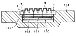
処理容器150内の中央部には、テンプレートTの裏面T2を保持する保持部151が設けられている。保持部151の中央部分は下方に窪み、テンプレートTを収容する収容部152が形成されている。収容部152の下部には、図8に示すようにテンプレートTの外形より僅かに小さい溝部153が形成されている。したがって、収容部152内では、溝部153によってテンプレートTの下面内周部は保持部151と接しておらず、テンプレートTの裏面T2の外周部のみが保持部151に支持されている。収容部152は、図10に示すようにテンプレートTの外形に適合した略四角形の平面形状を有している。収容部152には、側面から内側に突出した突出部154が複数形成され、この突出部154により、収容部152に収容されるテンプレートTの位置決めがされる。また搬送ユニット20の搬送アームから収容部152にテンプレートTを受け渡す際に、当該搬送アームが収容部152と干渉するのを避けるため、収容部152の外周には、切欠き部155が4箇所に形成されている。
溝部153には、図8に示すように紫外線を照射する紫外線照射部160が設けられている。紫外線照射部160は、図11に示すように紫外線を照射するランプ161と、ランプ161を収容するランプハウス162とを有している。ランプ161は、例えば172nmの波長の紫外線を照射する。また、ランプハウス162には、紫外線を透過する材料、例えば石英が用いられる。かかる構成により、紫外線照射部160は、テンプレートTの表面T1に形成された離型膜Sに対して、当該テンプレートTの裏面T2側から紫外線を照射することができる。
保持部151は、図8に示すようにカバー体170に取り付けられ、保持部151の下方には、シャフト171を介して回転駆動部172が設けられている。この回転駆動部172により、保持部151は鉛直周りに所定の速度で回転でき、且つ昇降できる。
保持部151の周囲には、テンプレートTから飛散又は落下する洗浄液と純水を受け止め、回収する回収部としてのカップ180が設けられている。カップ180の下面には、回収した洗浄液と純水を排出する排出管181と、カップ180内の雰囲気を排気する排気管182が接続されている。
図9に示すようにカップ180のX方向負方向(図9の下方向)側には、Y方向(図9の左右方向)に沿って延伸するレール190が形成されている。レール190は、例えばカップ180のY方向負方向(図9の左方向)側の外方からY方向正方向(図9の右方向)側の外方まで形成されている。レール190には、アーム191が取り付けられている。
アーム191には、テンプレートT上に洗浄液と純水を供給するノズル192が支持されている。アーム191は、ノズル駆動部193により、レール190上を移動自在である。これにより、ノズル192は、カップ180のY方向正方向側の外方に設置された待機部194からカップ180内のテンプレートTの中心部上方まで移動できる。また、アーム191は、ノズル駆動部193によって昇降自在であり、ノズル192の高さを調整できる。
ノズル192は、図12及び図13に示すように内管200と、当該内管200の周囲を囲う外管201とを備えた二重管構造を有している。内管200の端部は開口し、洗浄液を供給する洗浄液供給口202を形成している。また、外管201の端部も開口している。そして、内管200と外管201との間の端部は、純水を供給する純水供給口203を形成している。すなわち、純水供給口203は、洗浄液供給口202の周囲に環状に形成されている。
内管200は、洗浄液を供給する洗浄液供給源204に連通している。洗浄液供給源204の内部には、洗浄液、例えばフッ素系溶剤が貯留されている。このフッ素系溶剤は、離型剤の溶剤であって、例えばハイドロフルオロエーテル(HFE:Hydro Fluoro Ether)である。そして、洗浄液供給源204から供給された洗浄液は、内管200の内部を流れて、洗浄液供給口202から供給される。
外管201は、純水を貯留して供給する純水供給源205に連通している。純水は、上記洗浄液と比べて比重が小さく、且つ当該洗浄液と親和性を有しない。そして、純水供給源205から供給された純水は、内管200と外管201との間を流れて、純水供給口203から供給される。
かかる構成により、ノズル192は、テンプレートTの表面T1上の離型膜Sに対して、当該テンプレートTの表面T1側から洗浄液と純水を供給することができる。なお、本実施の形態では、これらノズル192、洗浄液供給源204及び純水供給源205が液供給部を構成している。
処理容器150の外部には、図8に示すようにカップ180で回収された洗浄後の洗浄液と純水を分離する分離部210が設けられている。分離部210は、排液管181に接続されている。
分離部210は、図14に示すように排液管181から排出された洗浄液Fと純水Dを貯留して分離する貯留容器211を有している。貯留容器211の側面には、純水Dを排出するための純水排出管212と、洗浄液Fを排出するための洗浄液排出管213が設けられている。純水排出管212は、洗浄液排出管213の上方に配置されている。そして、貯留容器211の内部では、洗浄液Fと純水Dの比重の違いを利用して、当該洗浄液Fと純水Dを分離する。すなわち、純水Dの比重は洗浄液Fの比重よりも小さいため、純水Dが洗浄液Fの上方に分離される。しかも、純水Dは洗浄液Fと親和性を有しないため、洗浄液Fと適切に分離される。分離された純水Dと洗浄液Fは、それぞれ上述した純水排出管212と洗浄液排出管213から排出される。
また、処理容器150の外部には、図8に示すように分離部210で分離された洗浄液Fを蒸留する蒸留部220が設けられている。蒸留部220は、分離部210の洗浄液排出管213に接続されている。
蒸留部220は、図15に示すように洗浄液排出管213から排出され、不純物である離型膜Sが混在した洗浄液Fを蒸留するものである。蒸留部220は、洗浄液排出管213から排出された洗浄液Fを加熱して気化する気化容器221と、気化容器221で気化した蒸気を冷却して液化する冷却管222と、冷却管222で液化した洗浄液Fを回収する回収容器223とを有している。冷却管222の一端部は気化容器221の上面に接続され、冷却管222の他端部は回収容器223の上面に接続されている。
気化容器221の底面には、洗浄液Fを加熱するヒータ224が設けられている。ヒータ224は、洗浄液Fをその沸点以上の温度で加熱し、洗浄液Fを蒸発させて気化させる。例えば洗浄液Fとしてハイドロフルオロエーテルを用いた場合、その沸点は60℃~130℃である。このとき、洗浄液F中に混在する離型膜Sは気化しない。したがって、洗浄液Fのみが気化される。なお、本実施の形態では、洗浄液Fを加熱して気化させていたが、気化容器221の内部を減圧して洗浄液Fを気化させてもよい。
冷却管222の外周には、冷却媒体、例えば冷却水が流通する冷媒流通管225が設けられている。冷媒流通管225には、当該冷媒流通管225に対して、洗浄液Fの沸点以下の冷却媒体を供給する冷媒供給源(図示せず)が接続されている。そして、冷媒流通管225を流通する冷却媒体によって、冷却管222の内部の蒸気が冷却されて液化される。
冷却管222で液化した洗浄液Fは、回収容器223に流入する。回収容器223の側面には、この蒸留されて不純物を含まない洗浄液Fが回収される回収管226が接続されている。回収管226から回収された洗浄液Fは、例えば洗浄液供給源204に貯留される。そして、当該洗浄液Fは、後洗浄ユニット50においてテンプレートTの表面T1を洗浄するのに再利用される。
なお、後洗浄ユニット51、60、61の構成は、上述した後洗浄ユニット50の構成と同様であるので説明を省略する。
以上のインプリントシステム1には、図1に示すように制御部300が設けられている。制御部300は、例えばコンピュータであり、プログラム格納部(図示せず)を有している。プログラム格納部には、インプリントシステム1における後述するインプリント処理を実行するプログラムが格納されている。なお、このプログラムは、例えばコンピュータ読み取り可能なハードディスク(HD)、フレキシブルディスク(FD)、コンパクトディスク(CD)、マグネットオプティカルデスク(MO)、メモリーカードなどのコンピュータに読み取り可能な記憶媒体に記録されていたものであって、その記憶媒体から制御部300にインストールされたものであってもよい。
本実施の形態にかかるインプリントシステム1は以上のように構成されている。次に、そのインプリントシステム1で行われるインプリント処理について説明する。図16は、このインプリント処理の主な処理フローを示し、図17は、各工程におけるテンプレートTとウェハWの状態を示している。
先ず、テンプレート搬送体12によって、カセット載置台10上のテンプレートカセットCTからテンプレートTが取り出され、処理ステーション3の第3の処理ブロックG3内のトランジションユニット33に搬送される(図16の工程A1)。このとき、テンプレートカセットCT内には、テンプレートTは、転写パターンCが形成された表面T1が上方を向くように収容されており、この状態でテンプレートTはトランジションユニット33に搬送される。
その後、搬送ユニット20によって、テンプレートTは、前洗浄ユニット30に搬送される。前洗浄ユニット30では、例えばテンプレートTの表面T1全面に紫外線が照射される。そして、図17(a)に示すようにテンプレートTの表面T1の有機汚染物やパーティクル等の不純物が除去され、当該表面T1が洗浄される(図16の工程A2)。
その後、搬送ユニット20によって、テンプレートTは塗布ユニット21に搬送される。塗布ユニット21では、例えば回転中のテンプレートTの中心部にノズルから離型剤を供給し、遠心力によりテンプレートT上で離型剤を拡散させる、いわゆるスピン塗布法が行われる。そして、図17(b)に示すようにテンプレートTの表面T1全面に離型剤S0が塗布される(図16の工程A3)。なお、離型剤S0の塗布方法は、上述したスピン塗布法に限定されず、種々の方法を取り得る。例えばテンプレートTの幅方向に延伸し、下面にスリット状の供給口が形成されたノズルを用いてテンプレートT上に離型剤S0を塗布してもよいし、例えば離型剤S0が貯留された浸漬槽にテンプレートTを浸漬させて、テンプレートT上に離型剤S0を塗布してもよい。
その後、搬送ユニット20によって、テンプレートTは加熱ユニット34に搬送される。加熱ユニット34では、テンプレートTが例えば200℃に加熱される。所定時間経過後、図17(c)に示すようにテンプレートT上の離型剤S0が焼成される(図16の工程A4)。
その後、搬送ユニット20によって、テンプレートTは温度調節ユニット211に搬送され、テンプレートTが所定の温度に調節される。
その後、搬送ユニット20によって、テンプレートTはリンスユニット22に搬送される。リンスユニット22では、例えばテンプレートTの表面T1に有機溶剤が供給される。所定時間経過すると、離型剤S0の未反応部のみが剥離し、図17(d)に示すようにテンプレートT上に転写パターンCに沿った離型膜Sが成膜される(図16の工程A5)。なお、離型剤S0の未反応部とは、離型剤S0がテンプレートTの表面T1と化学反応して当該表面T1と吸着する部分以外をいう。また、テンプレートTの表面T1への有機溶剤の供給方法には種々の方法を取り得る。例えば有機溶剤を貯留した浸漬槽にテンプレートTを浸漬させてもよいし、いわゆるスピン塗布法を用いて有機溶剤を供給してもよい。
その後、搬送ユニット20によって、テンプレートTは第4の処理ブロックG4のトランジションユニット43に搬送される。続いて、テンプレートTは、インターフェイスステーション4のテンプレート搬送体71によって、反転ユニット72に搬送されて、テンプレートTの表裏面が反転される。すなわち、テンプレートTの裏面T2が上方に向けられる。その後、テンプレートTは、テンプレート搬送体71によってインプリントユニット5に搬送され、テンプレート保持部120のチャック121に吸着保持される。
このように処理ステーション3においてテンプレートTに所定の処理を行い、インプリントユニット5へテンプレートTを搬送中に、ウェハ搬入出ステーション6では、ウェハ搬送体82により、カセット載置台80上のウェハカセットCWからウェハWが取り出され、アライメントユニット83に搬送される。そして、アライメントユニット83において、ウェハWのノッチ部の位置に基づいて、ウェハWの向きが調整される。その後、ウェハWは、ウェハ搬送体82によってインプリントユニット5に搬送される(図16の工程A6)。なお、ウェハ搬入出ステーション6において、ウェハカセットCW内のウェハWは、その被処理面が上方を向くように収容されており、この状態でウェハWはインプリントユニット5に搬送される。
インプリントユニット5に搬入されたウェハWは、昇降ピン102に受け渡され、ウェハ保持部101上に載置され保持される。続いて、ウェハ保持部101に保持されたウェハWを水平方向の所定の位置に移動させて位置合わせをした後、レジスト液ノズル112をウェハWの径方向に移動させ、図17(e)に示すようにウェハW上にレジスト液を塗布し、塗布膜としてのレジスト膜Rを形成する(図16の工程A7)。このとき、制御部300により、レジスト液ノズル112から供給されるレジスト液の供給タイミングや供給量等が制御される。すなわち、ウェハW上に形成されるレジストパターンにおいて、凸部に対応する部分(テンプレートTの転写パターンCにおける凹部に対応する部分)に塗布されるレジスト液の量は多く、凹部に対応する部分(転写パターンCにおける凸部に対応する部分)に塗布されるレジスト液の量は少なくなるように制御される。このように転写パターンCの開口率に応じてウェハW上にレジスト液が塗布される。
ウェハW上にレジスト膜Rが形成されると、ウェハ保持部101に保持されたウェハWを水平方向の所定の位置に移動させて位置合わせを行うと共に、テンプレート保持部120に保持されたテンプレートTを所定の向きに回転させる。そして、図17(e)の矢印に示すようにテンプレートTをウェハW側に下降させる。テンプレートTは所定の位置まで下降し、テンプレートTの表面T1がウェハW上のレジスト膜Rに押し付けられる。なお、この所定の位置は、ウェハW上に形成されるレジストパターンの高さに基づいて設定される。続いて、光源123から光が照射される。光源123からの光は、図17(f)に示すようにテンプレートTを透過してウェハW上のレジスト膜Rに照射され、これによりレジスト膜Rは光重合する。このようにしてウェハW上のレジスト膜RにテンプレートTの転写パターンCが転写され、レジストパターンPが形成される(図16の工程A8)。
その後、図17(g)に示すようにテンプレートTを上昇させて、ウェハW上にレジストパターンPを形成する。このとき、テンプレートTの表面T1には離型膜Sが成膜されているので、ウェハW上のレジストがテンプレートTの表面T1に付着することはない。その後、ウェハWは、昇降ピン102によりウェハ搬送体82に受け渡され、インプリントユニット5からウェハ搬入出ステーション6に搬送され、ウェハカセットCWに戻される(図16の工程A9)。なお、ウェハW上に形成されたレジストパターンPの凹部には、薄いレジストの残存膜Lが残る場合があるが、例えばインプリントシステム1の外部において、図17(h)に示すように当該残存膜Lを除去してもよい。
以上の工程A6~A9(図16中の点線で囲った部分)を繰り返し行い、一のテンプレートTを用いて、複数のウェハW上にレジストパターンPをそれぞれ形成する。この間、上述した工程A1~A5を繰り返し行い、複数のテンプレートTの表面T1上に離型膜Sを成膜する。離型膜Sが成膜されたテンプレートTは、インターフェイスステーション4のバッファカセット73に保管される。
そして、所定枚数のウェハWに対して工程A6~A9が行われると、ウェハ搬送体261によって、使用済みのテンプレートTがインプリントユニット5から搬出され、反転ユニット72に搬送される(図16の工程A10)。続いて、ウェハ搬送体261によって、バッファカセット73内のテンプレートTがインプリントユニット5に搬送される。こうして、インプリントユニット5内のテンプレートTが交換される。なお、テンプレートTを交換するタイミングは、テンプレートTの劣化等を考慮して設定される。また、ウェハWに異なるパターンPを形成する場合にも、テンプレートTが交換される。例えばテンプレートTを1回使用する度に当該テンプレートTを交換してもよい。また、例えば1枚のウェハW毎にテンプレートTを交換してもよいし、例えば1ロット毎にテンプレートTを交換してもよい。
反転ユニット72に搬送された使用済みのテンプレートTは、その表裏面が反転される。すなわちテンプレートTの表面T1が上方に向けられる。その後、ウェハ搬送体261によって、テンプレートTは第4の処理ブロックG4のトランジションユニット43に搬送される。
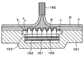
その後、搬送ユニット20によって、テンプレートTは後洗浄ユニット50に搬送され、保持部151に受け渡される。続いて、アーム191によってノズル192をテンプレートTの中心部上方まで移動させると共に、テンプレートTを回転させる。そして、図18に示すように回転中のテンプレートTの表面T1上離型膜Sに対して、ノズル192によりテンプレートTの表面T1側から洗浄液Fと純水Dを供給する。テンプレートT上に供給された洗浄液Fと純水Dは、遠心力によってテンプレートT上を拡散する。このとき、純水Dの比重は洗浄液Fの比重よりも小さいため、洗浄液Fは純水Dの下方に位置する。しかも、純水Dは洗浄液Fと親和性を有しないため、洗浄液Fと純水Dは完全に分離され、テンプレートT上において二層構造を構成できる。また、ノズル192の純水供給口203は洗浄液供給口202の周囲に形成されているため、洗浄液Fは純水Dに囲われてノズル192から供給される。したがって、テンプレートT上において、洗浄液Fは確実に純水Dの下方に位置する。そして、洗浄液Fがノズル192から供給されてからテンプレートT上で拡散する間、当該洗浄液Fは処理容器150内の雰囲気に触れることがない。
このようにテンプレートT上に洗浄液Fと純水Dを供給すると同時に、テンプレートTの表面T1上の離型膜Sに対して、紫外線照射部160によりテンプレートTの裏面T2側から紫外線を照射する。紫外線照射部160からの紫外線は、テンプレートTを透過して離型膜Sに照射される。このように紫外線照射部160からの紫外線の照射とノズル192からの洗浄液F及び純水Dの供給とは、同時に異なる方向から行われる。
かかる場合、紫外線照射部160から照射された紫外線によって、離型膜SとテンプレートTの表面T1との結合が切断される。そして、離型膜Sが表面T1から剥離される。剥離された離型膜Sは、テンプレートT上の洗浄液Fに溶解される。このとき、洗浄液Fは例えば離型膜S(離型剤S0)の溶剤であるため、上記表面T1から剥離された離型膜Sは洗浄液Fに適切に溶解される。こうして、離型膜SはテンプレートTの表面T1から剥離除去される。
所定時間経過後、離型膜SがテンプレートTの表面T1から完全に剥離除去されると、紫外線照射部160からの紫外線の照射を停止すると共に、ノズル192からの洗浄液Fと純水Dの供給を停止する。その後、引き続きテンプレートTを回転させ、当該テンプレートTの表面T1を乾燥させる。こうして、テンプレートTの表面T1が洗浄される(図16の工程A11)。
なお、工程A11において、洗浄後にテンプレートTから飛散又は落下する洗浄液Fと純水Dは、カップ180で回収される。回収された洗浄液Fと純水Dは、分離部210において洗浄液Fと純水Dに分離される。その後、分離された洗浄液Fは、蒸留部220において蒸留され回収される。このとき、分離部210で分離された洗浄液F中には離型膜Sが混在しているが、当該洗浄液Fを蒸留部220で蒸留することによって、不純物を含まない洗浄液Fが回収される。そして、回収された洗浄液Fは、例えば洗浄液供給源204に貯留され、後洗浄ユニット50においてテンプレートTの表面T1を洗浄するのに再利用される。
その後、搬送ユニット20によって、テンプレートTは、検査ユニット52に搬送される。検査ユニット52では、例えば干渉縞の観察等により、テンプレートTの表面T1が検査される(図16の工程A12)。
その後、搬送ユニット20によって、テンプレートTはトランジションユニット33に搬送され、テンプレート搬送体12によってテンプレートカセットCTに戻される。なお、検査ユニット52の検査結果が良好な場合、例えばテンプレートTの表面T1が適切に洗浄され、且つその表面T1が劣化していない場合には、テンプレートカセットCTに戻されたテンプレートTは、インプリントユニット1内で再度使用される。一方、検査ユニット52の検査結果が悪い場合、例えばテンプレートTの表面T1が劣化している場合には、テンプレートTはインプリントユニット1の外部に搬出される。
こうしてインプリントシステム1における一連のインプリント処理が終了し、テンプレートTを連続的に交換しつつ、複数のウェハWに対して所定のレジストパターンPが連続的に形成される。
以上の実施の形態によれば、工程A11において、紫外線の照射と洗浄液F及び純水Dの供給の両方によってテンプレートTの表面T1が洗浄される。すなわち、テンプレートTに対していわゆるドライ洗浄とウェット洗浄の両方が行われるので、テンプレートTの表面T1を短時間で確実に洗浄することができる。
また、工程A11において、テンプレートTの裏面T2側から離型膜Sに紫外線を照射しながら、テンプレートTの表面T1側から離型膜Sに洗浄液Fと純水Dを供給している。すなわち、紫外線の照射と洗浄液F及び純水Dの供給は、同時に異なる方向から行われている。このため、従来のように紫外線が洗浄液中を透過することがなく、当該紫外線が減衰することがない。そうすると、紫外線のエネルギを最大限に生かすことができ、テンプレートT上の離型膜Sに紫外線を適切に照射することができる。したがって、テンプレートTの表面T1の離型膜Sを効率よく除去して、当該テンプレートTの表面T1を効率よく洗浄することができる。
また、工程A11においてテンプレートT上に洗浄液Fと純水Dを供給する際、純水Dの比重は洗浄液Fの比重よりも小さいため、洗浄液Fは純水Dの下方に位置する。しかも、純水Dは洗浄液Fと親和性を有しないため、洗浄液Fと純水Dは完全に分離され、テンプレートT上において二層構造を構成できる。また、ノズル192の純水供給口203は洗浄液供給口202の周囲に形成されているため、洗浄液Fは純水Dに囲われてノズル192から供給される。したがって、テンプレートT上において、洗浄液Fは確実に純水Dの下方に位置する。そして、洗浄液Fがノズル192から供給されてからテンプレートT上で拡散する間、当該洗浄液Fは処理容器150内の雰囲気に触れることがない。ここで洗浄液Fは例えばフッ素系溶剤であるため、大気に触れて気化すると周囲の環境を汚染するおそれがある。この点、本実施の形態では、洗浄液Fは処理容器150内の雰囲気に触れることがないため、当該雰囲気は汚染されない。したがって、本実施の形態は環境対策にも十分に配慮している。
また、工程A11において、洗浄後の洗浄液Fと純水Dが分離部210で分離された後、分離された洗浄液Fが蒸留部220で蒸留される。このように蒸留された洗浄液Fは、後洗浄ユニット50においてテンプレートTの表面T1を洗浄するのに再利用される。したがって、洗浄液Fの使用量を低減することができ、テンプレートTの表面T1を効率よく洗浄することができる。
以上の実施の形態のインプリントシステム1は処理ステーション3を有しているので、インプリントシステム1において、テンプレートT上に離型膜Sを成膜しつつ、当該テンプレートTをインプリントユニット5に連続的に供給できる。これによって、例えばテンプレートTが劣化する前、あるいは複数のウェハW上に異なるレジストパターンPを形成する場合でも、インプリントユニット5内のテンプレートTを連続して効率よく交換することができる。したがって、複数のウェハWに対して所定のレジストパターンPを連続的に形成することができる。また、これによって、半導体デバイスの量産化を実現することも可能となる。
また、処理ステーション3内には、後洗浄ユニット50、51、60、61が設けられているので、インプリントシステム1内で使用済みのテンプレートTの表面T1を洗浄することができる。これによって、インプリントユニット1内でテンプレートTを再度使用することができる。
以上の実施の形態の後洗浄ユニット50は、図19に示すように保持部151に保持されたテンプレートTと紫外線照射部160との間の空間、すなわち溝部153(以下、単に「溝部153」という。)に不活性ガスを供給するガス供給部400を有していてもよい。ガス供給部400は、溝部153に不活性ガスを供給するためのガス供給管401と、ガス供給管401に接続されたガス供給源402とを有している。ガス供給管401は、溝部153において開口し、保持部151の内部を通ってガス供給源402に連通している。また、ガス供給源402の内部には、不活性ガス、例えば窒素ガスが貯留されている。
かかる場合、工程A11において、テンプレートTの表面T1上の離型膜Sに対して、紫外線照射部160から紫外線を照射する際、溝部153内に不活性ガスが供給される。ここで、紫外線は大気中でも減衰する。本実施の形態によれば、紫外線が通過する溝部153内が不活性ガスで充填されているので、大気による紫外線の減衰を抑制することができる。したがって、紫外線のエネルギをさらに生かすことができ、テンプレートTの表面T1をより効率よく洗浄することができる。また、溝部153内が不活性ガスで充填されるので、当該溝部153内に洗浄液Fが流入するのを抑制することができる。したがって、テンプレートTの表面T1をさらに効率よく洗浄することができる。
以上の実施の形態の後洗浄ユニット50、51、60、61では、保持部151は回転自在に構成されていたが、当該保持部151を回転させないようにしてもよい。かかる場合、ノズル192として、テンプレートTの幅方向に延伸し、下面にスリット状の供給口が形成されたノズルを用いてもよい。そして、工程A11において、このノズルをテンプレートTの辺方向に移動させながら、供給口からテンプレートTの表面T1に洗浄液Fと純水Dが供給される。また、後洗浄ユニット50には、例えば窒素等の不活性ガスや乾燥空気などのガスをテンプレートTの表面T1に吹き付けるガスノズルが別途設けられてもよい。そして、工程A11において、前記ガスをテンプレートTの表面T1に吹き付けて、当該表面T1が乾燥される。
また、以上の実施の形態の後洗浄ユニット50、51、60、61では、ノズル192は二重管構造を有し、当該ノズル192から洗浄液Fと純水Dを共に供給していたが、ノズル192に代えて、洗浄液Fを供給するノズルと純水Dを供給するノズルを別々に設けてもよい。
さらに、以上の実施の形態の後洗浄ユニット50、51、60、61は、テンプレートTの表面T1だけでなく裏面T2もさらに洗浄してもよい。また、検査ユニット52、62も、テンプレートTの表面T1だけでなく裏面T2もさらに検査してもよい。
以上、添付図面を参照しながら本発明の好適な実施の形態について説明したが、本発明はかかる例に限定されない。当業者であれば、特許請求の範囲に記載された思想の範疇内において、各種の変更例または修正例に想到し得ることは明らかであり、それらについても当然に本発明の技術的範囲に属するものと了解される。本発明はこの例に限らず種々の態様を採りうるものである。本発明は、基板がウェハ以外のFPD(フラットパネルディスプレイ)、フォトマスク用のマスクレチクルなどの他の基板である場合にも適用できる。
1 インプリントシステム
5 インプリントユニット
50、51、60、61 後洗浄ユニット
151 保持部
153 溝部
160 紫外線照射部
180 カップ
192 ノズル
202 洗浄液供給口
203 純水供給口
204 洗浄液供給源
205 純水供給源
210 分離部
220 蒸留部
300 制御部
400 ガス供給部
C 転写パターン
D 純水
F 洗浄液
P レジストパターン
R レジスト膜
S 離型膜
T テンプレート
T1 表面
T2 裏面
W ウェハ
5 インプリントユニット
50、51、60、61 後洗浄ユニット
151 保持部
153 溝部
160 紫外線照射部
180 カップ
192 ノズル
202 洗浄液供給口
203 純水供給口
204 洗浄液供給源
205 純水供給源
210 分離部
220 蒸留部
300 制御部
400 ガス供給部
C 転写パターン
D 純水
F 洗浄液
P レジストパターン
R レジスト膜
S 離型膜
T テンプレート
T1 表面
T2 裏面
W ウェハ
Claims (14)
- テンプレートの表面の転写パターン上に成膜された離型膜を除去して当該テンプレートの表面を洗浄するテンプレート処理方法であって、
前記テンプレートの表面の離型膜に対して前記テンプレートの裏面側から紫外線を照射しながら、当該離型膜に対して前記テンプレートの表面側から洗浄液を供給して、前記テンプレートの表面を洗浄する。 - 請求項1に記載のテンプレート処理方法において、
前記テンプレートの表面の離型膜に対して、前記洗浄液と比べて比重が小さく、且つ当該洗浄液と親和性を有しない純水を前記洗浄液と共に供給する。 - 請求項2に記載のテンプレート処理方法において、
前記洗浄液と純水は同一のノズルから供給され、
前記ノズルには、前記洗浄液を供給する洗浄液供給口と、前記洗浄液供給口の周囲に環状に形成され、純水を供給する純水供給口とが形成されている。 - 請求項2に記載のテンプレート処理方法において、
前記テンプレートの表面を洗浄した後、洗浄後の前記洗浄液と純水を回収し、
その後、前記回収された洗浄液と純水を分離し、
その後、前記分離された洗浄液を蒸留して当該洗浄液をテンプレートの表面の洗浄に再利用する。 - 請求項1に記載のテンプレート処理方法において、
前記洗浄液は、フッ素系溶剤である。 - 請求項1に記載のテンプレート処理方法において、
前記テンプレートの裏面側から紫外線を照射する際、紫外線を照射する紫外線照射部と前記テンプレートとに間の空間に不活性ガスを供給する。 - テンプレートの表面の転写パターン上に成膜された離型膜を除去して当該テンプレートの表面を洗浄するテンプレート処理方法を、テンプレート処理装置によって実行させるために、当該テンプレート処理装置を制御する制御部のコンピュータ上で動作するプログラムを格納した読み取り可能なコンピュータ記憶媒体であって、
前記処理方法においては、前記テンプレートの表面の離型膜に対して前記テンプレートの裏面側から紫外線を照射しながら、当該離型膜に対して前記テンプレートの表面側から洗浄液を供給して、前記テンプレートの表面を洗浄する。 - テンプレートの表面の転写パターン上に成膜された離型膜を除去して当該テンプレートの表面を洗浄するテンプレート処理装置であって、
前記テンプレートを保持する保持部と、
前記テンプレートの表面の離型膜に対して、当該テンプレートの表面側から洗浄液を供給する液供給部と、
前記テンプレートの表面の離型膜に対して、当該テンプレートの裏面側から紫外線を照射する紫外線照射部と、を有する。 - 請求項8に記載のテンプレート処理装置において、
前記液供給部は、前記テンプレートの表面の離型膜に対して、前記洗浄液と比べて比重が小さく、且つ当該洗浄液と親和性を有しない純水を供給するものである。 - 請求項9に記載のテンプレート処理装置において、
前記液供給部は、前記洗浄液と純水を供給するノズルを有し、
前記ノズルには、前記洗浄液を供給する洗浄液供給口と、前記洗浄液供給口の周囲に環状に形成され、純水を供給する純水供給口とが形成されている。 - 請求項9に記載のテンプレート処理装置において、
洗浄後の前記洗浄液と純水を回収する回収部と、
前記回収された洗浄液と純水を分離する分離部と、
前記分離された洗浄液を蒸留する蒸留部と、を有する。 - 請求項8に記載のテンプレート処理装置において、
前記洗浄液は、フッ素系溶剤である。 - 請求項8に記載のテンプレート処理装置において、
前記紫外線照射部は前記保持部の内部に配置され、
前記保持部に保持されたテンプレートと前記紫外線照射部との間の空間に、不活性ガスを供給するガス供給部を有する。 - テンプレートの表面の転写パターン上に成膜された離型膜を除去して当該テンプレートの表面を洗浄するテンプレート処理装置と、インプリント装置とを備えた、インプリントシステムであって、
前記テンプレート処理装置は、
前記テンプレートを保持する保持部と、
前記テンプレートの表面の離型膜に対して、当該テンプレートの表面側から洗浄液を供給する液供給部と、
前記テンプレートの表面の離型膜に対して、当該テンプレートの裏面側から紫外線を照射する紫外線照射部と、を有し、
前記インプリント装置は、
表面に離型膜が成膜された前記テンプレートを用いて、前記転写パターンを基板上に形成される塗布膜に転写し、当該塗布膜に所定のパターンを形成するものである。
Applications Claiming Priority (2)
| Application Number | Priority Date | Filing Date | Title |
|---|---|---|---|
| JP2011033099A JP5346049B2 (ja) | 2011-02-18 | 2011-02-18 | テンプレート処理方法、プログラム、コンピュータ記憶媒体、テンプレート処理装置及びインプリントシステム |
| JP2011-033099 | 2011-02-18 |
Publications (1)
| Publication Number | Publication Date |
|---|---|
| WO2012111359A1 true WO2012111359A1 (ja) | 2012-08-23 |
Family
ID=46672302
Family Applications (1)
| Application Number | Title | Priority Date | Filing Date |
|---|---|---|---|
| PCT/JP2012/050251 Ceased WO2012111359A1 (ja) | 2011-02-18 | 2012-01-10 | テンプレート処理方法、コンピュータ記憶媒体、テンプレート処理装置及びインプリントシステム |
Country Status (3)
| Country | Link |
|---|---|
| JP (1) | JP5346049B2 (ja) |
| TW (1) | TW201249555A (ja) |
| WO (1) | WO2012111359A1 (ja) |
Cited By (2)
| Publication number | Priority date | Publication date | Assignee | Title |
|---|---|---|---|---|
| JP2021009959A (ja) * | 2019-07-02 | 2021-01-28 | 東京エレクトロン株式会社 | 基板処理装置及び基板処理方法 |
| US11322384B2 (en) * | 2019-09-30 | 2022-05-03 | Shin-Etsu Engineering Co., Ltd. | Substrate processing apparatus and substrate processing method |
Families Citing this family (5)
| Publication number | Priority date | Publication date | Assignee | Title |
|---|---|---|---|---|
| JP6618334B2 (ja) | 2015-06-03 | 2019-12-11 | 株式会社Screenホールディングス | 基板処理装置、膜形成ユニット、基板処理方法および膜形成方法 |
| WO2016194285A1 (ja) | 2015-06-03 | 2016-12-08 | 株式会社Screenホールディングス | 基板処理装置、膜形成ユニット、基板処理方法および膜形成方法 |
| JP6603487B2 (ja) * | 2015-06-22 | 2019-11-06 | 株式会社Screenホールディングス | 基板処理装置および基板処理方法 |
| JP7652645B2 (ja) * | 2021-06-30 | 2025-03-27 | キヤノン株式会社 | 平坦化装置、および物品製造方法 |
| CN118142951B (zh) * | 2024-05-08 | 2024-07-02 | 江苏金纬智能制造有限公司 | 用于锂电池隔膜铸片的成型装置 |
Citations (5)
| Publication number | Priority date | Publication date | Assignee | Title |
|---|---|---|---|---|
| JP2010046923A (ja) * | 2008-08-21 | 2010-03-04 | Toshiba Corp | テンプレートの洗浄方法及びパターン形成方法 |
| JP2011000806A (ja) * | 2009-06-19 | 2011-01-06 | Tokyo Electron Ltd | インプリントシステム、インプリント方法、プログラム及びコンピュータ記憶媒体 |
| JP2011009362A (ja) * | 2009-06-24 | 2011-01-13 | Tokyo Electron Ltd | インプリントシステム、インプリント方法、プログラム及びコンピュータ記憶媒体 |
| JP2011005695A (ja) * | 2009-06-24 | 2011-01-13 | Tokyo Electron Ltd | テンプレート処理装置、インプリントシステム、離型剤処理方法、プログラム及びコンピュータ記憶媒体 |
| JP2011005696A (ja) * | 2009-06-24 | 2011-01-13 | Tokyo Electron Ltd | テンプレート処理装置、インプリントシステム、離型剤処理方法、プログラム及びコンピュータ記憶媒体 |
Family Cites Families (2)
| Publication number | Priority date | Publication date | Assignee | Title |
|---|---|---|---|---|
| JP2012009831A (ja) * | 2010-05-21 | 2012-01-12 | Tokyo Electron Ltd | インプリントシステム、インプリント方法、プログラム及びコンピュータ記憶媒体 |
| JP5411201B2 (ja) * | 2010-05-21 | 2014-02-12 | 東京エレクトロン株式会社 | インプリントシステム、インプリント方法、プログラム及びコンピュータ記憶媒体 |
-
2011
- 2011-02-18 JP JP2011033099A patent/JP5346049B2/ja not_active Expired - Fee Related
-
2012
- 2012-01-10 WO PCT/JP2012/050251 patent/WO2012111359A1/ja not_active Ceased
- 2012-02-17 TW TW101105248A patent/TW201249555A/zh unknown
Patent Citations (5)
| Publication number | Priority date | Publication date | Assignee | Title |
|---|---|---|---|---|
| JP2010046923A (ja) * | 2008-08-21 | 2010-03-04 | Toshiba Corp | テンプレートの洗浄方法及びパターン形成方法 |
| JP2011000806A (ja) * | 2009-06-19 | 2011-01-06 | Tokyo Electron Ltd | インプリントシステム、インプリント方法、プログラム及びコンピュータ記憶媒体 |
| JP2011009362A (ja) * | 2009-06-24 | 2011-01-13 | Tokyo Electron Ltd | インプリントシステム、インプリント方法、プログラム及びコンピュータ記憶媒体 |
| JP2011005695A (ja) * | 2009-06-24 | 2011-01-13 | Tokyo Electron Ltd | テンプレート処理装置、インプリントシステム、離型剤処理方法、プログラム及びコンピュータ記憶媒体 |
| JP2011005696A (ja) * | 2009-06-24 | 2011-01-13 | Tokyo Electron Ltd | テンプレート処理装置、インプリントシステム、離型剤処理方法、プログラム及びコンピュータ記憶媒体 |
Cited By (3)
| Publication number | Priority date | Publication date | Assignee | Title |
|---|---|---|---|---|
| JP2021009959A (ja) * | 2019-07-02 | 2021-01-28 | 東京エレクトロン株式会社 | 基板処理装置及び基板処理方法 |
| JP7308087B2 (ja) | 2019-07-02 | 2023-07-13 | 東京エレクトロン株式会社 | 基板処理装置及び基板処理方法 |
| US11322384B2 (en) * | 2019-09-30 | 2022-05-03 | Shin-Etsu Engineering Co., Ltd. | Substrate processing apparatus and substrate processing method |
Also Published As
| Publication number | Publication date |
|---|---|
| JP5346049B2 (ja) | 2013-11-20 |
| JP2012174768A (ja) | 2012-09-10 |
| TW201249555A (en) | 2012-12-16 |
Similar Documents
| Publication | Publication Date | Title |
|---|---|---|
| JP5443070B2 (ja) | インプリントシステム | |
| JP5346049B2 (ja) | テンプレート処理方法、プログラム、コンピュータ記憶媒体、テンプレート処理装置及びインプリントシステム | |
| JP5060517B2 (ja) | インプリントシステム | |
| WO2010150741A1 (ja) | インプリントシステム、インプリント方法及びコンピュータ記憶媒体 | |
| JP7010299B2 (ja) | マスクパターン形成方法、記憶媒体及び基板処理装置 | |
| JP2012009831A (ja) | インプリントシステム、インプリント方法、プログラム及びコンピュータ記憶媒体 | |
| JP2017147329A (ja) | 基板処理装置および基板処理方法 | |
| JP5411201B2 (ja) | インプリントシステム、インプリント方法、プログラム及びコンピュータ記憶媒体 | |
| JP2011104910A (ja) | テンプレート処理方法、プログラム、コンピュータ記憶媒体、テンプレート処理装置及びインプリントシステム | |
| US8031324B2 (en) | Substrate processing apparatus with integrated cleaning unit | |
| JP6603487B2 (ja) | 基板処理装置および基板処理方法 | |
| JP2011192868A (ja) | テンプレート処理方法、プログラム、コンピュータ記憶媒体及びテンプレート処理装置 | |
| JP5285515B2 (ja) | テンプレート処理装置、インプリントシステム、離型剤処理方法、プログラム及びコンピュータ記憶媒体 | |
| JP2013098477A (ja) | 基板処理システム、基板搬送方法、プログラム及びコンピュータ記憶媒体 | |
| JP5149244B2 (ja) | インプリントシステム、インプリント方法、プログラム及びコンピュータ記憶媒体 | |
| JP5231366B2 (ja) | テンプレート処理方法、プログラム、コンピュータ記憶媒、テンプレート処理装置及びインプリントシステム | |
| JP5285514B2 (ja) | テンプレート処理装置、インプリントシステム、離型剤処理方法、プログラム及びコンピュータ記憶媒体 | |
| JP5355615B2 (ja) | 基板処理方法、プログラム、コンピュータ記憶媒体、基板処理装置及びインプリントシステム | |
| JP5108834B2 (ja) | テンプレート処理装置、インプリントシステム、離型剤処理方法、プログラム及びコンピュータ記憶媒体 | |
| WO2012060205A1 (ja) | テンプレート処理方法、コンピュータ記憶媒体及びテンプレート処理装置 | |
| JP5487064B2 (ja) | テンプレート処理方法、プログラム、コンピュータ記憶媒体、テンプレート処理装置及びインプリントシステム |
Legal Events
| Date | Code | Title | Description |
|---|---|---|---|
| 121 | Ep: the epo has been informed by wipo that ep was designated in this application |
Ref document number: 12747628 Country of ref document: EP Kind code of ref document: A1 |
|
| NENP | Non-entry into the national phase |
Ref country code: DE |
|
| 122 | Ep: pct application non-entry in european phase |
Ref document number: 12747628 Country of ref document: EP Kind code of ref document: A1 |