WO2012111210A1 - 胴部幅測定装置および体脂肪測定装置 - Google Patents
胴部幅測定装置および体脂肪測定装置 Download PDFInfo
- Publication number
- WO2012111210A1 WO2012111210A1 PCT/JP2011/076929 JP2011076929W WO2012111210A1 WO 2012111210 A1 WO2012111210 A1 WO 2012111210A1 JP 2011076929 W JP2011076929 W JP 2011076929W WO 2012111210 A1 WO2012111210 A1 WO 2012111210A1
- Authority
- WO
- WIPO (PCT)
- Prior art keywords
- subject
- torso
- trunk
- width
- information
- Prior art date
- Legal status (The legal status is an assumption and is not a legal conclusion. Google has not performed a legal analysis and makes no representation as to the accuracy of the status listed.)
- Ceased
Links
Images

Classifications
-
- G—PHYSICS
- G01—MEASURING; TESTING
- G01B—MEASURING LENGTH, THICKNESS OR SIMILAR LINEAR DIMENSIONS; MEASURING ANGLES; MEASURING AREAS; MEASURING IRREGULARITIES OF SURFACES OR CONTOURS
- G01B5/00—Measuring arrangements characterised by the use of mechanical techniques
- G01B5/02—Measuring arrangements characterised by the use of mechanical techniques for measuring length, width or thickness
-
- A—HUMAN NECESSITIES
- A61—MEDICAL OR VETERINARY SCIENCE; HYGIENE
- A61B—DIAGNOSIS; SURGERY; IDENTIFICATION
- A61B5/00—Measuring for diagnostic purposes; Identification of persons
- A61B5/05—Detecting, measuring or recording for diagnosis by means of electric currents or magnetic fields; Measuring using microwaves or radio waves
- A61B5/053—Measuring electrical impedance or conductance of a portion of the body
- A61B5/0537—Measuring body composition by impedance, e.g. tissue hydration or fat content
-
- A—HUMAN NECESSITIES
- A61—MEDICAL OR VETERINARY SCIENCE; HYGIENE
- A61B—DIAGNOSIS; SURGERY; IDENTIFICATION
- A61B5/00—Measuring for diagnostic purposes; Identification of persons
- A61B5/103—Measuring devices for testing the shape, pattern, colour, size or movement of the body or parts thereof, for diagnostic purposes
- A61B5/107—Measuring physical dimensions, e.g. size of the entire body or parts thereof
- A61B5/1075—Measuring physical dimensions, e.g. size of the entire body or parts thereof for measuring dimensions by non-invasive methods, e.g. for determining thickness of tissue layer
-
- A—HUMAN NECESSITIES
- A61—MEDICAL OR VETERINARY SCIENCE; HYGIENE
- A61B—DIAGNOSIS; SURGERY; IDENTIFICATION
- A61B5/00—Measuring for diagnostic purposes; Identification of persons
- A61B5/103—Measuring devices for testing the shape, pattern, colour, size or movement of the body or parts thereof, for diagnostic purposes
- A61B5/107—Measuring physical dimensions, e.g. size of the entire body or parts thereof
- A61B5/1079—Measuring physical dimensions, e.g. size of the entire body or parts thereof using optical or photographic means
-
- A—HUMAN NECESSITIES
- A61—MEDICAL OR VETERINARY SCIENCE; HYGIENE
- A61B—DIAGNOSIS; SURGERY; IDENTIFICATION
- A61B5/00—Measuring for diagnostic purposes; Identification of persons
- A61B5/48—Other medical applications
- A61B5/4869—Determining body composition
- A61B5/4872—Body fat
-
- G—PHYSICS
- G01—MEASURING; TESTING
- G01B—MEASURING LENGTH, THICKNESS OR SIMILAR LINEAR DIMENSIONS; MEASURING ANGLES; MEASURING AREAS; MEASURING IRREGULARITIES OF SURFACES OR CONTOURS
- G01B11/00—Measuring arrangements characterised by the use of optical techniques
- G01B11/02—Measuring arrangements characterised by the use of optical techniques for measuring length, width or thickness
- G01B11/04—Measuring arrangements characterised by the use of optical techniques for measuring length, width or thickness specially adapted for measuring length or width of objects while moving
- G01B11/043—Measuring arrangements characterised by the use of optical techniques for measuring length, width or thickness specially adapted for measuring length or width of objects while moving for measuring length
-
- A—HUMAN NECESSITIES
- A61—MEDICAL OR VETERINARY SCIENCE; HYGIENE
- A61B—DIAGNOSIS; SURGERY; IDENTIFICATION
- A61B5/00—Measuring for diagnostic purposes; Identification of persons
- A61B5/68—Arrangements of detecting, measuring or recording means, e.g. sensors, in relation to patient
- A61B5/6801—Arrangements of detecting, measuring or recording means, e.g. sensors, in relation to patient specially adapted to be attached to or worn on the body surface
- A61B5/6813—Specially adapted to be attached to a specific body part
- A61B5/6823—Trunk, e.g., chest, back, abdomen, hip
-
- A—HUMAN NECESSITIES
- A61—MEDICAL OR VETERINARY SCIENCE; HYGIENE
- A61B—DIAGNOSIS; SURGERY; IDENTIFICATION
- A61B5/00—Measuring for diagnostic purposes; Identification of persons
- A61B5/68—Arrangements of detecting, measuring or recording means, e.g. sensors, in relation to patient
- A61B5/6801—Arrangements of detecting, measuring or recording means, e.g. sensors, in relation to patient specially adapted to be attached to or worn on the body surface
- A61B5/6813—Specially adapted to be attached to a specific body part
- A61B5/6825—Hand
-
- A—HUMAN NECESSITIES
- A61—MEDICAL OR VETERINARY SCIENCE; HYGIENE
- A61B—DIAGNOSIS; SURGERY; IDENTIFICATION
- A61B5/00—Measuring for diagnostic purposes; Identification of persons
- A61B5/68—Arrangements of detecting, measuring or recording means, e.g. sensors, in relation to patient
- A61B5/6801—Arrangements of detecting, measuring or recording means, e.g. sensors, in relation to patient specially adapted to be attached to or worn on the body surface
- A61B5/6813—Specially adapted to be attached to a specific body part
- A61B5/6829—Foot or ankle
Definitions
- the present invention relates to a torso width measuring device for measuring the torso width and torso length of a subject and a body fat measuring device using the torso width measuring device.
- visceral fat mass is attracting attention as an index for determining whether or not it is visceral fat type obesity.
- This visceral fat-type obesity is said to induce lifestyle-related diseases that easily cause arteriosclerosis such as diabetes, hypertension, and hyperlipidemia, and utilization of the above index is expected from the viewpoint of prevention of these diseases.
- the visceral fat is fat accumulated around the viscera inside the abdominal muscles and back muscles, and is distinguished from subcutaneous fat located on the surface layer of the trunk.
- a visceral fat cross-sectional area an area occupied by visceral fat (hereinafter referred to as a visceral fat cross-sectional area) in a torso section corresponding to the umbilicus position.
- the bioimpedance method is a method for measuring the amount of body fat widely used in home body fat measuring devices. It is measured by placing electrodes in contact with the extremities and measuring the bioimpedance using these electrodes. The body fat mass is calculated from the bioimpedance.
- the above-described body fat measurement device can accurately measure the accumulation degree of body fat for each part of the body such as the whole body, limbs, and torso.
- the body fat mass is calculated by measuring the body size of the subject such as the width of the trunk and the length of the trunk. It is required to be used in the arithmetic processing for.
- JP-A-2005-288023 Patent Document 1
- JP-A-2008-23232 Patent Document 2
- JP-A-2008-237571 Patent Document 3
- JP-A-2009-22482 Patent Document 4
- JP-A-2010-69250 Patent Document 5
- Each of the measuring devices for measuring the physique of the subject disclosed in each of the above documents is a large-scale device that surrounds the periphery of the subject's torso, and is widely used for installing and storing the measuring device when used at home. Space is required.
- the cost of the measuring apparatus will increase.
- the present invention has been made to solve the above-described problems, has a simple structure without increasing in size, and further has a configuration capable of suppressing an increase in cost. It is an object of the present invention to provide a trunk width measuring device and a body fat measuring device using the trunk width measuring device.
- the torso width measuring device of the present invention is a torso width measuring device for measuring a torso width and a torso width of a subject in a supine position, and is disposed on a side surface of the torso of the subject.
- a support bar a measurement bar that is supported so as to be pivotable in the vertical direction around the first support point with respect to the support column, and extends above the torso of the subject, and is positioned above the torso of the subject
- a distance sensor that is held by the measurement bar and that is rotatably held around the second support point so as to hang down in the direction of gravity, and is provided at at least one of the first support point and the second support point
- An angle sensor, and a control unit that processes inclination angle information with respect to the vertical direction of the measurement bar obtained from the angle sensor and information obtained from the distance sensor.
- control unit based on the distance information obtained based on the information from the distance sensor and the tilt angle information with respect to the vertical direction of the measurement bar obtained from the angle sensor, the width of the trunk and the trunk of the subject The vertical width is measured.
- the light sensor further includes a light reflecting portion arranged at the umbilicus position of the subject, a contact detecting portion provided on the support column and detecting contact with the trunk portion, and using the optical sensor as the distance sensor.
- the control unit obtains contact information with the torso from the contact detection unit, and light emitted from the photosensor
- the distance information between the light sensor and the light reflecting portion obtained based on information from the light sensor and the angle sensor are obtained. Based on the inclination angle information with respect to the vertical direction of the measurement bar, the body width and the body length of the subject are measured.
- a contact portion is disposed on one side surface of the torso of the subject, and the contact detection unit transmits information on current flow to the control unit when the contact portion is in contact with the contact detection unit. In a state where the contact portion does not contact the contact detection portion, information indicating that no current flows is sent to the control portion.
- the light reflecting portion and the contact portion are provided on a belt member attached around the torso of the subject.
- it has the grip part which the above-mentioned subject holds on the opposite side to the side where the above-mentioned photosensor is provided across the 1st support point of the above-mentioned measurement bar, and is near the above-mentioned grip part
- a measurement start switch for sending a signal for starting measurement by the trunk width measuring device to the control unit is provided.
- the body fat measurement device includes any of the above-described trunk width measurement devices.
- the trunk width measuring device and the trunk width measuring device having a simple structure and a structure capable of suppressing an increase in cost are used without increasing the size. It is possible to provide a body fat measuring device.
- the “torso” is a portion excluding the head, neck and limbs of the body, and corresponds to a so-called trunk.
- “Back” means a portion of the torso located on the back side, and corresponds to a portion of the torso excluding the abdominal portion and the chest portion.
- “Back surface” means the entire body surface of the back, and refers to the entire surface of the trunk that is visible when the subject is observed from the back side.
- the “body axis” refers to an axis positioned along the extending direction of the torso, that is, an axis extending in a direction substantially perpendicular to the cross section of the torso of the subject.
- FIG. 1 (A) and FIG. 1 (B) are diagrams for explaining the measurement principle of the body fat measurement device according to the embodiment of the present invention.
- FIG. 1 (A) is a diagram showing the electrode arrangement when obtaining the bioimpedance of the entire trunk part
- FIG. 1 (B) shows the bioimpedance of the surface layer part on the back side of the trunk part. It is the figure which showed electrode arrangement
- Electrodes EIa A1 and EIa A2 are respectively attached to the surface of the left hand and the surface of the right hand of the subject in order to obtain the bioelectrical impedance of the entire torso. Electrodes EIb A1 and EIb A2 are also attached to the surface of the left foot and the surface of the right foot of the subject, respectively. Then, four pairs of electrodes arranged along the body axis direction are attached to the back surface of the subject along the lateral width direction of the trunk.
- a total of eight electrodes EVa A1 , EVb A1 , EVa A2 , EVb A2 , EVa A3 , EVb A3 , EVa A4 , EVb A4 are attached to the back surface of the subject.
- a constant current I A passing through the torso is applied to the subject using the electrodes EIa A1 , EIa A2 , EIb A1 , and EIb A2 attached to both hands and both feet.
- a potential difference V A1 is detected using a pair of electrodes EVa A1 and EVb A1 attached to the back surface, and a pair of electrodes EVa A2 attached to the back surface.
- the potential difference V A2 is detected using EVb A2
- the potential difference V A3 is detected using a pair of electrodes EVa A3, EVb A3 attached to the back surface, a pair of electrodes attached to the back surface EVa A4, EVb A4 Is used to detect the potential difference V A4 .
- the bioimpedance Zt of the entire trunk is calculated. At this time, if the bioelectrical impedance Zt is obtained by calculating the average value of the detected four potential differences V A1 , V A2 , V A3 , V A4 , the dispersion of fat distribution inside the trunk portion. The influence of can be reduced.
- the bioimpedance Zt calculated from the potential differences V A1 , V A2 , V A3 , and V A4 measured using such a constant current I A is defatting (internal organs, muscles, and skeleton) in the trunk. The place affected by the amount of increases. Therefore, the area occupied by lean body (hereinafter referred to as the lean body sectional area) Sa in the trunk section of the portion corresponding to the umbilicus position can be estimated based on the bioelectrical impedance Zt.
- the four electrodes are attached along the lateral width direction of the body portion. That is, a total of eight electrodes EIa B1 , EIb B1 , EVa B1 , EVb B1 , EVa B2 , EVb B2 , EIa B2 , and EIb B2 are attached to the back surface of the subject as shown in the figure.
- the bioimpedance Zs of the surface layer portion on the back side of the trunk is calculated.
- the bioelectrical impedance Zs is obtained by calculating the average value of the detected two potential differences V B1 and V B2 , the influence of the variation in fat distribution in the surface layer portion of the back part of the torso, etc. Can be reduced.
- the electrodes are switched at four locations. It is also possible to measure the potential difference. By doing in this way, influences, such as a variation in subcutaneous fat, can be reduced further.
- the bioimpedance Zs calculated from the potential differences V B1 and V B2 measured using such constant currents I B1 and I B2 is greatly affected by the subcutaneous fat mass. Therefore, the subcutaneous fat cross-sectional area (hereinafter referred to as the subcutaneous fat cross-sectional area) Sb in the cross section including the umbilical position of the trunk can be estimated based on the bioelectrical impedance Zs.
- the visceral fat cross-sectional area Sx is the torso cross-sectional area St and the above-described lean body cross-sectional area. It can be calculated from the following equation (1) using Sa and the subcutaneous fat cross-sectional area Sb.
- the trunk cross-sectional area St can be calculated by using the trunk circumference (so-called waist length) and the horizontal and vertical widths of the trunk.
- the trunk cross-sectional area St is calculated from the horizontal width and the vertical width of the trunk, if the horizontal width of the trunk is 2 ⁇ a and the vertical width of the trunk is 2 ⁇ b, the cross-sectional shape of the trunk is Since it is approximately elliptical, the trunk section area St can be approximated by the following equation (2).
- the coefficient ⁇ multiplied for the correction is preferably optimized as appropriate according to information such as the subject's sex, age, height, weight, etc. (hereinafter collectively referred to as subject information). That is, the trunk cross-sectional area St can be approximated with higher accuracy by changing the value of the coefficient ⁇ in accordance with the subject information.
- the lean body sectional area Sa can be calculated based on the bioimpedance Zt of the entire trunk.
- the lean body sectional area Sa cannot be accurately calculated only by the bioimpedance Zt of the entire trunk. That is, the lean body sectional area Sa tends to be proportional to the size of the trunk, and in order to calculate the lean body sectional area Sa, it is necessary to further convert the value obtained from the bioimpedance Zt. Therefore, the lean body sectional area Sa is expressed by the following equation (4), for example.
- the value a is a half value of the width of the body part, and is a value related to the size of the body part.
- the value related to the size of the trunk is not limited to the above-mentioned a.
- a ⁇ b may be used so that the horizontal and vertical widths of the trunk are reflected. You may use and a trunk
- drum circumference may be used.
- ⁇ is a coefficient for converting the bioelectrical impedance Zt of the entire trunk part into the lean body sectional area Sa, and is based on, for example, a large number of X-ray CT image samples as in the case where the coefficient ⁇ is obtained.
- the coefficient ⁇ described above is preferably optimized as appropriate according to the subject information, as in the case of the coefficient ⁇ . That is, by changing the value of the coefficient ⁇ according to the subject information, the lean body area Sa can be approximated with higher accuracy.
- the subcutaneous fat cross-sectional area Sb can be calculated based on the bioimpedance Zs of the surface layer portion on the back side of the trunk.
- the subcutaneous fat cross-sectional area Sb cannot be accurately calculated only by the bioimpedance Zs of the surface layer portion on the back side of the trunk. That is, the subcutaneous fat cross-sectional area Sb tends to be proportional to the size of the trunk, and in order to calculate the subcutaneous fat cross-sectional area Sb, it is necessary to further convert the value obtained from the bioelectrical impedance Zs. Therefore, the subcutaneous fat cross-sectional area Sb is expressed by, for example, the following formula (5).
- the value a is a half value of the width of the body part, and is a value related to the size of the body part.
- the value related to the size of the trunk is not limited to the above-mentioned a.
- a ⁇ b may be used so that the horizontal and vertical widths of the trunk are reflected. You may use and a trunk
- drum circumference may be used.
- ⁇ is a coefficient for converting the bioimpedance Zs of the surface layer portion on the back side of the torso to the subcutaneous fat cross-sectional area Sb.
- ⁇ or ⁇ is obtained, The optimum value can be obtained based on a large number of X-ray CT image samples.
- the coefficient ⁇ described above is preferably optimized as appropriate according to the subject information, as in the case of the coefficient ⁇ and the coefficient ⁇ . That is, by changing the value of the coefficient ⁇ according to the subject information, the subcutaneous fat cross-sectional area Sb can be approximated with higher accuracy.
- the torso sectional area St the lean body sectional area Sa calculated based on the bioimpedance Zt of the entire torso, and the back part of the torso
- the visceral fat cross-sectional area Sx is calculated based on the above formula (1), and more specifically, in the above formula (1)
- the visceral fat cross-sectional area Sx is calculated based on the following formula (6) obtained by substituting the formula (3) to the formula (5).
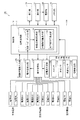
- FIG. 2 is a diagram showing a functional block configuration of the body fat measurement device according to the present embodiment. Next, the configuration of functional blocks of the body fat measurement device according to the present embodiment will be described with reference to FIG.
- the body fat measurement device 1A includes a control unit 10, a constant current generation unit 21, a terminal switching unit 22, a potential difference detection unit 23, a subject information input unit 25, Torso width measurement unit 100, display unit 26, operation unit 27, power supply unit 28, memory unit 29, and a plurality of electrodes HR, HL, BU1 to BU4, BL1 to BL4 attached to the body of the subject. It mainly includes FR and FL.
- the control unit 10 includes an arithmetic processing unit 11, and the arithmetic processing unit 11 includes a bioimpedance measurement unit 12 and a body composition information acquisition unit 14.
- the body width measuring unit 100 measures the body width 2 ⁇ a and the body length 2 ⁇ b, and includes a measurement start switch 150 for starting measurement, an optical sensor 103, angle sensors S1, S2, and By obtaining information from the contact detector 140, the body width 2 ⁇ a and the body length 2 ⁇ b are measured.
- the device configuration will be described later.
- the control unit 10 is configured by, for example, a CPU (Central Processor Unit), and is a part for controlling the entire body fat measurement device 1A. Specifically, the control unit 10 outputs a command to each functional block described above, receives input of various information from each functional block described above, and performs various arithmetic processes based on the received various information. Or Of these, the various arithmetic processes are performed by the arithmetic processing unit 11 provided in the control unit 10 described above.
- a CPU Central Processor Unit
- the plurality of electrodes described above include hand electrodes HR and HL as upper limb electrodes arranged in contact with the surface of the upper limb of the subject, and back electrodes BU1 to BU4 and BL1 to BL4 arranged in contact with the back surface of the subject. And foot electrodes FR and FL as lower limb electrodes arranged in contact with the surface of the lower limbs of the subject.
- the hand electrodes HR and HL are arranged in contact with the subject's palm
- the foot electrodes FR and FL are arranged in contact with the sole of the subject's foot. Further, as shown in FIGS.
- the back electrodes BU1 to BU4 and BL1 to BL4 are arranged in contact with each other in a state of being aligned with the back surface of the subject.
- the hand electrodes HR and HL, the back electrodes BU1 to BU4, BL1 to BL4, and the foot electrodes FR and FL are all electrically connected to the terminal switching unit 22 described above.
- the terminal switching unit 22 is configured by, for example, a relay circuit, and electrically connects a specific electrode selected from the plurality of electrodes described above and the constant current generation unit 21 based on a command input from the control unit 10.
- a specific electrode selected from the plurality of electrodes described above and the potential difference detection unit 23 are electrically connected.
- the electrode electrically connected to the constant current generating unit 21 by the terminal switching unit 22 functions as a constant current application electrode, and is electrically connected to the potential difference detecting unit 23 by the terminal switching unit 22.
- the electrode functions as a potential difference detection electrode.
- each of the plurality of electrodes HR, HL, BU1 to BU4, BL1 to BL4, FR, FL described above is shown in FIG.
- the constant current generation unit 21 generates a constant current based on a command input from the control unit 10 and supplies the generated constant current to the above-described constant current application electrode via the terminal switching unit 22.
- a high-frequency current for example, 50 kHz, 500 ⁇ A
- a constant current is applied to the subject via the constant current application electrode.
- the potential difference detection unit 23 detects a potential difference between electrodes (that is, potential difference detection electrodes) electrically connected to the potential difference detection unit 23 by the terminal switching unit 22 and outputs the detected potential difference to the control unit 10. Thereby, the potential difference between the potential difference detection electrodes in a state where the above-described constant current is applied to the subject is detected.
- Various information obtained from the torso width measurement unit 100 is sent to the control unit 10 and processed by the control unit 10 to calculate the torso width 2 ⁇ a and the torso length 2 ⁇ b, and the body composition
- the information is output to the information acquisition unit 14.
- the subject information input unit 25 is a part for obtaining information about the subject used in the arithmetic processing performed by the arithmetic processing unit 11, and is configured by, for example, a key that can be pressed by the subject.
- the subject information includes at least one of information such as the sex, age, height, and weight of the subject as described above.
- the subject information input unit 25 receives input of subject information and outputs the received subject information to the control unit 10.
- the subject information input unit 25 is not necessarily an essential configuration in light of the present invention, and depends on whether or not it is necessary to use the subject information in the arithmetic processing performed by the arithmetic processing unit 11. The presence or absence is determined.
- the arithmetic processing unit 11 includes the bioelectrical impedance measurement unit 12, the body shape information measurement unit 13, and the body composition information acquisition unit 14 as described above.
- the body composition information acquisition unit 14 includes a visceral fat mass calculation unit 14a and a subcutaneous fat mass calculation unit 14b.
- the bioelectrical impedance measurement unit 12 calculates bioelectrical impedance based on the signal input from the potential difference detection unit 23 and outputs this to the body composition information acquisition unit 14.
- the body composition information acquisition unit 14 receives the bioelectrical impedance input from the bioelectrical impedance measurement unit 12, the horizontal and vertical widths of the torso obtained from the torso width measurement unit 100, and, in some cases, in addition to this, subject information Body composition information is calculated and acquired based on the subject information input from the input unit 25. More specifically, the visceral fat mass calculation unit 14a calculates the visceral fat mass, and the subcutaneous fat mass calculation unit 14b calculates the subcutaneous fat mass.
- the display unit 26 is configured by, for example, an LCD (Liquid Crystal Display) or the like, and displays the body composition information calculated by the body composition information acquisition unit 14 described above. More specifically, the visceral fat mass calculated by the visceral fat mass calculation unit 14a and the subcutaneous fat mass calculated by the subcutaneous fat mass calculation unit 14b are based on the signal output from the control unit 10 and the display unit 26. Is displayed.
- the visceral fat mass is displayed, for example, as a visceral fat cross-sectional area
- the subcutaneous fat mass is displayed, for example, as a subcutaneous fat cross-sectional area.
- the operation unit 27 is a part for the subject to input a command to the body fat measurement device 1A, and is configured by, for example, a button that can be pressed by the subject.
- the operation unit 27 includes various operation buttons such as a power button and a measurement button.
- the power supply unit 28 is a part for supplying power to the control unit 10, and an internal power source such as a battery or an external power source such as a commercial power source is used.
- the memory unit 29 is configured by, for example, a RAM (Random Access Memory), a ROM (Read Only Memory), or the like, and is a part for storing various data, programs, and the like related to the body fat measurement device 1A.
- the memory unit 29 stores, for example, the above-described subject information, calculated body composition information, a body composition information measurement program for performing a body composition information measurement process described later, and the like.
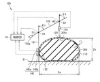
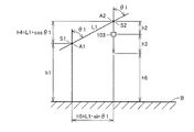
- FIG. 3 is a cross-sectional view illustrating a schematic configuration of the body width measuring device 100
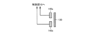
- FIG. 4 is a cross-sectional view illustrating a detailed structure of the contact detection unit 140 and the contact portion 130 employed in the body width measuring device 100
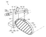
- FIG. 5 is a perspective view showing a specific configuration of the trunk width measuring apparatus 100
- FIG. 6 is a schematic diagram showing a measurement method of the trunk width measuring apparatus 100.
- this torso width measuring apparatus 100 is a torso width measuring apparatus for measuring a torso lateral width 2 ⁇ a and a torso vertical width 2 ⁇ b of a subject in a supine position. is there.
- the light reflecting portion 120 disposed at the position of the subject's umbilicus 305n, the contact portion 130 disposed on one side surface (the right flank in the drawing) of the subject's torso 305, and the side surface of the subject's torso 305
- a support column 101 that is arranged and has a contact detection unit 140 that detects contact with the contact unit 130 and that extends in the vertical direction, and is supported by the support column 101 so as to be rotatable in the vertical direction around the first support point A1.
- the optical sensor 103 is provided. In the present embodiment, the case where the first support point A1 is positioned vertically above the contact detection unit 140 is illustrated, but the present invention is not limited to this configuration.
- a grip 102g held by the subject is provided on the other end side opposite to the one end side where the optical sensor 103 is provided across the first support point A1 of the measurement bar 102.
- the grip may be provided with hand electrodes HR and HL.
- the measurement bar 102 in the vicinity of the grip 102g is provided with a measurement start switch 150 that sends a signal for starting measurement by the body width measuring device 100 to the control unit 10.
- the measurement start switch 150 is not necessarily provided on the measurement bar 102 and may be operated by a wireless remote controller, a wired remote controller, or the like.
- the first support point A1 is provided with a first angle sensor S1 for measuring an intersection angle ⁇ 1 between the support column 101 and the measurement bar 102 (an inclination angle of the measurement bar 102 with respect to the vertical direction).
- a second angle sensor S2 for measuring an intersection angle ⁇ 2 (inclination angle of the measurement bar 102 with respect to the vertical direction) between the measurement bar 102 and the optical axis direction of the optical sensor 103.
- the support column 101 extends along the vertical direction
- the optical axis direction of the optical sensor 103 is also along the vertical direction, so that the intersection angles ⁇ 1 and ⁇ 2 are the same angle. Therefore, an angle sensor only needs to be provided at one of the first support point A1 and the second support point A2.
- the light reflecting portion 120 and the contact portion 130 employ a configuration provided on the belt member 110 attached around the torso 305 of the subject in order to improve the convenience of the subject.
- the present invention is not limited to this configuration.
- an adhesive sheet may be attached to the back surfaces of the light reflecting portion 120 and the contact portion 130, respectively, and the light reflecting portion 120 and the contact portion 130 may be directly attached to the body 305 of the subject.
- a conductive plate member is used for the contact part 130, and a first contact detection part 140 a and a second contact contact part 140 b are used for the contact detection part 140, and the contact part 130 is used.
- the contact part 130 is used.
- energization between the first contact detection unit 140a and the second contact contact part 140b is ensured by contacting the first contact detection part 140a and the second contact contact part 140b. Yes.
- FIG. 4 is merely an example, and any other mechanism may be employed as long as it has a mechanism for detecting contact and non-contact.
- the subject grips the grip 102g and adjusts the inclination angle of the measurement bar 102 so that the optical sensor 103 is positioned directly above the light reflecting portion 120.
- the optical sensor 103 By locating the optical sensor 103 directly above the light reflecting section 120, the light emitted from the optical sensor 103 returns to the optical sensor 103, and the distance h3 between the optical sensor 103 and the light reflecting section 120 can be measured. It becomes a state.
- the test subject confirms that the optical sensor 103 is positioned directly above the light reflecting section 120, and presses the measurement start switch 150. Thereby, the measurement by the trunk
- the control unit 10 includes a distance h1 from the base position B where the subject takes a supine posture to the first support point A1, and a length L1 from the first support point A1 to the second support point A2. , And a distance h2 from the second support point A2 to the optical sensor 103 is input in advance.
- the vertical length h4 from the first support point A1 to the second support point A2 is determined by the following equation (7) by measuring ⁇ 1 (or ⁇ 2) and the distance h3 by the body width measuring device 100. Calculated based on
- the torso width 2 ⁇ a and the torso length 2 ⁇ b of the subject measured by the torso width measuring apparatus 100 are determined by the control unit 10 according to the above-described equation (2) or equation (3). St is calculated, the subcutaneous fat cross-sectional area Sb is calculated from equation (5), and the visceral fat cross-sectional area Sx is calculated from equation (6).
- drum width measuring apparatus 100 in this Embodiment since it is the structure which uses the support
- the measurement bar 102 is only one rotation of the first support point A1 with respect to the support column 101, the operation of the measurement bar 102 by the subject himself / herself is facilitated, and no assistant is required. It becomes possible to perform measurement by.
- the body width measuring device 100 and the body fat measuring device using the body width measuring device 100 an increase in the size of the device is avoided, the structure is simple, and the cost is increased. It becomes possible to suppress.
- the support column 101 extends in the vertical direction, and the first support point A1 is provided substantially vertically above the contact detection unit 140.
- the position of the first support point A1 is determined by contact detection. As viewed from the portion 140, it may be located on the side of the trunk (right side in FIG. 3) or on the outer side of the trunk (left side in FIG. 3). Since the horizontal displacement amount of the first support point A1 with respect to the contact detection unit 140 is stored in the control unit 10 in advance, the inclination angle information with respect to the vertical direction of the measurement bar 102 obtained from the angle sensors S1 and S2 is included. Based on this, it is possible to measure the body width 2 ⁇ a and the body width 2 ⁇ b of the subject.
- the case where the calculation process is configured so that the visceral fat cross-sectional area is calculated as the visceral fat mass and the subcutaneous fat cross-sectional area is calculated as the subcutaneous fat mass has been described as an example.
- the visceral fat mass is calculated by visceral fat volume, visceral fat weight, visceral fat level, etc., which are indices other than the visceral fat cross-sectional area, and the subcutaneous fat mass is an index other than the subcutaneous fat cross-sectional area.
- the calculation process may be configured to be calculated based on volume, subcutaneous fat weight, subcutaneous fat level, and the like.
- the present invention is not limited to this. is not.
- the light reflecting unit 120 can be omitted.
- the belt member 110 can be dispensed with by providing the column 101 with an ON / OFF switch based on the contact of the body of the subject instead of the contact unit 130 and the contact detection unit 140.
- the distance measuring position by the distance measuring sensor is made clear using a laser pointer or the like so that the subject can recognize the measurement position of the abdomen. It is preferable.
- the measurement is automatically completed when the light from the light reflecting unit 120 returns, and the distance measuring sensor does not use the light reflecting unit. When is used, the subject manually performs the measurement.
Landscapes
- Health & Medical Sciences (AREA)
- Life Sciences & Earth Sciences (AREA)
- Physics & Mathematics (AREA)
- Medical Informatics (AREA)
- Surgery (AREA)
- Biophysics (AREA)
- Pathology (AREA)
- Engineering & Computer Science (AREA)
- Biomedical Technology (AREA)
- Heart & Thoracic Surgery (AREA)
- Veterinary Medicine (AREA)
- Molecular Biology (AREA)
- Public Health (AREA)
- Animal Behavior & Ethology (AREA)
- General Health & Medical Sciences (AREA)
- Oral & Maxillofacial Surgery (AREA)
- Dentistry (AREA)
- General Physics & Mathematics (AREA)
- Nuclear Medicine, Radiotherapy & Molecular Imaging (AREA)
- Radiology & Medical Imaging (AREA)
- Measurement And Recording Of Electrical Phenomena And Electrical Characteristics Of The Living Body (AREA)
- Measurement Of The Respiration, Hearing Ability, Form, And Blood Characteristics Of Living Organisms (AREA)
Abstract
Description
通常、内臓脂肪量の測定には、X線CT(Computed Tomography)あるいはMRI(Magnetic Resonance Imaging)等を用いた画像解析法が利用されている。この画像解析法においては、X線CTあるいはMRI等を用いることで取得した胴部の断層画像から内臓脂肪断面積が幾何学的に算出される。しかしながら、このような測定方法を用いるためには、X線CTやMRI等、医療施設に設置される大型の設備を使用することが必要であり、そのため当該測定方法を用いて日常的に内臓脂肪量を測定することは非常に困難である。また、X線CTを利用した場合には、被曝の問題もあり、好ましい測定方法とは必ずしも言えない。
これに代わる測定方法として、生体インピーダンス法を応用することが検討されている。生体インピーダンス法は、家庭用の体脂肪測定装置において広く利用されている体脂肪量の測定方法であり、四肢に電極を接触配置させ、これら電極を用いて生体インピーダンスを測定することにより、測定された生体インピーダンスから体脂肪量を算出するものである。上述の体脂肪測定装置は、全身または四肢、胴部といった身体の部位別の体脂肪の蓄積度合いを正確に測定できるものである。
図1(A)に示すように、胴部全体の生体インピーダンスを得るためには、被験者の左手の表面および右手の表面にそれぞれ電極EIaA1,EIaA2が取付けられる。また、被験者の左足の表面および右足の表面にもそれぞれ電極EIbA1,EIbA2が取付けられる。そして、被験者の背部表面には、体軸方向に沿って並ぶように配置された一対の電極が、胴部の横幅方向に沿って4組取付けられる。すなわち、被験者の背部表面には、図示するように、電極EVaA1,EVbA1,EVaA2,EVbA2,EVaA3,EVbA3,EVaA4,EVbA4の合計8個の電極が取付けられる。
ここで、胴部断面積Stは、胴部周囲長(いわゆるウエスト長)や、胴部の横幅および縦幅を用いて算出することが可能である。たとえば、胴部の横幅および縦幅から胴部断面積Stを算出する場合には、胴部の横幅を2×a、胴部の縦幅を2×bとすれば、胴部の断面形状はおおよそ楕円形であるため、胴部断面積Stは、以下の式(2)で近似できる。
ただし、上記式(2)で近似される胴部断面積Stは、誤差が多く含まれている可能性が高いため、誤差を低減するための係数αをこれに乗ずることによって、より正確な胴部断面積Stを求めることが好ましい。この係数αとしては、たとえば多数のX線CTによる画像サンプルに基づいて、当該画像サンプルから得られる胴部断面積St′と、上記aおよびbとの関係から、St′=α×π×a×bを充足するαの最適値を求めることで得られる。
なお、上記補正のために乗ずる係数αに関しては、被験者の性別、年齢、身長、体重等の情報(以下、これらを総称して被験者情報と称する)に応じて適宜最適化することが好ましい。すなわち、当該被験者情報に応じて上記係数αの値を変更することにより、より高精度に胴部断面積Stが近似できることになる。
ここで、上記aは、上述のとおり胴部の横幅の半分の値であり、胴部の大きさに関係する値である。この胴部の大きさに関係する値としては、上記aに限られず、たとえば胴部の横幅および縦幅が反映されるようにa×bを使用してもよいし、胴部断面積Stを使用してもよいし、胴部周囲長を使用してもよい。
ここで、上記aは、上述のとおり胴部の横幅の半分の値であり、胴部の大きさに関係する値である。この胴部の大きさに関係する値としては、上記aに限られず、たとえば胴部の横幅および縦幅が反映されるようにa×bを使用してもよいし、胴部断面積Stを使用してもよいし、胴部周囲長を使用してもよい。
(体脂肪測定装置の機能ブロック)
図2は、本実施の形態における体脂肪測定装置の機能ブロックの構成を示す図である。次に、この図2を参照して、本実施の形態における体脂肪測定装置の機能ブロックの構成について説明する。
次に、図3から図6を参照して、胴部幅測定部としての胴部幅測定装置100の詳細構造について説明する。なお、図3は、胴部幅測定装置100の概略構成を示す断面図、図4は、胴部幅測定装置100に採用される接触検出部140および接触部130の詳細構造を示す断面図、図5は、胴部幅測定装置100の具体的構成を示す斜視図、図6は、胴部幅測定装置100の測定方法を示す模式図である。
次に、図3および図6を参照して、この胴部幅測定装置100を用いた、被験者の胴部横幅2×aおよび胴部縦幅2×bの測定手順について説明する。被験者は仰臥位姿勢において、接触部130が接触検出部140に接触する状態に位置する。接触部130が接触検出部140に接触しない状態では、測定を開始することはできない。
また、第1支持点A1から第2支持点A2までの水平方向長さh5が、以下の式(8)に基づき算出される。
その結果、ベルト部材110を用いた場合には、ベルトの厚みをtとして、下記の式(9)により被験者の胴部横幅2×aが算出される。
また、下記の式(10)により、被験者の胴部縦幅2×bが算出される。
胴部幅測定装置100により測定された、被験者の胴部横幅2×aおよび胴部縦幅2×bは、制御部10において、上述した式(2)または式(3)により胴部断面積Stが算出され、式(5)により皮下脂肪断面積Sbが算出され、式(6)により内臓脂肪断面積Sxが算出される。
Claims (6)
- 仰臥位姿勢の被験者の胴部横幅(2a)および胴部縦幅(2b)を測定するための胴部幅測定装置(100)であって、
前記被験者の前記胴部の側面に配置される支柱(101)と、
前記支柱(101)に対して第1支持点(A1)を中心に上下方向に回動可能に支持され、前記被験者の前記胴部上方に向かって延びる測定バー(102)と、
前記被験者の前記胴部上方に位置する前記測定バー(102)に保持され、重力方向に垂下するように第2支持点(A2)を中心に回動可能に保持される距離センサ(103)と、
前記第1支持点(A1)および前記第2支持点(A2)の少なくともいずれか一方に設けられる角度センサ(S1,S2)と、
前記角度センサ(S1,S2)から得られる前記測定バー(102)の鉛直方向に対する傾斜角度情報、および、前記距離センサ(103)から得られる情報を処理する制御部(10)と、
を備え、
前記制御部(10)では、
前記距離センサ(103)からの情報に基づき得られた距離(h2)情報、および前記角度センサ(S1,S2)から得られる前記測定バー(102)の鉛直方向に対する傾斜角度情報(θ1)に基づき、前記被験者の前記胴部横幅(2a)および前記胴部縦幅(2b)が計測される、胴部幅測定装置。 - 前記被験者の臍(305n)位置に配置される光反射部(120)と、
前記支柱(101)に設けられ、前記胴部との接触を検知する接触検出部(140)と、をさらに含み、
前記距離センサに光センサ(103)を用い、
前記被験者の前記胴部横幅(2a)および前記胴部縦幅(2b)の計測に際しては、
前記制御部では、前記接触検出部(140)からの前記胴部との接触情報を得るとともに、前記光センサ(103)から出射された光が前記光反射部(120)を反射して前記光センサ(103)に戻る状態において、前記光センサ(103)からの情報に基づき得られた、前記光センサ(103)と前記光反射部(120)との間の距離(h3)情報、および前記角度センサ(S1,S2)から得られる前記測定バー(102)の鉛直方向に対する傾斜角度情報(θ1)に基づき、前記被験者の前記胴部横幅(2a)および前記胴部縦幅(2b)が計測される、請求項1に記載の胴部幅測定装置。 - 前記被験者の胴部(305)の一方の側面に接触部(130)が配置され、
前記接触検出部(140)は、
前記接触部(130)が前記接触検出部(140)に接触する状態では、電流が流れる情報を前記制御部(10)に送り、
前記接触部(130)が前記接触検出部(140)に接触しない状態では、電流が流れない情報を前記制御部(10)に送る、請求項2に記載の胴部幅測定装置。 - 前記光反射部(120)および前記接触部(130)は、前記被験者の前記胴部の周りに装着されるベルト部材(110)に設けられる、請求項3に記載の胴部幅測定装置。
- 上記測定バー(102)の前記第1支持点(A1)を挟んで、前記光センサ(103)が設けられる側とは反対側には、前記被験者が把持するグリップ部(102g)を有し、
前記グリップ部(102g)の近傍には、当該胴部幅測定装置による計測を開始する信号を前記制御部(10)に送る測定開始スイッチ(150)が設けられている、請求項2に記載の胴部幅測定装置。 - 仰臥位姿勢の被験者の胴部横幅(2a)および胴部縦幅(2b)を測定するための胴部幅測定装置(100)を備える体脂肪測定装置であって、
前記胴部幅測定装置(100)は、
前記被験者の前記胴部の側面に配置される支柱(101)と、
前記支柱(101)に対して第1支持点(A1)を中心に上下方向に回動可能に支持され、前記被験者の前記胴部上方に向かって延びる測定バー(102)と、
前記被験者の前記胴部上方に位置する前記測定バー(102)に保持され、重力方向に垂下するように第2支持点(A2)を中心に回動可能に保持される距離センサ(103)と、
前記第1支持点(A1)および前記第2支持点(A2)の少なくともいずれか一方に設けられる角度センサ(S1,S2)と、
前記角度センサ(S1,S2)から得られる前記測定バー(102)の鉛直方向に対する傾斜角度情報、および、前記距離センサ(103)から得られる情報を処理する制御部(10)と、
を備え、
前記制御部(10)では、
前記距離センサ(103)からの情報に基づき得られた距離(h2)情報、および前記角度センサ(S1,S2)から得られる前記測定バー(102)の鉛直方向に対する傾斜角度情報(θ1)に基づき、前記被験者の前記胴部横幅(2a)および前記胴部縦幅(2b)が計測される、体脂肪測定装置。
Priority Applications (3)
| Application Number | Priority Date | Filing Date | Title |
|---|---|---|---|
| CN201180067940.7A CN103402427B (zh) | 2011-02-18 | 2011-11-22 | 躯干部宽度测定装置及体脂肪测定装置 |
| DE112011104906T DE112011104906T5 (de) | 2011-02-18 | 2011-11-22 | Rumpfbereichsmaß-Messvorrichtung und Körperfett-Messvorichtung |
| US13/980,691 US9068810B2 (en) | 2011-02-18 | 2011-11-22 | Trunk area dimension measurement device and body fat measurement device |
Applications Claiming Priority (2)
| Application Number | Priority Date | Filing Date | Title |
|---|---|---|---|
| JP2011033258A JP5703816B2 (ja) | 2011-02-18 | 2011-02-18 | 胴部幅測定装置および体脂肪測定装置 |
| JP2011-033258 | 2011-02-18 |
Publications (1)
| Publication Number | Publication Date |
|---|---|
| WO2012111210A1 true WO2012111210A1 (ja) | 2012-08-23 |
Family
ID=46672160
Family Applications (1)
| Application Number | Title | Priority Date | Filing Date |
|---|---|---|---|
| PCT/JP2011/076929 Ceased WO2012111210A1 (ja) | 2011-02-18 | 2011-11-22 | 胴部幅測定装置および体脂肪測定装置 |
Country Status (5)
| Country | Link |
|---|---|
| US (1) | US9068810B2 (ja) |
| JP (1) | JP5703816B2 (ja) |
| CN (1) | CN103402427B (ja) |
| DE (1) | DE112011104906T5 (ja) |
| WO (1) | WO2012111210A1 (ja) |
Families Citing this family (5)
| Publication number | Priority date | Publication date | Assignee | Title |
|---|---|---|---|---|
| JP6039641B2 (ja) * | 2014-12-22 | 2016-12-07 | 京セラ株式会社 | 筋肉面積推定システム、機器、及び筋肉面積推定方法 |
| CN104799838B (zh) * | 2015-03-23 | 2018-01-16 | 广东欧珀移动通信有限公司 | 监测智能穿戴设备穿戴的方法、装置和一种智能穿戴设备 |
| US10548528B2 (en) * | 2015-08-07 | 2020-02-04 | Ryan James Appleby | Smartphone device for body analysis |
| JP7417251B2 (ja) * | 2019-12-23 | 2024-01-18 | 国立大学法人千葉大学 | 生体内物質の可視化装置 |
| US20240398256A1 (en) * | 2023-05-30 | 2024-12-05 | Jonathan Patrick Whitford | Body part dimension measuring apparel and method of use |
Citations (3)
| Publication number | Priority date | Publication date | Assignee | Title |
|---|---|---|---|---|
| JPH0198910A (ja) * | 1987-10-12 | 1989-04-17 | Nisshin Steel Co Ltd | 酸洗槽における被酸洗材のループ高さ検出方法 |
| JP2001212111A (ja) * | 1999-11-25 | 2001-08-07 | Mitsubishi Electric Corp | 内臓脂肪測定装置 |
| WO2010032837A1 (ja) * | 2008-09-22 | 2010-03-25 | オムロンヘルスケア株式会社 | 胴体縦横幅測定ユニットおよび内臓脂肪測定装置 |
Family Cites Families (10)
| Publication number | Priority date | Publication date | Assignee | Title |
|---|---|---|---|---|
| JP4707306B2 (ja) * | 2003-02-28 | 2011-06-22 | 株式会社小坂研究所 | 多関節型座標測定装置 |
| JP4024774B2 (ja) | 2004-04-05 | 2007-12-19 | 株式会社タニタ | 体脂肪測定装置 |
| JP4005095B2 (ja) * | 2004-07-27 | 2007-11-07 | 株式会社タニタ | 体組成計 |
| JP4616715B2 (ja) * | 2005-07-08 | 2011-01-19 | 株式会社タニタ | 電極間距離測定機能付き体幹部脂肪測定装置 |
| JP2008049114A (ja) * | 2006-07-24 | 2008-03-06 | Tanita Corp | ウエスト周囲径演算装置及びウエスト周囲径演算装置を備えた体組成測定装置。 |
| JP4739140B2 (ja) | 2006-07-25 | 2011-08-03 | 株式会社タニタ | 腹部インピーダンス式体組成計 |
| JP4413943B2 (ja) | 2007-03-27 | 2010-02-10 | 株式会社タニタ | 腹部インピーダンス測定装置 |
| JP5079415B2 (ja) | 2007-07-19 | 2012-11-21 | 株式会社タニタ | 体組成計 |
| JP5141468B2 (ja) | 2008-09-22 | 2013-02-13 | オムロンヘルスケア株式会社 | 胴体縦横幅測定ユニットおよび内臓脂肪測定装置 |
| JP5239951B2 (ja) * | 2009-03-09 | 2013-07-17 | オムロンヘルスケア株式会社 | 健康管理装置 |
-
2011
- 2011-02-18 JP JP2011033258A patent/JP5703816B2/ja active Active
- 2011-11-22 CN CN201180067940.7A patent/CN103402427B/zh active Active
- 2011-11-22 DE DE112011104906T patent/DE112011104906T5/de active Pending
- 2011-11-22 US US13/980,691 patent/US9068810B2/en active Active
- 2011-11-22 WO PCT/JP2011/076929 patent/WO2012111210A1/ja not_active Ceased
Patent Citations (3)
| Publication number | Priority date | Publication date | Assignee | Title |
|---|---|---|---|---|
| JPH0198910A (ja) * | 1987-10-12 | 1989-04-17 | Nisshin Steel Co Ltd | 酸洗槽における被酸洗材のループ高さ検出方法 |
| JP2001212111A (ja) * | 1999-11-25 | 2001-08-07 | Mitsubishi Electric Corp | 内臓脂肪測定装置 |
| WO2010032837A1 (ja) * | 2008-09-22 | 2010-03-25 | オムロンヘルスケア株式会社 | 胴体縦横幅測定ユニットおよび内臓脂肪測定装置 |
Also Published As
| Publication number | Publication date |
|---|---|
| CN103402427B (zh) | 2015-05-13 |
| JP5703816B2 (ja) | 2015-04-22 |
| US9068810B2 (en) | 2015-06-30 |
| DE112011104906T5 (de) | 2013-11-14 |
| CN103402427A (zh) | 2013-11-20 |
| JP2012170535A (ja) | 2012-09-10 |
| US20130301060A1 (en) | 2013-11-14 |
Similar Documents
| Publication | Publication Date | Title |
|---|---|---|
| JP5704164B2 (ja) | 体脂肪測定装置 | |
| US8409115B2 (en) | Body composition measuring apparatus | |
| JP5589480B2 (ja) | 体脂肪測定装置 | |
| JP5593767B2 (ja) | 体脂肪測定装置 | |
| JP2018538114A5 (ja) | ||
| JP5703816B2 (ja) | 胴部幅測定装置および体脂肪測定装置 | |
| JP4529884B2 (ja) | 体脂肪測定装置および上肢ユニット | |
| CN103260509A (zh) | 用于求得人的生物阻抗数据的方法和设备 | |
| CN103068303B (zh) | 体脂肪测定装置 | |
| US8670822B2 (en) | Body fat measurement device | |
| JP4723990B2 (ja) | 内臓脂肪量測定方法及び内臓脂肪量測定装置 | |
| JP5659591B2 (ja) | 体脂肪測定装置 |
Legal Events
| Date | Code | Title | Description |
|---|---|---|---|
| 121 | Ep: the epo has been informed by wipo that ep was designated in this application |
Ref document number: 11858540 Country of ref document: EP Kind code of ref document: A1 |
|
| WWE | Wipo information: entry into national phase |
Ref document number: 13980691 Country of ref document: US |
|
| WWE | Wipo information: entry into national phase |
Ref document number: 112011104906 Country of ref document: DE Ref document number: 1120111049064 Country of ref document: DE |
|
| 122 | Ep: pct application non-entry in european phase |
Ref document number: 11858540 Country of ref document: EP Kind code of ref document: A1 |