WO2012111180A1 - グロメット - Google Patents
グロメット Download PDFInfo
- Publication number
- WO2012111180A1 WO2012111180A1 PCT/JP2011/062167 JP2011062167W WO2012111180A1 WO 2012111180 A1 WO2012111180 A1 WO 2012111180A1 JP 2011062167 W JP2011062167 W JP 2011062167W WO 2012111180 A1 WO2012111180 A1 WO 2012111180A1
- Authority
- WO
- WIPO (PCT)
- Prior art keywords
- grommet
- plate
- corrugated tube
- protective tube
- cut
- Prior art date
- Legal status (The legal status is an assumption and is not a legal conclusion. Google has not performed a legal analysis and makes no representation as to the accuracy of the status listed.)
- Ceased
Links
Images





Classifications
-
- H—ELECTRICITY
- H02—GENERATION; CONVERSION OR DISTRIBUTION OF ELECTRIC POWER
- H02G—INSTALLATION OF ELECTRIC CABLES OR LINES, OR OF COMBINED OPTICAL AND ELECTRIC CABLES OR LINES
- H02G3/00—Installations of electric cables or lines or protective tubing therefor in or on buildings, equivalent structures or vehicles
- H02G3/22—Installations of cables or lines through walls, floors or ceilings, e.g. into buildings
-
- H—ELECTRICITY
- H02—GENERATION; CONVERSION OR DISTRIBUTION OF ELECTRIC POWER
- H02G—INSTALLATION OF ELECTRIC CABLES OR LINES, OR OF COMBINED OPTICAL AND ELECTRIC CABLES OR LINES
- H02G3/00—Installations of electric cables or lines or protective tubing therefor in or on buildings, equivalent structures or vehicles
- H02G3/02—Details
- H02G3/06—Joints for connecting lengths of protective tubing or channels, to each other or to casings, e.g. to distribution boxes; Ensuring electrical continuity in the joint
- H02G3/0616—Joints for connecting tubing to casing
- H02G3/0691—Fixing tubing to casing by auxiliary means co-operating with indentations of the tubing, e.g. with tubing-convolutions
Definitions
- the present invention relates to a grommet that protects a wire harness that is passed through a through hole of a support body such as a body of an automobile.
- the grommet is made of a cylindrical elastic body through which the wire harness is passed, and is attached to a portion where a through hole is formed in a support body such as an automobile body.
- the grommet protects the wire harness that is passed through the through hole of the support and closes the gap between the through hole of the support and the wire harness, thereby achieving a waterproof function and a dustproof function.
- the grommet is connected to a large-diameter cylindrical portion that covers the through-hole while contacting the edge of the through-hole of the support, and the large-diameter cylindrical portion. And a small-diameter cylindrical portion formed with an outer diameter smaller than that of the cylindrical portion having a diameter.
- the large-diameter cylinder portion functions to close a gap between the wire harness in the through hole of the support body, and the small-diameter cylinder portion functions to close a gap between the grommet and the wire harness.
- Patent Document 1 also shows a structure in which a small-diameter cylindrical portion separate from the grommet is fitted inside the grommet.
- the adhesive tape is wound around the small-diameter cylindrical portion inside the grommet and the wire harness, thereby closing the gap between the grommet and the wire harness.
- the wire harness passed through the grommet may include a protective tube having a cut along the longitudinal direction as a protective device for forming the exterior.
- the protective tube is expanded to both sides of the cut, and the electric wire is inserted into the protective tube through a gap generated in the cut portion. That is, the break of the protective tube functions as an entrance of the electric wire.
- the conventional grommet has a problem that it does not have a structure for preventing the liquid adhering to the protective tube from entering the protective tube through the cut line.
- the present invention can prevent the liquid adhering to the protective tube from entering the inside of the grommet through the cut of the protective tube when the wire harness passed through the grommet includes the protective tube having the cut. With the goal.
- the grommet which concerns on this invention consists of a cylindrical elastic body with which the wire harness provided with the protection tube in which the cut along a longitudinal direction was formed is passed, and is provided with the following each component.
- a 1st component is a 1st cylinder part which covers the through-hole of the said support body, contacting the edge of the through-hole of a support body.
- a 2nd component is a 2nd cylinder part connected with said 1st cylinder part, and was formed with the outer diameter smaller than said 1st cylinder part.
- the third component is provided at the distal end of the second tube portion, protrudes toward the inside of the protective tube along the cut of the protective tube, and is sandwiched between the cuts of the protective tube This is a plate-like protrusion.
- the plate-like protrusion is formed in a plate shape whose thickness gradually decreases toward the first edge on the opposite side to the first tube portion side. It is possible that
- the grommet according to the present invention further includes the following components.
- the fourth component is provided on the second edge of the plate-like protrusion on the side facing the inner side of the protective tube, and is formed with a thickness larger than the thickness of the plate-like protrusion. Part.
- the grommet according to the present invention further includes the following components.
- the fifth component is a handle formed by projecting from the base portion of the plate-like projection at the tip of the second cylindrical portion toward the outside of the protective tube.
- the plate-like protrusion is sandwiched between the cuts of the protective tube, and blocks the liquid traveling toward the inside of the grommet through the cut of the protective tube. Therefore, by adopting the grommet according to the present invention, it is possible to prevent the liquid adhering to the protective tube from entering the inside of the grommet along the break of the protective tube.
- the plate-like protrusion is formed into a plate shape whose thickness gradually decreases toward the opposite edge with respect to the first tube portion side, that is, a plate shape having two planes forming an acute angle
- the cut portion of the protective tube extends along two planes forming an acute angle. Therefore, it is possible to prevent a large gap from being generated between the cut portion of the protective tube and the plate-like protrusion, and foreign matter from entering the protective tube through the gap.
- a retaining portion is provided on the inner edge of the protective tube in the plate-like projection. Therefore, it can prevent that a plate-shaped projection part remove
- the plate-like projections made of an elastic body are easy to bend, and it is difficult to insert the bent plate-like projections well into the cuts of the protective tube. Therefore, it is preferable that a handle portion that can be pinched and pulled is provided at the position of the plate-like projection portion at the tip of the second cylindrical portion. By pulling the handle portion, the second tube portion is stretched, and a sufficient gap is formed between the plate-like projection portion and the protective tube so that the plate-like projection portion stands upright. And if the force which pulls a handle part is loosened in the state where the edge of the standing plate-like projection part is along the cut line of the protective tube, the plate-like projection part is smoothly inserted into the cut line of the protective tube.
- FIG. 3 is a perspective view of a portion of a first water stop portion 50 in the grommet 1.
- FIG. a partial cross-sectional view is included. Sectional drawing of the front side of a part of corrugated tube passed through the part of the 1st water stop part 50 in the grommet 1, and the grommet 1.
- FIG. Sectional drawing of the bottom face side of the corrugated tube passed through the plate-shaped projection part 52 of the 1st water stop part 50 in the grommet 1, and the grommet 1.
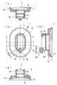
- FIG. 1A is a front view of the grommet 1.
- 1 (b), 1 (c), and 1 (d) show grommets having cut planes along the EE plane, the FF plane, and the GG plane shown in FIG. 1 (a), respectively.
- FIG. 1A is a front view of the grommet 1.
- 1 (b), 1 (c), and 1 (d) show grommets having cut planes along the EE plane, the FF plane, and the GG plane shown in FIG. 1 (a), respectively.
- the grommet 1 is a tool that is attached to a portion of the support 6 such as an automobile body where the through hole 6A is formed, and protects the wire harness 9 including the electric wire 7 and the corrugated tube 8.
- the through hole 6 ⁇ / b> A of the support 6 is a part of the passage of the wire harness 9.
- the grommet 1 covers and protects the periphery of the wire harness 9 passed through the through hole 6A of the support 6 and closes the gap between the wire harness 9 in the through hole 6A of the support 6 and has a waterproof function and a dustproof function. Fulfills the function.
- the grommet 1 is formed of a cylindrical elastic body surrounding the hollow portion 2 through which the wire harness 9 is passed, and includes a large diameter cylindrical portion 10 that is a relatively large outer diameter portion and a relatively small outer diameter portion. It has a certain small diameter cylinder part 20, and a first water stop part 50, a second water stop part 21 and a third water stop part 22 provided in the small diameter cylinder part 20. As shown in FIG. 6, the grommet 1 is attached to the edge of the through hole 6 ⁇ / b> A in the support body 6 in a state where it is combined with the inner 40 that is fitted inside the grommet 1.
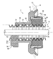
- FIG. 6 is a side sectional view of the grommet 1 combined with the inner 40 and the corrugated tube 8 of the wire harness 9.
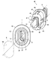
- FIG. 7 is a perspective view of each of the grommet 1 and the inner 40.
- FIG. 8 is an exploded perspective view of the inner 40.
- the wire harness 9 includes an electric wire 7 and a corrugated tube 8 that covers the periphery of the electric wire 7.
- the corrugated tube 8 is a cylindrical member that covers the periphery of the electric wire 7 and is an example of a protective tube through which the electric wire 7 is passed.
- the corrugated tube 8 has a bellows structure in which annular concave portions 81 and annular convex portions 82 are alternately formed on the surface along the longitudinal direction.
- the corrugated tube 8 is an integrally formed member made of a resin such as polyamide (PA), polypropylene (PP), polybutylene terephthalate (PBT), ABS resin, or polyethylene (PE).
- the corrugated tube 8 in the present embodiment is formed with a cut 8A along the longitudinal direction thereof.
- the cut 8 ⁇ / b> A is formed over the entire longitudinal direction of the corrugated tube 8.
- the corrugated tube 8 is disposed so that the cut 8A is positioned below.
- the cut 8A of the corrugated tube 8 is closed.
- the corrugated tube 8 is elastically deformed by being spread to both sides of the cut 8A, and the electric wire 7 is inserted into the corrugated tube 8 through a gap generated in the cut 8A. That is, the cut 8 ⁇ / b> A of the corrugated tube 8 functions as an entrance of the electric wire 7.
- the inner 40 is a member that is fitted inside the grommet 1 and is attached to the edge of the through hole 6 ⁇ / b> A of the support 6 together with the grommet 1.
- the inner 40 is a molded member made of a resin such as polyamide (PA), polypropylene (PP), polybutylene terephthalate (PBT), ABS resin, or polyethylene (PE).
- the inner 40 includes a main body portion 42 formed in a cylindrical shape surrounding the hollow portion 3 through which the corrugated tube 8 is passed, and a flange formed in a part of the main body portion 42. Part 43 and lock part 44.
- the flange portion 43 is a portion formed on the outer surface of one end of the cylindrical main body portion 42 so as to protrude further outward.
- the flange portion 43 is fitted into the inner groove 12 that is a groove formed along the circumferential direction inside the grommet 1.
- the lock portion 44 is formed in a cantilever shape on the outer portion of the main body portion 42 and is a portion that can be displaced in the direction from the outer side to the inner side of the main body portion 42.
- the lock portion 44 is displaced inward when the main body portion 42 is inserted into the through hole 6A of the support body 6, and then returns to the original state. Accordingly, the lock portion 44 of the inner 40 sandwiches the edge portion of the through hole 6 ⁇ / b> A in the support body 6 together with the lock portion 13 that is a part of the grommet 1, and fixes the grommet 1 and the inner 40 to the support body 6. That is, the lock part 13 of the grommet 1 and the lock part 44 of the inner 40 constitute a lock mechanism that fixes the grommet 1 and the inner 40 to the edge of the through hole 6 ⁇ / b> A in the support 6.
- a rib 45 that is a protrusion formed along the circumferential direction is formed on the inner surface of the main body 42 of the inner 40. As shown in FIG. 6, the rib 45 is a portion that fits into a recessed portion 81 on the outer surface of the corrugated tube 8 provided in the wire harness 9. When the rib 45 fits into the recessed portion 81 of the corrugated tube 8, the positional shift of the corrugated tube 8 with respect to the inner 40 is prevented.
- the inner 40 in the present embodiment is composed of two divided members 41 combined so as to sandwich the corrugated tube 8.
- the two divided members 41 are formed into a cylindrical shape by being combined from both sides of the corrugated tube 8.
- the ribs 45 provided on each of the divided members 41 fit into the recessed portions 81 of the corrugated tube 8.
- the two split members 41 are members having the same shape, and are provided with a lock mechanism that maintains the combined state with the split member 41 on the other side.
- the lock mechanism of the inner 40 illustrated in FIG. 5 includes an arm portion 46 provided with a protrusion 461 and an annular frame portion 47. By combining the two divided members 41, the arm portion 46 of one divided member 41 fits inside the frame portion 47 of the other divided member 41, and the protrusion 461 of the arm portion 46 is fixed to the frame portion 47. It will be caught on the edge 471. Thereby, the two division
- the grommet 1 is a member made of a material having elasticity.
- the grommet 1 is a member made of an elastomer (elastic polymer) that is a rubber or a rubber-based material as a whole.
- the elastomer includes vulcanized rubbers such as natural rubber and synthetic rubber, and thermosetting resin-based elastomers such as urethane rubber, silicone rubber and fluorine rubber.
- the large-diameter cylindrical portion 10 of the grommet 1 is a portion that covers the through hole 6 ⁇ / b> A of the support 6 while being in contact with the edge of the through hole 6 ⁇ / b> A of the support 6.
- the small diameter cylindrical portion 20 of the grommet 1 is a portion that is continuous with the large diameter cylindrical portion 10 and is formed with an outer diameter smaller than that of the large diameter cylindrical portion 10.
- a portion connected to the small diameter cylindrical portion 20 in the large diameter cylindrical portion 10 is referred to as a root portion of the large diameter cylindrical portion 10 and an end portion on the opposite side to the small diameter cylindrical portion 20 in the large diameter cylindrical portion 10 is large. This is referred to as the distal end portion of the diameter cylinder portion 10.
- the portion connected to the large-diameter cylindrical portion 10 in the small-diameter cylindrical portion 20 is referred to as a root portion of the small-diameter cylindrical portion 20, and the end of the small-diameter cylindrical portion 20 opposite to the large-diameter cylindrical portion 10 is the small-diameter cylindrical portion 20. This is referred to as the front end portion.
- annular frame portion 11 that is in close contact with an edge portion of the through hole 6 ⁇ / b> A in the support 6 is formed at the distal end portion of the large-diameter cylindrical portion 10.
- an inner groove 12 into which the flange portion 43 of the inner 40 is fitted is formed inside the large-diameter cylindrical portion 10.
- a lock portion 13 is formed on the inner side of the large-diameter cylindrical portion 10 together with the lock portion 44 of the inner 40 to sandwich the edge portion of the through hole 6 ⁇ / b> A in the support body 6. .
- the grommet 1 and the inner 40 are attached to the through hole 6 ⁇ / b> A portion of the support body 6, whereby the frame portion 11 of the large-diameter cylindrical portion 10 is deformed and the through hole 6 ⁇ / b> A in the support body 6 is deformed. And is in close contact with the edge of the through hole 6A. Thereby, the clearance gap between the edge part of 6 A of through-holes in the support body 6 and the wire harness 9 is block
- the grommet 1 includes a first water stop 50 provided at the tip of the small diameter cylindrical portion 20 and an annular formed on the inner surface of the small diameter portion.
- the 2nd water stop part 21 and the 3rd water stop part 22 which are these protrusion parts are provided.
- the whole grommet 1 including the 1st water stop part 50, the 2nd water stop part 21, and the 3rd water stop part 22 is an integral member which consists of an elastic body.
- the first water stop portion 50 is provided at the distal end portion of the small diameter cylindrical portion 20 and includes a base portion 51, a plate-like projection portion 52, a retaining portion 53, and a handle portion 54.
- the base 51 is a portion facing the outer surface of the cut portion 8 ⁇ / b> A in the corrugated tube 8 that passes through the small-diameter cylindrical portion 20 at the distal end of the small-diameter cylindrical portion 20. Since the corrugated tube 8 is arranged so that the cut 8A is located below, the grommet 1 is arranged so that the first water stop 50 is located below.
- the plate-like projecting portion 52 is a plate-like portion that is provided on the surface of the base portion 51 that faces the corrugated tube 8 and projects toward the inside of the corrugated tube 8 along the cut 8 ⁇ / b> A of the corrugated tube 8.
- the plate-like protrusion 52 is sandwiched between the cuts 8 ⁇ / b> A of the corrugated tube 8 that is passed through the small-diameter cylindrical portion 20.
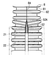
- 3 and 4 are cross-sectional views of the portion of the cut 8A of the corrugated tube 8 and the portion of the first water stop 50 in a state where the plate-like protrusion 52 is sandwiched between the cuts 8A.
- first edge 52A the edge of the plate-like protruding portion 52 opposite to the large-diameter cylindrical portion 10 side is referred to as a first edge 52A
- second edge 52B the edge of the plate-like protruding portion 52 toward the inside of the corrugated tube 8 is referred to as the first edge 52A.
- second edge 52B the edge of the plate-like protruding portion 52 toward the inside of the corrugated tube 8
- the portion on the first edge 52A side of the plate-like protrusion 52 is formed in a plate shape whose thickness gradually decreases toward the first edge 52A. That is, the portion on the first edge 52A side of the plate-like projection 52 is formed in a plate shape having two planes forming an acute angle, and the portion of the first edge 52A of the plate-like projection 52 is sharp. It is formed in a shape.
- the retaining portion 53 is a portion that is provided on the second edge 52B of the plate-like protrusion 52 and is formed with a thickness larger than the thickness of the plate-like protrusion 52.
- Two surfaces on the inner side of the corrugated tube 8 in the retaining portion 53 form acute corners along the cut line 8 ⁇ / b> A of the corrugated tube 8. Thereby, it becomes possible to smoothly insert the retaining portion 53 between the cuts 8 ⁇ / b> A of the corrugated tube 8.
- the base 51 and the retaining portion 53 are formed at intervals where the base 51 is in contact with the outer surface of the corrugated tube 8 and the retaining portion 53 is in contact with the inner surface of the corrugated tube 8. That is, the plate-like protrusion 52 is formed with a height that substantially matches the difference between the maximum outer diameter and the minimum inner diameter of the cut 8A portion of the corrugated tube 8. Therefore, the base 51 and the retaining portion 53 sandwich the corrugated tube 8 from the outside and the outside, and prevent the portion of the cut 8A of the corrugated tube 8 from being deformed inward or outward.
- the handle portion 54 is a portion formed by projecting from the base portion 51 which is the base portion of the plate-like projection portion 52 at the distal end portion of the small diameter cylindrical portion 20 toward the outside of the corrugated tube 8.
- the handle portion 54 is a portion that can be pinched and pulled, and as shown in FIG. 5, when the handle portion 54 is pulled, the small-diameter cylindrical portion 20 is stretched and deformed, and the plate-like protruding portion 52 and the removal portion are removed. A sufficient gap is formed between the stopper 53 and the corrugated tube 8 so that the plate-like protrusion 52 stands upright.
- the second water stop portion 21 is a protruding portion formed in an annular shape along the circumferential direction on the inner surface of the distal end portion of the small diameter cylindrical portion 20.
- the 2nd water stop part 21 is formed in the shape which fits in the recessed part 81 of the outer surface of the corrugated tube 8 with which the wire harness 9 is equipped, and seals the recessed part 81.
- the plate-like protrusion 52 of the first water stop 50 is formed continuously with the second water stop 21.
- the third water stop portion 22 is a protrusion formed in an annular shape along the circumferential direction on the inner surface of the small diameter tube portion 20 at a position closer to the large diameter tube portion 10 than the position of the second water stop portion 21. .
- the 3rd water stop part 22 is formed in the shape lower than the 2nd water stop part 21, and the shape which fits the recessed part 81 of the outer surface of the corrugated tube 8 with which the wire harness 9 is equipped, and seals the recessed part 81 Has been.
- the third water stop portion 22 is formed with a height that reaches the surface layer portion of the recessed portion 81 of the corrugated tube 8.
- the second water stop portion 21 and the third water stop portion 22 are formed side by side in the axial direction of the small diameter cylindrical portion 20, and both the second water stop portion 21 and the third water stop portion 22 are formed.
- the corrugated tube 8 is fitted into the recessed portion 81. Therefore, the second water stop portion 21 and the third water stop portion 22 are formed so that the center interval in the axial direction of the small diameter cylindrical portion 20 matches an integral multiple of the pitch of the plurality of recess portions 81 in the corrugated tube 8.
- the center interval between the second water stop portion 21 and the third water stop portion 22 in the axial direction of the small diameter cylindrical portion 20 is 2 of the pitch of the plurality of recess portions 81 in the corrugated tube 8. Match twice.
- the plate-like protrusion 52 is sandwiched between the cuts 8 ⁇ / b> A of the corrugated tube 8, and blocks liquid such as water that travels along the cuts 8 ⁇ / b> A of the corrugated tube 8 toward the inside of the grommet 1. Therefore, by adopting the grommet 1, it is possible to prevent the liquid adhering to the corrugated tube 8 from entering the inside of the grommet 1 along the cut 8 ⁇ / b> A of the corrugated tube 8.
- the plate-like protrusion 52 is formed in a plate shape that gradually decreases in thickness toward the first edge 52A. Therefore, as shown in FIG. 4, the portion of the cut 8 ⁇ / b> A of the corrugated tube 8 extends along two planes forming an acute angle in the plate-like protrusion 52. Accordingly, it is possible to prevent a large gap from being generated between the portion of the cut 8 ⁇ / b> A in the corrugated tube 8 and the plate-like protrusion 52 and foreign matter from entering the corrugated tube 8 from the gap.
- the plate-like projection 52 can be prevented from coming off from between the cuts 8A of the corrugated tube 8.
- the corrugated tube 8 of the wire harness 9 is passed through the small-diameter cylindrical portion 20 in the grommet 1, the second water stop portion 21 and the third water stop portion 22 are fitted in the recessed portion 81 on the outer surface of the corrugated tube 8.
- the gap between the small diameter cylindrical portion 20 and the corrugated tube 8 is closed. That is, if the grommet 1 is employed, the gap between the wire harness 9 provided with the corrugated tube 8 and the grommet 1 is closed by a simple operation of passing the corrugated tube 8 through the hollow portion 2 of the cylindrical grommet 1 and is waterproof. And dustproof can be realized.
- the second water stop portion 21 is formed on the inner surface of the distal end portion of the small diameter cylindrical portion 20, it is easy to confirm that the second water stop portion 21 has been correctly fitted into the recessed portion 81 of the corrugated tube 8. It is.
- the two-stage fitting structure by the second water stop portion 21 and the third water stop portion 22 more reliably fulfills the waterproof and dustproof functions between the corrugated tube 8 and the grommet 1.
- the second water stop portion 21 and the third water stop portion 22 are formed at intervals corresponding to the pitch of the recessed portions 81 of the corrugated tube 8. Therefore, as long as it is confirmed that the second water stop 21 is correctly fitted in the recess 81 of the corrugated tube 8, the third water stop 22 is also securely fitted in the recess 81 of the corrugated tube 8.
- the 3rd water stop part 22 is formed lower than the 2nd water stop part 21, the resistance at the time of the corrugated tube 8 being passed through the small diameter cylinder part 20 is restrained comparatively small.
- Grommet 1A has a configuration in which only the shape of large-diameter cylindrical portion 10 is different from that of grommet 1 shown in FIGS.
- FIGS. Hereinafter, only the points of the grommet 1A different from the grommet 1 will be described.
- FIG. 9 is a cross-sectional view of the grommet 1A and corresponds to the cross-sectional view of the grommet 1 shown in FIG.
- the same components as those shown in FIGS. 1 to 6 are given the same reference numerals.
- the wire harness 9 and the support body 6 are shown by the virtual line (two-dot chain line).
- the grommet 1A is a grommet that is attached to the edge of the through hole 6A in the support 6 without the inner 40.
- An outer groove 14 that is an annular groove formed along the circumferential direction is formed on the outer surface of the large-diameter cylindrical portion 10 of the grommet 1A.
- the grommet 1A is only passed in one direction with respect to the through-hole 6A of the support 6, and the edge of the through-hole 6A in the support 6 is formed in the outer groove 14 formed on the outer periphery of the large-diameter cylindrical portion 10 in the grommet 1A. Is fitted and fixed to the support 6.
- Such a grommet 1A is referred to as a one-motion type grommet.
- the wire harness 9 provided with the corrugated tube 8 is passed through the hollow portion 2 of the cylindrical grommet 1A.
- the large diameter cylindrical portion 10 is formed with a width wider than the width of the through hole 6 ⁇ / b> A of the support 6.
- the outer shape contracts, and the edge of the through-hole 6 ⁇ / b> A in the support 6 fits into the outer groove 14 of the large-diameter cylindrical portion 10.
- a tape winding portion 15 formed to extend along the wire harness 9 is formed in the large diameter cylindrical portion 10 of the grommet 1A.
- the adhesive tape is wound around the tape winding part 15 and the corrugated tube 8 of the wire harness 9 so as to bundle them, so that the grommet 1 ⁇ / b> A is fixed to the corrugated tube 8.
- the grommet 1A includes a small-diameter cylindrical portion 20 that is continuous with the large-diameter cylindrical portion 10 like the grommet 1, and the small-diameter cylindrical portion 20 includes the first water stopping portion 50, the second water stopping portion 21, and the third water stopping portion.
- a water part 22 is provided.
- the grommet 1A shown in FIG. 9 When the grommet 1A shown in FIG. 9 is adopted, the same effect as that obtained when the grommet 1 is adopted can be obtained. That is, the grommet to which the present invention is applied is not necessarily limited to the grommet combined with the inner 40.
- the grommets 1, 1 ⁇ / b> A according to each embodiment shown above have the remaining configuration excluding one or both of the second water stop portion 21 and the third water stop portion 22.
- the first water stop portion 50 has a remaining configuration excluding one or both of the retaining portion 53 and the handle portion.
- tip part of the small diameter cylinder part 20 can also serve as the base 51.
- the protective tube provided in the wire harness 9 passed through the grommets 1, 1 ⁇ / b> A is a protective tube other than the corrugated tube 8.
- the protective tube is a protective tube that is formed in a round cylindrical shape or a rectangular cylindrical shape with no irregularities on the outer surface, and a cut is formed in the longitudinal direction thereof.
- the base portion 51 and the retaining portion 53 of the first water stop portion 50 are formed at intervals that substantially coincide with the thickness of the cut portion of the protective tube. That is, the plate-like protrusion 52 is formed with a height that substantially matches the thickness of the cut portion of the protective tube. Moreover, the 2nd water stop part 21 and the 3rd water stop part 22 are formed in the same height, or one or both of them is removed.
Landscapes
- Engineering & Computer Science (AREA)
- Architecture (AREA)
- Civil Engineering (AREA)
- Structural Engineering (AREA)
- Insulating Bodies (AREA)
- Installation Of Indoor Wiring (AREA)
Abstract
本発明は、グロメット(1)に通されるワイヤハーネス(9)が、切れ目(8A)の形成された保護チューブ(8)を備える場合に、保護チューブ(8)に付着した液体が、保護チューブの切れ目(8A)を伝ってグロメット(1)の内側へ浸入することを防止することを目的とする。グロメット1の大径筒部(10)は、支持体の貫通孔(6A)の縁部に接しつつ支持体の貫通孔(6A)を覆う。グロメット(1)の小径筒部(20)は、大径筒部(10)と連なり大径筒部(10)よりも小さな外径で形成された部分である。小径筒部(20)の先端部には、保護チューブの切れ目(8A)に沿って保護チューブ(8)の内側へ向かって突起し、保護チューブの切れ目(8A)に挟み込まれる板状突起部(52)が形成されている。板状突起部(52)の少なくとも一部は、大径筒部(10)側に対して反対側の縁(52A)へ向かうほど徐々に厚みが薄くなる板状に形成されている。
Description
本発明は、自動車のボディなどの支持体の貫通孔の部分においてその貫通孔に通されるワイヤハーネスを保護するグロメットに関する。
グロメットは、ワイヤハーネスが通される筒状の弾性体からなり、自動車のボディなどの支持体における貫通孔が形成された部分に取り付けられる。グロメットは、支持体の貫通孔に通されるワイヤハーネスを保護するとともに、支持体の貫通孔におけるワイヤハーネスとの間の隙間を塞ぎ、防水機能及び防塵機能を果たす。
一般に、グロメットは、特許文献1の図5に示されるように、支持体の貫通孔の縁部に接しつつその貫通孔を覆う大径の筒部と、その大径の筒部と連なり、大径の筒部よりも小さな外径で形成された小径の筒部とを有する。大径の筒部は、支持体の貫通孔におけるワイヤハーネスとの間の隙間を塞ぐ機能を果たし、小径の筒部は、グロメットとワイヤハーネスとの間の隙間を塞ぐ機能を果たす。
また、特許文献1には、グロメットとは別体の小径の筒部が、グロメットの内側に嵌め入れられた構造についても示されている。この場合、粘着テープが、グロメットの内側の小径の筒部及びワイヤハーネスに対して巻き付けられることにより、グロメットとワイヤハーネスとの間の隙間が塞がれる。
ところで、グロメットに通されるワイヤハーネスが、その外装を形成する保護具として、長手方向に沿う切れ目が形成された保護チューブを備える場合がある。この場合、保護チューブは、切れ目の両側へ広げられ、電線は、切れ目の部分に生じる隙間から保護チューブ内に挿入される。即ち、保護チューブの切れ目は、電線の入口として機能する。
グロメットに通されるワイヤハーネスが、切れ目の形成された保護チューブを備える場合、保護チューブに付着した液体が、保護チューブの切れ目における隙間を伝ってグロメットの内側へ浸入しやすい。即ち、従来のグロメットは、保護チューブに付着した液体が、保護チューブの切れ目を伝って内側へ浸入することを防ぐ構造を備えていないという問題点を有している。
本発明は、グロメットに通されるワイヤハーネスが、切れ目の形成された保護チューブを備える場合に、保護チューブに付着した液体が、保護チューブの切れ目を伝ってグロメットの内側へ浸入することを防止できることを目的とする。
本発明に係るグロメットは、長手方向に沿う切れ目が形成された保護チューブを備えるワイヤハーネスが通される筒状の弾性体からなり、以下の各構成要素を備える。
(1)第1の構成要素は、支持体の貫通孔の縁部に接しつつ前記支持体の貫通孔を覆う第一筒部である。
(2)第2の構成要素は、前記第一筒部と連なり前記第一筒部よりも小さな外径で形成された第二筒部である。
(3)第3の構成要素は、前記第二筒部の先端部に設けられ、前記保護チューブの前記切れ目に沿って前記保護チューブの内側へ向かって突起し、前記保護チューブの前記切れ目に挟み込まれる板状突起部である。
(1)第1の構成要素は、支持体の貫通孔の縁部に接しつつ前記支持体の貫通孔を覆う第一筒部である。
(2)第2の構成要素は、前記第一筒部と連なり前記第一筒部よりも小さな外径で形成された第二筒部である。
(3)第3の構成要素は、前記第二筒部の先端部に設けられ、前記保護チューブの前記切れ目に沿って前記保護チューブの内側へ向かって突起し、前記保護チューブの前記切れ目に挟み込まれる板状突起部である。
また、本発明に係るグロメットにおいて、前記板状突起部の少なくとも一部が、前記第一筒部側に対して反対側の第一の縁へ向かうほど徐々に厚みが薄くなる板状に形成されていることが考えられる。
また、本発明に係るグロメットが、さらに以下の構成要素を備えれば好適である。
(4)第4の構成要素は、前記板状突起部における前記保護チューブの内側に向かう側の第二の縁に設けられ、前記板状突起部の厚みよりも大きな厚みで形成された抜け止め部である。
(4)第4の構成要素は、前記板状突起部における前記保護チューブの内側に向かう側の第二の縁に設けられ、前記板状突起部の厚みよりも大きな厚みで形成された抜け止め部である。
また、本発明に係るグロメットが、さらに以下の構成要素を備えれば好適である。
(5)第5の構成要素は、前記第二筒部の先端部における前記板状突起部の根元部分から前記保護チューブの外側へ向かって突起して形成された取手部である。
(5)第5の構成要素は、前記第二筒部の先端部における前記板状突起部の根元部分から前記保護チューブの外側へ向かって突起して形成された取手部である。
本発明に係るグロメットにおいて、板状突起部は、保護チューブの切れ目に挟み込まれ、保護チューブの切れ目を伝ってグロメットの内側へ向かう液体を遮る。従って、本発明に係るグロメットが採用されることにより、保護チューブに付着した液体が、保護チューブの切れ目を伝ってグロメットの内側へ浸入することを防止できる。
また、板状突起部が、第一筒部側に対して反対側の縁へ向かうほど徐々に厚みが薄くなる板状、即ち、鋭角をなす二平面を有する板状に形成されていれば、保護チューブの切れ目の部分は、その鋭角をなす二平面に沿って広がる。従って、保護チューブにおける切れ目の部分と板状突起部との間に大きな隙間が生じてその隙間から保護チューブ内へ異物が入り込むことを防止できる。
また、本発明に係るグロメットにおいて、板状突起部における保護チューブの内側の縁に抜け止め部が設けられていることが望ましい。これにより、板状突起部が、保護チューブの切れ目の間から外れることを防止できる。
ところで、弾性体からなる板状突起部は折れ曲がりやすく、折れ曲がった板状突起部を保護チューブの切れ目にうまく挿入することは難しい。そこで、第二筒部の先端部における板状突起部の位置に、つまんで引っ張ることができる取手部が設けられていれば好適である。取手部が引っ張られることにより、第二筒部が引き伸ばされ、板状突起部と保護チューブとの間に、板状突起部が真っ直ぐに起立するのに十分な隙間が形成される。そして、起立した板状突起部の縁が保護チューブの切れ目に沿う状態で、取手部を引っ張る力が緩められれば、板状突起部がスムーズに保護チューブの切れ目に挿入される。
以下、添付の図面を参照しながら、本発明の実施形態について説明する。以下の実施形態は、本発明を具体化した一例であって、本発明の技術的範囲を限定するものではない。
<第1実施形態>
まず、図1から図6を参照しつつ、本発明の第1実施形態に係るグロメット1の構成について説明する。なお、図1(a)は、グロメット1の正面図である。また、図1(b)、図1(c)及び図1(d)は、それぞれ図1(a)に示されるE-E平面、F-F平面及びG-G平面を切断面とするグロメット1の断面図である。
まず、図1から図6を参照しつつ、本発明の第1実施形態に係るグロメット1の構成について説明する。なお、図1(a)は、グロメット1の正面図である。また、図1(b)、図1(c)及び図1(d)は、それぞれ図1(a)に示されるE-E平面、F-F平面及びG-G平面を切断面とするグロメット1の断面図である。
グロメット1は、自動車のボディなどの支持体6における貫通孔6Aが形成された部分に取り付けられ、電線7及びコルゲートチューブ8を備えたワイヤハーネス9を保護する用具である。支持体6の貫通孔6Aは、ワイヤハーネス9の通路の一部である。グロメット1は、支持体6の貫通孔6Aに通されるワイヤハーネス9の周囲を覆って保護するとともに、支持体6の貫通孔6Aにおけるワイヤハーネス9との間の隙間を塞ぎ、防水機能及び防塵機能を果たす。
グロメット1は、ワイヤハーネス9が通される中空部2を囲む筒状の弾性体からなり、相対的に外径の大きな部分である大径筒部10と、相対的に外径の小さな部分である小径筒部20と、小径筒部20に設けられた第一止水部50、第二止水部21及び第三止水部22を有している。図6に示されるように、グロメット1は、その内側に嵌め入れられるインナー40と組み合わされた状態で、支持体6における貫通孔6Aの縁部に取り付けられる。
ここで、図6から図8を参照しつつ、ワイヤハーネス9と、グロメット1と組み合わされるインナー40とについて説明する。図6は、インナー40及びワイヤハーネス9のコルゲートチューブ8と組み合わされたグロメット1の側面側の断面図である。また、図7は、グロメット1及びインナー40各々の斜視図である。また、図8は、インナー40の分解斜視図である。図6から図8に示されるように、ワイヤハーネス9は、電線7とその電線7の周囲を覆うコルゲートチューブ8とを備えている。
<コルゲートチューブ>
コルゲートチューブ8は、電線7の周囲を覆う筒状の部材であり、電線7が通される保護チューブの一例である。コルゲートチューブ8は、長手方向に沿って表面に環状の凹み部81と環状の凸部82とが交互に形成された蛇腹構造を有する。コルゲートチューブ8は、例えば、ポリアミド(PA)、ポリプロピレン(PP)、ポリブチレンテレフタレート(PBT)、ABS樹脂又はポリエチレン(PE)などの樹脂からなる一体成形部材である。
コルゲートチューブ8は、電線7の周囲を覆う筒状の部材であり、電線7が通される保護チューブの一例である。コルゲートチューブ8は、長手方向に沿って表面に環状の凹み部81と環状の凸部82とが交互に形成された蛇腹構造を有する。コルゲートチューブ8は、例えば、ポリアミド(PA)、ポリプロピレン(PP)、ポリブチレンテレフタレート(PBT)、ABS樹脂又はポリエチレン(PE)などの樹脂からなる一体成形部材である。
また、図4、図5、図7及び図8に示されるように、本実施形態におけるコルゲートチューブ8には、その長手方向に沿う切れ目8Aが形成されている。切れ目8Aは、コルゲートチューブ8における長手方向全体に渡って形成されている。コルゲートチューブ8は、その切れ目8Aが下方に位置するように配置される。
コルゲートチューブ8に外部からの力が加わらない状態において、コルゲートチューブ8の切れ目8Aは閉じている。コルゲートチューブ8は、切れ目8Aの両側へ広げられることによって弾性変形し、電線7は、切れ目8Aの部分に生じる隙間からコルゲートチューブ8内に挿入される。即ち、コルゲートチューブ8の切れ目8Aは、電線7の入口として機能する。
<インナー>
インナー40は、グロメット1の内側に嵌め入れられる部材であり、グロメット1とともに支持体6の貫通孔6Aの縁部に取り付けられる。インナー40は、例えば、ポリアミド(PA)、ポリプロピレン(PP)、ポリブチレンテレフタレート(PBT)、ABS樹脂又はポリエチレン(PE)などの樹脂からなる成形部材である。
インナー40は、グロメット1の内側に嵌め入れられる部材であり、グロメット1とともに支持体6の貫通孔6Aの縁部に取り付けられる。インナー40は、例えば、ポリアミド(PA)、ポリプロピレン(PP)、ポリブチレンテレフタレート(PBT)、ABS樹脂又はポリエチレン(PE)などの樹脂からなる成形部材である。
図6及び図7に示されるように、インナー40は、コルゲートチューブ8が通される中空部3を囲む筒状に形成された本体部42と、その本体部42の一部に形成されたフランジ部43及びロック部44とを備える。
フランジ部43は、筒状の本体部42における一端の外側面に、さらに外側へ張り出して形成された部分である。フランジ部43は、グロメット1の内側に周方向に沿って形成された溝である内側溝12に嵌め入れられる。フランジ部43がグロメット1の内側溝12に嵌め入れられることにより、グロメット1及びインナー40は一体に組み合わされる。
ロック部44は、本体部42の外側の部分に片持ち梁状に形成され、本体部42の外側から内側へ向かう方向へ変位可能な部分である。ロック部44は、本体部42が支持体6の貫通孔6Aに挿入される際に内側へ変位し、その後、元の状態へ戻る。これにより、インナー40のロック部44は、グロメット1の一部であるロック部13とともに支持体6における貫通孔6Aの縁部を挟み込み、グロメット1及びインナー40を支持体6に固定する。即ち、グロメット1のロック部13及びインナー40のロック部44は、グロメット1及びインナー40を支持体6における貫通孔6Aの縁部に固定するロック機構を構成する。
また、インナー40の本体部42の内側の面には、周方向に沿って形成された突起部であるリブ45が形成されている。このリブ45は、図6に示されるように、ワイヤハーネス9が備えるコルゲートチューブ8の外面の凹み部81に嵌る部分である。リブ45がコルゲートチューブ8の凹み部81に嵌ることにより、インナー40に対するコルゲートチューブ8の位置ずれが防止される。
図8に示されるように、本実施形態におけるインナー40は、コルゲートチューブ8を挟み込むように組み合わされる2つの分割部材41から構成されている。2つの分割部材41は、コルゲートチューブ8の両側から組み合わされることによって筒状となる。また、2つの分割部材41がコルゲートチューブ8の両側から組み合わされる際に、分割部材41の各々に設けられたリブ45が、コルゲートチューブ8の凹み部81に嵌り込む。
2つの分割部材41は、同じ形状の部材であり、相手側の分割部材41と組み合わされた状態を維持するロック機構を備えている。図5に例示されるインナー40のロック機構は、突起461が設けられたアーム部46と、環状の枠部47とにより構成されている。2つの分割部材41が組み合わされることにより、一方の分割部材41におけるアーム部46が、他方の分割部材41における枠部47の内側に嵌り込むとともに、アーム部46の突起部461が、枠部47の縁471に引っ掛かる。これにより、2つの分割部材41は筒状に組み合わされた状態で維持される。
<グロメットの詳細な構造>
以下、グロメット1の詳細な構造について説明する。グロメット1は、弾性を有する材料からなる部材であり、例えば、それ全体がゴム又はゴム系材料であるエラストマー(elastic polymer)からなる部材である。なお、エラストマーには、天然ゴム及び合成ゴムなどの加硫ゴム、並びにウレタンゴム、シリコーンゴム及びフッ素ゴムなどの熱硬化性樹脂系エラストマーが含まれる。
以下、グロメット1の詳細な構造について説明する。グロメット1は、弾性を有する材料からなる部材であり、例えば、それ全体がゴム又はゴム系材料であるエラストマー(elastic polymer)からなる部材である。なお、エラストマーには、天然ゴム及び合成ゴムなどの加硫ゴム、並びにウレタンゴム、シリコーンゴム及びフッ素ゴムなどの熱硬化性樹脂系エラストマーが含まれる。
図6に示されるように、グロメット1の大径筒部10は、支持体6の貫通孔6Aの縁部に接しつつ支持体6の貫通孔6Aを覆う部分である。また、グロメット1の小径筒部20は、大径筒部10と連なり、大径筒部10よりも小さな外径で形成された部分である。
以下の説明において、大径筒部10における小径筒部20に繋がる部分を大径筒部10の根元部と称し、大径筒部10における小径筒部20に対して反対側の端部を大径筒部10の先端部と称する。同様に、小径筒部20における大径筒部10に繋がる部分を小径筒部20の根元部と称し、小径筒部20における大径筒部10に対して反対側の端部を小径筒部20の先端部と称する。
図1、図2及び図6に示されるように、大径筒部10の先端部には、支持体6における貫通孔6Aの縁部に密接する環状の枠部11が形成されている。また、図1及び図2に示されるように、大径筒部10の内側には、インナー40のフランジ部43が嵌め入れられる内側溝12が形成されている。さらに、図1及び図6に示されるように、大径筒部10の内側には、インナー40のロック部44とともに支持体6における貫通孔6Aの縁部を挟み込むロック部13が形成されている。
図6に示されるように、グロメット1及びインナー40が支持体6の貫通孔6Aの部分に取り付けられることにより、大径筒部10の枠部11は、変形しつつ支持体6における貫通孔6Aの縁部に押し付けられ、貫通孔6Aの縁部に密接する。これにより、支持体6における貫通孔6Aの縁部とワイヤハーネス9との間の隙間が塞がれる。
また、図1、図2及び図6に示されるように、グロメット1は、小径筒部20の先端部に設けられた第一止水部50と、小径部の内側の面に形成された環状の突起部である第二止水部21及び第三止水部22とを備えている。なお、第一止水部50、第二止水部21及び第三止水部22を含むグロメット1全体が、弾性体からなる一体の部材である。
<第一止水部>
第一止水部50は、小径筒部20の先端部に設けられ、基部51、板状突起部52、抜け止め部53及び取手部54を含む。基部51は、小径筒部20の先端部において、小径筒部20に通されるコルゲートチューブ8における切れ目8Aの部分の外側面に対向する部分である。コルゲートチューブ8は、その切れ目8Aが下方に位置するように配置されるため、グロメット1は、その第一止水部50が下方に位置するように配置される。
第一止水部50は、小径筒部20の先端部に設けられ、基部51、板状突起部52、抜け止め部53及び取手部54を含む。基部51は、小径筒部20の先端部において、小径筒部20に通されるコルゲートチューブ8における切れ目8Aの部分の外側面に対向する部分である。コルゲートチューブ8は、その切れ目8Aが下方に位置するように配置されるため、グロメット1は、その第一止水部50が下方に位置するように配置される。
板状突起部52は、基部51におけるコルゲートチューブ8に対向する面に設けられ、コルゲートチューブ8の切れ目8Aに沿ってコルゲートチューブ8の内側へ向かって突起した板状の部分である。この板状突起部52は、小径筒部20に通されるコルゲートチューブ8の切れ目8Aに挟み込まれる。なお、図3及び図4は、コルゲートチューブ8の切れ目8Aの部分、及び板状突起部52がその切れ目8Aに挟み込まれた状態における第一止水部50の部分の断面図である。
以下の説明において、板状突起部52における大径筒部10側に対して反対側の縁を第一の縁52Aと称し、板状突起部52におけるコルゲートチューブ8の内側に向かう側の縁を第二の縁52Bと称する。
図2及び図4に示されるように、板状突起部52における第一の縁52A側の部分は、第一の縁52Aへ向かうほど徐々に厚みが薄くなる板状に形成されている。即ち、板状突起部52における第一の縁52A側の部分は、鋭角をなす二平面を有する板状に形成されており、板状突起部52の第一の縁52Aの部分は、先鋭な形状で形成されている。
なお、板状突起部52全体が、第一の縁52Aへ向かうほど徐々に厚みが薄くなる板状に形成された構成が採用されることも考えられる。
また、抜け止め部53は、板状突起部52における第二の縁52Bに設けられ、板状突起部52の厚みよりも大きな厚みで形成された部分である。抜け止め部53におけるコルゲートチューブ8の内側へ向かう側の二面は、コルゲートチューブ8の切れ目8Aに沿う鋭角の角部を形成している。これにより、抜け止め部53をコルゲートチューブ8の切れ目8Aの間へスムーズに挿入することが可能となる。
また、基部51及び抜け止め部53は、基部51がコルゲートチューブ8の外側面に接し、かつ、抜け止め部53がコルゲートチューブ8の内側面に接する間隔で形成されている。即ち、板状突起部52は、コルゲートチューブ8における切れ目8Aの部分の最大外径と最小内径との差とほぼ一致する高さで形成されている。そのため、基部51及び抜け止め部53は、コルゲートチューブ8をその外側及び外側から挟み込み、コルゲートチューブ8の切れ目8Aの部分が内側又は外側へ変形することを防止する。
また、取手部54は、小径筒部20の先端部における板状突起部52の根元部分である基部51からコルゲートチューブ8の外側へ向かって突起して形成された部分である。取手部54は、つまんで引っ張ることができる部分であり、図5に示されるように、取手部54が引っ張られることにより、小径筒部20が引き伸ばされて変形し、板状突起部52及び抜け止め部53とコルゲートチューブ8との間に、板状突起部52が真っ直ぐに起立するのに十分な隙間が形成される。
<第二止水部>
第二止水部21は、小径筒部20の先端部の内面に周方向に沿って環状に形成された突起部である。第二止水部21は、ワイヤハーネス9が備えるコルゲートチューブ8の外面の凹み部81に嵌ってその凹み部81を密閉する形状で形成されている。図6に示される例では、第二止水部21は、コルゲートチューブ8の凹み部81の底にほぼ達する程度の高さで形成されている。
第二止水部21は、小径筒部20の先端部の内面に周方向に沿って環状に形成された突起部である。第二止水部21は、ワイヤハーネス9が備えるコルゲートチューブ8の外面の凹み部81に嵌ってその凹み部81を密閉する形状で形成されている。図6に示される例では、第二止水部21は、コルゲートチューブ8の凹み部81の底にほぼ達する程度の高さで形成されている。
なお、本実施形態においては、図2に示されるように、第一止水部50の板状突起部52は、第二止水部21と連なって形成されている。
<第三止水部>
一方、第三止水部22は、小径筒部20における第二止水部21の位置よりも大径筒部10に近い位置の内面に周方向に沿って環状に形成された突起部である。第三止水部22は、第二止水部21よりも低い高さで、かつ、ワイヤハーネス9が備えるコルゲートチューブ8の外面の凹み部81に嵌ってその凹み部81を密閉する形状で形成されている。図6に示される例では、第三止水部22は、コルゲートチューブ8の凹み部81の表層部分に達する程度の高さで形成されている。
一方、第三止水部22は、小径筒部20における第二止水部21の位置よりも大径筒部10に近い位置の内面に周方向に沿って環状に形成された突起部である。第三止水部22は、第二止水部21よりも低い高さで、かつ、ワイヤハーネス9が備えるコルゲートチューブ8の外面の凹み部81に嵌ってその凹み部81を密閉する形状で形成されている。図6に示される例では、第三止水部22は、コルゲートチューブ8の凹み部81の表層部分に達する程度の高さで形成されている。
第二止水部21及び第三止水部22は、小径筒部20の軸心方向において間隔を空けて並んで形成され、第二止水部21及び第三止水部22の両方が、コルゲートチューブ8の凹み部81に嵌る。そのため、第二止水部21及び第三止水部22は、小径筒部20の軸心方向における中心間隔が、コルゲートチューブ8における複数の凹み部81のピッチの整数倍に一致するように形成されている。なお、図6に示される例では、小径筒部20の軸心方向における第二止水部21及び第三止水部22の中心間隔は、コルゲートチューブ8における複数の凹み部81のピッチの2倍に一致する。
<効果>
グロメット1において、板状突起部52は、コルゲートチューブ8の切れ目8Aに挟み込まれ、コルゲートチューブ8の切れ目8Aを伝ってグロメット1の内側へ向かう水などの液体を遮る。従って、グロメット1が採用されることにより、コルゲートチューブ8に付着した液体が、コルゲートチューブ8の切れ目8Aを伝ってグロメット1の内側へ浸入することを防止できる。
グロメット1において、板状突起部52は、コルゲートチューブ8の切れ目8Aに挟み込まれ、コルゲートチューブ8の切れ目8Aを伝ってグロメット1の内側へ向かう水などの液体を遮る。従って、グロメット1が採用されることにより、コルゲートチューブ8に付着した液体が、コルゲートチューブ8の切れ目8Aを伝ってグロメット1の内側へ浸入することを防止できる。
また、板状突起部52が、第一の縁52Aへ向かうほど徐々に厚みが薄くなる板状に形成されている。そのため、図4に示されるように、コルゲートチューブ8の切れ目8Aの部分は、板状突起部52における鋭角をなす二平面に沿って広がる。従って、コルゲートチューブ8における切れ目8Aの部分と板状突起部52との間に大きな隙間が生じてその隙間からコルゲートチューブ8内へ異物が入り込むことを防止できる。
また、板状突起部52の第二の縁52Bに抜け止め部53が設けられているため、板状突起部52が、コルゲートチューブ8の切れ目8Aの間から外れることを防止できる。
また、図5に示されるように、取手部54が引っ張られることにより、小径筒部20が引き伸ばされ、板状突起部52が真っ直ぐに起立する。そして、起立した板状突起部52の第二の縁52B、即ち、抜け止め部53がコルゲートチューブ8の切れ目8Aに沿う状態で、取手部54を引っ張る力が緩められれば、抜け止め部53及び板状突起部52がスムーズにコルゲートチューブ8の切れ目8Aに挿入される。
また、ワイヤハーネス9のコルゲートチューブ8が、グロメット1における小径筒部20に通されると、第二止水部21及び第三止水部22が、コルゲートチューブ8の外面の凹み部81に嵌り、小径筒部20とコルゲートチューブ8との隙間が塞がれる。即ち、グロメット1が採用されれば、コルゲートチューブ8を筒状のグロメット1の中空部2に通すという簡易な作業により、コルゲートチューブ8を備えたワイヤハーネス9とグロメット1との隙間を塞いで防水及び防塵を実現できる。
また、第二止水部21は、小径筒部20の先端部の内面に形成されているため、第二止水部21がコルゲートチューブ8の凹み部81に正しく嵌り込んだことの確認が容易である。
また、第二止水部21及び第三止水部22による二段階の嵌め合い構造が、より確実にコルゲートチューブ8とグロメット1との間の防水及び防塵の機能を果たす。また、第二止水部21及び第三止水部22は、コルゲートチューブ8の凹み部81のピッチに対応した間隔で形成されている。そのため、第二止水部21がコルゲートチューブ8の凹み部81に正しく嵌り込んでいることさえ確認されれば、第三止水部22も確実にコルゲートチューブ8の凹み部81に正しく嵌る。また、第三止水部22は、第二止水部21よりも低く形成されているため、コルゲートチューブ8が小径筒部20に通される際の抵抗は比較的小さく抑えられる。
<第2実施形態>
次に、図9を参照しつつ、本発明の第2実施形態に係るグロメット1Aについて説明する。グロメット1Aは、図1から図6に示されたグロメット1と比較して、大径筒部10の形状のみが異なる構成を有している。以下、グロメット1Aにおけるグロメット1と異なる点についてのみ説明する。
次に、図9を参照しつつ、本発明の第2実施形態に係るグロメット1Aについて説明する。グロメット1Aは、図1から図6に示されたグロメット1と比較して、大径筒部10の形状のみが異なる構成を有している。以下、グロメット1Aにおけるグロメット1と異なる点についてのみ説明する。
図9は、グロメット1Aの断面図であり、図6に示されるグロメット1の断面図に相当する。なお、図9において、図1から図6に示される構成要素と同じ構成要素は、同じ参照符号が付されている。また、図9において、ワイヤハーネス9及び支持体6が仮想線(二点鎖線)によって示されている。
グロメット1Aは、インナー40なしで支持体6における貫通孔6Aの縁部に取り付けられるグロメットである。グロメット1Aの大径筒部10の外側の面には、周方向に沿って形成された環状の溝である外側溝14が形成されている。支持体6における貫通孔6Aの縁部が大径筒部10の外側溝14に嵌り込むと、外側溝14の両側壁を形成する第一枠部11A及び第二枠部11Bが、支持体6における貫通孔6Aの縁部の表裏両側の面に接し、大径筒部10は、支持体6の貫通孔6Aを覆う。
グロメット1Aは、支持体6の貫通孔6Aに対して一方向に通されるだけで、グロメット1Aにおける大径筒部10外周に形成された外側溝14に支持体6における貫通孔6Aの縁部が嵌り込み、支持体6に固定される。このようなグロメット1Aは、ワンモーションタイプのグロメットなどと称される。
また、コルゲートチューブ8を備えたワイヤハーネス9は、筒状のグロメット1Aの中空部2に通される。大径筒部10は、支持体6の貫通孔6Aの幅よりも広い幅で形成されている。大径筒部10は、支持体6の貫通孔6Aに挿入される際に外形が収縮し、支持体6における貫通孔6Aの縁部が大径筒部10の外側溝14に嵌り込む。
また、グロメット1Aの大径筒部10には、ワイヤハーネス9に沿って伸びて形成されたテープ巻き部15が形成されている。粘着テープが、テープ巻き部15及びワイヤハーネス9のコルゲートチューブ8に対してそれらを束ねるように巻き付けられることにより、グロメット1Aがコルゲートチューブ8に対して固定される。
また、グロメット1Aは、グロメット1と同様に、大径筒部10に連なる小径筒部20を備え、小径筒部20には、第一止水部50、第二止水部21及び第三止水部22が設けられている。
図9に示されるグロメット1Aが採用された場合も、グロメット1が採用された場合と同様の効果が得られる。即ち、本発明の適用対象となるグロメットは、必ずしもインナー40と組み合わされるグロメットには限られない。
<その他>
以上に示された各実施形態に係るグロメット1,1Aが、第二止水部21及び第三止水部22の一方又は両方を除いた残りの構成を備えることも考えられる。また、グロメット1,1Aにおいて、第一止水部50が、抜け止め部53及び取手部の一方又は両方を除いた残りの構成を備えることも考えられる。また、第一止水部50において、小径筒部20の先端部における一部が、基部51を兼ねることも考えられる。
以上に示された各実施形態に係るグロメット1,1Aが、第二止水部21及び第三止水部22の一方又は両方を除いた残りの構成を備えることも考えられる。また、グロメット1,1Aにおいて、第一止水部50が、抜け止め部53及び取手部の一方又は両方を除いた残りの構成を備えることも考えられる。また、第一止水部50において、小径筒部20の先端部における一部が、基部51を兼ねることも考えられる。
また、各実施形態に係るグロメット1,1Aに通されるワイヤハーネス9が備える保護チューブが、コルゲートチューブ8以外の保護チューブであることも考えられる。例えば、保護チューブが、外側面に凹凸のない丸い筒状又は四角い筒状に形成され、その長手方向に切れ目が形成された保護チューブである場合を考える。
上記の場合、第一止水部50の基部51及び抜け止め部53は、保護チューブにおける切れ目の部分の厚みとほぼ一致する間隔で形成される。即ち、板状突起部52は、保護チューブにおける切れ目の部分の厚みとほぼ一致する高さで形成される。また、第二止水部21及び第三止水部22は、同じ高さで形成されるか、或いはそれらの一方又は両方が除かれる。
1,1A グロメット
2 グロメットの中空部
3 インナーの中空部
6 支持体
6A 支持体の貫通孔
7 電線
8 コルゲートチューブ
8A コルゲートチューブの切れ目
9 ワイヤハーネス
10 大径筒部
11 大径筒部の枠部
11A 大径筒部の第一枠部
11B 大径筒部の第二枠部
12 大径筒部の内側溝
13 大径筒部のロック部
14 大径筒部の外側溝
15 テープ巻き部
20 小径筒部
21 第二止水部
22 第三止水部
40 インナー
41 分割部材
42 インナーの本体部
43 インナーのフランジ部
44 インナーのロック部
45 インナーのリブ
46 アーム部
47 受け部
50 第一止水部
51 基部
52 板状突起部
52A 板状突起部の第一の縁
52B 板状突起部の第二の縁
53 抜け止め部
54 取手部
81 コルゲートチューブの凹み部
82 コルゲートチューブの凸部
461 アーム部の突起
471 受け部の穴
2 グロメットの中空部
3 インナーの中空部
6 支持体
6A 支持体の貫通孔
7 電線
8 コルゲートチューブ
8A コルゲートチューブの切れ目
9 ワイヤハーネス
10 大径筒部
11 大径筒部の枠部
11A 大径筒部の第一枠部
11B 大径筒部の第二枠部
12 大径筒部の内側溝
13 大径筒部のロック部
14 大径筒部の外側溝
15 テープ巻き部
20 小径筒部
21 第二止水部
22 第三止水部
40 インナー
41 分割部材
42 インナーの本体部
43 インナーのフランジ部
44 インナーのロック部
45 インナーのリブ
46 アーム部
47 受け部
50 第一止水部
51 基部
52 板状突起部
52A 板状突起部の第一の縁
52B 板状突起部の第二の縁
53 抜け止め部
54 取手部
81 コルゲートチューブの凹み部
82 コルゲートチューブの凸部
461 アーム部の突起
471 受け部の穴
Claims (4)
- 長手方向に沿う切れ目(8A)が形成された保護チューブ(8)を備えるワイヤハーネス(9)が通される筒状の弾性体からなるグロメット(1)であって、
支持体(6)の貫通孔(6A)の縁部に接しつつ前記支持体(6)の貫通孔(6A)を覆う第一筒部(10)と、
前記第一筒部(10)と連なり前記第一筒部(10)よりも小さな外径で形成された第二筒部(20)と、
前記第二筒部(20)の先端部に設けられ、前記保護チューブ(8)の前記切れ目(8A)に沿って前記保護チューブ(8)の内側へ向かって突起し、前記保護チューブ(8)の前記切れ目(8A)に挟み込まれる板状突起部(52)と、を備えることを特徴とするグロメット。 - 前記板状突起部(52)の少なくとも一部は、前記第一筒部(10)側に対して反対側の第一の縁(52A)へ向かうほど徐々に厚みが薄くなる板状に形成されている、請求項1に記載のグロメット。
- 前記板状突起部(52)における前記保護チューブ(8)の内側に向かう側の第二の縁(52B)に設けられ、前記板状突起部(52)の厚みよりも大きな厚みで形成された抜け止め部(53)をさらに備える、請求項1又は請求項2に記載のグロメット。
- 前記第二筒部(20)の先端部における前記板状突起部(52)の根元部分から前記保護チューブ(8)の外側へ向かって突起して形成された取手部(54)をさらに備える、請求項1から請求項3のいずれかに記載のグロメット。
Applications Claiming Priority (2)
| Application Number | Priority Date | Filing Date | Title |
|---|---|---|---|
| JP2011-031657 | 2011-02-17 | ||
| JP2011031657A JP2012175711A (ja) | 2011-02-17 | 2011-02-17 | グロメット |
Publications (1)
| Publication Number | Publication Date |
|---|---|
| WO2012111180A1 true WO2012111180A1 (ja) | 2012-08-23 |
Family
ID=46672136
Family Applications (1)
| Application Number | Title | Priority Date | Filing Date |
|---|---|---|---|
| PCT/JP2011/062167 Ceased WO2012111180A1 (ja) | 2011-02-17 | 2011-05-27 | グロメット |
Country Status (2)
| Country | Link |
|---|---|
| JP (1) | JP2012175711A (ja) |
| WO (1) | WO2012111180A1 (ja) |
Cited By (1)
| Publication number | Priority date | Publication date | Assignee | Title |
|---|---|---|---|---|
| US9944239B1 (en) | 2017-05-19 | 2018-04-17 | Newfrey Llc | Fluid and dust resistant split grommet |
Citations (2)
| Publication number | Priority date | Publication date | Assignee | Title |
|---|---|---|---|---|
| JP2001052553A (ja) * | 1999-08-03 | 2001-02-23 | Nissan Motor Co Ltd | グロメット |
| JP2001221373A (ja) * | 2000-02-10 | 2001-08-17 | Nifco Inc | コルゲートチューブ用固定具 |
-
2011
- 2011-02-17 JP JP2011031657A patent/JP2012175711A/ja not_active Withdrawn
- 2011-05-27 WO PCT/JP2011/062167 patent/WO2012111180A1/ja not_active Ceased
Patent Citations (2)
| Publication number | Priority date | Publication date | Assignee | Title |
|---|---|---|---|---|
| JP2001052553A (ja) * | 1999-08-03 | 2001-02-23 | Nissan Motor Co Ltd | グロメット |
| JP2001221373A (ja) * | 2000-02-10 | 2001-08-17 | Nifco Inc | コルゲートチューブ用固定具 |
Cited By (1)
| Publication number | Priority date | Publication date | Assignee | Title |
|---|---|---|---|---|
| US9944239B1 (en) | 2017-05-19 | 2018-04-17 | Newfrey Llc | Fluid and dust resistant split grommet |
Also Published As
| Publication number | Publication date |
|---|---|
| JP2012175711A (ja) | 2012-09-10 |
Similar Documents
| Publication | Publication Date | Title |
|---|---|---|
| CN105720530B (zh) | 护线套及使用护线套的密封结构 | |
| JP2010159843A (ja) | ボルト用クリップ | |
| JP5633353B2 (ja) | グロメット | |
| JP5880804B1 (ja) | グロメット | |
| US9463757B2 (en) | Electric junction box | |
| WO2011121838A1 (ja) | ワイヤハーネス用のグロメット | |
| JP2016015851A (ja) | グロメット | |
| JP2013009527A (ja) | グロメット | |
| JPH0266816A (ja) | グロメット | |
| JP2020036476A (ja) | グロメット | |
| JP2012175718A (ja) | グロメット | |
| JP2012256720A (ja) | 電子機器およびそれに用いるカバー部材 | |
| JP6783748B2 (ja) | ホールプラグ | |
| WO2012111179A1 (ja) | ワイヤハーネスの保護具 | |
| JP2012175719A (ja) | グロメット | |
| JP2012175711A (ja) | グロメット | |
| JP2013187979A (ja) | グロメット及びワイヤーハーネス | |
| WO2012127721A1 (ja) | ワイヤーハーネスの保護具 | |
| JP2010166789A (ja) | コルゲートチューブの取付構造 | |
| JP6146267B2 (ja) | グロメット | |
| JP2016025667A (ja) | グロメット及びグロメット付ワイヤーハーネス | |
| JP5888813B2 (ja) | ワイヤハーネス固定構造 | |
| JP2015014339A (ja) | 長尺体カバーの接続構造 | |
| JP2010252555A (ja) | ワイヤハーネス用クランプ | |
| JP5765254B2 (ja) | グロメット |
Legal Events
| Date | Code | Title | Description |
|---|---|---|---|
| 121 | Ep: the epo has been informed by wipo that ep was designated in this application |
Ref document number: 11858838 Country of ref document: EP Kind code of ref document: A1 |
|
| NENP | Non-entry into the national phase |
Ref country code: DE |
|
| 122 | Ep: pct application non-entry in european phase |
Ref document number: 11858838 Country of ref document: EP Kind code of ref document: A1 |