WO2012108422A1 - Dispositif de mesure d'angle de rotation, procédé de mesure d'angle de rotation, procédé de mesure de pied de pivot, dispositif d'entraînement et procédé d'entraînement - Google Patents
Dispositif de mesure d'angle de rotation, procédé de mesure d'angle de rotation, procédé de mesure de pied de pivot, dispositif d'entraînement et procédé d'entraînement Download PDFInfo
- Publication number
- WO2012108422A1 WO2012108422A1 PCT/JP2012/052726 JP2012052726W WO2012108422A1 WO 2012108422 A1 WO2012108422 A1 WO 2012108422A1 JP 2012052726 W JP2012052726 W JP 2012052726W WO 2012108422 A1 WO2012108422 A1 WO 2012108422A1
- Authority
- WO
- WIPO (PCT)
- Prior art keywords
- rotation angle
- rotation
- turning angle
- rotating member
- turning
- Prior art date
Links
Images


Classifications
-
- A—HUMAN NECESSITIES
- A61—MEDICAL OR VETERINARY SCIENCE; HYGIENE
- A61B—DIAGNOSIS; SURGERY; IDENTIFICATION
- A61B5/00—Measuring for diagnostic purposes; Identification of persons
- A61B5/103—Detecting, measuring or recording devices for testing the shape, pattern, colour, size or movement of the body or parts thereof, for diagnostic purposes
- A61B5/107—Measuring physical dimensions, e.g. size of the entire body or parts thereof
- A61B5/1071—Measuring physical dimensions, e.g. size of the entire body or parts thereof measuring angles, e.g. using goniometers
-
- A—HUMAN NECESSITIES
- A63—SPORTS; GAMES; AMUSEMENTS
- A63B—APPARATUS FOR PHYSICAL TRAINING, GYMNASTICS, SWIMMING, CLIMBING, OR FENCING; BALL GAMES; TRAINING EQUIPMENT
- A63B22/00—Exercising apparatus specially adapted for conditioning the cardio-vascular system, for training agility or co-ordination of movements
- A63B22/14—Platforms for reciprocating rotating motion about a vertical axis, e.g. axis through the middle of the platform
-
- A—HUMAN NECESSITIES
- A63—SPORTS; GAMES; AMUSEMENTS
- A63B—APPARATUS FOR PHYSICAL TRAINING, GYMNASTICS, SWIMMING, CLIMBING, OR FENCING; BALL GAMES; TRAINING EQUIPMENT
- A63B23/00—Exercising apparatus specially adapted for particular parts of the body
- A63B23/035—Exercising apparatus specially adapted for particular parts of the body for limbs, i.e. upper or lower limbs, e.g. simultaneously
- A63B23/03516—For both arms together or both legs together; Aspects related to the co-ordination between right and left side limbs of a user
- A63B23/03533—With separate means driven by each limb, i.e. performing different movements
- A63B23/03541—Moving independently from each other
-
- A—HUMAN NECESSITIES
- A63—SPORTS; GAMES; AMUSEMENTS
- A63B—APPARATUS FOR PHYSICAL TRAINING, GYMNASTICS, SWIMMING, CLIMBING, OR FENCING; BALL GAMES; TRAINING EQUIPMENT
- A63B23/00—Exercising apparatus specially adapted for particular parts of the body
- A63B23/035—Exercising apparatus specially adapted for particular parts of the body for limbs, i.e. upper or lower limbs, e.g. simultaneously
- A63B23/04—Exercising apparatus specially adapted for particular parts of the body for limbs, i.e. upper or lower limbs, e.g. simultaneously for lower limbs
- A63B23/0482—Exercising apparatus specially adapted for particular parts of the body for limbs, i.e. upper or lower limbs, e.g. simultaneously for lower limbs primarily by articulating the hip joints
-
- A—HUMAN NECESSITIES
- A63—SPORTS; GAMES; AMUSEMENTS
- A63B—APPARATUS FOR PHYSICAL TRAINING, GYMNASTICS, SWIMMING, CLIMBING, OR FENCING; BALL GAMES; TRAINING EQUIPMENT
- A63B26/00—Exercising apparatus not covered by groups A63B1/00 - A63B25/00
- A63B26/003—Exercising apparatus not covered by groups A63B1/00 - A63B25/00 for improving balance or equilibrium
-
- A—HUMAN NECESSITIES
- A63—SPORTS; GAMES; AMUSEMENTS
- A63B—APPARATUS FOR PHYSICAL TRAINING, GYMNASTICS, SWIMMING, CLIMBING, OR FENCING; BALL GAMES; TRAINING EQUIPMENT
- A63B23/00—Exercising apparatus specially adapted for particular parts of the body
- A63B2023/003—Exercising apparatus specially adapted for particular parts of the body by torsion of the body part around its longitudinal axis
-
- A—HUMAN NECESSITIES
- A63—SPORTS; GAMES; AMUSEMENTS
- A63B—APPARATUS FOR PHYSICAL TRAINING, GYMNASTICS, SWIMMING, CLIMBING, OR FENCING; BALL GAMES; TRAINING EQUIPMENT
- A63B2208/00—Characteristics or parameters related to the user or player
- A63B2208/02—Characteristics or parameters related to the user or player posture
- A63B2208/0228—Sitting on the buttocks
-
- A—HUMAN NECESSITIES
- A63—SPORTS; GAMES; AMUSEMENTS
- A63B—APPARATUS FOR PHYSICAL TRAINING, GYMNASTICS, SWIMMING, CLIMBING, OR FENCING; BALL GAMES; TRAINING EQUIPMENT
- A63B2220/00—Measuring of physical parameters relating to sporting activity
- A63B2220/20—Distances or displacements
- A63B2220/24—Angular displacement
Definitions
- the present invention provides, for example, a turning angle measuring device and a turning angle measuring method for measuring a turning angle of each part of the body, a shaft foot measuring method for determining a pivot foot, and a muscle force (or muscle) of each part of the body.
- the present invention relates to a training apparatus and a training method.
- the sports trainer supports it by supporting athletes' flexible exercises and the like.
- the present invention provides a turning angle measuring device, a turning angle measuring method, and a pivot foot measuring method capable of determining a pivot foot, which can increase body flexibility. For the purpose.
- Another object of the present invention is to provide a training device and a training method for strengthening the muscular strength (or muscle) of each part of the body.
- a first aspect of the invention is a turning angle measuring device for measuring a turning angle of a body, the rotating member rotating around the axis of the central axis in contact with the body, and the rotating member around the axis of the central axis
- a rotation angle scale member having a rotation angle scale for indicating a rotation angle of the rotation member, and a rotation angle rotated by rotating around a central axis of the rotation member.
- a rotation angle indicating member indicating a predetermined position of the scale.
- the support member is pressed by the rotation angle indicating member during rotation around the central axis of the rotation member and moves on the rotation angle scale member, and a predetermined position of the rotation angle scale. It is preferable to have a rotation angle recording member that stops at a step and a guide hole that allows the rotation angle recording member to move.
- a fixing member for restricting the rotation of the rotating member beyond a predetermined rotation angle is provided.
- the support member is pressed by the rotation angle indicating member during rotation around the central axis of the rotation member and moves on the rotation angle scale member, and a predetermined position of the rotation angle scale. It is preferable that the rotation angle recording member stops at a position and a guide hole that allows movement of the rotation angle recording member, and the fixing member is the rotation angle recording member.
- a rotation angle detection unit that detects the rotation angle of the rotation member
- a storage unit that stores data related to the rotation angle of the rotation member detected by the rotation angle detection unit.
- a second invention is a turning angle measuring method for measuring a turning angle of the body using each of the turning angle measuring devices described above, wherein either one of the left and right legs is attached to the rotating member with a posture in which the back is stretched and the knee is not bent. The rotating member is rotated together with the foot, and the turning angle of the hip joint is measured.
- the turning angle measuring device includes: a rotation angle detection unit that detects a rotation angle of the rotation member; and a storage unit that stores data related to the rotation angle of the rotation member detected by the rotation angle detection unit.
- the printing unit prints data related to the rotation angle of the rotating member detected by the rotation angle detection unit.
- 3rd invention is a turning angle measuring method which measures a turning angle of the body using each said turning angle measuring device, Comprising: The said rotating member in the state which made the left or right shoulder contact the said rotating member Rotate with the shoulder, and measure the turning angle during flexion, extension, abduction, adduction, external rotation, and internal rotation of the shoulder joint.
- the turning angle measuring device includes: a rotation angle detection unit that detects a rotation angle of the rotation member; and a storage unit that stores data related to the rotation angle of the rotation member detected by the rotation angle detection unit.
- the printing unit prints data related to the rotation angle of the rotating member detected by the rotation angle detection unit.
- a fourth invention is a turning angle measurement method for measuring a turning angle of a body using each of the turning angle measuring devices described above, wherein the rotating member is placed in a state in which either the left or right hand is in contact with the rotating member. Rotate with hand to measure ulnar swivel angle.
- the turning angle measuring device includes: a rotation angle detection unit that detects a rotation angle of the rotation member; and a storage unit that stores data related to the rotation angle of the rotation member detected by the rotation angle detection unit.
- the printing unit prints data related to the rotation angle of the rotating member detected by the rotation angle detection unit.
- the measurer's hand is fixed to the rotating member using an attachment and the rotating member is rotated.
- 5th invention is a turning angle measuring method which measures a turning angle of the body using each said turning angle measuring device, Comprising: With the said rotation member mounted on the top of a head, the said rotation member was put together with the top and the neck. Rotate and measure swivel angles of cervical spine and thoracolumbar region.
- the turning angle measuring device includes: a rotation angle detection unit that detects a rotation angle of the rotation member; and a storage unit that stores data related to the rotation angle of the rotation member detected by the rotation angle detection unit.
- the printing unit prints data related to the rotation angle of the rotating member detected by the rotation angle detection unit.
- a sixth aspect of the invention is an axial foot measuring method for determining an axial foot using each of the turning angle measuring devices described above, wherein either the left or right foot is placed on the rotating member in a posture that does not extend the back muscles and bend the knee.
- the rotating member is turned outward and inward with the foot, and the maximum outer turning angle of the outer turning and the maximum inner turning angle of the inner turning are measured, and the maximum outer turning angle of the outer turning and the maximum inner turning angle of the inner turning are measured.
- the turning angles are added together, and the left and right feet are determined as the shaft foot with the larger value obtained by adding the maximum outer turning angle of the outer turning and the maximum inner turning angle of the inner turning.
- a seventh aspect of the present invention is a training apparatus for training a body, and a rotating member that rotates about a central axis in contact with the body, and supports the rotating member so as to be rotatable about the central axis.
- a rotation angle scale member having a rotation angle scale for indicating a rotation angle of the rotation member, and a predetermined position of the rotation angle scale by rotating together with the rotation around the central axis of the rotation member A rotation angle indicating member.
- the support member is pressed by the rotation angle indicating member during rotation around the central axis of the rotation member and moves on the rotation angle scale member, and a predetermined position of the rotation angle scale. It is preferable to have a rotation angle recording member that stops at a step and a guide hole that allows the rotation angle recording member to move.
- a fixing member for restricting the rotation of the rotating member beyond a predetermined rotation angle is provided.
- the support member is pressed by the rotation angle indicating member during rotation around the central axis of the rotation member and moves on the rotation angle scale member, and a predetermined position of the rotation angle scale. It is preferable that the rotation angle recording member stops at a position and a guide hole that allows movement of the rotation angle recording member, and the fixing member is the rotation angle recording member.
- An eighth invention is a training method using each of the training devices described above, using a pair of the training devices, placing both feet on each rotating member so as to straddle each rotating member, extending the knee straight, In a state where the position of the waist is fixed, the rotating members are rotated inwardly or outwardly to turn both feet inwardly or outwardly.
- a ninth invention is a training method using the above-described training apparatus, wherein the knee is moved inward or outward by sitting on a chair or the like and placing one foot on the rotating member at a position where the knee is approximately 90 degrees. It fixes so that it may not exist, and the said rotation member is rotated inside or outside, and the knee is made to turn inside or outside.
- the flexibility of the body can be increased.
- the muscular strength (or muscle) of each part of the body can be strengthened.
- a turning angle measuring device, a turning angle measuring method, and a pivot foot measuring method according to a first embodiment of the present invention will be described with reference to the drawings.
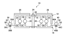
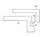
- the turning angle measuring device 10 includes an upper rotating member 12.
- the upper rotating member 12 is supported by the lower supporting member 14 so as to be able to rotate 360 degrees.
- a plurality of protrusions 16 and 18 are provided inside the upper rotating member 12 and the lower support member 14, and a ball 20 is interposed between the protrusions 16 and 18.
- the upper rotating member 12 rotates around the axis of the central axis 22 with respect to the lower supporting member 14 fixed on the floor.
- the protrusions 16 and 18 and the ball 20 realize a ball bearing function.
- the upper rotating member 12 is formed in a disk shape in appearance.
- the upper surface 12A of the upper rotating member 12 is a part in contact with the body.
- a central axis 22 serving as a center of rotation passes through the center of the upper surface of the upper rotating member 12.
- the upper surface 12A of the upper rotating member 12 is provided with a vertical axis protrusion 24 indicating the vertical axis center position and a horizontal axis protrusion 26 indicating the horizontal axis center position. For this reason, when the body is brought into contact with the upper surface 12A of the upper rotating member 12, the vertical axis projecting portion 24 and the horizontal axis projecting portion 26 are caught on the body, and the force (rotational driving) tries to rotate the upper rotating member 12 of the body. Force) is efficiently transmitted to the upper rotating member 12.
- the vertical axis projection 24 and the horizontal axis projection 26 are made of a material that is difficult to slip (a material having a high friction coefficient), so that friction generated between the body and the vertical axis projection 24 and the horizontal axis projection 26 is generated.
- Strength increases. Thereby, it is possible to prevent the body from sliding on the upper surface 12 ⁇ / b> A of the upper rotating member 12. As a result, the body and the upper rotating member 12 can be rotated integrally.
- a pointer portion 28 indicating a rotation angle is provided on the outer peripheral surface of the upper rotating member 12.
- the pointer portion 28 is provided so as to be positioned on an extension line of the vertical axis center position.
- the pointer portion 28 rotates on the rotation angle display plate 30 provided on the lower support member 14 and indicates a predetermined position of the rotation angle scale 32.
- a mounting hole 34 for mounting various attachments is formed on a part of the outer peripheral surface of the upper rotating member 12.
- a central shaft 22 passes through the center portion of the lower support member 14.
- a rotation angle display plate 30 is provided on the outer peripheral portion of the lower support member 14.
- a rotation angle scale 32 is continuously displayed on the upper surface of the rotation angle display plate 30 along the circumference of the rotation angle display plate 30.
- the rotation angle display plate 30 has a guide hole 36 formed therein.
- the guide hole 36 is continuously formed along the inner peripheral side (one round) of the rotation angle scale 32.
- An outer turning angle recording member 38 for determining the maximum outer turning angle is disposed in the guide hole 36 so as to be movable along the guide hole 36.
- an inner turning angle recording member 40 for determining the maximum inner turning angle is arranged in the guide hole 36 so as to be movable along the guide hole 36.
- the outer turning angle recording member 38 is in contact with the pointer portion 28 and indicates a predetermined position of the rotation angle scale 32, and a shaft portion provided at the bottom of the rotation angle instruction portion 38A and penetrating the guide hole 36. 38B, and a fixed portion 38C for maintaining the rotation angle instruction portion 38A stopped at a predetermined position.
- the shaft portion 38B and the fixed portion 38C are configured so that they can be screwed together like a so-called bolt and nut. For this reason, when the fixing portion 38C is tightened strongly, the rotation angle display plate 30 is eventually sandwiched between the rotation angle instruction portion 38A and the fixing portion 38C, and the outer turning angle recording member 38 becomes the predetermined angle of the rotation angle display plate 30. Fixed in position.
- the inner turning angle recording member 40 is in contact with the pointer portion 28 and indicates a predetermined position of the rotation angle scale 32, and a shaft portion provided at the bottom of the rotation angle instruction portion 40A and penetrating the guide hole 36.
- the shaft portion 40B and the fixed portion 40C are configured so that both can be screwed together like a so-called bolt and nut.
- the outer turning angle recording member 38 and the inner turning angle recording member 40 have the same configuration.
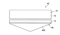
- the body balance correction device 42 includes the above-described turning angle measurement device 10 and a balance correction attachment.
- the balance correction attachment is, for example, for intentionally placing the turning angle measuring device 10 in an unstable posture, and is detachably attached to the bottom of the lower support member 14.
- a convex portion or a concave portion is provided on the balance correction attachment side
- a concave portion or a convex portion is provided on the lower support member 14 side
- the both convex portions and the concave portion are engaged.
- a “female screw part” or “female screw part” is provided on the balance correction attachment side
- a “female screw part” or “female screw part” is provided on the lower support member 14 side.
- the “female screw portion” may be assembled by screwing.
- FIG. 5 As an example of the attachment for correcting the balance, there are a curved attachment 44 shown in FIG. 5, a triangular attachment 46 shown in FIG. 6, and a pressure attachment 48 shown in FIG.
- the curved attachment 44 has a curved portion 44 ⁇ / b> A and is detachably attached to the lower support member 14.
- the curved portion 44 ⁇ / b> A is placed on the floor, and the turning angle measuring device 10 is supported by the curved attachment 44. For this reason, the turning angle measuring device 10 is in an unstable state with respect to the three axial directions.
- the triangular attachment 46 has a triangular portion 46 ⁇ / b> A in a side view and is detachably attached to the lower support member 14.
- the triangular portion 46A is placed on the floor, and the turning angle measuring device 10 is supported by the triangular attachment 46. For this reason, the turning angle measuring device 10 is in an unstable state with respect to the biaxial direction or the triaxial direction.
- the pressure type attachment 48 includes a spring fixing base portion 48 ⁇ / b> A and a plurality of coil springs 48 ⁇ / b> B provided on the spring fixing base portion 48 ⁇ / b> A.
- the plurality of coil springs 48B support the lower support member 14 from below.
- the spring fixing base portion 48A is placed on the floor, and the turning angle measuring device 10 is supported by the plurality of coil springs 48B.
- the gravity acting on the plurality of coil springs 48B differs individually due to the wobble associated with the user breaking the balance.
- the amount of elastic deformation for each coil spring 48B changes.
- the turning angle measuring device 10 becomes unstable with respect to the three axial directions.
- two turning angle measuring devices 10 are prepared.
- the right foot is placed on the upper surface 12A of the upper rotating member 12 of the right foot turning angle measuring device 10 with a posture in which the spine is straightened (the back is extended) and the knee is not bent, and the turning angle measuring device 10 for the left foot is placed.
- the left foot is placed on the upper surface 12A of the upper rotating member 12.
- the upper rotating member 12 of the turning angle measuring device 10 is removed at the same time so that both the left and right feet become “reverse-shaped” at the same time with a posture in which the spine is straight (stretched back) and the knee is not bent. Rotate (rotation in the direction of arrow ⁇ in FIG. 1). Then, the rotation angle of the outer turning of the left and right feet and the upper rotating member 12 is measured.
- the upper rotation member 12 of the turning angle measuring device 10 is simultaneously turned inward so that both the left and right feet simultaneously become “C” with a posture in which the spine is straightened (the back is stretched) and the knee is not bent. (Rotation in the direction of arrow ⁇ in FIG. 1). Then, the rotation angle of the inner turning of the left and right feet and the upper rotating member 12 is measured.
- the turning angle of the left and right feet and the upper rotating member 12 may be measured by turning either one of the left and right feet without being limited to turning both the left and right feet simultaneously.
- the outer turning angle and the inner turning angle (hip turning angle) of the hip joint can be measured.
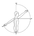
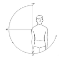
- shoulder joint flexion refers to an operation of raising the upper arm part vertically from a state where the upper arm portion is vertically lowered (a drooping state) (so-called “replacement operation before”). ).
- Typical muscles involved in the flexion of the shoulder joint include the anterior deltoid muscle, the upper pectoralis major muscle, and the incisor arm muscle.
- the range of flexion of the shoulder joint is 0 to 180 °.
- Extension of the shoulder joint refers to an operation of returning the bent upper arm portion to a suspended state as shown in FIG.
- Typical muscles involved in the extension of the shoulder joint include the latissimus dorsi, the great circular muscle, the small circular muscle, and the back of the deltoid muscle.
- the range of shoulder joint extension is 0-60 °.
- the lower support member 14 of the turning angle measuring device 10 When measuring the turning angle when the shoulder joint is bent, the lower support member 14 of the turning angle measuring device 10 is fixed to the vertical wall.
- the upper rotating member 12 When measuring the turning angle when the right shoulder joint is bent, the upper rotating member 12 is applied to the right shoulder from the right side of the right shoulder toward the front of the user. While maintaining the state in which the upper rotating member 12 is placed on the right shoulder, the upper right arm is lifted forward from a state in which the upper right arm is lowered vertically (in a suspended state). Thereby, the upper rotating member 12 rotates. By reading the turning angle of the upper rotating member 12 at this time, the turning angle when the right shoulder joint is bent can be measured.
- the upper rotating member 12 When measuring the turning angle when the right shoulder joint is extended, the upper rotating member 12 is applied to the right shoulder from the right side of the right shoulder toward the front of the user. While maintaining the state where the upper rotating member 12 is placed on the right shoulder, the upper right arm is raised rearward from a state where the upper right arm is lowered vertically (in a suspended state). As a result, the upper rotating member 12 rotates (rotates in the opposite direction to the bending). By reading the turning angle of the upper rotating member 12 at this time, the turning angle when the right shoulder joint is extended can be measured.
- the upper rotating member 12 when measuring the turning angle when the left shoulder joint is bent, the upper rotating member 12 is applied to the left shoulder from the left side of the left shoulder toward the front of the user. While maintaining the state in which the upper rotating member 12 is placed on the left shoulder, the left upper arm is lifted forward from a state in which the left upper arm portion is vertically lowered (hanging state). Thereby, the upper rotating member 12 rotates. By reading the turning angle of the upper rotating member 12 at this time, the turning angle when the left shoulder joint is bent can be measured.
- the upper rotating member 12 When measuring the turning angle when the left shoulder joint is extended, the upper rotating member 12 is applied to the left shoulder from the left side of the left shoulder toward the front of the user. While maintaining the state in which the upper rotating member 12 is placed on the left shoulder, the left upper arm is lifted rearward from a state in which the left upper arm portion is vertically lowered (a hanging state). As a result, the upper rotating member 12 rotates (rotates in the opposite direction to the bending). By reading the turning angle of the upper rotating member 12 at this time, the turning angle when the left shoulder joint is extended can be measured.
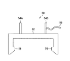
- the shoulder joint measurement attachment 50 includes an attachment main body 52 that is detachably attached to the upper rotating member 12, and a pair of parts for positioning each part of the body attached to the attachment main body 52.
- a hook portion 58 is formed on the inner peripheral side of the attachment main body 52.
- the hook portion 58 engages with the attachment hole 34 of the upper rotating member 12, so that the shoulder joint measurement attachment 50 can be easily attached to the upper rotating member 12.
- One end of the fixing band 56 is fixed to one side (positioning protrusion 54B) of the pair of positioning protrusions 54A and 54B, and the other end (tip) is the other of the pair of positioning protrusions 54A and 54B. It is configured so that it can be hooked on the side (positioning protrusion 54A).
- the upper arm When measuring the turning angle at the time of bending / extending of the shoulder joint, the upper arm is inserted between the pair of positioning projections 54A, 54B and positioned, and fixed with the fixing band 56. As a result, the upper arm portion does not detach from the positioning protrusions 54A and 54B. As described above, by using the shoulder joint measurement attachment 50, the upper arm portion can be reliably fixed to the upper rotating member 12, so that the rotational force from the upper arm portion is generated when the shoulder joint is bent or extended. It is reliably transmitted to the upper rotating member 12. As a result, the upper rotating member 12 rotates with each operation at the time of bending and extending the shoulder joint, so that the turning angle at the time of bending and extending the shoulder joint can be accurately measured.
- shoulder joint abduction refers to an operation of raising the upper arm from a state of being vertically lowered (hanging state) to a side (outside) as shown in FIG.
- Typical muscles involved in shoulder joint abduction include the supraspinatus and the middle deltoid muscle.
- the range of shoulder joint abduction is 0-180 °.
- “Shoulder joint adduction” refers to the operation of returning the above-extracted upper arm to a suspended state as shown in FIG.
- Typical muscles involved in the adduction of the shoulder joint include the latissimus dorsi, the great circular muscle, and the great pectoral muscle.
- the upper rotating member 12 When measuring the turning angle at the time of abduction of the right shoulder joint, the upper rotating member 12 is applied to the right shoulder from the front side (front side) of the right shoulder toward the front of the user. While maintaining the state in which the upper rotating member 12 is placed on the right shoulder, the upper right arm is raised from the vertically lowered state (the suspended state) to the side (outside). Thereby, the upper rotating member 12 rotates. By reading the turning angle of the upper rotating member 12 at this time, the turning angle when the right shoulder joint is abducted can be measured.
- the upper rotating member 12 When measuring the turning angle at the time of internal rotation of the right shoulder joint, the upper rotating member 12 is applied to the right shoulder from the front side (front side) of the right shoulder toward the front of the user. While maintaining the state in which the upper rotating member 12 is placed on the right shoulder, the upper right arm is raised from the vertically lowered state (the suspended state) to the side (inner side (body side)). Thereby, the upper rotating member 12 rotates. By reading the turning angle of the upper rotating member 12 at this time, it is possible to measure the turning angle at the time of internal rotation of the right shoulder joint.
- the upper rotating member 12 When measuring the turning angle at the time of abduction of the left shoulder joint, the upper rotating member 12 is applied to the left shoulder from the front side (front side) of the left shoulder toward the front of the user. While maintaining the state in which the upper rotating member 12 is placed on the left shoulder, the left upper arm is raised from the vertically lowered state (the suspended state) to the side (outside). Thereby, the upper rotating member 12 rotates. By reading the turning angle of the upper rotating member 12 at this time, the turning angle at the time of abduction of the left shoulder joint can be measured.
- the upper rotating member 12 When measuring the turning angle at the time of internal rotation of the left shoulder joint, the upper rotating member 12 is applied to the left shoulder from the front side (front side) of the left shoulder toward the front of the user. While maintaining the state in which the upper rotating member 12 is placed on the left shoulder, the left upper arm is raised from the vertically lowered state (hanging state) to the side (inner side (body side)). Thereby, the upper rotating member 12 rotates. By reading the turning angle of the upper rotating member 12 at this time, the turning angle when the left shoulder joint is turned inward can be measured.
- the turning angle of the shoulder joint during abduction / inversion can be accurately measured by using the dedicated shoulder joint measurement attachment 50 described above.
- the user's right hand is placed on the upper surface 12A of the upper rotating member 12 of the turning angle measuring device 10 in which the lower support member 14 is fixed to the vertical wall. Put the palm of your hand.
- the upper rotating member 12 is rotated while maintaining the state where the right elbow is bent at 90 degrees and the palm of the right hand is applied to the upper surface 12A of the upper rotating member 12.
- the turning angle of the ulna of the right hand can be measured.
- the palm of the user's left hand is placed on the upper surface 12A of the upper rotating member 12 of the turning angle measuring device 10 in which the lower support member 14 is fixed to the vertical wall. Hit it.
- the upper rotating member 12 is rotated while maintaining the state in which the left elbow is bent at 90 degrees and the palm of the left hand is applied to the upper surface 12A of the upper rotating member 12.
- the turning angle of the ulna of the left hand can be measured.
- the ulna measurement attachment 60 includes an attachment main body 62 that is detachably attached to the upper rotating member 12, and a grip portion 64 that is attached to the attachment main body 62 for gripping. ing.
- a hook portion 66 is formed on the inner peripheral side of the attachment main body 62.
- the hook portion 6 engages with the attachment hole 34 of the upper rotating member 12, whereby the ulna measurement attachment 60 can be attached to the upper rotating member 12.
- the user can turn the upper rotating member 12 while holding the grip portion 64.
- the turning of the ulna and the turning of the upper rotary member 12 are integrated, so that the turning angle of the ulna can be accurately measured.
- the top and the neck are rotated left and right with the upper rotating member 12 of the turning angle measuring device 10 placed on the top of the head.
- the turning angles of the cervical vertebra and the thoracolumbar region can be measured.
- the cervical vertebra and thoracolumbar region can be swung by using a dedicated attachment for the parietal region (not shown) for fixing the parietal portion to the upper rotating member 12. The angle can be measured accurately.
- the pointer portion 28 of each turning angle measuring device 10 is set to a 0 ° position.
- the right foot of the user is placed on the upper surface 12A of the upper rotating member 12 of the turning angle measuring device 10 for the right foot with a posture in which the spine is straightened (the back is stretched) and the knee is not bent.
- the left foot of the user is placed on the upper surface 12A of the upper rotating member 12 of the turning angle measuring device 10 for the left foot in such a posture that the spine is straightened (the back is straight) and the knee is not bent. At this time, each foot is placed such that the sole of the foot contacts the upper surface 12A of the upper rotating member 12.
- the user places the right foot on the upper surface 12A of the upper rotating member 12 of the turning angle measuring device 10 for the right foot and places the left foot on the upper surface 12A of the upper rotating member 12 of the turning angle measuring device 10 for the left foot. It has become.
- the left and right feet are respectively turned outward (in the direction of arrow ⁇ in FIG. 1) so that the left and right feet are in the “reverse C shape”, and then the left and right feet are in the “C” shape as viewed from the user. Each is turned inward (arrow ⁇ side in FIG. 1).
- each upper rotating member 12 of each turning angle measuring device 10 rotates around the axis of the central shaft 22 and outwardly (toward the arrow ⁇ in FIG. 1), but the pointer portion 28 is turned to each turn.
- Each upper rotating member 12 rotates to the outer turning side while pushing each outer turning angle recording member 38 of the angle measuring device 10. Accordingly, each outer turning angle recording member 38 moves along the guide hole 36 on the rotation angle display plate 30 while being pushed by the pointer portion 28.
- Each outer turning angle recording member 38 is not subjected to the pressing force from the pointer portion 28 at the position where each upper rotating member 12 of each turning angle measuring device 10 is rotated the most (the position of the maximum outer turning angle). ,Stop.
- each upper rotating member 12 of each turning angle measuring device 10 rotates around the center axis 22 and toward the inner turning side (arrow ⁇ side in FIG. 1).
- Each upper rotating member 12 rotates inwardly while pushing each inner turning angle recording member 40 of the angle measuring device 10.
- each inner turning angle recording member 40 moves along the guide hole 36 on the rotation angle display plate 30 while being pushed by the pointer portion 28.
- each inner turning angle recording member 40 does not receive the pressing force from the pointer portion 28 at the position where each upper rotating member 12 of each turning angle measuring device 10 has rotated most (the position of the maximum inner turning angle). ,Stop.
- the user can measure the maximum outer turning angle of the outer turning of the left and right feet by reading the value of the rotation angle scale 32 indicated by the rotation angle instruction section 38A of each outer turning angle recording member 38. . Further, the user can measure the maximum internal turning angle of the internal turning of both the left and right feet by reading the value of the rotational angle scale 32 indicated by the rotational angle instruction section 40A of each internal turning angle recording member 40.
- the maximum outer turning angle of the right foot outer turning and the maximum inner turning angle of the right foot inner turning are added together (the sum of the maximum turning angles of the right foot). Further, the maximum outer turning angle of the left foot outer turning and the maximum inner turning angle of the left foot inner turning are added together (the sum of the maximum turning angles of the left foot).
- the combined value of the maximum turning angle of the right foot and the combined value of the maximum turning angle of the left foot are compared.
- the foot having the larger value (the sum of the maximum turning angles) of the maximum outer turning angle of the outer turning and the maximum inner turning angle of the inner turning is determined as the shaft foot. That is, if the combined value of the maximum turning angle of the right foot> the combined value of the maximum turning angle of the left foot, the right foot becomes the shaft foot. Further, if the sum of the maximum turning angle of the right foot ⁇ the sum of the maximum turning angle of the left foot, the left foot becomes the shaft foot.
- Body balance correction method using the turning angle measuring device 10 Next, a body balance correction method using the turning angle measuring device 10 will be described. In the body balance correction method, one turning angle measuring device 10 is used.
- the shaft foot determined by the shaft foot measuring method using the turning angle measuring device 10 is placed on the upper surface 12A of the upper rotating member 12 of the turning angle measuring device 10. That is, when the right foot is determined as the axial foot, the right foot is placed on the upper surface 12 ⁇ / b> A of the upper rotating member 12 of the turning angle measuring device 10. When the left foot is determined as the axial foot, the left foot is placed on the upper surface 12 ⁇ / b> A of the upper rotating member 12 of the turning angle measuring device 10.
- the foot on the opposite side of the shaft foot side is placed on the upper surface 12A of the upper rotating member 12 of the turning angle measuring device 10 so as to float in the air. That is, when the right foot is determined to be the axial foot, the right foot is placed on the upper surface 12A of the upper rotating member 12 of the turning angle measuring device 10, and the left foot is in a state of floating in the air. Further, when the left foot is determined as the axial foot, the left foot is placed on the upper surface 12A of the upper rotating member 12 of the turning angle measuring device 10 and the right foot is floated in the air.
- the axial foot side turns outward and inward together with the upper rotating member 12 of the turning angle measuring device 10 due to a change in the user's body balance. That is, when an operation of swinging the left foot back and forth is performed, the right foot serving as the shaft foot turns outward and inward together with the upper rotating member 12 of the turning angle measuring device 10. Further, when the right foot is swung back and forth, the left foot, which is the shaft foot, turns outward and inward together with the upper rotating member 12 of the turning angle measuring device 10.
- the maximum outer turning angle and the maximum inner turning angle of the shaft foot are measured to measure the balance of the shaft foot.
- the maximum outer turning angle and the maximum inner turning angle of the shaft foot are larger (or their combined values), the balance feeling of the shaft foot is worse. In this way, variation in body balance can be measured.
- training is performed to train the sense of balance of the body by placing the shaft foot on the upper surface 12A of the upper rotating member 12 of the turning angle measuring device 10 and repeatedly performing the pendulum motion of swinging the foot opposite to the shaft foot side back and forth. Is possible. If the sense of balance of the body is improved, the maximum outer turning angle and the maximum inner turning angle of the shaft foot become small values. In this way, the balance of the body can be corrected while confirming the improvement of the sense of balance of the body each time.
- the balance of the body is not greatly lost. That is, the shaft foot is placed on the upper surface 12A of the upper rotating member 12 of the turning angle measuring device 10 and the foot opposite to the shaft foot side is swung back and forth so that the shaft foot rotates upwardly of the turning angle measuring device 10.
- the outer turning and the inner turning are performed together with the member 12, the turning angle of the upper rotating member 12 of the turning angle measuring device 10 is limited by the outer turning angle recording member 38 and the inner turning angle recording member 40.
- the ten upper rotating members 12 do not turn more than a predetermined rotation angle.
- the method of correcting the body balance by performing only the pendulum movement of the foot on the opposite side to the axial foot side has been described. It is not limited to the pendulum movements of the side legs, and the pendulum movements of both the left and right legs may be performed to correct the balance of the body.
- Body balance correction method using body balance correction device 42 Next, a body balance correction method using the body balance correction apparatus 42 will be described.
- the bending portion 44A of the bending attachment 44 is placed on the floor, and the turning angle measuring device 10 is made unstable with respect to the three axis directions. Then, the left and right feet or the shaft feet of the user are placed on the upper surface 12 ⁇ / b> A of the upper rotating member 12.
- training is performed so that the user balances the body.
- the foot on the opposite side to the shaft foot side may be swung back and forth. Thereby, the sense of balance of the user's body develops, and the balance of the body can be corrected.
- the triangular portion 46A of the triangular attachment 46 is placed on the floor, and the turning angle measuring device 10 is made unstable in the biaxial direction or the triaxial direction. Then, the left and right feet or the shaft feet of the user are placed on the upper surface 12 ⁇ / b> A of the upper rotating member 12.
- training is performed so that the user balances the body.
- the foot on the opposite side to the shaft foot side may be swung back and forth. Thereby, the sense of balance of the user's body develops, and the balance of the body can be corrected.
- a method for correcting the balance of the body using the body balance correction apparatus 42 to which the pressure type attachment 48 shown in FIG. 7 is attached will be described.
- the turning angle measuring device 10 is triaxially configured such that the spring fixing base portion 48A of the pressure attachment 48 is placed on the floor and the turning angle measuring device 10 is supported by the plurality of coil springs 48B. Make the direction unstable. Then, the left and right feet or the shaft feet of the user are placed on the upper surface 12 ⁇ / b> A of the upper rotating member 12. On such an unstable turning angle measuring apparatus 10, training is performed so that the user balances the body. In particular, when the user's shaft foot is placed on the upper surface 12A of the upper rotating member 12, the foot on the opposite side to the shaft foot side may be swung back and forth. Thereby, the sense of balance of the user's body develops, and the balance of the body can be corrected.
- the turning angle measuring device 10 stores a rotary encoder 70 that detects the rotation angle of the upper rotary member 12, and a storage unit that stores data related to the rotation angle of the upper rotary member 12 detected by the rotary encoder 70.
- ROM or RAM etc. data related to the rotation angle of the upper rotary member 12 detected by the rotary encoder 70
- data relating to the rotation angle of the upper rotary member 12 detected by the rotary encoder 70 May be printed by the printing device 74.
- the printing device 74 may be provided in the turning angle measuring device 10 or may be configured outside the turning angle measuring device 10 so that printing can be performed by a signal output from the turning angle measuring device 10. Good.
- an athlete user can train alone, so the help of a sports trainer is unnecessary, and training can be performed anytime, anywhere regardless of time and place. Can do.
- the flexibility and balance of the user's body can be enhanced.
- the turning angle measuring device 10 shown in FIGS. 1 to 4 is used as the training device 10. Since the description of the configuration of the turning angle measuring device 10 has already been given, it will be omitted.
- training methods using the turning angle measuring device 10 of FIGS. 1 to 4 as the training device 10 for example, there are so-called hip joint internal / external turning training and so-called sitting training.
- the hip joint inner / outer turning training is a training method performed by turning the hip joint inward or outward.
- a pair of turning angle measuring devices 10 are prepared. One is for the left foot and the other is for the right foot.
- the left and right feet of the person performing training are placed on each upper rotating member 12 so as to straddle the upper rotating member 12 of the turning angle measuring device 10 for the left foot and the upper rotating member 12 of the turning angle measuring device 10 for the right foot. Put it on. Thereafter, the knee of the person performing the training is straightened out and the position of the waist is fixed.
- each upper rotating member 12 is rotated inward (in the direction of arrow ⁇ in FIG. 1).
- both the left and right feet turn inward, and both the left and right feet have a “C” shape when viewed from directly above.
- each upper rotating member 12 is rotated outward (in the direction of arrow ⁇ in FIG. 1) while keeping the knee of the person performing the training straight and fixing the position of the waist.
- both the left and right feet turn outward, and both the left and right feet have a “reverse C shape” shape when viewed from directly above.
- the hip joint internal / external turning training is executed by alternately repeating the inner turning and the outer turning a predetermined number of times. By performing this training, the muscles around the hip joint can be tensioned and contracted, and as a result, the physical ability of the body can be improved.
- Performing hip joint training inside and outside improves the walking and posture of handicapped or elderly people whose activities are restricted in daily life. As a result, stiff shoulders, low back pain, knee pain and the like are improved, and the balance holding power of the body is improved.
- various arm usage can be added to the training. For example, when performing this training in a drooping state (meaning that both arms are hung down), the ability to maintain posture to balance the body using the arms can be strengthened. It is the best training for those who can't walk without grabbing.
- the arm balance function cannot be used at all.
- the posture holding ability is further required, so that it is possible to perform training that is advanced one step.
- the reverse arm is a way of assembling the arm. Becomes a signal that conveys an abnormal signal to the brain. Under such circumstances, it is an effective training method for controlling the body in a stable posture.
- the training can be performed in various postures, such as with arms extended in parallel from the shoulders, or with arms folded behind the head.
- the sitting position training is a training method in which a person who performs training sits on a chair or the like and turns the knees inward or outward. Specifically, the knee is about 90 degrees in a state where a person who performs training sits on a chair or the like. Note that “the knee is approximately 90 degrees” means that the opening angle between the knee and the knee is approximately 90 degrees.
- One foot is placed on the upper rotating member 12 and fixed by a fixing device such as a hand or a band so that the knee does not move inward or outward, and the rotating member 12 is inward (in the direction of arrow ⁇ in FIG. 1) or outward (in FIG. 1). Rotate in the direction of the middle arrow ⁇ ) to turn the knee below or inside.
- This training is performed on the left and right feet.
- the peroneal and soleus muscles can be strengthened by performing sitting training. As a result, sprains can be prevented, or arch formation of the arch portion during walking can be strengthened.
Landscapes
- Health & Medical Sciences (AREA)
- General Health & Medical Sciences (AREA)
- Physical Education & Sports Medicine (AREA)
- Orthopedic Medicine & Surgery (AREA)
- Life Sciences & Earth Sciences (AREA)
- Medical Informatics (AREA)
- Physics & Mathematics (AREA)
- Engineering & Computer Science (AREA)
- Biomedical Technology (AREA)
- Heart & Thoracic Surgery (AREA)
- Biophysics (AREA)
- Molecular Biology (AREA)
- Surgery (AREA)
- Animal Behavior & Ethology (AREA)
- Pathology (AREA)
- Public Health (AREA)
- Veterinary Medicine (AREA)
- Oral & Maxillofacial Surgery (AREA)
- Dentistry (AREA)
- Cardiology (AREA)
- Vascular Medicine (AREA)
- Measurement Of The Respiration, Hearing Ability, Form, And Blood Characteristics Of Living Organisms (AREA)
- A Measuring Device Byusing Mechanical Method (AREA)
Abstract
L'invention porte sur : un dispositif de mesure d'angle de rotation apte à augmenter la souplesse d'un corps humain ; un procédé de mesure d'angle de rotation ; un procédé de mesure de pied de pivot apte à déterminer un pied de pivot ; un dispositif d'entraînement pour renforcer la force musculaire (ou le muscle) de chaque partie du corps humain ; et un procédé d'entraînement. La présente invention comporte : un élément de rotation supérieur (12) tournant autour de l'axe d'un arbre central, un corps humain étant en contact avec l'élément de rotation supérieur ; un élément de support inférieur (14) pour supporter l'élément de rotation supérieur (12), de telle sorte que l'élément de rotation supérieur (12) peut tourner autour de l'axe de l'arbre central (22) ; un élément d'échelle d'angle de rotation (30) comportant une échelle d'angle de rotation (32) pour indiquer l'angle de rotation de l'élément de rotation supérieur (12) ; et un élément de pointage d'angle de rotation (28) tournant conjointement avec la rotation de l'élément de rotation supérieur (12) autour de l'axe de l'arbre central (22) et pointant vers une position prédéterminée sur l'échelle d'angle de rotation (32).
Applications Claiming Priority (2)
| Application Number | Priority Date | Filing Date | Title |
|---|---|---|---|
| JP2011026416A JP2014076068A (ja) | 2011-02-09 | 2011-02-09 | 旋回角度測定装置、旋回角度測定方法及び軸足測定方法 |
| JP2011-026416 | 2011-02-09 |
Publications (1)
| Publication Number | Publication Date |
|---|---|
| WO2012108422A1 true WO2012108422A1 (fr) | 2012-08-16 |
Family
ID=46638635
Family Applications (1)
| Application Number | Title | Priority Date | Filing Date |
|---|---|---|---|
| PCT/JP2012/052726 WO2012108422A1 (fr) | 2011-02-09 | 2012-02-07 | Dispositif de mesure d'angle de rotation, procédé de mesure d'angle de rotation, procédé de mesure de pied de pivot, dispositif d'entraînement et procédé d'entraînement |
Country Status (2)
| Country | Link |
|---|---|
| JP (1) | JP2014076068A (fr) |
| WO (1) | WO2012108422A1 (fr) |
Cited By (1)
| Publication number | Priority date | Publication date | Assignee | Title |
|---|---|---|---|---|
| US11262175B2 (en) | 2017-02-05 | 2022-03-01 | Progressivehealth Companies, Llc | Method and apparatus for measuring an individual's abtility to perform a varying range of barrier reaches |
Citations (6)
| Publication number | Priority date | Publication date | Assignee | Title |
|---|---|---|---|---|
| JPS49145766U (fr) * | 1973-04-13 | 1974-12-16 | ||
| JPH07194758A (ja) * | 1993-12-29 | 1995-08-01 | Noboru Soejima | バインディング取り付け位置決定方法ならびにその装置 |
| JPH0857087A (ja) * | 1994-08-17 | 1996-03-05 | Noboru Soejima | ラケットグリップ位置検出装置ならびにグリップ表示部を具備するラケット |
| JP2002074082A (ja) * | 2000-08-30 | 2002-03-12 | Noboru Soejima | 運動用具の選定方法 |
| JP2002136632A (ja) * | 2000-08-22 | 2002-05-14 | Matsushita Seiko Co Ltd | スタンス設定装置 |
| JP2009268590A (ja) * | 2008-05-01 | 2009-11-19 | Koji Torii | 捻れ計測装置及びそれを用いた捻れ測定方法 |
-
2011
- 2011-02-09 JP JP2011026416A patent/JP2014076068A/ja not_active Withdrawn
-
2012
- 2012-02-07 WO PCT/JP2012/052726 patent/WO2012108422A1/fr active Application Filing
Patent Citations (6)
| Publication number | Priority date | Publication date | Assignee | Title |
|---|---|---|---|---|
| JPS49145766U (fr) * | 1973-04-13 | 1974-12-16 | ||
| JPH07194758A (ja) * | 1993-12-29 | 1995-08-01 | Noboru Soejima | バインディング取り付け位置決定方法ならびにその装置 |
| JPH0857087A (ja) * | 1994-08-17 | 1996-03-05 | Noboru Soejima | ラケットグリップ位置検出装置ならびにグリップ表示部を具備するラケット |
| JP2002136632A (ja) * | 2000-08-22 | 2002-05-14 | Matsushita Seiko Co Ltd | スタンス設定装置 |
| JP2002074082A (ja) * | 2000-08-30 | 2002-03-12 | Noboru Soejima | 運動用具の選定方法 |
| JP2009268590A (ja) * | 2008-05-01 | 2009-11-19 | Koji Torii | 捻れ計測装置及びそれを用いた捻れ測定方法 |
Cited By (1)
| Publication number | Priority date | Publication date | Assignee | Title |
|---|---|---|---|---|
| US11262175B2 (en) | 2017-02-05 | 2022-03-01 | Progressivehealth Companies, Llc | Method and apparatus for measuring an individual's abtility to perform a varying range of barrier reaches |
Also Published As
| Publication number | Publication date |
|---|---|
| JP2014076068A (ja) | 2014-05-01 |
Similar Documents
| Publication | Publication Date | Title |
|---|---|---|
| US7951054B2 (en) | Rehabilitation and exercise apparatus | |
| US7717834B2 (en) | Therapeutic shoulder apparatus | |
| JPH09501575A (ja) | 自立回旋筋腱板発育装置 | |
| RU2018140482A (ru) | Тренажерное устройство для мышц брюшного пресса и корпуса | |
| US20070219068A1 (en) | Method and apparatus for controlling repetitive movements | |
| KR101044094B1 (ko) | 하체 근력강화 운동기구 | |
| US20050079964A1 (en) | Spherical back exerciser apparatus | |
| US20150265872A1 (en) | Squat Exercising | |
| Kobesova et al. | Dynamic Neuromuscular Stabilization: Exercises based on developmental kinesiology models | |
| KR200436589Y1 (ko) | 다리 스트레칭 기구 | |
| US20090111657A1 (en) | Rehabilitation and exercise apparatus | |
| US20150258368A1 (en) | Method and Portable Apparatus, With Adjustable Resistance, for Exercising The Upper Extremities | |
| US20110137215A1 (en) | Apparatus and Method for Knee Rehabilitation | |
| US20100311024A1 (en) | Suspended exercise apparatus and method of use | |
| JP2005342177A (ja) | 腹部腰部諸筋トレーニング器具 | |
| WO2012108422A1 (fr) | Dispositif de mesure d'angle de rotation, procédé de mesure d'angle de rotation, procédé de mesure de pied de pivot, dispositif d'entraînement et procédé d'entraînement | |
| KR20190043120A (ko) | 무릎과 발목 관절을 보호하며 다리 상부와 힙을 운동시키는 방법 및 장치 | |
| JP6106378B2 (ja) | トレーニング装置及びトレーニング方法 | |
| CN210845155U (zh) | 一种骨盆活动训练器 | |
| CN109821200B (zh) | 肩部锻炼装置 | |
| CN210078750U (zh) | 一种肩部锻炼装置 | |
| JP4292520B2 (ja) | トレーニング器具 | |
| JP4547360B2 (ja) | トレーニング器具 | |
| US9616275B1 (en) | Ankle strengthening exercise device | |
| CN210873941U (zh) | 一种新型老年心血管病上肢锻炼恢复装置 |
Legal Events
| Date | Code | Title | Description |
|---|---|---|---|
| 121 | Ep: the epo has been informed by wipo that ep was designated in this application |
Ref document number: 12744654 Country of ref document: EP Kind code of ref document: A1 |
|
| NENP | Non-entry into the national phase |
Ref country code: DE |
|
| 122 | Ep: pct application non-entry in european phase |
Ref document number: 12744654 Country of ref document: EP Kind code of ref document: A1 |
|
| NENP | Non-entry into the national phase |
Ref country code: JP |