WO2012108422A1 - Rotation angle measurement device, rotation angle measurement method, pivot foot measurement method, training device, and training method - Google Patents
Rotation angle measurement device, rotation angle measurement method, pivot foot measurement method, training device, and training method Download PDFInfo
- Publication number
- WO2012108422A1 WO2012108422A1 PCT/JP2012/052726 JP2012052726W WO2012108422A1 WO 2012108422 A1 WO2012108422 A1 WO 2012108422A1 JP 2012052726 W JP2012052726 W JP 2012052726W WO 2012108422 A1 WO2012108422 A1 WO 2012108422A1
- Authority
- WO
- WIPO (PCT)
- Prior art keywords
- rotation angle
- rotation
- turning angle
- rotating member
- turning
- Prior art date
Links
Images


Classifications
-
- A—HUMAN NECESSITIES
- A61—MEDICAL OR VETERINARY SCIENCE; HYGIENE
- A61B—DIAGNOSIS; SURGERY; IDENTIFICATION
- A61B5/00—Measuring for diagnostic purposes; Identification of persons
- A61B5/103—Detecting, measuring or recording devices for testing the shape, pattern, colour, size or movement of the body or parts thereof, for diagnostic purposes
- A61B5/107—Measuring physical dimensions, e.g. size of the entire body or parts thereof
- A61B5/1071—Measuring physical dimensions, e.g. size of the entire body or parts thereof measuring angles, e.g. using goniometers
-
- A—HUMAN NECESSITIES
- A63—SPORTS; GAMES; AMUSEMENTS
- A63B—APPARATUS FOR PHYSICAL TRAINING, GYMNASTICS, SWIMMING, CLIMBING, OR FENCING; BALL GAMES; TRAINING EQUIPMENT
- A63B22/00—Exercising apparatus specially adapted for conditioning the cardio-vascular system, for training agility or co-ordination of movements
- A63B22/14—Platforms for reciprocating rotating motion about a vertical axis, e.g. axis through the middle of the platform
-
- A—HUMAN NECESSITIES
- A63—SPORTS; GAMES; AMUSEMENTS
- A63B—APPARATUS FOR PHYSICAL TRAINING, GYMNASTICS, SWIMMING, CLIMBING, OR FENCING; BALL GAMES; TRAINING EQUIPMENT
- A63B23/00—Exercising apparatus specially adapted for particular parts of the body
- A63B23/035—Exercising apparatus specially adapted for particular parts of the body for limbs, i.e. upper or lower limbs, e.g. simultaneously
- A63B23/03516—For both arms together or both legs together; Aspects related to the co-ordination between right and left side limbs of a user
- A63B23/03533—With separate means driven by each limb, i.e. performing different movements
- A63B23/03541—Moving independently from each other
-
- A—HUMAN NECESSITIES
- A63—SPORTS; GAMES; AMUSEMENTS
- A63B—APPARATUS FOR PHYSICAL TRAINING, GYMNASTICS, SWIMMING, CLIMBING, OR FENCING; BALL GAMES; TRAINING EQUIPMENT
- A63B23/00—Exercising apparatus specially adapted for particular parts of the body
- A63B23/035—Exercising apparatus specially adapted for particular parts of the body for limbs, i.e. upper or lower limbs, e.g. simultaneously
- A63B23/04—Exercising apparatus specially adapted for particular parts of the body for limbs, i.e. upper or lower limbs, e.g. simultaneously for lower limbs
- A63B23/0482—Exercising apparatus specially adapted for particular parts of the body for limbs, i.e. upper or lower limbs, e.g. simultaneously for lower limbs primarily by articulating the hip joints
-
- A—HUMAN NECESSITIES
- A63—SPORTS; GAMES; AMUSEMENTS
- A63B—APPARATUS FOR PHYSICAL TRAINING, GYMNASTICS, SWIMMING, CLIMBING, OR FENCING; BALL GAMES; TRAINING EQUIPMENT
- A63B26/00—Exercising apparatus not covered by groups A63B1/00 - A63B25/00
- A63B26/003—Exercising apparatus not covered by groups A63B1/00 - A63B25/00 for improving balance or equilibrium
-
- A—HUMAN NECESSITIES
- A63—SPORTS; GAMES; AMUSEMENTS
- A63B—APPARATUS FOR PHYSICAL TRAINING, GYMNASTICS, SWIMMING, CLIMBING, OR FENCING; BALL GAMES; TRAINING EQUIPMENT
- A63B23/00—Exercising apparatus specially adapted for particular parts of the body
- A63B2023/003—Exercising apparatus specially adapted for particular parts of the body by torsion of the body part around its longitudinal axis
-
- A—HUMAN NECESSITIES
- A63—SPORTS; GAMES; AMUSEMENTS
- A63B—APPARATUS FOR PHYSICAL TRAINING, GYMNASTICS, SWIMMING, CLIMBING, OR FENCING; BALL GAMES; TRAINING EQUIPMENT
- A63B2208/00—Characteristics or parameters related to the user or player
- A63B2208/02—Characteristics or parameters related to the user or player posture
- A63B2208/0228—Sitting on the buttocks
-
- A—HUMAN NECESSITIES
- A63—SPORTS; GAMES; AMUSEMENTS
- A63B—APPARATUS FOR PHYSICAL TRAINING, GYMNASTICS, SWIMMING, CLIMBING, OR FENCING; BALL GAMES; TRAINING EQUIPMENT
- A63B2220/00—Measuring of physical parameters relating to sporting activity
- A63B2220/20—Distances or displacements
- A63B2220/24—Angular displacement
Definitions
- the present invention provides, for example, a turning angle measuring device and a turning angle measuring method for measuring a turning angle of each part of the body, a shaft foot measuring method for determining a pivot foot, and a muscle force (or muscle) of each part of the body.
- the present invention relates to a training apparatus and a training method.
- the sports trainer supports it by supporting athletes' flexible exercises and the like.
- the present invention provides a turning angle measuring device, a turning angle measuring method, and a pivot foot measuring method capable of determining a pivot foot, which can increase body flexibility. For the purpose.
- Another object of the present invention is to provide a training device and a training method for strengthening the muscular strength (or muscle) of each part of the body.
- a first aspect of the invention is a turning angle measuring device for measuring a turning angle of a body, the rotating member rotating around the axis of the central axis in contact with the body, and the rotating member around the axis of the central axis
- a rotation angle scale member having a rotation angle scale for indicating a rotation angle of the rotation member, and a rotation angle rotated by rotating around a central axis of the rotation member.
- a rotation angle indicating member indicating a predetermined position of the scale.
- the support member is pressed by the rotation angle indicating member during rotation around the central axis of the rotation member and moves on the rotation angle scale member, and a predetermined position of the rotation angle scale. It is preferable to have a rotation angle recording member that stops at a step and a guide hole that allows the rotation angle recording member to move.
- a fixing member for restricting the rotation of the rotating member beyond a predetermined rotation angle is provided.
- the support member is pressed by the rotation angle indicating member during rotation around the central axis of the rotation member and moves on the rotation angle scale member, and a predetermined position of the rotation angle scale. It is preferable that the rotation angle recording member stops at a position and a guide hole that allows movement of the rotation angle recording member, and the fixing member is the rotation angle recording member.
- a rotation angle detection unit that detects the rotation angle of the rotation member
- a storage unit that stores data related to the rotation angle of the rotation member detected by the rotation angle detection unit.
- a second invention is a turning angle measuring method for measuring a turning angle of the body using each of the turning angle measuring devices described above, wherein either one of the left and right legs is attached to the rotating member with a posture in which the back is stretched and the knee is not bent. The rotating member is rotated together with the foot, and the turning angle of the hip joint is measured.
- the turning angle measuring device includes: a rotation angle detection unit that detects a rotation angle of the rotation member; and a storage unit that stores data related to the rotation angle of the rotation member detected by the rotation angle detection unit.
- the printing unit prints data related to the rotation angle of the rotating member detected by the rotation angle detection unit.
- 3rd invention is a turning angle measuring method which measures a turning angle of the body using each said turning angle measuring device, Comprising: The said rotating member in the state which made the left or right shoulder contact the said rotating member Rotate with the shoulder, and measure the turning angle during flexion, extension, abduction, adduction, external rotation, and internal rotation of the shoulder joint.
- the turning angle measuring device includes: a rotation angle detection unit that detects a rotation angle of the rotation member; and a storage unit that stores data related to the rotation angle of the rotation member detected by the rotation angle detection unit.
- the printing unit prints data related to the rotation angle of the rotating member detected by the rotation angle detection unit.
- a fourth invention is a turning angle measurement method for measuring a turning angle of a body using each of the turning angle measuring devices described above, wherein the rotating member is placed in a state in which either the left or right hand is in contact with the rotating member. Rotate with hand to measure ulnar swivel angle.
- the turning angle measuring device includes: a rotation angle detection unit that detects a rotation angle of the rotation member; and a storage unit that stores data related to the rotation angle of the rotation member detected by the rotation angle detection unit.
- the printing unit prints data related to the rotation angle of the rotating member detected by the rotation angle detection unit.
- the measurer's hand is fixed to the rotating member using an attachment and the rotating member is rotated.
- 5th invention is a turning angle measuring method which measures a turning angle of the body using each said turning angle measuring device, Comprising: With the said rotation member mounted on the top of a head, the said rotation member was put together with the top and the neck. Rotate and measure swivel angles of cervical spine and thoracolumbar region.
- the turning angle measuring device includes: a rotation angle detection unit that detects a rotation angle of the rotation member; and a storage unit that stores data related to the rotation angle of the rotation member detected by the rotation angle detection unit.
- the printing unit prints data related to the rotation angle of the rotating member detected by the rotation angle detection unit.
- a sixth aspect of the invention is an axial foot measuring method for determining an axial foot using each of the turning angle measuring devices described above, wherein either the left or right foot is placed on the rotating member in a posture that does not extend the back muscles and bend the knee.
- the rotating member is turned outward and inward with the foot, and the maximum outer turning angle of the outer turning and the maximum inner turning angle of the inner turning are measured, and the maximum outer turning angle of the outer turning and the maximum inner turning angle of the inner turning are measured.
- the turning angles are added together, and the left and right feet are determined as the shaft foot with the larger value obtained by adding the maximum outer turning angle of the outer turning and the maximum inner turning angle of the inner turning.
- a seventh aspect of the present invention is a training apparatus for training a body, and a rotating member that rotates about a central axis in contact with the body, and supports the rotating member so as to be rotatable about the central axis.
- a rotation angle scale member having a rotation angle scale for indicating a rotation angle of the rotation member, and a predetermined position of the rotation angle scale by rotating together with the rotation around the central axis of the rotation member A rotation angle indicating member.
- the support member is pressed by the rotation angle indicating member during rotation around the central axis of the rotation member and moves on the rotation angle scale member, and a predetermined position of the rotation angle scale. It is preferable to have a rotation angle recording member that stops at a step and a guide hole that allows the rotation angle recording member to move.
- a fixing member for restricting the rotation of the rotating member beyond a predetermined rotation angle is provided.
- the support member is pressed by the rotation angle indicating member during rotation around the central axis of the rotation member and moves on the rotation angle scale member, and a predetermined position of the rotation angle scale. It is preferable that the rotation angle recording member stops at a position and a guide hole that allows movement of the rotation angle recording member, and the fixing member is the rotation angle recording member.
- An eighth invention is a training method using each of the training devices described above, using a pair of the training devices, placing both feet on each rotating member so as to straddle each rotating member, extending the knee straight, In a state where the position of the waist is fixed, the rotating members are rotated inwardly or outwardly to turn both feet inwardly or outwardly.
- a ninth invention is a training method using the above-described training apparatus, wherein the knee is moved inward or outward by sitting on a chair or the like and placing one foot on the rotating member at a position where the knee is approximately 90 degrees. It fixes so that it may not exist, and the said rotation member is rotated inside or outside, and the knee is made to turn inside or outside.
- the flexibility of the body can be increased.
- the muscular strength (or muscle) of each part of the body can be strengthened.
- a turning angle measuring device, a turning angle measuring method, and a pivot foot measuring method according to a first embodiment of the present invention will be described with reference to the drawings.
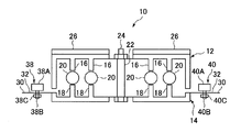
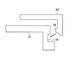
- the turning angle measuring device 10 includes an upper rotating member 12.
- the upper rotating member 12 is supported by the lower supporting member 14 so as to be able to rotate 360 degrees.
- a plurality of protrusions 16 and 18 are provided inside the upper rotating member 12 and the lower support member 14, and a ball 20 is interposed between the protrusions 16 and 18.
- the upper rotating member 12 rotates around the axis of the central axis 22 with respect to the lower supporting member 14 fixed on the floor.
- the protrusions 16 and 18 and the ball 20 realize a ball bearing function.
- the upper rotating member 12 is formed in a disk shape in appearance.
- the upper surface 12A of the upper rotating member 12 is a part in contact with the body.
- a central axis 22 serving as a center of rotation passes through the center of the upper surface of the upper rotating member 12.
- the upper surface 12A of the upper rotating member 12 is provided with a vertical axis protrusion 24 indicating the vertical axis center position and a horizontal axis protrusion 26 indicating the horizontal axis center position. For this reason, when the body is brought into contact with the upper surface 12A of the upper rotating member 12, the vertical axis projecting portion 24 and the horizontal axis projecting portion 26 are caught on the body, and the force (rotational driving) tries to rotate the upper rotating member 12 of the body. Force) is efficiently transmitted to the upper rotating member 12.
- the vertical axis projection 24 and the horizontal axis projection 26 are made of a material that is difficult to slip (a material having a high friction coefficient), so that friction generated between the body and the vertical axis projection 24 and the horizontal axis projection 26 is generated.
- Strength increases. Thereby, it is possible to prevent the body from sliding on the upper surface 12 ⁇ / b> A of the upper rotating member 12. As a result, the body and the upper rotating member 12 can be rotated integrally.
- a pointer portion 28 indicating a rotation angle is provided on the outer peripheral surface of the upper rotating member 12.
- the pointer portion 28 is provided so as to be positioned on an extension line of the vertical axis center position.
- the pointer portion 28 rotates on the rotation angle display plate 30 provided on the lower support member 14 and indicates a predetermined position of the rotation angle scale 32.
- a mounting hole 34 for mounting various attachments is formed on a part of the outer peripheral surface of the upper rotating member 12.
- a central shaft 22 passes through the center portion of the lower support member 14.
- a rotation angle display plate 30 is provided on the outer peripheral portion of the lower support member 14.
- a rotation angle scale 32 is continuously displayed on the upper surface of the rotation angle display plate 30 along the circumference of the rotation angle display plate 30.
- the rotation angle display plate 30 has a guide hole 36 formed therein.
- the guide hole 36 is continuously formed along the inner peripheral side (one round) of the rotation angle scale 32.
- An outer turning angle recording member 38 for determining the maximum outer turning angle is disposed in the guide hole 36 so as to be movable along the guide hole 36.
- an inner turning angle recording member 40 for determining the maximum inner turning angle is arranged in the guide hole 36 so as to be movable along the guide hole 36.
- the outer turning angle recording member 38 is in contact with the pointer portion 28 and indicates a predetermined position of the rotation angle scale 32, and a shaft portion provided at the bottom of the rotation angle instruction portion 38A and penetrating the guide hole 36. 38B, and a fixed portion 38C for maintaining the rotation angle instruction portion 38A stopped at a predetermined position.
- the shaft portion 38B and the fixed portion 38C are configured so that they can be screwed together like a so-called bolt and nut. For this reason, when the fixing portion 38C is tightened strongly, the rotation angle display plate 30 is eventually sandwiched between the rotation angle instruction portion 38A and the fixing portion 38C, and the outer turning angle recording member 38 becomes the predetermined angle of the rotation angle display plate 30. Fixed in position.
- the inner turning angle recording member 40 is in contact with the pointer portion 28 and indicates a predetermined position of the rotation angle scale 32, and a shaft portion provided at the bottom of the rotation angle instruction portion 40A and penetrating the guide hole 36.
- the shaft portion 40B and the fixed portion 40C are configured so that both can be screwed together like a so-called bolt and nut.
- the outer turning angle recording member 38 and the inner turning angle recording member 40 have the same configuration.
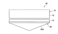
- the body balance correction device 42 includes the above-described turning angle measurement device 10 and a balance correction attachment.
- the balance correction attachment is, for example, for intentionally placing the turning angle measuring device 10 in an unstable posture, and is detachably attached to the bottom of the lower support member 14.
- a convex portion or a concave portion is provided on the balance correction attachment side
- a concave portion or a convex portion is provided on the lower support member 14 side
- the both convex portions and the concave portion are engaged.
- a “female screw part” or “female screw part” is provided on the balance correction attachment side
- a “female screw part” or “female screw part” is provided on the lower support member 14 side.
- the “female screw portion” may be assembled by screwing.
- FIG. 5 As an example of the attachment for correcting the balance, there are a curved attachment 44 shown in FIG. 5, a triangular attachment 46 shown in FIG. 6, and a pressure attachment 48 shown in FIG.
- the curved attachment 44 has a curved portion 44 ⁇ / b> A and is detachably attached to the lower support member 14.
- the curved portion 44 ⁇ / b> A is placed on the floor, and the turning angle measuring device 10 is supported by the curved attachment 44. For this reason, the turning angle measuring device 10 is in an unstable state with respect to the three axial directions.
- the triangular attachment 46 has a triangular portion 46 ⁇ / b> A in a side view and is detachably attached to the lower support member 14.
- the triangular portion 46A is placed on the floor, and the turning angle measuring device 10 is supported by the triangular attachment 46. For this reason, the turning angle measuring device 10 is in an unstable state with respect to the biaxial direction or the triaxial direction.
- the pressure type attachment 48 includes a spring fixing base portion 48 ⁇ / b> A and a plurality of coil springs 48 ⁇ / b> B provided on the spring fixing base portion 48 ⁇ / b> A.
- the plurality of coil springs 48B support the lower support member 14 from below.
- the spring fixing base portion 48A is placed on the floor, and the turning angle measuring device 10 is supported by the plurality of coil springs 48B.
- the gravity acting on the plurality of coil springs 48B differs individually due to the wobble associated with the user breaking the balance.
- the amount of elastic deformation for each coil spring 48B changes.
- the turning angle measuring device 10 becomes unstable with respect to the three axial directions.
- two turning angle measuring devices 10 are prepared.
- the right foot is placed on the upper surface 12A of the upper rotating member 12 of the right foot turning angle measuring device 10 with a posture in which the spine is straightened (the back is extended) and the knee is not bent, and the turning angle measuring device 10 for the left foot is placed.
- the left foot is placed on the upper surface 12A of the upper rotating member 12.
- the upper rotating member 12 of the turning angle measuring device 10 is removed at the same time so that both the left and right feet become “reverse-shaped” at the same time with a posture in which the spine is straight (stretched back) and the knee is not bent. Rotate (rotation in the direction of arrow ⁇ in FIG. 1). Then, the rotation angle of the outer turning of the left and right feet and the upper rotating member 12 is measured.
- the upper rotation member 12 of the turning angle measuring device 10 is simultaneously turned inward so that both the left and right feet simultaneously become “C” with a posture in which the spine is straightened (the back is stretched) and the knee is not bent. (Rotation in the direction of arrow ⁇ in FIG. 1). Then, the rotation angle of the inner turning of the left and right feet and the upper rotating member 12 is measured.
- the turning angle of the left and right feet and the upper rotating member 12 may be measured by turning either one of the left and right feet without being limited to turning both the left and right feet simultaneously.
- the outer turning angle and the inner turning angle (hip turning angle) of the hip joint can be measured.
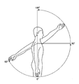
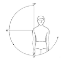
- shoulder joint flexion refers to an operation of raising the upper arm part vertically from a state where the upper arm portion is vertically lowered (a drooping state) (so-called “replacement operation before”). ).
- Typical muscles involved in the flexion of the shoulder joint include the anterior deltoid muscle, the upper pectoralis major muscle, and the incisor arm muscle.
- the range of flexion of the shoulder joint is 0 to 180 °.
- Extension of the shoulder joint refers to an operation of returning the bent upper arm portion to a suspended state as shown in FIG.
- Typical muscles involved in the extension of the shoulder joint include the latissimus dorsi, the great circular muscle, the small circular muscle, and the back of the deltoid muscle.
- the range of shoulder joint extension is 0-60 °.
- the lower support member 14 of the turning angle measuring device 10 When measuring the turning angle when the shoulder joint is bent, the lower support member 14 of the turning angle measuring device 10 is fixed to the vertical wall.
- the upper rotating member 12 When measuring the turning angle when the right shoulder joint is bent, the upper rotating member 12 is applied to the right shoulder from the right side of the right shoulder toward the front of the user. While maintaining the state in which the upper rotating member 12 is placed on the right shoulder, the upper right arm is lifted forward from a state in which the upper right arm is lowered vertically (in a suspended state). Thereby, the upper rotating member 12 rotates. By reading the turning angle of the upper rotating member 12 at this time, the turning angle when the right shoulder joint is bent can be measured.
- the upper rotating member 12 When measuring the turning angle when the right shoulder joint is extended, the upper rotating member 12 is applied to the right shoulder from the right side of the right shoulder toward the front of the user. While maintaining the state where the upper rotating member 12 is placed on the right shoulder, the upper right arm is raised rearward from a state where the upper right arm is lowered vertically (in a suspended state). As a result, the upper rotating member 12 rotates (rotates in the opposite direction to the bending). By reading the turning angle of the upper rotating member 12 at this time, the turning angle when the right shoulder joint is extended can be measured.
- the upper rotating member 12 when measuring the turning angle when the left shoulder joint is bent, the upper rotating member 12 is applied to the left shoulder from the left side of the left shoulder toward the front of the user. While maintaining the state in which the upper rotating member 12 is placed on the left shoulder, the left upper arm is lifted forward from a state in which the left upper arm portion is vertically lowered (hanging state). Thereby, the upper rotating member 12 rotates. By reading the turning angle of the upper rotating member 12 at this time, the turning angle when the left shoulder joint is bent can be measured.
- the upper rotating member 12 When measuring the turning angle when the left shoulder joint is extended, the upper rotating member 12 is applied to the left shoulder from the left side of the left shoulder toward the front of the user. While maintaining the state in which the upper rotating member 12 is placed on the left shoulder, the left upper arm is lifted rearward from a state in which the left upper arm portion is vertically lowered (a hanging state). As a result, the upper rotating member 12 rotates (rotates in the opposite direction to the bending). By reading the turning angle of the upper rotating member 12 at this time, the turning angle when the left shoulder joint is extended can be measured.
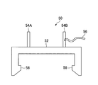
- the shoulder joint measurement attachment 50 includes an attachment main body 52 that is detachably attached to the upper rotating member 12, and a pair of parts for positioning each part of the body attached to the attachment main body 52.
- a hook portion 58 is formed on the inner peripheral side of the attachment main body 52.
- the hook portion 58 engages with the attachment hole 34 of the upper rotating member 12, so that the shoulder joint measurement attachment 50 can be easily attached to the upper rotating member 12.
- One end of the fixing band 56 is fixed to one side (positioning protrusion 54B) of the pair of positioning protrusions 54A and 54B, and the other end (tip) is the other of the pair of positioning protrusions 54A and 54B. It is configured so that it can be hooked on the side (positioning protrusion 54A).
- the upper arm When measuring the turning angle at the time of bending / extending of the shoulder joint, the upper arm is inserted between the pair of positioning projections 54A, 54B and positioned, and fixed with the fixing band 56. As a result, the upper arm portion does not detach from the positioning protrusions 54A and 54B. As described above, by using the shoulder joint measurement attachment 50, the upper arm portion can be reliably fixed to the upper rotating member 12, so that the rotational force from the upper arm portion is generated when the shoulder joint is bent or extended. It is reliably transmitted to the upper rotating member 12. As a result, the upper rotating member 12 rotates with each operation at the time of bending and extending the shoulder joint, so that the turning angle at the time of bending and extending the shoulder joint can be accurately measured.
- shoulder joint abduction refers to an operation of raising the upper arm from a state of being vertically lowered (hanging state) to a side (outside) as shown in FIG.
- Typical muscles involved in shoulder joint abduction include the supraspinatus and the middle deltoid muscle.
- the range of shoulder joint abduction is 0-180 °.
- “Shoulder joint adduction” refers to the operation of returning the above-extracted upper arm to a suspended state as shown in FIG.
- Typical muscles involved in the adduction of the shoulder joint include the latissimus dorsi, the great circular muscle, and the great pectoral muscle.
- the upper rotating member 12 When measuring the turning angle at the time of abduction of the right shoulder joint, the upper rotating member 12 is applied to the right shoulder from the front side (front side) of the right shoulder toward the front of the user. While maintaining the state in which the upper rotating member 12 is placed on the right shoulder, the upper right arm is raised from the vertically lowered state (the suspended state) to the side (outside). Thereby, the upper rotating member 12 rotates. By reading the turning angle of the upper rotating member 12 at this time, the turning angle when the right shoulder joint is abducted can be measured.
- the upper rotating member 12 When measuring the turning angle at the time of internal rotation of the right shoulder joint, the upper rotating member 12 is applied to the right shoulder from the front side (front side) of the right shoulder toward the front of the user. While maintaining the state in which the upper rotating member 12 is placed on the right shoulder, the upper right arm is raised from the vertically lowered state (the suspended state) to the side (inner side (body side)). Thereby, the upper rotating member 12 rotates. By reading the turning angle of the upper rotating member 12 at this time, it is possible to measure the turning angle at the time of internal rotation of the right shoulder joint.
- the upper rotating member 12 When measuring the turning angle at the time of abduction of the left shoulder joint, the upper rotating member 12 is applied to the left shoulder from the front side (front side) of the left shoulder toward the front of the user. While maintaining the state in which the upper rotating member 12 is placed on the left shoulder, the left upper arm is raised from the vertically lowered state (the suspended state) to the side (outside). Thereby, the upper rotating member 12 rotates. By reading the turning angle of the upper rotating member 12 at this time, the turning angle at the time of abduction of the left shoulder joint can be measured.
- the upper rotating member 12 When measuring the turning angle at the time of internal rotation of the left shoulder joint, the upper rotating member 12 is applied to the left shoulder from the front side (front side) of the left shoulder toward the front of the user. While maintaining the state in which the upper rotating member 12 is placed on the left shoulder, the left upper arm is raised from the vertically lowered state (hanging state) to the side (inner side (body side)). Thereby, the upper rotating member 12 rotates. By reading the turning angle of the upper rotating member 12 at this time, the turning angle when the left shoulder joint is turned inward can be measured.
- the turning angle of the shoulder joint during abduction / inversion can be accurately measured by using the dedicated shoulder joint measurement attachment 50 described above.
- the user's right hand is placed on the upper surface 12A of the upper rotating member 12 of the turning angle measuring device 10 in which the lower support member 14 is fixed to the vertical wall. Put the palm of your hand.
- the upper rotating member 12 is rotated while maintaining the state where the right elbow is bent at 90 degrees and the palm of the right hand is applied to the upper surface 12A of the upper rotating member 12.
- the turning angle of the ulna of the right hand can be measured.
- the palm of the user's left hand is placed on the upper surface 12A of the upper rotating member 12 of the turning angle measuring device 10 in which the lower support member 14 is fixed to the vertical wall. Hit it.
- the upper rotating member 12 is rotated while maintaining the state in which the left elbow is bent at 90 degrees and the palm of the left hand is applied to the upper surface 12A of the upper rotating member 12.
- the turning angle of the ulna of the left hand can be measured.
- the ulna measurement attachment 60 includes an attachment main body 62 that is detachably attached to the upper rotating member 12, and a grip portion 64 that is attached to the attachment main body 62 for gripping. ing.
- a hook portion 66 is formed on the inner peripheral side of the attachment main body 62.
- the hook portion 6 engages with the attachment hole 34 of the upper rotating member 12, whereby the ulna measurement attachment 60 can be attached to the upper rotating member 12.
- the user can turn the upper rotating member 12 while holding the grip portion 64.
- the turning of the ulna and the turning of the upper rotary member 12 are integrated, so that the turning angle of the ulna can be accurately measured.
- the top and the neck are rotated left and right with the upper rotating member 12 of the turning angle measuring device 10 placed on the top of the head.
- the turning angles of the cervical vertebra and the thoracolumbar region can be measured.
- the cervical vertebra and thoracolumbar region can be swung by using a dedicated attachment for the parietal region (not shown) for fixing the parietal portion to the upper rotating member 12. The angle can be measured accurately.
- the pointer portion 28 of each turning angle measuring device 10 is set to a 0 ° position.
- the right foot of the user is placed on the upper surface 12A of the upper rotating member 12 of the turning angle measuring device 10 for the right foot with a posture in which the spine is straightened (the back is stretched) and the knee is not bent.
- the left foot of the user is placed on the upper surface 12A of the upper rotating member 12 of the turning angle measuring device 10 for the left foot in such a posture that the spine is straightened (the back is straight) and the knee is not bent. At this time, each foot is placed such that the sole of the foot contacts the upper surface 12A of the upper rotating member 12.
- the user places the right foot on the upper surface 12A of the upper rotating member 12 of the turning angle measuring device 10 for the right foot and places the left foot on the upper surface 12A of the upper rotating member 12 of the turning angle measuring device 10 for the left foot. It has become.
- the left and right feet are respectively turned outward (in the direction of arrow ⁇ in FIG. 1) so that the left and right feet are in the “reverse C shape”, and then the left and right feet are in the “C” shape as viewed from the user. Each is turned inward (arrow ⁇ side in FIG. 1).
- each upper rotating member 12 of each turning angle measuring device 10 rotates around the axis of the central shaft 22 and outwardly (toward the arrow ⁇ in FIG. 1), but the pointer portion 28 is turned to each turn.
- Each upper rotating member 12 rotates to the outer turning side while pushing each outer turning angle recording member 38 of the angle measuring device 10. Accordingly, each outer turning angle recording member 38 moves along the guide hole 36 on the rotation angle display plate 30 while being pushed by the pointer portion 28.
- Each outer turning angle recording member 38 is not subjected to the pressing force from the pointer portion 28 at the position where each upper rotating member 12 of each turning angle measuring device 10 is rotated the most (the position of the maximum outer turning angle). ,Stop.
- each upper rotating member 12 of each turning angle measuring device 10 rotates around the center axis 22 and toward the inner turning side (arrow ⁇ side in FIG. 1).
- Each upper rotating member 12 rotates inwardly while pushing each inner turning angle recording member 40 of the angle measuring device 10.
- each inner turning angle recording member 40 moves along the guide hole 36 on the rotation angle display plate 30 while being pushed by the pointer portion 28.
- each inner turning angle recording member 40 does not receive the pressing force from the pointer portion 28 at the position where each upper rotating member 12 of each turning angle measuring device 10 has rotated most (the position of the maximum inner turning angle). ,Stop.
- the user can measure the maximum outer turning angle of the outer turning of the left and right feet by reading the value of the rotation angle scale 32 indicated by the rotation angle instruction section 38A of each outer turning angle recording member 38. . Further, the user can measure the maximum internal turning angle of the internal turning of both the left and right feet by reading the value of the rotational angle scale 32 indicated by the rotational angle instruction section 40A of each internal turning angle recording member 40.
- the maximum outer turning angle of the right foot outer turning and the maximum inner turning angle of the right foot inner turning are added together (the sum of the maximum turning angles of the right foot). Further, the maximum outer turning angle of the left foot outer turning and the maximum inner turning angle of the left foot inner turning are added together (the sum of the maximum turning angles of the left foot).
- the combined value of the maximum turning angle of the right foot and the combined value of the maximum turning angle of the left foot are compared.
- the foot having the larger value (the sum of the maximum turning angles) of the maximum outer turning angle of the outer turning and the maximum inner turning angle of the inner turning is determined as the shaft foot. That is, if the combined value of the maximum turning angle of the right foot> the combined value of the maximum turning angle of the left foot, the right foot becomes the shaft foot. Further, if the sum of the maximum turning angle of the right foot ⁇ the sum of the maximum turning angle of the left foot, the left foot becomes the shaft foot.
- Body balance correction method using the turning angle measuring device 10 Next, a body balance correction method using the turning angle measuring device 10 will be described. In the body balance correction method, one turning angle measuring device 10 is used.
- the shaft foot determined by the shaft foot measuring method using the turning angle measuring device 10 is placed on the upper surface 12A of the upper rotating member 12 of the turning angle measuring device 10. That is, when the right foot is determined as the axial foot, the right foot is placed on the upper surface 12 ⁇ / b> A of the upper rotating member 12 of the turning angle measuring device 10. When the left foot is determined as the axial foot, the left foot is placed on the upper surface 12 ⁇ / b> A of the upper rotating member 12 of the turning angle measuring device 10.
- the foot on the opposite side of the shaft foot side is placed on the upper surface 12A of the upper rotating member 12 of the turning angle measuring device 10 so as to float in the air. That is, when the right foot is determined to be the axial foot, the right foot is placed on the upper surface 12A of the upper rotating member 12 of the turning angle measuring device 10, and the left foot is in a state of floating in the air. Further, when the left foot is determined as the axial foot, the left foot is placed on the upper surface 12A of the upper rotating member 12 of the turning angle measuring device 10 and the right foot is floated in the air.
- the axial foot side turns outward and inward together with the upper rotating member 12 of the turning angle measuring device 10 due to a change in the user's body balance. That is, when an operation of swinging the left foot back and forth is performed, the right foot serving as the shaft foot turns outward and inward together with the upper rotating member 12 of the turning angle measuring device 10. Further, when the right foot is swung back and forth, the left foot, which is the shaft foot, turns outward and inward together with the upper rotating member 12 of the turning angle measuring device 10.
- the maximum outer turning angle and the maximum inner turning angle of the shaft foot are measured to measure the balance of the shaft foot.
- the maximum outer turning angle and the maximum inner turning angle of the shaft foot are larger (or their combined values), the balance feeling of the shaft foot is worse. In this way, variation in body balance can be measured.
- training is performed to train the sense of balance of the body by placing the shaft foot on the upper surface 12A of the upper rotating member 12 of the turning angle measuring device 10 and repeatedly performing the pendulum motion of swinging the foot opposite to the shaft foot side back and forth. Is possible. If the sense of balance of the body is improved, the maximum outer turning angle and the maximum inner turning angle of the shaft foot become small values. In this way, the balance of the body can be corrected while confirming the improvement of the sense of balance of the body each time.
- the balance of the body is not greatly lost. That is, the shaft foot is placed on the upper surface 12A of the upper rotating member 12 of the turning angle measuring device 10 and the foot opposite to the shaft foot side is swung back and forth so that the shaft foot rotates upwardly of the turning angle measuring device 10.
- the outer turning and the inner turning are performed together with the member 12, the turning angle of the upper rotating member 12 of the turning angle measuring device 10 is limited by the outer turning angle recording member 38 and the inner turning angle recording member 40.
- the ten upper rotating members 12 do not turn more than a predetermined rotation angle.
- the method of correcting the body balance by performing only the pendulum movement of the foot on the opposite side to the axial foot side has been described. It is not limited to the pendulum movements of the side legs, and the pendulum movements of both the left and right legs may be performed to correct the balance of the body.
- Body balance correction method using body balance correction device 42 Next, a body balance correction method using the body balance correction apparatus 42 will be described.
- the bending portion 44A of the bending attachment 44 is placed on the floor, and the turning angle measuring device 10 is made unstable with respect to the three axis directions. Then, the left and right feet or the shaft feet of the user are placed on the upper surface 12 ⁇ / b> A of the upper rotating member 12.
- training is performed so that the user balances the body.
- the foot on the opposite side to the shaft foot side may be swung back and forth. Thereby, the sense of balance of the user's body develops, and the balance of the body can be corrected.
- the triangular portion 46A of the triangular attachment 46 is placed on the floor, and the turning angle measuring device 10 is made unstable in the biaxial direction or the triaxial direction. Then, the left and right feet or the shaft feet of the user are placed on the upper surface 12 ⁇ / b> A of the upper rotating member 12.
- training is performed so that the user balances the body.
- the foot on the opposite side to the shaft foot side may be swung back and forth. Thereby, the sense of balance of the user's body develops, and the balance of the body can be corrected.
- a method for correcting the balance of the body using the body balance correction apparatus 42 to which the pressure type attachment 48 shown in FIG. 7 is attached will be described.
- the turning angle measuring device 10 is triaxially configured such that the spring fixing base portion 48A of the pressure attachment 48 is placed on the floor and the turning angle measuring device 10 is supported by the plurality of coil springs 48B. Make the direction unstable. Then, the left and right feet or the shaft feet of the user are placed on the upper surface 12 ⁇ / b> A of the upper rotating member 12. On such an unstable turning angle measuring apparatus 10, training is performed so that the user balances the body. In particular, when the user's shaft foot is placed on the upper surface 12A of the upper rotating member 12, the foot on the opposite side to the shaft foot side may be swung back and forth. Thereby, the sense of balance of the user's body develops, and the balance of the body can be corrected.
- the turning angle measuring device 10 stores a rotary encoder 70 that detects the rotation angle of the upper rotary member 12, and a storage unit that stores data related to the rotation angle of the upper rotary member 12 detected by the rotary encoder 70.
- ROM or RAM etc. data related to the rotation angle of the upper rotary member 12 detected by the rotary encoder 70
- data relating to the rotation angle of the upper rotary member 12 detected by the rotary encoder 70 May be printed by the printing device 74.
- the printing device 74 may be provided in the turning angle measuring device 10 or may be configured outside the turning angle measuring device 10 so that printing can be performed by a signal output from the turning angle measuring device 10. Good.
- an athlete user can train alone, so the help of a sports trainer is unnecessary, and training can be performed anytime, anywhere regardless of time and place. Can do.
- the flexibility and balance of the user's body can be enhanced.
- the turning angle measuring device 10 shown in FIGS. 1 to 4 is used as the training device 10. Since the description of the configuration of the turning angle measuring device 10 has already been given, it will be omitted.
- training methods using the turning angle measuring device 10 of FIGS. 1 to 4 as the training device 10 for example, there are so-called hip joint internal / external turning training and so-called sitting training.
- the hip joint inner / outer turning training is a training method performed by turning the hip joint inward or outward.
- a pair of turning angle measuring devices 10 are prepared. One is for the left foot and the other is for the right foot.
- the left and right feet of the person performing training are placed on each upper rotating member 12 so as to straddle the upper rotating member 12 of the turning angle measuring device 10 for the left foot and the upper rotating member 12 of the turning angle measuring device 10 for the right foot. Put it on. Thereafter, the knee of the person performing the training is straightened out and the position of the waist is fixed.
- each upper rotating member 12 is rotated inward (in the direction of arrow ⁇ in FIG. 1).
- both the left and right feet turn inward, and both the left and right feet have a “C” shape when viewed from directly above.
- each upper rotating member 12 is rotated outward (in the direction of arrow ⁇ in FIG. 1) while keeping the knee of the person performing the training straight and fixing the position of the waist.
- both the left and right feet turn outward, and both the left and right feet have a “reverse C shape” shape when viewed from directly above.
- the hip joint internal / external turning training is executed by alternately repeating the inner turning and the outer turning a predetermined number of times. By performing this training, the muscles around the hip joint can be tensioned and contracted, and as a result, the physical ability of the body can be improved.
- Performing hip joint training inside and outside improves the walking and posture of handicapped or elderly people whose activities are restricted in daily life. As a result, stiff shoulders, low back pain, knee pain and the like are improved, and the balance holding power of the body is improved.
- various arm usage can be added to the training. For example, when performing this training in a drooping state (meaning that both arms are hung down), the ability to maintain posture to balance the body using the arms can be strengthened. It is the best training for those who can't walk without grabbing.
- the arm balance function cannot be used at all.
- the posture holding ability is further required, so that it is possible to perform training that is advanced one step.
- the reverse arm is a way of assembling the arm. Becomes a signal that conveys an abnormal signal to the brain. Under such circumstances, it is an effective training method for controlling the body in a stable posture.
- the training can be performed in various postures, such as with arms extended in parallel from the shoulders, or with arms folded behind the head.
- the sitting position training is a training method in which a person who performs training sits on a chair or the like and turns the knees inward or outward. Specifically, the knee is about 90 degrees in a state where a person who performs training sits on a chair or the like. Note that “the knee is approximately 90 degrees” means that the opening angle between the knee and the knee is approximately 90 degrees.
- One foot is placed on the upper rotating member 12 and fixed by a fixing device such as a hand or a band so that the knee does not move inward or outward, and the rotating member 12 is inward (in the direction of arrow ⁇ in FIG. 1) or outward (in FIG. 1). Rotate in the direction of the middle arrow ⁇ ) to turn the knee below or inside.
- This training is performed on the left and right feet.
- the peroneal and soleus muscles can be strengthened by performing sitting training. As a result, sprains can be prevented, or arch formation of the arch portion during walking can be strengthened.
Abstract
Provided are: a rotation angle measurement device capable of increasing the flexibility of a human body; a rotation angle measurement method; a pivot foot measurement method capable of determining a pivot foot; a training device for strengthening the muscle force (or muscle) of each part of the human body; and a training method.
The present invention is provided with: an upper rotation member (12) rotating about the axis of a center shaft with a human body in contact with the upper rotation member; a lower support member (14) for supporting the upper rotation member (12) so that the upper rotation member (12) can rotate about the axis of the center shaft (22); a rotation angle scale member (30) provided with a rotation angle scale (32) for indicating the rotation angle of the upper rotation member (12); and a rotation angle pointer member (28) rotating together with the rotation of the upper rotation member (12) about the axis of the center shaft (22) and pointing to a predetermined position on the rotation angle scale (32).
Description
本発明は、例えば、身体各部の旋回角度を測定するための旋回角度測定装置及び旋回角度測定方法、軸足を決定するための軸足測定方法、並びに身体各部の筋力(あるいは筋)を強化するためのトレーニング装置及びトレーニング方法に関する。
The present invention provides, for example, a turning angle measuring device and a turning angle measuring method for measuring a turning angle of each part of the body, a shaft foot measuring method for determining a pivot foot, and a muscle force (or muscle) of each part of the body. The present invention relates to a training apparatus and a training method.
スポーツ競技では、身体の筋肉量の他に、関節などの身体の各部位に高い柔軟性が要求されている。例えば、厳しいトレーニングによって筋肉量を大幅に増加させることができても、身体の柔軟性がなければ、アスリートが想定しているように身体が動かないばかりか、大怪我をしてしまう可能性がある。このため、スポーツ競技を行うアスリートは、筋肉量を増大させるとともに、いかにして身体の柔軟性を高めるかが大きな課題になる。
In sports competition, high flexibility is required for each part of the body such as joints in addition to the muscle mass of the body. For example, even if you can increase your muscle mass significantly through rigorous training, if you do not have the flexibility of your body, you may not be able to move as expected by the athlete, or you may be seriously injured. is there. For this reason, athletes who perform sports competitions have a great challenge of increasing muscle mass and how to increase body flexibility.
従来では、身体に負荷をかけて筋肉量を増大する装置は存在するが、身体を柔軟にしたり、あるいは身体の柔軟性を知ることができるための装置は、ほとんど存在していなかった。
Conventionally, there are devices that increase the muscle mass by applying a load to the body, but there are hardly any devices for making the body flexible or knowing the flexibility of the body.
このように現状では、身体の柔軟性を高めるために、スポーツトレーナーがアスリートの柔軟体操等をサポートすることで、対応している。
Thus, at present, in order to increase the flexibility of the body, the sports trainer supports it by supporting athletes' flexible exercises and the like.
しかしながら、スポーツトレーナーの手を借りた柔軟体操には限度がある。常に、スポーツトレーナーの手助けが必要になるため、スポーツトレーナーに大きな負担がかかったり、あるいは柔軟体操を行う時期・場所が制限されることがある。このため、身体の柔軟性を高める効果はそれほど期待できなかった。
However, flexible gymnastics with the help of sports trainers are limited. Since the assistance of a sports trainer is always required, a heavy burden is placed on the sports trainer, or the timing and place of flexible gymnastics may be limited. For this reason, the effect which raises the body flexibility was not expected so much.
そこで、本発明は、上記問題点を解決するために、身体の柔軟性を高めることができる旋回角度測定装置、旋回角度測定方法、及び軸足を決定することができる軸足測定方法を提供することを目的とする。
Therefore, in order to solve the above problems, the present invention provides a turning angle measuring device, a turning angle measuring method, and a pivot foot measuring method capable of determining a pivot foot, which can increase body flexibility. For the purpose.
また、本発明は、身体各部の筋力(あるいは筋)を強化するためのトレーニング装置及びトレーニング方法を提供することを目的とする。
Another object of the present invention is to provide a training device and a training method for strengthening the muscular strength (or muscle) of each part of the body. *
第1の発明は、身体の旋回角度を測定するための旋回角度測定装置であって、身体が接触した状態で中心軸の軸回りに回転する回転部材と、前記回転部材を中心軸の軸回りに回転可能に支持する支持部材と、前記回転部材の回転角度を示すための回転角度目盛を備えた回転角度目盛部材と、前記回転部材の中心軸の軸回りの回転と共に回転して前記回転角度目盛の所定の位置を示す回転角度指示部材と、を有する。
A first aspect of the invention is a turning angle measuring device for measuring a turning angle of a body, the rotating member rotating around the axis of the central axis in contact with the body, and the rotating member around the axis of the central axis A rotation angle scale member having a rotation angle scale for indicating a rotation angle of the rotation member, and a rotation angle rotated by rotating around a central axis of the rotation member. A rotation angle indicating member indicating a predetermined position of the scale.
この場合、前記支持部材は、前記回転部材の中心軸の軸回りの回転の際に前記回転角度指示部材に押圧されて前記回転角度目盛部材上を移動するとともに、前記回転角度目盛の所定の位置で停止する回転角度記録部材と、前記回転角度記録部材の移動を許容するガイド孔と、を有することが好ましい。
In this case, the support member is pressed by the rotation angle indicating member during rotation around the central axis of the rotation member and moves on the rotation angle scale member, and a predetermined position of the rotation angle scale. It is preferable to have a rotation angle recording member that stops at a step and a guide hole that allows the rotation angle recording member to move.
この場合、前記回転部材の所定の回転角度以上の回転を規制するための固定部材を備えたことが好ましい。
In this case, it is preferable that a fixing member for restricting the rotation of the rotating member beyond a predetermined rotation angle is provided.
この場合、前記支持部材は、前記回転部材の中心軸の軸回りの回転の際に前記回転角度指示部材に押圧されて前記回転角度目盛部材上を移動するとともに、前記回転角度目盛の所定の位置で停止する回転角度記録部材と、前記回転角度記録部材の移動を許容するガイド孔と、を有し、前記固定部材は、前記回転角度記録部材であることが好ましい。
In this case, the support member is pressed by the rotation angle indicating member during rotation around the central axis of the rotation member and moves on the rotation angle scale member, and a predetermined position of the rotation angle scale. It is preferable that the rotation angle recording member stops at a position and a guide hole that allows movement of the rotation angle recording member, and the fixing member is the rotation angle recording member.
これらの場合、前記回転部材の回転角度を検出する回転角度検出部と、前記回転角度検出部で検出された前記回転部材の回転角度に関するデータを記憶する記憶部と、を有することが好ましい。
In these cases, it is preferable to include a rotation angle detection unit that detects the rotation angle of the rotation member, and a storage unit that stores data related to the rotation angle of the rotation member detected by the rotation angle detection unit.
これらの場合、身体の一部を前記回転部材に固定するためのアタッチメントを備えたことが好ましい。
In these cases, it is preferable to provide an attachment for fixing a part of the body to the rotating member.
第2の発明は、上記各旋回角度測定装置を用いて身体の旋回角度を測定する旋回角度測定方法であって、背筋を伸ばしかつ膝を曲げない体勢で前記回転部材に左右のいずれかの足を載せて前記回転部材を足と共に回転させ、股関節の旋回角度を測定する。
A second invention is a turning angle measuring method for measuring a turning angle of the body using each of the turning angle measuring devices described above, wherein either one of the left and right legs is attached to the rotating member with a posture in which the back is stretched and the knee is not bent. The rotating member is rotated together with the foot, and the turning angle of the hip joint is measured.
この場合、前記旋回角度測定装置は、前記回転部材の回転角度を検出する回転角度検出部と、前記回転角度検出部で検出された前記回転部材の回転角度に関するデータを記憶する記憶部と、を有し、前記回転角度検出部で検出された前記回転部材の回転角度に関するデータを印刷部で印刷することが好ましい。
In this case, the turning angle measuring device includes: a rotation angle detection unit that detects a rotation angle of the rotation member; and a storage unit that stores data related to the rotation angle of the rotation member detected by the rotation angle detection unit. Preferably, the printing unit prints data related to the rotation angle of the rotating member detected by the rotation angle detection unit.
この場合、アタッチメントを用いて測定者の足を前記回転部材に固定して前記回転部材を回転させることが好ましい。
In this case, it is preferable to rotate the rotating member by fixing an operator's foot to the rotating member using an attachment.
第3の発明は、上記各旋回角度測定装置を用いて身体の旋回角度を測定する旋回角度測定方法であって、前記回転部材に左右のいずれかの肩部を接触させた状態で前記回転部材を肩部と共に回転させ、肩関節の屈曲時、伸展時、外転時、内転時、外旋時、内旋時の旋回角度を測定する。
3rd invention is a turning angle measuring method which measures a turning angle of the body using each said turning angle measuring device, Comprising: The said rotating member in the state which made the left or right shoulder contact the said rotating member Rotate with the shoulder, and measure the turning angle during flexion, extension, abduction, adduction, external rotation, and internal rotation of the shoulder joint.
この場合、前記旋回角度測定装置は、前記回転部材の回転角度を検出する回転角度検出部と、前記回転角度検出部で検出された前記回転部材の回転角度に関するデータを記憶する記憶部と、を有し、前記回転角度検出部で検出された前記回転部材の回転角度に関するデータを印刷部で印刷することが好ましい。
In this case, the turning angle measuring device includes: a rotation angle detection unit that detects a rotation angle of the rotation member; and a storage unit that stores data related to the rotation angle of the rotation member detected by the rotation angle detection unit. Preferably, the printing unit prints data related to the rotation angle of the rotating member detected by the rotation angle detection unit.
この場合、アタッチメントを用いて測定者の肩部を前記回転部材に固定して前記回転部材を回転させることが好ましい。
In this case, it is preferable to rotate the rotating member while fixing the shoulder of the measurer to the rotating member using an attachment.
第4の発明は、上記各旋回角度測定装置を用いて身体の旋回角度を測定する旋回角度測定方法であって、前記回転部材に左右のいずれかの手を接触させた状態で前記回転部材を手と共に回転させ、尺骨の旋回角度を測定する。
A fourth invention is a turning angle measurement method for measuring a turning angle of a body using each of the turning angle measuring devices described above, wherein the rotating member is placed in a state in which either the left or right hand is in contact with the rotating member. Rotate with hand to measure ulnar swivel angle.
この場合、前記旋回角度測定装置は、前記回転部材の回転角度を検出する回転角度検出部と、前記回転角度検出部で検出された前記回転部材の回転角度に関するデータを記憶する記憶部と、を有し、前記回転角度検出部で検出された前記回転部材の回転角度に関するデータを印刷部で印刷することが好ましい。
In this case, the turning angle measuring device includes: a rotation angle detection unit that detects a rotation angle of the rotation member; and a storage unit that stores data related to the rotation angle of the rotation member detected by the rotation angle detection unit. Preferably, the printing unit prints data related to the rotation angle of the rotating member detected by the rotation angle detection unit.
この場合、アタッチメントを用いて測定者の手を前記回転部材に固定して前記回転部材を回転させることが好ましい。
In this case, it is preferable that the measurer's hand is fixed to the rotating member using an attachment and the rotating member is rotated.
第5の発明は、上記各旋回角度測定装置を用いて身体の旋回角度を測定する旋回角度測定方法であって、前記回転部材を頭頂部に載せた状態で前記回転部材を頭頂部及び首部と共に回転させ、頸椎及び胸腰部の旋回角度を測定する。
5th invention is a turning angle measuring method which measures a turning angle of the body using each said turning angle measuring device, Comprising: With the said rotation member mounted on the top of a head, the said rotation member was put together with the top and the neck. Rotate and measure swivel angles of cervical spine and thoracolumbar region.
この場合、前記旋回角度測定装置は、前記回転部材の回転角度を検出する回転角度検出部と、前記回転角度検出部で検出された前記回転部材の回転角度に関するデータを記憶する記憶部と、を有し、前記回転角度検出部で検出された前記回転部材の回転角度に関するデータを印刷部で印刷することが好ましい。
In this case, the turning angle measuring device includes: a rotation angle detection unit that detects a rotation angle of the rotation member; and a storage unit that stores data related to the rotation angle of the rotation member detected by the rotation angle detection unit. Preferably, the printing unit prints data related to the rotation angle of the rotating member detected by the rotation angle detection unit.
この場合、アタッチメントを用いて測定者の頭頂部を前記回転部材に固定して前記回転部材を回転させることが好ましい。
In this case, it is preferable to rotate the rotating member by fixing the top of the measurer to the rotating member using an attachment.
第6の発明は、上記各旋回角度測定装置を用いて軸足を決定する軸足測定方法であって、背筋を伸ばしかつ膝を曲げない体勢で前記回転部材に左右のいずれかの足を載せて前記回転部材を足と共に外旋回及び内旋回し、前記外旋回の最大外旋回角度及び前記内旋回の最大内旋回角度を測定し、前記外旋回の最大外旋回角度と前記内旋回の最大内旋回角度を合算し、左右の足のうち、前記外旋回の最大外旋回角度と前記内旋回の最大内旋回角度を合算した値が大きい側の足を軸足に決定する。
A sixth aspect of the invention is an axial foot measuring method for determining an axial foot using each of the turning angle measuring devices described above, wherein either the left or right foot is placed on the rotating member in a posture that does not extend the back muscles and bend the knee. The rotating member is turned outward and inward with the foot, and the maximum outer turning angle of the outer turning and the maximum inner turning angle of the inner turning are measured, and the maximum outer turning angle of the outer turning and the maximum inner turning angle of the inner turning are measured. The turning angles are added together, and the left and right feet are determined as the shaft foot with the larger value obtained by adding the maximum outer turning angle of the outer turning and the maximum inner turning angle of the inner turning.
第7の発明は、身体をトレーニングするためのトレーニング装置であって、身体が接触した状態で中心軸の軸回りに回転する回転部材と、前記回転部材を中心軸の軸回りに回転可能に支持する支持部材と、前記回転部材の回転角度を示すための回転角度目盛を備えた回転角度目盛部材と、前記回転部材の中心軸の軸回りの回転と共に回転して前記回転角度目盛の所定の位置を示す回転角度指示部材と、を有する。
A seventh aspect of the present invention is a training apparatus for training a body, and a rotating member that rotates about a central axis in contact with the body, and supports the rotating member so as to be rotatable about the central axis. A rotation angle scale member having a rotation angle scale for indicating a rotation angle of the rotation member, and a predetermined position of the rotation angle scale by rotating together with the rotation around the central axis of the rotation member A rotation angle indicating member.
この場合、前記支持部材は、前記回転部材の中心軸の軸回りの回転の際に前記回転角度指示部材に押圧されて前記回転角度目盛部材上を移動するとともに、前記回転角度目盛の所定の位置で停止する回転角度記録部材と、前記回転角度記録部材の移動を許容するガイド孔と、を有することが好ましい。
In this case, the support member is pressed by the rotation angle indicating member during rotation around the central axis of the rotation member and moves on the rotation angle scale member, and a predetermined position of the rotation angle scale. It is preferable to have a rotation angle recording member that stops at a step and a guide hole that allows the rotation angle recording member to move.
この場合、前記回転部材の所定の回転角度以上の回転を規制するための固定部材を備えたことが好ましい。
In this case, it is preferable that a fixing member for restricting the rotation of the rotating member beyond a predetermined rotation angle is provided.
この場合、前記支持部材は、前記回転部材の中心軸の軸回りの回転の際に前記回転角度指示部材に押圧されて前記回転角度目盛部材上を移動するとともに、前記回転角度目盛の所定の位置で停止する回転角度記録部材と、前記回転角度記録部材の移動を許容するガイド孔と、を有し、前記固定部材は、前記回転角度記録部材であることが好ましい。
In this case, the support member is pressed by the rotation angle indicating member during rotation around the central axis of the rotation member and moves on the rotation angle scale member, and a predetermined position of the rotation angle scale. It is preferable that the rotation angle recording member stops at a position and a guide hole that allows movement of the rotation angle recording member, and the fixing member is the rotation angle recording member.
第8の発明は、上記各トレーニング装置を用いたトレーニング方法であって、前記トレーニング装置を一対用い、各回転部材に跨るようにして両足を前記各回転部材にそれぞれ載せ、膝をまっすぐに伸ばし、腰の位置を固定した状態で、前記各回転部材をそれぞれ内側又は外側に回転させて、両足を内旋回又は外旋回させる。
An eighth invention is a training method using each of the training devices described above, using a pair of the training devices, placing both feet on each rotating member so as to straddle each rotating member, extending the knee straight, In a state where the position of the waist is fixed, the rotating members are rotated inwardly or outwardly to turn both feet inwardly or outwardly.
第9の発明は、上記各記載のトレーニング装置を用いたトレーニング方法であって、椅子等に座り膝が略90度になる位置で片足を前記回転部材に載せて、膝が内側又は外側に動かないように固定し、前記回転部材を内側又は外側に回転させて、膝下を内旋回又は外旋回させる。
A ninth invention is a training method using the above-described training apparatus, wherein the knee is moved inward or outward by sitting on a chair or the like and placing one foot on the rotating member at a position where the knee is approximately 90 degrees. It fixes so that it may not exist, and the said rotation member is rotated inside or outside, and the knee is made to turn inside or outside.
本発明によれば、身体の柔軟性を高めることができる。
According to the present invention, the flexibility of the body can be increased.
別の本発明によれば、自身の軸足を特定することができる。
According to another aspect of the present invention, it is possible to specify its own axis foot.
さらに、別の本発明によれば、身体各部の筋力(あるいは筋)を強化することができる。
Furthermore, according to another present invention, the muscular strength (or muscle) of each part of the body can be strengthened.
本発明の第1実施形態に係る旋回角度測定装置、旋回角度測定方法及び軸足測定方法について、図面を参照して説明する。
A turning angle measuring device, a turning angle measuring method, and a pivot foot measuring method according to a first embodiment of the present invention will be described with reference to the drawings.
(旋回角度測定装置)
先ず、旋回角度測定装置について説明する。 (Swivel angle measuring device)
First, the turning angle measuring device will be described.
先ず、旋回角度測定装置について説明する。 (Swivel angle measuring device)
First, the turning angle measuring device will be described.
図1及び図2に示すように、旋回角度測定装置10は、上部回転部材12を備えている。上部回転部材12は、下部支持部材14により360度回転可能に支持されている。詳細には、上部回転部材12及び下部支持部材14の内部には、複数の突起部16、18がそれぞれ設けられており、これらの突起部16、18の間にボール20が介在されている。このため、上部回転部材12は、床上に固定された下部支持部材14に対して中心軸22の軸回りに回転する。突起部16、18とボール20とにより、ボールベアリング機能を実現している。
1 and 2, the turning angle measuring device 10 includes an upper rotating member 12. The upper rotating member 12 is supported by the lower supporting member 14 so as to be able to rotate 360 degrees. Specifically, a plurality of protrusions 16 and 18 are provided inside the upper rotating member 12 and the lower support member 14, and a ball 20 is interposed between the protrusions 16 and 18. For this reason, the upper rotating member 12 rotates around the axis of the central axis 22 with respect to the lower supporting member 14 fixed on the floor. The protrusions 16 and 18 and the ball 20 realize a ball bearing function.
上部回転部材12は、外観視にて円盤状に形成されている。上部回転部材12の上面12Aは、身体が接触する部分である。上部回転部材12の上面中心には、回転中心となる中心軸22が貫通している。また、上部回転部材12の上面12Aには、縦軸センター位置を示す縦軸突起部24と、横軸センター位置を示す横軸突起部26と、が設けられている。このため、上部回転部材12の上面12Aに身体を接触されると、縦軸突起部24及び横軸突起部26が身体に引っ掛かり、身体の上部回転部材12を回転させようとする力(回転駆動力)が上部回転部材12に効率良く伝達する。
The upper rotating member 12 is formed in a disk shape in appearance. The upper surface 12A of the upper rotating member 12 is a part in contact with the body. A central axis 22 serving as a center of rotation passes through the center of the upper surface of the upper rotating member 12. Further, the upper surface 12A of the upper rotating member 12 is provided with a vertical axis protrusion 24 indicating the vertical axis center position and a horizontal axis protrusion 26 indicating the horizontal axis center position. For this reason, when the body is brought into contact with the upper surface 12A of the upper rotating member 12, the vertical axis projecting portion 24 and the horizontal axis projecting portion 26 are caught on the body, and the force (rotational driving) tries to rotate the upper rotating member 12 of the body. Force) is efficiently transmitted to the upper rotating member 12.
また、縦軸突起部24及び横軸突起部26を滑りにくい素材(摩擦係数の高い素材)で構成することにより、身体と縦軸突起部24及び横軸突起部26との間で発生する摩擦力が高くなる。これにより、身体が上部回転部材12の上面12Aを滑ることを防止できる。この結果、身体と上部回転部材12を一体的に回転させることができる。
Further, the vertical axis projection 24 and the horizontal axis projection 26 are made of a material that is difficult to slip (a material having a high friction coefficient), so that friction generated between the body and the vertical axis projection 24 and the horizontal axis projection 26 is generated. Strength increases. Thereby, it is possible to prevent the body from sliding on the upper surface 12 </ b> A of the upper rotating member 12. As a result, the body and the upper rotating member 12 can be rotated integrally.
上部回転部材12の外周面には、回転角度を示すポインター部28が設けられている。ポインター部28は、縦軸センター位置の延長線上に位置するように設けられている。上部回転部材12が中心軸22の軸回りに回転すると、ポインター部28が下部支持部材14に設けられた回転角度表示板30上を回転移動するとともに、回転角度目盛32の所定の位置を指し示す。
A pointer portion 28 indicating a rotation angle is provided on the outer peripheral surface of the upper rotating member 12. The pointer portion 28 is provided so as to be positioned on an extension line of the vertical axis center position. When the upper rotary member 12 rotates around the central axis 22, the pointer portion 28 rotates on the rotation angle display plate 30 provided on the lower support member 14 and indicates a predetermined position of the rotation angle scale 32.
上部回転部材12の外周面の一部には、各種アタッチメントを取り付けるための取付孔34が形成されている。
A mounting hole 34 for mounting various attachments is formed on a part of the outer peripheral surface of the upper rotating member 12.
図2、図3及び図4に示すように、下部支持部材14の中心部には、中心軸22が貫通している。下部支持部材14の外周部には、回転角度表示板30が設けられている。回転角度表示板30の上面には、回転角度表示板30の円周に沿って、回転角度目盛32が連続表示されている。
As shown in FIGS. 2, 3, and 4, a central shaft 22 passes through the center portion of the lower support member 14. A rotation angle display plate 30 is provided on the outer peripheral portion of the lower support member 14. A rotation angle scale 32 is continuously displayed on the upper surface of the rotation angle display plate 30 along the circumference of the rotation angle display plate 30.
回転角度表示板30には、ガイド孔36が形成されている。ガイド孔36は、回転角度目盛32の内周側(1周)に沿って連続して形成されている。ガイド孔36には、最大外旋回角度を決定するための外旋回角度記録部材38がガイド孔36に沿って移動可能となるように配置されている。また、ガイド孔36には、最大内旋回角度を決定するための内旋回角度記録部材40がガイド孔36に沿って移動可能となるように配置されている。
The rotation angle display plate 30 has a guide hole 36 formed therein. The guide hole 36 is continuously formed along the inner peripheral side (one round) of the rotation angle scale 32. An outer turning angle recording member 38 for determining the maximum outer turning angle is disposed in the guide hole 36 so as to be movable along the guide hole 36. Further, an inner turning angle recording member 40 for determining the maximum inner turning angle is arranged in the guide hole 36 so as to be movable along the guide hole 36.
外旋回角度記録部材38は、ポインター部28が接触するとともに回転角度目盛32の所定の位置を示す回転角度指示部38Aと、回転角度指示部38Aの底部に設けられガイド孔36を貫通する軸部38Bと、回転角度指示部38Aが所定の位置で停止した状態を維持するための固定部38Cと、で構成されている。軸部38Bと固定部38Cとは、いわゆるボルトとナットのように、両者が螺合できるように構成されている。このため、固定部38Cを強く締付けていくと、やがて回転角度表示板30が回転角度指示部38Aと固定部38Cとで挟まれて、外旋回角度記録部材38が回転角度表示板30の所定の位置で固定される。
The outer turning angle recording member 38 is in contact with the pointer portion 28 and indicates a predetermined position of the rotation angle scale 32, and a shaft portion provided at the bottom of the rotation angle instruction portion 38A and penetrating the guide hole 36. 38B, and a fixed portion 38C for maintaining the rotation angle instruction portion 38A stopped at a predetermined position. The shaft portion 38B and the fixed portion 38C are configured so that they can be screwed together like a so-called bolt and nut. For this reason, when the fixing portion 38C is tightened strongly, the rotation angle display plate 30 is eventually sandwiched between the rotation angle instruction portion 38A and the fixing portion 38C, and the outer turning angle recording member 38 becomes the predetermined angle of the rotation angle display plate 30. Fixed in position.
内旋回角度記録部材40は、ポインター部28が接触するとともに回転角度目盛32の所定の位置を示す回転角度指示部40Aと、回転角度指示部40Aの底部に設けられガイド孔36を貫通する軸部40Bと、回転角度指示部40Aが所定の位置で停止した状態を維持するための固定部40Cと、で構成されている。軸部40Bと固定部40Cは、いわゆるボルトとナットのように、両者が螺合できるように構成されている。このため、固定部40Cを強く締付けていくと、やがて回転角度表示板30が回転角度指示部40Aと固定部40Cとで挟まれて、内旋回角度記録部材40が回転角度表示板30の所定の位置で固定される。
The inner turning angle recording member 40 is in contact with the pointer portion 28 and indicates a predetermined position of the rotation angle scale 32, and a shaft portion provided at the bottom of the rotation angle instruction portion 40A and penetrating the guide hole 36. 40 </ b> B and a fixing portion 40 </ b> C for maintaining the rotation angle instruction unit 40 </ b> A stopped at a predetermined position. The shaft portion 40B and the fixed portion 40C are configured so that both can be screwed together like a so-called bolt and nut. For this reason, when the fixing portion 40C is tightened strongly, the rotation angle display plate 30 is eventually sandwiched between the rotation angle instruction portion 40A and the fixing portion 40C, and the inner turning angle recording member 40 becomes the predetermined angle of the rotation angle display plate 30. Fixed in position.
なお、外旋回角度記録部材38と内旋回角度記録部材40とは、同一の構成である。
The outer turning angle recording member 38 and the inner turning angle recording member 40 have the same configuration.
(身体のバランス矯正装置)
次に、身体のバランス矯正装置について説明する。 (Body balance correction device)
Next, the body balance correction apparatus will be described.
次に、身体のバランス矯正装置について説明する。 (Body balance correction device)
Next, the body balance correction apparatus will be described.
身体のバランス矯正装置42は、上記した旋回角度測定装置10と、バランス矯正用アタッチメントと、で構成されている。バランス矯正用アタッチメントは、例えば、旋回角度測定装置10を故意に不安定な姿勢にするためのものであり、下部支持部材14の底部に着脱可能に取り付けられる。
The body balance correction device 42 includes the above-described turning angle measurement device 10 and a balance correction attachment. The balance correction attachment is, for example, for intentionally placing the turning angle measuring device 10 in an unstable posture, and is detachably attached to the bottom of the lower support member 14.
バランス矯正用アタッチメント側に凸部又は凹部を設け、下部支持部材14側に凹部又は凸部を設け、両者の凸部と凹部とが係合するように構成してもよい。また、バランス矯正用アタッチメント側に「めねじ部」又は「おねじ部」を設け、下部支持部材14側に「おねじ部」又は「めねじ部」を設け、両者の「おねじ部」と「めねじ部」を螺合して組み立ててもよい。
It may be configured such that a convex portion or a concave portion is provided on the balance correction attachment side, a concave portion or a convex portion is provided on the lower support member 14 side, and the both convex portions and the concave portion are engaged. In addition, a “female screw part” or “female screw part” is provided on the balance correction attachment side, and a “female screw part” or “female screw part” is provided on the lower support member 14 side. The “female screw portion” may be assembled by screwing.
ここで、バランス矯正用アタッチメントの一例として、図5に示す湾曲型アタッチメント44と、図6に示す三角型アタッチメント46と、図7に示す加圧型アタッチメント48と、がある。
Here, as an example of the attachment for correcting the balance, there are a curved attachment 44 shown in FIG. 5, a triangular attachment 46 shown in FIG. 6, and a pressure attachment 48 shown in FIG.
図5に示すように、湾曲型アタッチメント44は、湾曲部44Aを有するものであり、下部支持部材14に着脱可能に取り付けられる。この湾曲部44Aが床上に載置され、旋回角度測定装置10が湾曲型アタッチメント44によって支持される。このため、旋回角度測定装置10が3軸方向に関して不安定な状態になる。
As shown in FIG. 5, the curved attachment 44 has a curved portion 44 </ b> A and is detachably attached to the lower support member 14. The curved portion 44 </ b> A is placed on the floor, and the turning angle measuring device 10 is supported by the curved attachment 44. For this reason, the turning angle measuring device 10 is in an unstable state with respect to the three axial directions.
図6に示すように、三角型アタッチメント46は、側面視にて三角部46Aを有するものであり、下部支持部材14に着脱可能に取り付けられる。この三角部46Aが床上に載置され、旋回角度測定装置10が三角型アタッチメント46によって支持される。このため、旋回角度測定装置10が2軸方向又は3軸方向に関して不安定な状態になる。
As shown in FIG. 6, the triangular attachment 46 has a triangular portion 46 </ b> A in a side view and is detachably attached to the lower support member 14. The triangular portion 46A is placed on the floor, and the turning angle measuring device 10 is supported by the triangular attachment 46. For this reason, the turning angle measuring device 10 is in an unstable state with respect to the biaxial direction or the triaxial direction.
図7に示すように、加圧型アタッチメント48は、ばね固定用土台部48Aと、ばね固定用土台部48Aに設けられた複数のコイルばね48Bと、を有している。複数のコイルばね48Bは、下部支持部材14を下方から支持している。このばね固定用土台部48Aが床上に載置され、複数のコイルばね48Bにより旋回角度測定装置10が支持された状態になる。このため、旋回角度測定装置10の上部回転部材12の上面12Aに使用者が載ると、使用者がバランスを崩すことに伴うぐらつきにより、複数のコイルばね48Bに作用する重力が個々に異なる。このため、コイルばね48B毎の弾性変形量が変化する。この結果、旋回角度測定装置10の上部回転部材12の上面12Aに使用者が載ると、旋回角度測定装置10は、3軸方向に関して不安定な状態になる。
As shown in FIG. 7, the pressure type attachment 48 includes a spring fixing base portion 48 </ b> A and a plurality of coil springs 48 </ b> B provided on the spring fixing base portion 48 </ b> A. The plurality of coil springs 48B support the lower support member 14 from below. The spring fixing base portion 48A is placed on the floor, and the turning angle measuring device 10 is supported by the plurality of coil springs 48B. For this reason, when a user rests on the upper surface 12A of the upper rotating member 12 of the turning angle measuring device 10, the gravity acting on the plurality of coil springs 48B differs individually due to the wobble associated with the user breaking the balance. For this reason, the amount of elastic deformation for each coil spring 48B changes. As a result, when the user is placed on the upper surface 12A of the upper rotating member 12 of the turning angle measuring device 10, the turning angle measuring device 10 becomes unstable with respect to the three axial directions.
(旋回角度測定方法)
次に、旋回角度測定装置10を用いた旋回角度測定方法について説明する。 (Swivel angle measurement method)
Next, a turning angle measuring method using the turningangle measuring device 10 will be described.
次に、旋回角度測定装置10を用いた旋回角度測定方法について説明する。 (Swivel angle measurement method)
Next, a turning angle measuring method using the turning
<股関節の旋回角度の測定>
図1に示すように、2つの旋回角度測定装置10を用意する。そして、脊椎を真っ直ぐに伸ばし(背筋を伸ばして)かつ膝を曲げない体勢で、右足用の旋回角度測定装置10の上部回転部材12の上面12Aに右足を載せ、左足用の旋回角度測定装置10の上部回転部材12の上面12Aに左足を載せる。 <Measurement of hip joint turning angle>
As shown in FIG. 1, two turningangle measuring devices 10 are prepared. The right foot is placed on the upper surface 12A of the upper rotating member 12 of the right foot turning angle measuring device 10 with a posture in which the spine is straightened (the back is extended) and the knee is not bent, and the turning angle measuring device 10 for the left foot is placed. The left foot is placed on the upper surface 12A of the upper rotating member 12.
図1に示すように、2つの旋回角度測定装置10を用意する。そして、脊椎を真っ直ぐに伸ばし(背筋を伸ばして)かつ膝を曲げない体勢で、右足用の旋回角度測定装置10の上部回転部材12の上面12Aに右足を載せ、左足用の旋回角度測定装置10の上部回転部材12の上面12Aに左足を載せる。 <Measurement of hip joint turning angle>
As shown in FIG. 1, two turning
次に、脊椎を真っ直ぐに伸ばし(背筋を伸ばして)かつ膝を曲げない体勢で、左右両足が同時に「逆ハの字」になるように、旋回角度測定装置10の上部回転部材12を同時に外旋回させる(図1中矢印α方向への回転)。そして、左右両足及び上部回転部材12の外旋回の回転角度を測定する。
Next, the upper rotating member 12 of the turning angle measuring device 10 is removed at the same time so that both the left and right feet become “reverse-shaped” at the same time with a posture in which the spine is straight (stretched back) and the knee is not bent. Rotate (rotation in the direction of arrow α in FIG. 1). Then, the rotation angle of the outer turning of the left and right feet and the upper rotating member 12 is measured.
次に、脊椎を真っ直ぐに伸ばし(背筋を伸ばして)かつ膝を曲げない体勢で、左右両足が同時に「ハの字」になるように、旋回角度測定装置10の上部回転部材12を同時に内旋回(図1中矢印β方向への回転)させる。そして、左右両足及び上部回転部材12の内旋回の回転角度を測定する。
Next, the upper rotation member 12 of the turning angle measuring device 10 is simultaneously turned inward so that both the left and right feet simultaneously become “C” with a posture in which the spine is straightened (the back is stretched) and the knee is not bent. (Rotation in the direction of arrow β in FIG. 1). Then, the rotation angle of the inner turning of the left and right feet and the upper rotating member 12 is measured.
なお、左右両足を同時に旋回させることに限られず、左右の足のいずれか一方ずつを旋回させるようにして、左右両足及び上部回転部材12の旋回角度を測定してもよい。
Note that the turning angle of the left and right feet and the upper rotating member 12 may be measured by turning either one of the left and right feet without being limited to turning both the left and right feet simultaneously.
このようにして、股関節の外旋回角度及び内旋回角度(股関節の旋回角度)を測定することができる。
In this way, the outer turning angle and the inner turning angle (hip turning angle) of the hip joint can be measured.
<肩関節の旋回角度の測定>
図3に示すように、旋回角度測定装置10の上部回転部材12の上面12Aに左右のいずれかの肩部を接触させた状態で上部回転部材12を肩部と共に回転させ、肩関節の屈曲時、伸展時、外転時、内転時の旋回角度を測定する。 <Measurement of turning angle of shoulder joint>
As shown in FIG. 3, when the upper rotatingmember 12 is rotated together with the shoulder while the left and right shoulders are in contact with the upper surface 12 </ b> A of the upper rotating member 12 of the turning angle measuring device 10, the shoulder joint is bent. Measure the turning angle during extension, abduction and adduction.
図3に示すように、旋回角度測定装置10の上部回転部材12の上面12Aに左右のいずれかの肩部を接触させた状態で上部回転部材12を肩部と共に回転させ、肩関節の屈曲時、伸展時、外転時、内転時の旋回角度を測定する。 <Measurement of turning angle of shoulder joint>
As shown in FIG. 3, when the upper rotating
具体的には、「肩関節の屈曲」とは、図8に示すように、上腕部を垂直に下げた状態(下垂状態)から前方に挙上する動作(所謂、「前にならえの動作」)をいう。肩関節の屈曲に関わる代表的な筋肉として、三角筋前部、大胸筋上部、烏口腕筋などがある。肩関節の屈曲の範囲は、0~180°である。
Specifically, as shown in FIG. 8, “shoulder joint flexion” refers to an operation of raising the upper arm part vertically from a state where the upper arm portion is vertically lowered (a drooping state) (so-called “replacement operation before”). ). Typical muscles involved in the flexion of the shoulder joint include the anterior deltoid muscle, the upper pectoralis major muscle, and the incisor arm muscle. The range of flexion of the shoulder joint is 0 to 180 °.
「肩関節の伸展」とは、図8に示すように、上記屈曲した上腕部を下垂状態に戻す動作をいう。肩関節の伸展に関わる代表的な筋肉として、広背筋、大円筋、小円筋、三角筋後部などがある。肩関節の伸展の範囲は、0~60°である。
“Extension of the shoulder joint” refers to an operation of returning the bent upper arm portion to a suspended state as shown in FIG. Typical muscles involved in the extension of the shoulder joint include the latissimus dorsi, the great circular muscle, the small circular muscle, and the back of the deltoid muscle. The range of shoulder joint extension is 0-60 °.
肩関節の屈曲時の旋回角度を測定する場合には、旋回角度測定装置10の下部支持部材14を垂直壁に固定する。そして、右肩関節の屈曲時の旋回角度を測定する場合には、使用者の正面に向って右肩の右方側から上部回転部材12を右肩に当てる。上部回転部材12を右肩に当てた状態を維持しながら、右上腕部を垂直に下げた状態(下垂状態)から前方に挙上する。これにより、上部回転部材12が回転する。このときの上部回転部材12の旋回角度を読み取ることにより、右肩関節の屈曲時の旋回角度を測定することができる。
When measuring the turning angle when the shoulder joint is bent, the lower support member 14 of the turning angle measuring device 10 is fixed to the vertical wall. When measuring the turning angle when the right shoulder joint is bent, the upper rotating member 12 is applied to the right shoulder from the right side of the right shoulder toward the front of the user. While maintaining the state in which the upper rotating member 12 is placed on the right shoulder, the upper right arm is lifted forward from a state in which the upper right arm is lowered vertically (in a suspended state). Thereby, the upper rotating member 12 rotates. By reading the turning angle of the upper rotating member 12 at this time, the turning angle when the right shoulder joint is bent can be measured.
右肩関節の伸展時の旋回角度を測定する場合には、使用者の正面に向って右肩の右方側から上部回転部材12を右肩に当てる。上部回転部材12を右肩に当てた状態を維持しながら、右上腕部を垂直に下げた状態(下垂状態)から後方側に挙上する。これにより、上部回転部材12が回転(屈曲の場合と反対方向に回転)する。このときの上部回転部材12の旋回角度を読み取ることにより、右肩関節の伸展時の旋回角度を測定することができる。
When measuring the turning angle when the right shoulder joint is extended, the upper rotating member 12 is applied to the right shoulder from the right side of the right shoulder toward the front of the user. While maintaining the state where the upper rotating member 12 is placed on the right shoulder, the upper right arm is raised rearward from a state where the upper right arm is lowered vertically (in a suspended state). As a result, the upper rotating member 12 rotates (rotates in the opposite direction to the bending). By reading the turning angle of the upper rotating member 12 at this time, the turning angle when the right shoulder joint is extended can be measured.
さらに、左肩関節の屈曲時の旋回角度を測定する場合には、使用者の正面に向って左肩の左方側から上部回転部材12を左肩に当てる。上部回転部材12を左肩に当てた状態を維持しながら、左上腕部を垂直に下げた状態(下垂状態)から前方に挙上する。これにより、上部回転部材12が回転する。このときの上部回転部材12の旋回角度を読み取ることにより、左肩関節の屈曲時の旋回角度を測定することができる。
Furthermore, when measuring the turning angle when the left shoulder joint is bent, the upper rotating member 12 is applied to the left shoulder from the left side of the left shoulder toward the front of the user. While maintaining the state in which the upper rotating member 12 is placed on the left shoulder, the left upper arm is lifted forward from a state in which the left upper arm portion is vertically lowered (hanging state). Thereby, the upper rotating member 12 rotates. By reading the turning angle of the upper rotating member 12 at this time, the turning angle when the left shoulder joint is bent can be measured.
左肩関節の伸展時の旋回角度を測定する場合には、使用者の正面に向って左肩の左方側から上部回転部材12を左肩に当てる。上部回転部材12を左肩に当てた状態を維持しながら、左上腕部を垂直に下げた状態(下垂状態)から後方側に挙上する。これにより、上部回転部材12が回転(屈曲の場合と反対方向に回転)する。このときの上部回転部材12の旋回角度を読み取ることにより、左肩関節の伸展時の旋回角度を測定することができる。
When measuring the turning angle when the left shoulder joint is extended, the upper rotating member 12 is applied to the left shoulder from the left side of the left shoulder toward the front of the user. While maintaining the state in which the upper rotating member 12 is placed on the left shoulder, the left upper arm is lifted rearward from a state in which the left upper arm portion is vertically lowered (a hanging state). As a result, the upper rotating member 12 rotates (rotates in the opposite direction to the bending). By reading the turning angle of the upper rotating member 12 at this time, the turning angle when the left shoulder joint is extended can be measured.
ここで、肩関節の屈曲時・伸展時の旋回角度を測定する場合には、専用の肩関節測定用アタッチメントを利用すると便利である。
Here, it is convenient to use a dedicated shoulder joint measurement attachment when measuring the turning angle when the shoulder joint is bent or extended.
図9及び図10に示すように、肩関節測定用アタッチメント50は、上部回転部材12に着脱可能に取り付けられるアタッチメント本体52と、アタッチメント本体52に取り付けられ身体の各部位を位置決めするための一対の位置決め突起54、A54Bと、位置決め突起54A、54Bで位置決めされた身体の各部位をアタッチメント本体52側に固定するための固定用バンド56と、で構成されている。
As shown in FIGS. 9 and 10, the shoulder joint measurement attachment 50 includes an attachment main body 52 that is detachably attached to the upper rotating member 12, and a pair of parts for positioning each part of the body attached to the attachment main body 52. The positioning projections 54 and A54B and a fixing band 56 for fixing each part of the body positioned by the positioning projections 54A and 54B to the attachment main body 52 side.
図11に示すように、アタッチメント本体52の内周側には、フック部58が形成されている。フック部58が上部回転部材12の取付孔34と係合することにより、肩関節測定用アタッチメント50を上部回転部材12に容易に装着することができる。
As shown in FIG. 11, a hook portion 58 is formed on the inner peripheral side of the attachment main body 52. The hook portion 58 engages with the attachment hole 34 of the upper rotating member 12, so that the shoulder joint measurement attachment 50 can be easily attached to the upper rotating member 12.
固定用バンド56は、一方側端部が一対の位置決め突起54A、54Bの一方側(位置決め突起54B)に固定されており、他方側端部(先端部)が一対の位置決め突起54A、54Bの他方側(位置決め突起54A)に引っ掛けることができるように、構成されている。
One end of the fixing band 56 is fixed to one side (positioning protrusion 54B) of the pair of positioning protrusions 54A and 54B, and the other end (tip) is the other of the pair of positioning protrusions 54A and 54B. It is configured so that it can be hooked on the side (positioning protrusion 54A).
肩関節の屈曲時・伸展時の旋回角度を測定する場合には、上腕部を一対の位置決め突起54A、54Bの間に挿入して位置決めするとともに、固定用バンド56で固定する。これにより、上腕部が位置決め用突起54A、54Bから離脱することがない。このように、肩関節測定用アタッチメント50を用いることにより、上腕部を確実に上部回転部材12に対して固定することができるため、肩関節の屈曲時・伸展時に、上腕部からの回転力が上部回転部材12に確実に伝達される。この結果、肩関節の屈曲時・伸展時の各動作に伴い、上部回転部材12が回転するため、肩関節の屈曲時・伸展時の旋回角度を正確に測定することができる。
When measuring the turning angle at the time of bending / extending of the shoulder joint, the upper arm is inserted between the pair of positioning projections 54A, 54B and positioned, and fixed with the fixing band 56. As a result, the upper arm portion does not detach from the positioning protrusions 54A and 54B. As described above, by using the shoulder joint measurement attachment 50, the upper arm portion can be reliably fixed to the upper rotating member 12, so that the rotational force from the upper arm portion is generated when the shoulder joint is bent or extended. It is reliably transmitted to the upper rotating member 12. As a result, the upper rotating member 12 rotates with each operation at the time of bending and extending the shoulder joint, so that the turning angle at the time of bending and extending the shoulder joint can be accurately measured.
また、「肩関節の外転」とは、図12に示すように、上腕部を垂直に下げた状態(下垂状態)から側方(外側)に挙上する動作をいう。肩関節の外転に関わる代表的な筋肉として、棘上筋、三角筋中部などがある。肩関節の外転の範囲は、0~180°である。
In addition, “shoulder joint abduction” refers to an operation of raising the upper arm from a state of being vertically lowered (hanging state) to a side (outside) as shown in FIG. Typical muscles involved in shoulder joint abduction include the supraspinatus and the middle deltoid muscle. The range of shoulder joint abduction is 0-180 °.
「肩関節の内転」とは、図12に示すように、上記外転した上腕部を下垂状態に戻す動作をいう。肩関節の内転に関わる代表的な筋肉として、広背筋、大円筋、大胸筋などがある。
“Shoulder joint adduction” refers to the operation of returning the above-extracted upper arm to a suspended state as shown in FIG. Typical muscles involved in the adduction of the shoulder joint include the latissimus dorsi, the great circular muscle, and the great pectoral muscle.
右肩関節の外転時の旋回角度を測定する場合には、使用者の正面に向って右肩の前方側(正面側)から上部回転部材12を右肩に当てる。上部回転部材12を右肩に当てた状態を維持しながら、右上腕部を垂直に下げた状態(下垂状態)から側方側(外側)に挙上する。これにより、上部回転部材12が回転する。このときの上部回転部材12の旋回角度を読み取ることにより、右肩関節の外転時の旋回角度を測定することができる。
When measuring the turning angle at the time of abduction of the right shoulder joint, the upper rotating member 12 is applied to the right shoulder from the front side (front side) of the right shoulder toward the front of the user. While maintaining the state in which the upper rotating member 12 is placed on the right shoulder, the upper right arm is raised from the vertically lowered state (the suspended state) to the side (outside). Thereby, the upper rotating member 12 rotates. By reading the turning angle of the upper rotating member 12 at this time, the turning angle when the right shoulder joint is abducted can be measured.
右肩関節の内転時の旋回角度を測定する場合には、使用者の正面に向って右肩の前方側(正面側)から上部回転部材12を右肩に当てる。上部回転部材12を右肩に当てた状態を維持しながら、右上腕部を垂直に下げた状態(下垂状態)から側方側(内側(胴体側))に挙上する。これにより、上部回転部材12が回転する。このときの上部回転部材12の旋回角度を読み取ることにより、右肩関節の内転時の旋回角度を測定することができる。
When measuring the turning angle at the time of internal rotation of the right shoulder joint, the upper rotating member 12 is applied to the right shoulder from the front side (front side) of the right shoulder toward the front of the user. While maintaining the state in which the upper rotating member 12 is placed on the right shoulder, the upper right arm is raised from the vertically lowered state (the suspended state) to the side (inner side (body side)). Thereby, the upper rotating member 12 rotates. By reading the turning angle of the upper rotating member 12 at this time, it is possible to measure the turning angle at the time of internal rotation of the right shoulder joint.
左肩関節の外転時の旋回角度を測定する場合には、使用者の正面に向って左肩の前方側(正面側)から上部回転部材12を左肩に当てる。上部回転部材12を左肩に当てた状態を維持しながら、左上腕部を垂直に下げた状態(下垂状態)から側方側(外側)に挙上する。これにより、上部回転部材12が回転する。このときの上部回転部材12の旋回角度を読み取ることにより、左肩関節の外転時の旋回角度を測定することができる。
When measuring the turning angle at the time of abduction of the left shoulder joint, the upper rotating member 12 is applied to the left shoulder from the front side (front side) of the left shoulder toward the front of the user. While maintaining the state in which the upper rotating member 12 is placed on the left shoulder, the left upper arm is raised from the vertically lowered state (the suspended state) to the side (outside). Thereby, the upper rotating member 12 rotates. By reading the turning angle of the upper rotating member 12 at this time, the turning angle at the time of abduction of the left shoulder joint can be measured.
左肩関節の内転時の旋回角度を測定する場合には、使用者の正面に向って左肩の前方側(正面側)から上部回転部材12を左肩に当てる。上部回転部材12を左肩に当てた状態を維持しながら、左上腕部を垂直に下げた状態(下垂状態)から側方側(内側(胴体側))に挙上する。これにより、上部回転部材12が回転する。このときの上部回転部材12の旋回角度を読み取ることにより、左肩関節の内転時の旋回角度を測定することができる。
When measuring the turning angle at the time of internal rotation of the left shoulder joint, the upper rotating member 12 is applied to the left shoulder from the front side (front side) of the left shoulder toward the front of the user. While maintaining the state in which the upper rotating member 12 is placed on the left shoulder, the left upper arm is raised from the vertically lowered state (hanging state) to the side (inner side (body side)). Thereby, the upper rotating member 12 rotates. By reading the turning angle of the upper rotating member 12 at this time, the turning angle when the left shoulder joint is turned inward can be measured.
ここで、肩関節の外転時・内転時の旋回角度を測定する場合には、上記した専用の肩関節測定用アタッチメント50を利用することにより、正確に旋回角度を測定することができる。
Here, when measuring the turning angle of the shoulder joint during abduction / inversion, the turning angle can be accurately measured by using the dedicated shoulder joint measurement attachment 50 described above.
上部回転部材12を肩に当てる角度等を適宜調整することにより、肩関節の内旋時・外旋時の旋回角度を測定することも可能である。
It is also possible to measure the turning angle of the shoulder joint during internal rotation and external rotation by appropriately adjusting the angle at which the upper rotating member 12 is applied to the shoulder.
<左右両腕の尺骨の旋回角度の測定>
旋回角度測定装置10の上部回転部材12の上面12Aに左右のいずれかの手を接触させた状態で上部回転部材12を手と共に回転させて、手の尺骨の旋回角度を測定する。 <Measurement of turning angle of ulna of left and right arms>
The upper rotatingmember 12 is rotated together with the hand while the left or right hand is in contact with the upper surface 12A of the upper rotating member 12 of the turning angle measuring apparatus 10, and the turning angle of the ulna of the hand is measured.
旋回角度測定装置10の上部回転部材12の上面12Aに左右のいずれかの手を接触させた状態で上部回転部材12を手と共に回転させて、手の尺骨の旋回角度を測定する。 <Measurement of turning angle of ulna of left and right arms>
The upper rotating
具体的には、手の尺骨の旋回角度を測定する場合には、垂直壁に下部支持部材14が固定された旋回角度測定装置10の上部回転部材12の上面12Aに対して、使用者の右手の手のひらを当てる。右肘を90度に曲げた状態でかつ右手の手のひらを上部回転部材12の上面12Aに当てた状態を維持しながら、上部回転部材12を回転させる。このときの上部回転部材12の旋回角度を読み取ることにより、右手の尺骨の旋回角度を測定することができる。
Specifically, when measuring the turning angle of the ulna of the hand, the user's right hand is placed on the upper surface 12A of the upper rotating member 12 of the turning angle measuring device 10 in which the lower support member 14 is fixed to the vertical wall. Put the palm of your hand. The upper rotating member 12 is rotated while maintaining the state where the right elbow is bent at 90 degrees and the palm of the right hand is applied to the upper surface 12A of the upper rotating member 12. By reading the turning angle of the upper rotating member 12 at this time, the turning angle of the ulna of the right hand can be measured.
また、左手の尺骨の旋回角度を測定する場合には、垂直壁に下部支持部材14が固定された旋回角度測定装置10の上部回転部材12の上面12Aに対して、使用者の左手の手のひらを当てる。左肘を90度に曲げた状態でかつ左手の手のひらを上部回転部材12の上面12Aに当てた状態を維持しながら、上部回転部材12を回転させる。このときの上部回転部材12の旋回角度を読み取ることにより、左手の尺骨の旋回角度を測定することができる。
When the turning angle of the ulna of the left hand is measured, the palm of the user's left hand is placed on the upper surface 12A of the upper rotating member 12 of the turning angle measuring device 10 in which the lower support member 14 is fixed to the vertical wall. Hit it. The upper rotating member 12 is rotated while maintaining the state in which the left elbow is bent at 90 degrees and the palm of the left hand is applied to the upper surface 12A of the upper rotating member 12. By reading the turning angle of the upper rotating member 12 at this time, the turning angle of the ulna of the left hand can be measured.
ここで、左右両腕の尺骨の旋回角度を測定する場合には、専用の尺骨測定用アタッチメントを利用すると便利である。
Here, when measuring the turning angle of the ulna of both left and right arms, it is convenient to use a dedicated ulna measurement attachment.
図13及び図14に示すように、尺骨測定用アタッチメント60は、上部回転部材12に着脱可能に取り付けられるアタッチメント本体62と、アタッチメント本体62に取り付けられ把持するための把持部64と、で構成されている。
As shown in FIGS. 13 and 14, the ulna measurement attachment 60 includes an attachment main body 62 that is detachably attached to the upper rotating member 12, and a grip portion 64 that is attached to the attachment main body 62 for gripping. ing.
アタッチメント本体62の内周側には、フック部66が形成されている。フック部6が上部回転部材12の取付孔34と係合することにより、尺骨測定用アタッチメント60を上部回転部材12に装着することができる。
A hook portion 66 is formed on the inner peripheral side of the attachment main body 62. The hook portion 6 engages with the attachment hole 34 of the upper rotating member 12, whereby the ulna measurement attachment 60 can be attached to the upper rotating member 12.
上記尺骨測定用アタッチメント60を用いることにより、使用者は、把持部64を把持した状態で上部回転部材12を旋回させることができる。これにより、尺骨の旋回と上部回転部材12の旋回とが一体的なものになるため、尺骨の旋回角度を正確に測定することができる。
By using the ulna measurement attachment 60, the user can turn the upper rotating member 12 while holding the grip portion 64. As a result, the turning of the ulna and the turning of the upper rotary member 12 are integrated, so that the turning angle of the ulna can be accurately measured.
<頸椎及び胸腰部の旋回角度の測定>
旋回角度測定装置10の上部回転部材12を頭頂部に載せた状態で上部回転部材12を頭頂部及び首部と共に回転させ、頸椎及び胸腰部の旋回角度を測定する。 <Measurement of turning angle of cervical spine and thoracolumbar>
With the upper rotatingmember 12 of the turning angle measuring device 10 placed on the top of the head, the upper rotating member 12 is rotated together with the top of the head and the neck, and the turning angles of the cervical spine and thoracolumbar are measured.
旋回角度測定装置10の上部回転部材12を頭頂部に載せた状態で上部回転部材12を頭頂部及び首部と共に回転させ、頸椎及び胸腰部の旋回角度を測定する。 <Measurement of turning angle of cervical spine and thoracolumbar>
With the upper rotating
具体的には、頸椎及び胸腰部の旋回角度を測定する場合には、旋回角度測定装置10の上部回転部材12を頭頂部に載せた状態で、頭頂部及び首部を左右両側に回転させる。このときの上部回転部材12の旋回角度を読み取ることにより、頸椎及び胸腰部の旋回角度を測定することができる。
Specifically, when measuring the turning angle of the cervical vertebra and thoracolumbar part, the top and the neck are rotated left and right with the upper rotating member 12 of the turning angle measuring device 10 placed on the top of the head. By reading the turning angle of the upper rotating member 12 at this time, the turning angles of the cervical vertebra and the thoracolumbar region can be measured.
なお、頸椎及び胸腰部の旋回角度を測定する場合には、頭頂部を上部回転部材12に固定するための専用の頭頂部用アタッチメント(図示省略)を利用することにより、頸椎及び胸腰部の旋回角度を正確に測定することができる。
When measuring the swivel angles of the cervical vertebra and thoracolumbar region, the cervical vertebra and thoracolumbar region can be swung by using a dedicated attachment for the parietal region (not shown) for fixing the parietal portion to the upper rotating member 12. The angle can be measured accurately.
(軸足測定方法)
次に、旋回角度測定装置10を用いた軸足測定方法について説明する。 (Axis foot measurement method)
Next, a method for measuring a shaft foot using the turningangle measuring device 10 will be described.
次に、旋回角度測定装置10を用いた軸足測定方法について説明する。 (Axis foot measurement method)
Next, a method for measuring a shaft foot using the turning
図1に示すように、右足用の旋回角度測定装置10と左足用の旋回角度測定装置10の合計2台を用意する。なお、初期状態において、各旋回角度測定装置10のポインター部28が0°の位置となるように設定されている。
As shown in FIG. 1, a total of two units, a turning angle measuring device 10 for the right foot and a turning angle measuring device 10 for the left foot, are prepared. In the initial state, the pointer portion 28 of each turning angle measuring device 10 is set to a 0 ° position.
そして、右足用の旋回角度測定装置10の上部回転部材12の上面12Aに、脊椎を真っ直ぐに伸ばし(背筋を伸ばして)かつ膝を曲げない体勢で、使用者の右足を載せる。また、左足用の旋回角度測定装置10の上部回転部材12の上面12Aに、脊椎を真っ直ぐに伸ばし(背筋を伸ばして)かつ膝を曲げない体勢で、使用者の左足を載せる。このとき、上部回転部材12の上面12Aに足の裏が接触するように、それぞれの足を載せる。これにより、使用者は、右足用の旋回角度測定装置10の上部回転部材12の上面12Aに右足を載せ、左足用の旋回角度測定装置10の上部回転部材12の上面12Aに左足を載せた状態になっている。
Then, the right foot of the user is placed on the upper surface 12A of the upper rotating member 12 of the turning angle measuring device 10 for the right foot with a posture in which the spine is straightened (the back is stretched) and the knee is not bent. Further, the left foot of the user is placed on the upper surface 12A of the upper rotating member 12 of the turning angle measuring device 10 for the left foot in such a posture that the spine is straightened (the back is straight) and the knee is not bent. At this time, each foot is placed such that the sole of the foot contacts the upper surface 12A of the upper rotating member 12. Thus, the user places the right foot on the upper surface 12A of the upper rotating member 12 of the turning angle measuring device 10 for the right foot and places the left foot on the upper surface 12A of the upper rotating member 12 of the turning angle measuring device 10 for the left foot. It has become.
次に、右足用の旋回角度測定装置10の上部回転部材12の上面12Aに右足を載せ、左足用の旋回角度測定装置10の上部回転部材12の上面12Aに左足を載せた状態で、かつ脊椎を真っ直ぐに伸ばし(背筋を伸ばして)かつ膝を曲げない体勢で、外旋回及び内旋回させる。すなわち、左右両足が使用者から見て「逆ハの字」状となるようにそれぞれ外旋回(図1中矢印α側)させ、その後、左右両足が使用者から見て「ハの字」状となるようにそれぞれ内旋回(図1中矢印β側)させる。
Next, with the right foot placed on the upper surface 12A of the upper rotating member 12 of the turning angle measuring device 10 for the right foot and the left foot placed on the upper surface 12A of the upper rotating member 12 of the turning angle measuring device 10 for the left foot, and the spine Straight out (stretching the back) and turning outside and inside with a posture that does not bend the knee. That is, the left and right feet are respectively turned outward (in the direction of arrow α in FIG. 1) so that the left and right feet are in the “reverse C shape”, and then the left and right feet are in the “C” shape as viewed from the user. Each is turned inward (arrow β side in FIG. 1).
このとき、外旋回時には、各旋回角度測定装置10の各上部回転部材12が中心軸22の軸回りにかつ外旋回側(図1中矢印α側)に回転するが、ポインター部28が各旋回角度測定装置10の各外旋回角度記録部材38を押しながら、各上部回転部材12が外旋回側に回転していく。これにより、各外旋回角度記録部材38は、ポインター部28に押されながら、回転角度表示板30上をガイド孔36に沿って移動する。そして、各外旋回角度記録部材38は、各旋回角度測定装置10の各上部回転部材12が最も大きく回転した位置(最大外旋回角度の位置)で、ポインター部28からの押圧力を受けなくなるため、停止する。
At this time, at the time of outward turning, each upper rotating member 12 of each turning angle measuring device 10 rotates around the axis of the central shaft 22 and outwardly (toward the arrow α in FIG. 1), but the pointer portion 28 is turned to each turn. Each upper rotating member 12 rotates to the outer turning side while pushing each outer turning angle recording member 38 of the angle measuring device 10. Accordingly, each outer turning angle recording member 38 moves along the guide hole 36 on the rotation angle display plate 30 while being pushed by the pointer portion 28. Each outer turning angle recording member 38 is not subjected to the pressing force from the pointer portion 28 at the position where each upper rotating member 12 of each turning angle measuring device 10 is rotated the most (the position of the maximum outer turning angle). ,Stop.
次に、内旋回時には、各旋回角度測定装置10の各上部回転部材12が中心軸22の軸回りにかつ内旋回側(図1中矢印β側)に回転するが、ポインター部28が各旋回角度測定装置10の各内旋回角度記録部材40を押しながら、各上部回転部材12が内旋回側に回転していく。これにより、各内旋回角度記録部材40は、ポインター部28に押されながら、回転角度表示板30上をガイド孔36に沿って移動する。そして、各内旋回角度記録部材40は、各旋回角度測定装置10の各上部回転部材12が最も大きく回転した位置(最大内旋回角度の位置)で、ポインター部28からの押圧力を受けなくなるため、停止する。
Next, at the time of inner turning, each upper rotating member 12 of each turning angle measuring device 10 rotates around the center axis 22 and toward the inner turning side (arrow β side in FIG. 1). Each upper rotating member 12 rotates inwardly while pushing each inner turning angle recording member 40 of the angle measuring device 10. Thereby, each inner turning angle recording member 40 moves along the guide hole 36 on the rotation angle display plate 30 while being pushed by the pointer portion 28. Then, each inner turning angle recording member 40 does not receive the pressing force from the pointer portion 28 at the position where each upper rotating member 12 of each turning angle measuring device 10 has rotated most (the position of the maximum inner turning angle). ,Stop.
これにより、使用者は、各外旋回角度記録部材38の回転角度指示部38Aが示した回転角度目盛32の値を読み取ることにより、左右両足の外旋回の最大外旋回角度を測定することができる。また、使用者は、各内旋回角度記録部材40の回転角度指示部40Aが示した回転角度目盛32の値を読み取ることにより、左右両足の内旋回の最大内旋回角度を測定することができる。
Thus, the user can measure the maximum outer turning angle of the outer turning of the left and right feet by reading the value of the rotation angle scale 32 indicated by the rotation angle instruction section 38A of each outer turning angle recording member 38. . Further, the user can measure the maximum internal turning angle of the internal turning of both the left and right feet by reading the value of the rotational angle scale 32 indicated by the rotational angle instruction section 40A of each internal turning angle recording member 40.
次に、右足の外旋回の最大外旋回角度と右足の内旋回の最大内旋回角度を合算する(右足の最大旋回角度の合算値)。また、左足の外旋回の最大外旋回角度と左足の内旋回の最大内旋回角度を合算する(左足の最大旋回角度の合算値)。
Next, the maximum outer turning angle of the right foot outer turning and the maximum inner turning angle of the right foot inner turning are added together (the sum of the maximum turning angles of the right foot). Further, the maximum outer turning angle of the left foot outer turning and the maximum inner turning angle of the left foot inner turning are added together (the sum of the maximum turning angles of the left foot).
次に、右足の最大旋回角度の合算値と左足の最大旋回角度の合算値とを比較する。そして、左右の足のうち外旋回の最大外旋回角度と内旋回の最大内旋回角度を合算した値(最大旋回角度の合算値)が大きい側の足を軸足に決定する。すなわち、右足の最大旋回角度の合算値>左足の最大旋回角度の合算値であれば、右足が軸足になる。また、右足の最大旋回角度の合算値<左足の最大旋回角度の合算値であれば、左足が軸足になる。
Next, the combined value of the maximum turning angle of the right foot and the combined value of the maximum turning angle of the left foot are compared. Then, of the left and right feet, the foot having the larger value (the sum of the maximum turning angles) of the maximum outer turning angle of the outer turning and the maximum inner turning angle of the inner turning is determined as the shaft foot. That is, if the combined value of the maximum turning angle of the right foot> the combined value of the maximum turning angle of the left foot, the right foot becomes the shaft foot. Further, if the sum of the maximum turning angle of the right foot <the sum of the maximum turning angle of the left foot, the left foot becomes the shaft foot.
(旋回角度測定装置10を用いた身体のバランス矯正方法)
次に、旋回角度測定装置10を用いた身体のバランス矯正方法について説明する。身体のバランス矯正方法では、1つの旋回角度測定装置10を使用する。 (Body balance correction method using the turning angle measuring device 10)
Next, a body balance correction method using the turningangle measuring device 10 will be described. In the body balance correction method, one turning angle measuring device 10 is used.
次に、旋回角度測定装置10を用いた身体のバランス矯正方法について説明する。身体のバランス矯正方法では、1つの旋回角度測定装置10を使用する。 (Body balance correction method using the turning angle measuring device 10)
Next, a body balance correction method using the turning
先ず、旋回角度測定装置10を用いた軸足測定方法によって決定した軸足を旋回角度測定装置10の上部回転部材12の上面12Aに載せる。すなわち、右足を軸足に決定した場合には、右足を旋回角度測定装置10の上部回転部材12の上面12Aに載せる。また、左足を軸足に決定した場合には、左足を旋回角度測定装置10の上部回転部材12の上面12Aに載せる。
First, the shaft foot determined by the shaft foot measuring method using the turning angle measuring device 10 is placed on the upper surface 12A of the upper rotating member 12 of the turning angle measuring device 10. That is, when the right foot is determined as the axial foot, the right foot is placed on the upper surface 12 </ b> A of the upper rotating member 12 of the turning angle measuring device 10. When the left foot is determined as the axial foot, the left foot is placed on the upper surface 12 </ b> A of the upper rotating member 12 of the turning angle measuring device 10.
軸足側の反対側の足は、旋回角度測定装置10の上部回転部材12の上面12Aに載せることなく、空中に浮いたような体勢にする。すなわち、右足を軸足に決定した場合には、右足を旋回角度測定装置10の上部回転部材12の上面12Aに載せ、左足を空中に浮かせた状態にする。また、左足を軸足に決定した場合には、左足を旋回角度測定装置10の上部回転部材12の上面12Aに載せ、右足を空中に浮かせた状態にする。
The foot on the opposite side of the shaft foot side is placed on the upper surface 12A of the upper rotating member 12 of the turning angle measuring device 10 so as to float in the air. That is, when the right foot is determined to be the axial foot, the right foot is placed on the upper surface 12A of the upper rotating member 12 of the turning angle measuring device 10, and the left foot is in a state of floating in the air. Further, when the left foot is determined as the axial foot, the left foot is placed on the upper surface 12A of the upper rotating member 12 of the turning angle measuring device 10 and the right foot is floated in the air.
そして、空中に浮かせた足で、サッカーボールを蹴るような振り子動作(前後に振る動作:キックの素振り)を行う。すなわち、右足を軸足に決定した場合には、右足を旋回角度測定装置10の上部回転部材12の上面12Aに載せ、左足を前後に振る動作を行う。また、左足を軸足に決定した場合には、左足を旋回角度測定装置10の上部回転部材12の上面12Aに載せ、右足を前後に振る動作を行う。
Then, with a foot floating in the air, perform a pendulum action (swing back and forth: kick swing) like kicking a soccer ball. That is, when the right foot is determined as the axial foot, the right foot is placed on the upper surface 12A of the upper rotating member 12 of the turning angle measuring device 10 and the left foot is swung back and forth. When the left foot is determined as the axial foot, the left foot is placed on the upper surface 12A of the upper rotating member 12 of the turning angle measuring device 10 and the right foot is swung back and forth.
ここで、軸足側と反対側の足を前後に振ると、使用者の身体バランスの変化により、軸足側が旋回角度測定装置10の上部回転部材12と共に外旋回及び内旋回を行う。すなわち、左足を前後に振る動作を行うと、軸足となる右足が旋回角度測定装置10の上部回転部材12と共に外旋回及び内旋回する。また、右足を前後に振る動作を行うと、軸足となる左足が旋回角度測定装置10の上部回転部材12と共に外旋回及び内旋回する。
Here, if the foot on the opposite side to the axial foot side is swung back and forth, the axial foot side turns outward and inward together with the upper rotating member 12 of the turning angle measuring device 10 due to a change in the user's body balance. That is, when an operation of swinging the left foot back and forth is performed, the right foot serving as the shaft foot turns outward and inward together with the upper rotating member 12 of the turning angle measuring device 10. Further, when the right foot is swung back and forth, the left foot, which is the shaft foot, turns outward and inward together with the upper rotating member 12 of the turning angle measuring device 10.
このとき、軸足の最大外旋回角度と最大内旋回角度とを測定して、軸足のバランスを測定する。軸足の最大外旋回角度及び最大内旋回角度(あるいは、これらの合算値)が小さい値であればあるほど、軸足のバランス感覚が良いことになる。一方、軸足の最大外旋回角度及び最大内旋回角度が大きい値(あるいは、これらの合算値)であればあるほど、軸足のバランス感覚が悪いことになる。このようにして、身体バランスのばらつきを測定することができる。
At this time, the maximum outer turning angle and the maximum inner turning angle of the shaft foot are measured to measure the balance of the shaft foot. The smaller the maximum outer pivot angle and the maximum inner pivot angle (or their combined value), the better the sense of balance of the pivot. On the other hand, as the maximum outer turning angle and the maximum inner turning angle of the shaft foot are larger (or their combined values), the balance feeling of the shaft foot is worse. In this way, variation in body balance can be measured.
さらに、軸足を旋回角度測定装置10の上部回転部材12の上面12Aに載せ、軸足側と反対側の足を前後に振る振り子動作を反復して行うことにより、身体のバランス感覚を鍛えるトレーニングが可能になる。身体のバランス感覚が良くなれば、軸足の最大外旋回角度及び最大内旋回角度が小さい値になる。このようにして、自身の身体のバランス感覚の向上をその都度確認しながら、身体のバランスを矯正することができる。
Further, training is performed to train the sense of balance of the body by placing the shaft foot on the upper surface 12A of the upper rotating member 12 of the turning angle measuring device 10 and repeatedly performing the pendulum motion of swinging the foot opposite to the shaft foot side back and forth. Is possible. If the sense of balance of the body is improved, the maximum outer turning angle and the maximum inner turning angle of the shaft foot become small values. In this way, the balance of the body can be corrected while confirming the improvement of the sense of balance of the body each time.
また、外旋回角度記録部材38及び内旋回角度記録部材40が所定の位置で固定するように固定部38C、40Cを調整することにより、身体のバランスが大きく崩れてしまうことがない。すなわち、軸足を旋回角度測定装置10の上部回転部材12の上面12Aに載せ、軸足側と反対側の足を前後に振る動作を行うことにより、軸足が旋回角度測定装置10の上部回転部材12と共に外旋回及び内旋回するが、旋回角度測定装置10の上部回転部材12の旋回角度が、外旋回角度記録部材38及び内旋回角度記録部材40によって制限されているため、旋回角度測定装置10の上部回転部材12が所定の回転角度以上に旋回し過ぎることはない。この結果、身体のバランス感覚が悪い使用者にとっても、何ら不安を抱くことなく、トレーニングに集中することができる。また、旋回角度測定装置10の上部回転部材12の旋回角度が、外旋回角度記録部材38及び内旋回角度記録部材40によって制限された状態で、トレーニングすることにより、強いボールを蹴ることができるような効果的なトレーニングを実行できる。
Further, by adjusting the fixing portions 38C and 40C so that the outer turning angle recording member 38 and the inner turning angle recording member 40 are fixed at predetermined positions, the balance of the body is not greatly lost. That is, the shaft foot is placed on the upper surface 12A of the upper rotating member 12 of the turning angle measuring device 10 and the foot opposite to the shaft foot side is swung back and forth so that the shaft foot rotates upwardly of the turning angle measuring device 10. Although the outer turning and the inner turning are performed together with the member 12, the turning angle of the upper rotating member 12 of the turning angle measuring device 10 is limited by the outer turning angle recording member 38 and the inner turning angle recording member 40. The ten upper rotating members 12 do not turn more than a predetermined rotation angle. As a result, even a user with a poor sense of balance of the body can concentrate on training without any anxiety. In addition, a strong ball can be kicked by training in a state where the turning angle of the upper rotating member 12 of the turning angle measuring device 10 is limited by the outer turning angle recording member 38 and the inner turning angle recording member 40. Effective training.
なお、旋回角度測定装置10を用いた身体のバランス矯正方法では、軸足側と反対側の足の振り子動作のみを行って、身体のバランスを矯正する方法を説明したが、軸足側と反対側の足の振り子動作だけに限られるものではなく、左右両足の振り子動作をそれぞれ行い、身体のバランスを矯正するようにしてもよい。
In the body balance correction method using the turning angle measuring apparatus 10, the method of correcting the body balance by performing only the pendulum movement of the foot on the opposite side to the axial foot side has been described. It is not limited to the pendulum movements of the side legs, and the pendulum movements of both the left and right legs may be performed to correct the balance of the body.
(身体のバランス矯正装置42を用いた身体のバランス矯正方法)
次に、身体のバランス矯正装置42を用いた身体のバランス矯正方法について説明する。 (Body balance correction method using body balance correction device 42)
Next, a body balance correction method using the bodybalance correction apparatus 42 will be described.
次に、身体のバランス矯正装置42を用いた身体のバランス矯正方法について説明する。 (Body balance correction method using body balance correction device 42)
Next, a body balance correction method using the body
図5に示す湾曲型アタッチメント44が装着された身体のバランス矯正装置42を用いて身体のバランスを矯正する方法について説明する。
A method of correcting the balance of the body using the body balance correction apparatus 42 to which the curved attachment 44 shown in FIG. 5 is attached will be described.
この場合には、湾曲型アタッチメント44の湾曲部44Aが床上に載置された状態にして、旋回角度測定装置10を3軸方向に関して不安定な状態にする。そして、上部回転部材12の上面12Aに使用者の左右両足又は軸足を載せる。このような不安定な旋回角度測定装置10上で、使用者が身体のバランスをとるようにトレーニングを行う。特に、上部回転部材12の上面12Aに使用者の軸足を載せた場合には、軸足側と反対側の足を前後に振るようにしてもよい。これにより、使用者の身体のバランス感覚が発達し、身体のバランスを矯正することができる。
In this case, the bending portion 44A of the bending attachment 44 is placed on the floor, and the turning angle measuring device 10 is made unstable with respect to the three axis directions. Then, the left and right feet or the shaft feet of the user are placed on the upper surface 12 </ b> A of the upper rotating member 12. On such an unstable turning angle measuring apparatus 10, training is performed so that the user balances the body. In particular, when the user's shaft foot is placed on the upper surface 12A of the upper rotating member 12, the foot on the opposite side to the shaft foot side may be swung back and forth. Thereby, the sense of balance of the user's body develops, and the balance of the body can be corrected.
図6に示す三角型アタッチメント46が装着された身体のバランス矯正装置42を用いて身体のバランスを矯正する方法について説明する。
A method of correcting the balance of the body using the body balance correction device 42 to which the triangular attachment 46 shown in FIG. 6 is attached will be described.
この場合には、三角型アタッチメント46の三角部46Aが床上に載置された状態にして、旋回角度測定装置10を2軸方向又は3軸方向に関して不安定な状態にする。そして、上部回転部材12の上面12Aに使用者の左右両足又は軸足を載せる。このような不安定な旋回角度測定装置10上で、使用者が身体のバランスをとるようにトレーニングを行う。特に、上部回転部材12の上面12Aに使用者の軸足を載せた場合には、軸足側と反対側の足を前後に振るようにしてもよい。これにより、使用者の身体のバランス感覚が発達し、身体のバランスを矯正することができる。
In this case, the triangular portion 46A of the triangular attachment 46 is placed on the floor, and the turning angle measuring device 10 is made unstable in the biaxial direction or the triaxial direction. Then, the left and right feet or the shaft feet of the user are placed on the upper surface 12 </ b> A of the upper rotating member 12. On such an unstable turning angle measuring apparatus 10, training is performed so that the user balances the body. In particular, when the user's shaft foot is placed on the upper surface 12A of the upper rotating member 12, the foot on the opposite side to the shaft foot side may be swung back and forth. Thereby, the sense of balance of the user's body develops, and the balance of the body can be corrected.
図7に示す加圧型アタッチメント48が装着された身体のバランス矯正装置42を用いて身体のバランスを矯正する方法について説明する。
A method for correcting the balance of the body using the body balance correction apparatus 42 to which the pressure type attachment 48 shown in FIG. 7 is attached will be described.
この場合には、加圧型アタッチメント48のばね固定用土台部48Aが床上に載置され、旋回角度測定装置10が複数のコイルばね48Bで支持されるようにして、旋回角度測定装置10を3軸方向に関して不安定な状態にする。そして、上部回転部材12の上面12Aに使用者の左右両足又は軸足を載せる。このような不安定な旋回角度測定装置10上で、使用者が身体のバランスをとるようにトレーニングを行う。特に、上部回転部材12の上面12Aに使用者の軸足を載せた場合には、軸足側と反対側の足を前後に振るようにしてもよい。これにより、使用者の身体のバランス感覚が発達し、身体のバランスを矯正することができる。
In this case, the turning angle measuring device 10 is triaxially configured such that the spring fixing base portion 48A of the pressure attachment 48 is placed on the floor and the turning angle measuring device 10 is supported by the plurality of coil springs 48B. Make the direction unstable. Then, the left and right feet or the shaft feet of the user are placed on the upper surface 12 </ b> A of the upper rotating member 12. On such an unstable turning angle measuring apparatus 10, training is performed so that the user balances the body. In particular, when the user's shaft foot is placed on the upper surface 12A of the upper rotating member 12, the foot on the opposite side to the shaft foot side may be swung back and forth. Thereby, the sense of balance of the user's body develops, and the balance of the body can be corrected.
また、上部回転部材12の上面12Aに使用者が載り、上部回転部材12を旋回させてバランスをとるようなトレーニングを行うと、複数のコイルばね48Bの弾性力が抵抗力となって旋回角度測定装置10を介して使用者の足に作用する。これにより、脚力も同時に鍛えることができる。
In addition, when a user rests on the upper surface 12A of the upper rotating member 12 and performs training such that the upper rotating member 12 is swung to achieve balance, the elastic force of the plurality of coil springs 48B becomes a resistance force to measure the turning angle. Acts on the user's foot via the device 10. Thereby, leg strength can also be trained at the same time.
図15に示すように、旋回角度測定装置10に、上部回転部材12の回転角度を検出するロータリーエンコーダ70と、ロータリーエンコーダ70で検出された上部回転部材12の回転角度に関するデータを記憶する記憶部(ROM又はRAMなど)72と、を設け、ロータリーエンコーダ70で検出された上部回転部材12の回転角度に関するデータ(外旋回角度、内旋回角度、最大外旋回角度、最大内旋回角度などの情報)を印刷装置74で印刷するようにしてもよい。
As shown in FIG. 15, the turning angle measuring device 10 stores a rotary encoder 70 that detects the rotation angle of the upper rotary member 12, and a storage unit that stores data related to the rotation angle of the upper rotary member 12 detected by the rotary encoder 70. (ROM or RAM etc.) 72 and data relating to the rotation angle of the upper rotary member 12 detected by the rotary encoder 70 (information such as the outer turning angle, the inner turning angle, the maximum outer turning angle, the maximum inner turning angle) May be printed by the printing device 74.
なお、印刷装置74は、旋回角度測定装置10に設けられていてもよく、あるいは、旋回角度測定装置10の外部に設けられ旋回角度測定装置10からの信号出力により印刷できるように構成してもよい。
The printing device 74 may be provided in the turning angle measuring device 10 or may be configured outside the turning angle measuring device 10 so that printing can be performed by a signal output from the turning angle measuring device 10. Good.
以上のように、本実施形態によれば、アスリートである使用者が一人でトレーニングすることができるため、スポーツトレーナーの手助け不必要になるとともに、時間・場所を問わず、いつでも、どこでもトレーニングすることができる。また、使用者の身体の柔軟性及びバランス感覚を高めることができる。
As described above, according to the present embodiment, an athlete user can train alone, so the help of a sports trainer is unnecessary, and training can be performed anytime, anywhere regardless of time and place. Can do. In addition, the flexibility and balance of the user's body can be enhanced.
(トレーニング装置及びトレーニング方法)
次に、トレーニング装置及びトレーニング方法について説明する。 (Training apparatus and training method)
Next, a training apparatus and a training method will be described.
次に、トレーニング装置及びトレーニング方法について説明する。 (Training apparatus and training method)
Next, a training apparatus and a training method will be described.
トレーニング装置10として、上記した図1~図4の旋回角度測定装置10を用いる。旋回角度測定装置10の構成の説明は、既に述べているため、省略する。図1~図4の旋回角度測定装置10をトレーニング装置10として用いたトレーニング方法として、例えば、いわゆる股関節の内外旋回トレーニングと、いわゆる座位トレーニングと、がある。
As the training device 10, the turning angle measuring device 10 shown in FIGS. 1 to 4 is used. Since the description of the configuration of the turning angle measuring device 10 has already been given, it will be omitted. As training methods using the turning angle measuring device 10 of FIGS. 1 to 4 as the training device 10, for example, there are so-called hip joint internal / external turning training and so-called sitting training.
(股関節の内外旋回トレーニング)
股関節の内外旋回トレーニングとは、股関節を内旋回又は外旋回させて行うトレーニング方法である。具体的には、図1に示すように、旋回角度測定装置10を一対用意する。一方を左足用のものとし、他方を右足用のものとする。左足用の旋回角度測定装置10の上部回転部材12と右足用の旋回角度測定装置10の上部回転部材12に跨るようにして、トレーニングを行う者の左右の足を前記各上部回転部材12にそれぞれ載せる。その後、トレーニングを行う者の膝をまっすぐに伸ばし、かつ腰の位置を固定する。 (Training exercises inside and outside the hip joint)
The hip joint inner / outer turning training is a training method performed by turning the hip joint inward or outward. Specifically, as shown in FIG. 1, a pair of turningangle measuring devices 10 are prepared. One is for the left foot and the other is for the right foot. The left and right feet of the person performing training are placed on each upper rotating member 12 so as to straddle the upper rotating member 12 of the turning angle measuring device 10 for the left foot and the upper rotating member 12 of the turning angle measuring device 10 for the right foot. Put it on. Thereafter, the knee of the person performing the training is straightened out and the position of the waist is fixed.
股関節の内外旋回トレーニングとは、股関節を内旋回又は外旋回させて行うトレーニング方法である。具体的には、図1に示すように、旋回角度測定装置10を一対用意する。一方を左足用のものとし、他方を右足用のものとする。左足用の旋回角度測定装置10の上部回転部材12と右足用の旋回角度測定装置10の上部回転部材12に跨るようにして、トレーニングを行う者の左右の足を前記各上部回転部材12にそれぞれ載せる。その後、トレーニングを行う者の膝をまっすぐに伸ばし、かつ腰の位置を固定する。 (Training exercises inside and outside the hip joint)
The hip joint inner / outer turning training is a training method performed by turning the hip joint inward or outward. Specifically, as shown in FIG. 1, a pair of turning
トレーニングを行う者の膝をまっすぐに伸ばし、かつ腰の位置を固定した状態で、各上部回転部材12をそれぞれ内側(図1中矢印β方向)へ回転させる。これにより、左右両足が内旋回し、真上から見て左右両足が「ハの字」の形状になる。
In the state where the knee of the person performing the training is straightened and the position of the waist is fixed, each upper rotating member 12 is rotated inward (in the direction of arrow β in FIG. 1). As a result, both the left and right feet turn inward, and both the left and right feet have a “C” shape when viewed from directly above.
続けて、トレーニングを行う者の膝をまっすぐに伸ばし、かつ腰の位置を固定した状態で、各上部回転部材12をそれぞれ外側(図1中矢印α方向)へ回転させる。これにより、左右両足が外旋回し、真上から見て左右両足が「逆ハの字」の形状になる。
Subsequently, each upper rotating member 12 is rotated outward (in the direction of arrow α in FIG. 1) while keeping the knee of the person performing the training straight and fixing the position of the waist. As a result, both the left and right feet turn outward, and both the left and right feet have a “reverse C shape” shape when viewed from directly above.
上記内旋回と上記外旋回を、交互に、所定回数分、繰り返すことにより、股関節の内外旋回トレーニングを実行する。このトレーニングを行うことにより、股関節周りの筋肉を緊張・収縮させることができ、ひいては身体の運動能力を向上させることができる。
The hip joint internal / external turning training is executed by alternately repeating the inner turning and the outer turning a predetermined number of times. By performing this training, the muscles around the hip joint can be tensioned and contracted, and as a result, the physical ability of the body can be improved.
股関節の内外旋回トレーニングを行うことにより、日常生活における活動動作が制限されている身障者あるいは高齢者の歩行や姿勢が改善される。これにより、肩こり・腰痛・膝痛等が改善され、身体のバランス保持力が向上する。
● Performing hip joint training inside and outside improves the walking and posture of handicapped or elderly people whose activities are restricted in daily life. As a result, stiff shoulders, low back pain, knee pain and the like are improved, and the balance holding power of the body is improved.
加えて、様々な腕の使い方を当該トレーニングに加えることができる。例えば、下垂状態(両腕を下に垂らした状態を意味する)で、本トレーニングを行う場合には、腕を使って身体のバランスをとるための姿勢保持能力を強化することができ、特に何かに掴らないと歩行できないような者に対して最適なトレーニングになる。
In addition, various arm usage can be added to the training. For example, when performing this training in a drooping state (meaning that both arms are hung down), the ability to maintain posture to balance the body using the arms can be strengthened. It is the best training for those who can't walk without grabbing.
順手(無意識の状態で腕を組む組み方)にて腕組をした状態で当該トレーニングを行う場合には、腕のバランス機能を全く使用することができない。これにより、姿勢保持能力が一層要求されることにより、一歩進んだトレーニングを行うことが可能になる。
When performing the training in the state where the arms are folded in order (how to assemble the arms in an unconscious state), the arm balance function cannot be used at all. As a result, the posture holding ability is further required, so that it is possible to perform training that is advanced one step.
逆手(順手とは逆の腕の組み方であり、例えば順手で上側にくる腕が右腕の場合には逆手の場合に左腕が上側になる組み方)にて腕組をした状態で当該トレーニングを行う場合には、脳への伝達信号が異常なものを伝える信号になる。このような状況下においては、安定な姿勢に身体を制御するための有効なトレーニング方法となる。
When performing the training with the arm in the reverse hand (the reverse arm is a way of assembling the arm. Becomes a signal that conveys an abnormal signal to the brain. Under such circumstances, it is an effective training method for controlling the body in a stable posture.
その他、腕を肩から平行に伸ばした状態、あるいは頭の後ろで腕を組んだ状態など、いろいろな姿勢にて当該トレーニングを行うことができる。
In addition, the training can be performed in various postures, such as with arms extended in parallel from the shoulders, or with arms folded behind the head.
(座位トレーニング)
座位トレーニングとは、トレーニングを行う者が椅子等に座った状態で、膝下を内旋回又は外旋回させるトレーニング方法である。具体的には、トレーニングを行う者が椅子等に座った状態で膝が略90度になるようにする。なお、膝が略90度になるとは、膝上と膝下との開き角度が略90度となる意味である。 (Sitting training)
The sitting position training is a training method in which a person who performs training sits on a chair or the like and turns the knees inward or outward. Specifically, the knee is about 90 degrees in a state where a person who performs training sits on a chair or the like. Note that “the knee is approximately 90 degrees” means that the opening angle between the knee and the knee is approximately 90 degrees.
片足を上部回転部材12に載せて、膝が内側又は外側に動かないように手又はバンド等の固定器具により固定し、上記回転部材12を内側(図1中矢印β方向)又は外側(図1中矢印α方向)に回転させて、膝下を内旋回又は外旋回させる。このトレーニングを左右の足に対して行う。
One foot is placed on the upper rotating member 12 and fixed by a fixing device such as a hand or a band so that the knee does not move inward or outward, and the rotating member 12 is inward (in the direction of arrow β in FIG. 1) or outward (in FIG. 1). Rotate in the direction of the middle arrow α) to turn the knee below or inside. This training is performed on the left and right feet.
座位トレーニングを行うことにより、腓骨筋及びヒラメ筋を強化することができる。この結果、捻挫を防止することができ、あるいは歩行時の土踏まず部分のアーチ形成を強化することができる。
The peroneal and soleus muscles can be strengthened by performing sitting training. As a result, sprains can be prevented, or arch formation of the arch portion during walking can be strengthened.
10 旋回角度測定装置
10 トレーニング装置
12 上部回転部材(回転部材)
14 下部支持部材(支持部材)
28 ポインター部(回転角度指示部材)
30 回転角度表示板(回転角度目盛部材)
32 回転角度目盛
36 ガイド孔
38 外旋回角度記録部材(回転角度記録部材、固定部材)
40 内旋回角度記録部材(回転角度記録部材、固定部材)
42 身体のバランス矯正装置
44 湾曲型アタッチメント(治具)
46 三角型アタッチメント(治具)
48 加圧型アタッチメント(治具)
50 肩関節測定用アタッチメント(アタッチメント)
60 尺骨測定用アタッチメント(アタッチメント)
70 ロータリーエンコーダ(回転角度検出部)
72 記憶部
74 印刷装置(印刷部) 10 turningangle measuring device 10 training device 12 upper rotating member (rotating member)
14 Lower support member (support member)
28 Pointer (Rotation angle indicating member)
30 Rotation angle display board (Rotation angle scale member)
32rotation angle scale 36 guide hole 38 outer turning angle recording member (rotation angle recording member, fixing member)
40 Internal turning angle recording member (rotation angle recording member, fixed member)
42 BodyBalance Correction Device 44 Curved Attachment (Jig)
46 Triangular attachment (jig)
48 Pressure Attachment (Jig)
50 Attachment for shoulder joint measurement (attachment)
60 Attachment for ulna measurement (attachment)
70 Rotary encoder (rotation angle detector)
72Storage Unit 74 Printing Device (Printing Unit)
10 トレーニング装置
12 上部回転部材(回転部材)
14 下部支持部材(支持部材)
28 ポインター部(回転角度指示部材)
30 回転角度表示板(回転角度目盛部材)
32 回転角度目盛
36 ガイド孔
38 外旋回角度記録部材(回転角度記録部材、固定部材)
40 内旋回角度記録部材(回転角度記録部材、固定部材)
42 身体のバランス矯正装置
44 湾曲型アタッチメント(治具)
46 三角型アタッチメント(治具)
48 加圧型アタッチメント(治具)
50 肩関節測定用アタッチメント(アタッチメント)
60 尺骨測定用アタッチメント(アタッチメント)
70 ロータリーエンコーダ(回転角度検出部)
72 記憶部
74 印刷装置(印刷部) 10 turning
14 Lower support member (support member)
28 Pointer (Rotation angle indicating member)
30 Rotation angle display board (Rotation angle scale member)
32
40 Internal turning angle recording member (rotation angle recording member, fixed member)
42 Body
46 Triangular attachment (jig)
48 Pressure Attachment (Jig)
50 Attachment for shoulder joint measurement (attachment)
60 Attachment for ulna measurement (attachment)
70 Rotary encoder (rotation angle detector)
72
Claims (28)
- 身体の旋回角度を測定するための旋回角度測定装置であって、
身体が接触した状態で中心軸の軸回りに回転する回転部材と、
前記回転部材を中心軸の軸回りに回転可能に支持する支持部材と、
前記回転部材の回転角度を示すための回転角度目盛を備えた回転角度目盛部材と、
前記回転部材の中心軸の軸回りの回転と共に回転して前記回転角度目盛の所定の位置を示す回転角度指示部材と、
を有する旋回角度測定装置。 A turning angle measuring device for measuring a turning angle of a body,
A rotating member that rotates around the central axis in contact with the body;
A support member that rotatably supports the rotating member around a central axis;
A rotation angle scale member comprising a rotation angle scale for indicating the rotation angle of the rotation member;
A rotation angle indicating member which rotates together with the rotation of the central axis of the rotating member and indicates a predetermined position of the rotation angle scale;
A swivel angle measuring device. - 前記支持部材は、
前記回転部材の中心軸の軸回りの回転の際に前記回転角度指示部材に押圧されて前記回転角度目盛部材上を移動するとともに、前記回転角度目盛の所定の位置で停止する回転角度記録部材と、
前記回転角度記録部材の移動を許容するガイド孔と、
を有する請求項1に記載の旋回角度測定装置。 The support member is
A rotation angle recording member that moves on the rotation angle scale member while being pressed by the rotation angle indicating member during rotation about the central axis of the rotation member and stops at a predetermined position of the rotation angle scale; ,
A guide hole that allows movement of the rotation angle recording member;
The turning angle measuring device according to claim 1, comprising: - 前記回転部材の所定の回転角度以上の回転を規制するための固定部材を備えた請求項1に記載の旋回角度測定装置。 The turning angle measuring device according to claim 1, further comprising a fixing member for restricting rotation of the rotating member beyond a predetermined rotation angle.
- 前記支持部材は、
前記回転部材の中心軸の軸回りの回転の際に前記回転角度指示部材に押圧されて前記回転角度目盛部材上を移動するとともに、前記回転角度目盛の所定の位置で停止する回転角度記録部材と、
前記回転角度記録部材の移動を許容するガイド孔と、
を有し、
前記固定部材は、前記回転角度記録部材である請求項3に記載の旋回角度測定装置。 The support member is
A rotation angle recording member that moves on the rotation angle scale member while being pressed by the rotation angle indicating member during rotation about the central axis of the rotation member and stops at a predetermined position of the rotation angle scale; ,
A guide hole that allows movement of the rotation angle recording member;
Have
The turning angle measuring device according to claim 3, wherein the fixing member is the rotation angle recording member. - 前記回転部材の回転角度を検出する回転角度検出部と、
前記回転角度検出部で検出された前記回転部材の回転角度に関するデータを記憶する記憶部と、
を有する請求項1に記載の旋回角度測定装置。 A rotation angle detector for detecting a rotation angle of the rotating member;
A storage unit for storing data relating to a rotation angle of the rotation member detected by the rotation angle detection unit;
The turning angle measuring device according to claim 1, comprising: - 前記回転部材の回転角度を検出する回転角度検出部と、
前記回転角度検出部で検出された前記回転部材の回転角度に関するデータを記憶する記憶部と、
を有する請求項2に記載の旋回角度測定装置。 A rotation angle detector for detecting a rotation angle of the rotating member;
A storage unit for storing data relating to a rotation angle of the rotation member detected by the rotation angle detection unit;
The turning angle measuring device according to claim 2 having. - 前記回転部材の回転角度を検出する回転角度検出部と、
前記回転角度検出部で検出された前記回転部材の回転角度に関するデータを記憶する記憶部と、
を有する請求項3に記載の旋回角度測定装置。 A rotation angle detector for detecting a rotation angle of the rotating member;
A storage unit for storing data relating to a rotation angle of the rotation member detected by the rotation angle detection unit;
The turning angle measuring device according to claim 3 having. - 前記回転部材の回転角度を検出する回転角度検出部と、
前記回転角度検出部で検出された前記回転部材の回転角度に関するデータを記憶する記憶部と、
を有する請求項4に記載の旋回角度測定装置。 A rotation angle detector for detecting a rotation angle of the rotating member;
A storage unit for storing data relating to a rotation angle of the rotation member detected by the rotation angle detection unit;
The turning angle measuring device according to claim 4. - 身体の一部を前記回転部材に固定するためのアタッチメントを備えた請求項1乃至8のいずれか1項に記載の旋回角度測定装置。 The turning angle measuring device according to any one of claims 1 to 8, further comprising an attachment for fixing a part of the body to the rotating member.
- 請求項1乃至4のいずれか1項に記載の旋回角度測定装置を用いて身体の旋回角度を測定する旋回角度測定方法であって、
背筋を伸ばしかつ膝を曲げない体勢で前記回転部材に左右のいずれかの足を載せて前記回転部材を足と共に回転させ、股関節の旋回角度を測定する旋回角度測定方法。 A turning angle measuring method for measuring a turning angle of a body using the turning angle measuring device according to any one of claims 1 to 4,
A turning angle measuring method for measuring a turning angle of a hip joint by placing one of the left and right feet on the rotating member with a posture in which the back is stretched and the knee is not bent, and rotating the rotating member together with the feet. - 前記旋回角度測定装置は、
前記回転部材の回転角度を検出する回転角度検出部と、
前記回転角度検出部で検出された前記回転部材の回転角度に関するデータを記憶する記憶部と、
を有し、
前記回転角度検出部で検出された前記回転部材の回転角度に関するデータを印刷部で印刷する請求項10に記載の旋回角度測定方法。 The turning angle measuring device is
A rotation angle detector for detecting a rotation angle of the rotating member;
A storage unit for storing data relating to a rotation angle of the rotation member detected by the rotation angle detection unit;
Have
The turning angle measuring method according to claim 10, wherein data relating to a rotation angle of the rotation member detected by the rotation angle detection unit is printed by a printing unit. - アタッチメントを用いて測定者の足を前記回転部材に固定して前記回転部材を回転させる請求項10に記載の旋回角度測定方法。 The turning angle measuring method according to claim 10, wherein the rotating member is rotated by fixing a measurer's foot to the rotating member using an attachment.
- 請求項1乃至4のいずれか1項に記載の旋回角度測定装置を用いて身体の旋回角度を測定する旋回角度測定方法であって、
前記回転部材に左右のいずれかの肩部を接触させた状態で前記回転部材を肩部と共に回転させ、肩関節の屈曲時、伸展時、外転時、内転時、外旋時、内旋時の旋回角度を測定する旋回角度測定方法。 A turning angle measuring method for measuring a turning angle of a body using the turning angle measuring device according to any one of claims 1 to 4,
The rotating member is rotated together with the shoulder while the rotating member is in contact with either the left or right shoulder, and the shoulder joint is bent, extended, abduction, adduction, external rotation, internal rotation. A turning angle measuring method for measuring the turning angle at the time. - 前記旋回角度測定装置は、
前記回転部材の回転角度を検出する回転角度検出部と、
前記回転角度検出部で検出された前記回転部材の回転角度に関するデータを記憶する記憶部と、
を有し、
前記回転角度検出部で検出された前記回転部材の回転角度に関するデータを印刷部で印刷する請求項13に記載の旋回角度測定方法。 The turning angle measuring device is
A rotation angle detector for detecting a rotation angle of the rotating member;
A storage unit for storing data relating to a rotation angle of the rotation member detected by the rotation angle detection unit;
Have
The turning angle measuring method according to claim 13, wherein data relating to a rotation angle of the rotation member detected by the rotation angle detection unit is printed by a printing unit. - アタッチメントを用いて測定者の肩部を前記回転部材に固定して前記回転部材を回転させる請求項13に記載の旋回角度測定方法。 The turning angle measuring method according to claim 13, wherein the rotating member is rotated by fixing a shoulder of a measurer to the rotating member using an attachment.
- 請求項1乃至4のいずれか1項に記載の旋回角度測定装置を用いて身体の旋回角度を測定する旋回角度測定方法であって、
前記回転部材に左右のいずれかの手を接触させた状態で前記回転部材を手と共に回転させ、尺骨の旋回角度を測定する旋回角度測定方法。 A turning angle measuring method for measuring a turning angle of a body using the turning angle measuring device according to any one of claims 1 to 4,
A turning angle measurement method for measuring a turning angle of an ulna by rotating the rotating member together with a hand in a state in which either the left or right hand is in contact with the rotating member. - 前記旋回角度測定装置は、
前記回転部材の回転角度を検出する回転角度検出部と、
前記回転角度検出部で検出された前記回転部材の回転角度に関するデータを記憶する記憶部と、
を有し、
前記回転角度検出部で検出された前記回転部材の回転角度に関するデータを印刷部で印刷する請求項16に記載の旋回角度測定方法。 The turning angle measuring device is
A rotation angle detector for detecting a rotation angle of the rotating member;
A storage unit for storing data relating to a rotation angle of the rotation member detected by the rotation angle detection unit;
Have
The turning angle measuring method according to claim 16, wherein data relating to a rotation angle of the rotation member detected by the rotation angle detection unit is printed by a printing unit. - アタッチメントを用いて測定者の手を前記回転部材に固定して前記回転部材を回転させる請求項16に記載の旋回角度測定方法。 The turning angle measuring method according to claim 16, wherein the rotating member is rotated by fixing a measurer's hand to the rotating member using an attachment.
- 請求項1乃至4のいずれか1項に記載の旋回角度測定装置を用いて身体の旋回角度を測定する旋回角度測定方法であって、
前記回転部材を頭頂部に載せた状態で前記回転部材を頭頂部及び首部と共に回転させ、頸椎及び胸腰部の旋回角度を測定する旋回角度測定方法。 A turning angle measuring method for measuring a turning angle of a body using the turning angle measuring device according to any one of claims 1 to 4,
A turning angle measurement method for measuring a turning angle of the cervical vertebra and thoracolumbar part by rotating the rotating member together with the top and neck while the rotating member is placed on the top of the head. - 前記旋回角度測定装置は、
前記回転部材の回転角度を検出する回転角度検出部と、
前記回転角度検出部で検出された前記回転部材の回転角度に関するデータを記憶する記憶部と、
を有し、
前記回転角度検出部で検出された前記回転部材の回転角度に関するデータを印刷部で印刷する請求項19に記載の旋回角度測定方法。 The turning angle measuring device is
A rotation angle detector for detecting a rotation angle of the rotating member;
A storage unit for storing data relating to a rotation angle of the rotation member detected by the rotation angle detection unit;
Have
The turning angle measuring method according to claim 19, wherein data relating to a rotation angle of the rotation member detected by the rotation angle detection unit is printed by a printing unit. - アタッチメントを用いて測定者の頭頂部を前記回転部材に固定して前記回転部材を回転させる請求項19に記載の旋回角度測定方法。 20. The turning angle measuring method according to claim 19, wherein the top of the measurer is fixed to the rotating member using an attachment to rotate the rotating member.
- 請求項1乃至8のいずれか1項に記載の旋回角度測定装置を用いて軸足を決定する軸足測定方法であって、
背筋を伸ばしかつ膝を曲げない体勢で前記回転部材に左右のいずれかの足を載せて前記回転部材を足と共に外旋回及び内旋回し、前記外旋回の最大外旋回角度及び前記内旋回の最大内旋回角度を測定し、
前記外旋回の最大外旋回角度と前記内旋回の最大内旋回角度を合算し、
左右の足のうち、前記外旋回の最大外旋回角度と前記内旋回の最大内旋回角度を合算した値が大きい側の足を軸足に決定する軸足測定方法。 A shaft foot measuring method for determining a shaft foot using the turning angle measuring device according to any one of claims 1 to 8,
The left and right feet are placed on the rotating member with a posture in which the back is stretched and the knee is not bent, and the rotating member is swung outward and inward together with the foot, the maximum outer turning angle of the outer turning and the maximum of the inner turning Measure the internal turning angle,
Summing the maximum outer turning angle of the outer turning and the maximum inner turning angle of the inner turning,
A shaft foot measuring method for determining a foot having a larger value, which is a sum of the maximum outer turning angle of the outer turning and the maximum inner turning angle of the inner turning, as left and right feet. - 身体をトレーニングするためのトレーニング装置であって、
身体が接触した状態で中心軸の軸回りに回転する回転部材と、
前記回転部材を中心軸の軸回りに回転可能に支持する支持部材と、
前記回転部材の回転角度を示すための回転角度目盛を備えた回転角度目盛部材と、
前記回転部材の中心軸の軸回りの回転と共に回転して前記回転角度目盛の所定の位置を示す回転角度指示部材と、
を有するトレーニング装置。 A training device for training the body,
A rotating member that rotates around the central axis in contact with the body;
A support member that rotatably supports the rotating member around a central axis;
A rotation angle scale member comprising a rotation angle scale for indicating the rotation angle of the rotation member;
A rotation angle indicating member which rotates together with the rotation of the central axis of the rotating member and indicates a predetermined position of the rotation angle scale;
Training device having. - 前記支持部材は、
前記回転部材の中心軸の軸回りの回転の際に前記回転角度指示部材に押圧されて前記回転角度目盛部材上を移動するとともに、前記回転角度目盛の所定の位置で停止する回転角度記録部材と、
前記回転角度記録部材の移動を許容するガイド孔と、
を有する請求項23に記載のトレーニング装置。 The support member is
A rotation angle recording member that moves on the rotation angle scale member while being pressed by the rotation angle indicating member during rotation about the central axis of the rotation member and stops at a predetermined position of the rotation angle scale; ,
A guide hole that allows movement of the rotation angle recording member;
The training device according to claim 23. - 前記回転部材の所定の回転角度以上の回転を規制するための固定部材を備えた請求項23に記載のトレーニング装置。 The training apparatus according to claim 23, further comprising a fixing member for restricting rotation of the rotating member over a predetermined rotation angle.
- 前記支持部材は、
前記回転部材の中心軸の軸回りの回転の際に前記回転角度指示部材に押圧されて前記回転角度目盛部材上を移動するとともに、前記回転角度目盛の所定の位置で停止する回転角度記録部材と、
前記回転角度記録部材の移動を許容するガイド孔と、
を有し、
前記固定部材は、前記回転角度記録部材である請求項25に記載のトレーニング装置。 The support member is
A rotation angle recording member that moves on the rotation angle scale member while being pressed by the rotation angle indicating member during rotation about the central axis of the rotation member and stops at a predetermined position of the rotation angle scale; ,
A guide hole that allows movement of the rotation angle recording member;
Have
The training device according to claim 25, wherein the fixing member is the rotation angle recording member. - 請求項23乃至26のいずれか1項に記載のトレーニング装置を用いたトレーニング方法であって、
前記トレーニング装置を一対用い、
各回転部材に跨るようにして両足を前記各回転部材にそれぞれ載せ、膝をまっすぐに伸ばし、腰の位置を固定した状態で、
前記各回転部材をそれぞれ内側又は外側に回転させて、両足を内旋回又は外旋回させるトレーニング方法。 A training method using the training device according to any one of claims 23 to 26,
Using a pair of the training devices,
In a state where both feet are placed on each rotating member so as to straddle each rotating member, the knee is stretched straight, and the position of the waist is fixed,
A training method in which each of the rotating members is rotated inward or outward to turn both feet inward or outward. - 請求項23乃至26のいずれか1項に記載のトレーニング装置を用いたトレーニング方法であって、
椅子等に座り膝が略90度になる位置で片足を前記回転部材に載せて、膝が内側又は外側に動かないように固定し、前記回転部材を内側又は外側に回転させて、膝下を内旋回又は外旋回させるトレーニング方法。
A training method using the training device according to any one of claims 23 to 26,
Sitting on a chair or the like, place one foot on the rotating member at a position where the knee is approximately 90 degrees, fix the knee so that it does not move inward or outward, rotate the rotating member inward or outward, Training method for turning or turning.
Applications Claiming Priority (2)
| Application Number | Priority Date | Filing Date | Title |
|---|---|---|---|
| JP2011-026416 | 2011-02-09 | ||
| JP2011026416A JP2014076068A (en) | 2011-02-09 | 2011-02-09 | Turning angle measuring device, turning angle measuring method and pivot leg measuring method |
Publications (1)
| Publication Number | Publication Date |
|---|---|
| WO2012108422A1 true WO2012108422A1 (en) | 2012-08-16 |
Family
ID=46638635
Family Applications (1)
| Application Number | Title | Priority Date | Filing Date |
|---|---|---|---|
| PCT/JP2012/052726 WO2012108422A1 (en) | 2011-02-09 | 2012-02-07 | Rotation angle measurement device, rotation angle measurement method, pivot foot measurement method, training device, and training method |
Country Status (2)
| Country | Link |
|---|---|
| JP (1) | JP2014076068A (en) |
| WO (1) | WO2012108422A1 (en) |
Cited By (1)
| Publication number | Priority date | Publication date | Assignee | Title |
|---|---|---|---|---|
| US11262175B2 (en) | 2017-02-05 | 2022-03-01 | Progressivehealth Companies, Llc | Method and apparatus for measuring an individual's abtility to perform a varying range of barrier reaches |
Citations (6)
| Publication number | Priority date | Publication date | Assignee | Title |
|---|---|---|---|---|
| JPS49145766U (en) * | 1973-04-13 | 1974-12-16 | ||
| JPH07194758A (en) * | 1993-12-29 | 1995-08-01 | Noboru Soejima | Method and device for deciding binding fitting position |
| JPH0857087A (en) * | 1994-08-17 | 1996-03-05 | Noboru Soejima | Racket grip position detecting device and racket with grip display section |
| JP2002074082A (en) * | 2000-08-30 | 2002-03-12 | Noboru Soejima | Selection method for sporting goods |
| JP2002136632A (en) * | 2000-08-22 | 2002-05-14 | Matsushita Seiko Co Ltd | Stance setting device |
| JP2009268590A (en) * | 2008-05-01 | 2009-11-19 | Koji Torii | Twist measuring instrument and twist measuring method using same |
-
2011
- 2011-02-09 JP JP2011026416A patent/JP2014076068A/en not_active Withdrawn
-
2012
- 2012-02-07 WO PCT/JP2012/052726 patent/WO2012108422A1/en active Application Filing
Patent Citations (6)
| Publication number | Priority date | Publication date | Assignee | Title |
|---|---|---|---|---|
| JPS49145766U (en) * | 1973-04-13 | 1974-12-16 | ||
| JPH07194758A (en) * | 1993-12-29 | 1995-08-01 | Noboru Soejima | Method and device for deciding binding fitting position |
| JPH0857087A (en) * | 1994-08-17 | 1996-03-05 | Noboru Soejima | Racket grip position detecting device and racket with grip display section |
| JP2002136632A (en) * | 2000-08-22 | 2002-05-14 | Matsushita Seiko Co Ltd | Stance setting device |
| JP2002074082A (en) * | 2000-08-30 | 2002-03-12 | Noboru Soejima | Selection method for sporting goods |
| JP2009268590A (en) * | 2008-05-01 | 2009-11-19 | Koji Torii | Twist measuring instrument and twist measuring method using same |
Cited By (1)
| Publication number | Priority date | Publication date | Assignee | Title |
|---|---|---|---|---|
| US11262175B2 (en) | 2017-02-05 | 2022-03-01 | Progressivehealth Companies, Llc | Method and apparatus for measuring an individual's abtility to perform a varying range of barrier reaches |
Also Published As
| Publication number | Publication date |
|---|---|
| JP2014076068A (en) | 2014-05-01 |
Similar Documents
| Publication | Publication Date | Title |
|---|---|---|
| AU686643B2 (en) | Free standing rotator cuff development device | |
| US7951054B2 (en) | Rehabilitation and exercise apparatus | |
| US7717834B2 (en) | Therapeutic shoulder apparatus | |
| RU2018140482A (en) | TRAINING DEVICE FOR ABDOMINAL PRESS AND BODY MUSCLE | |
| US20070219068A1 (en) | Method and apparatus for controlling repetitive movements | |
| KR101044094B1 (en) | Physical Instrument for Strengthening Muscle of Legs | |
| US20050079964A1 (en) | Spherical back exerciser apparatus | |
| US20150265872A1 (en) | Squat Exercising | |
| Kobesova et al. | Dynamic Neuromuscular Stabilization: Exercises based on developmental kinesiology models | |
| KR200436589Y1 (en) | Leg stretching apparatus | |
| US20090111657A1 (en) | Rehabilitation and exercise apparatus | |
| US20150258368A1 (en) | Method and Portable Apparatus, With Adjustable Resistance, for Exercising The Upper Extremities | |
| US20110137215A1 (en) | Apparatus and Method for Knee Rehabilitation | |
| US20100311024A1 (en) | Suspended exercise apparatus and method of use | |
| JP2005342177A (en) | Training apparatus for various kinds of muscles of abdominal and waist portions | |
| WO2012108422A1 (en) | Rotation angle measurement device, rotation angle measurement method, pivot foot measurement method, training device, and training method | |
| KR20190043120A (en) | Exercise method and device to preserve ankle and knee joint while exercising upper leg and hip | |
| JP6106378B2 (en) | Training apparatus and training method | |
| CN210845155U (en) | Pelvis activity training device | |
| CN109821200B (en) | shoulder exercise device | |
| CN210078750U (en) | Shoulder exercising device | |
| JP4292520B2 (en) | Training equipment | |
| JP4547360B2 (en) | Training equipment | |
| US9616275B1 (en) | Ankle strengthening exercise device | |
| CN210873941U (en) | Novel recovery is tempered to old cardiovascular disease upper limbs device |
Legal Events
| Date | Code | Title | Description |
|---|---|---|---|
| 121 | Ep: the epo has been informed by wipo that ep was designated in this application |
Ref document number: 12744654 Country of ref document: EP Kind code of ref document: A1 |
|
| NENP | Non-entry into the national phase |
Ref country code: DE |
|
| 122 | Ep: pct application non-entry in european phase |
Ref document number: 12744654 Country of ref document: EP Kind code of ref document: A1 |
|
| NENP | Non-entry into the national phase |
Ref country code: JP |