WO2012108352A1 - シートベルト巻き取りシステム - Google Patents
シートベルト巻き取りシステム Download PDFInfo
- Publication number
- WO2012108352A1 WO2012108352A1 PCT/JP2012/052503 JP2012052503W WO2012108352A1 WO 2012108352 A1 WO2012108352 A1 WO 2012108352A1 JP 2012052503 W JP2012052503 W JP 2012052503W WO 2012108352 A1 WO2012108352 A1 WO 2012108352A1
- Authority
- WO
- WIPO (PCT)
- Prior art keywords
- motor
- driver
- seat belt
- seat
- spool
- Prior art date
- Legal status (The legal status is an assumption and is not a legal conclusion. Google has not performed a legal analysis and makes no representation as to the accuracy of the status listed.)
- Ceased
Links
Images

Classifications
-
- B—PERFORMING OPERATIONS; TRANSPORTING
- B60—VEHICLES IN GENERAL
- B60R—VEHICLES, VEHICLE FITTINGS, OR VEHICLE PARTS, NOT OTHERWISE PROVIDED FOR
- B60R22/00—Safety belts or body harnesses in vehicles
- B60R22/34—Belt retractors, e.g. reels
-
- B—PERFORMING OPERATIONS; TRANSPORTING
- B60—VEHICLES IN GENERAL
- B60R—VEHICLES, VEHICLE FITTINGS, OR VEHICLE PARTS, NOT OTHERWISE PROVIDED FOR
- B60R22/00—Safety belts or body harnesses in vehicles
- B60R22/34—Belt retractors, e.g. reels
- B60R22/44—Belt retractors, e.g. reels with means for reducing belt tension during use under normal conditions
- B60R2022/4473—Belt retractors, e.g. reels with means for reducing belt tension during use under normal conditions using an electric retraction device
-
- B—PERFORMING OPERATIONS; TRANSPORTING
- B60—VEHICLES IN GENERAL
- B60R—VEHICLES, VEHICLE FITTINGS, OR VEHICLE PARTS, NOT OTHERWISE PROVIDED FOR
- B60R22/00—Safety belts or body harnesses in vehicles
- B60R22/34—Belt retractors, e.g. reels
- B60R22/46—Reels with means to tension the belt in an emergency by forced winding up
- B60R2022/4666—Reels with means to tension the belt in an emergency by forced winding up characterised by electric actuators
Definitions
- the present invention relates to a seat belt retracting system for retracting a seat belt provided on a driver seat side and a passenger seat side of a vehicle.
- a conventional seat belt winding system includes a spool for winding a seat belt, a seat belt retractor having a motor for rotating the spool, a driver for driving the motor, and an ECU for controlling the driver.
- a spool for winding a seat belt
- a seat belt retractor having a motor for rotating the spool, a driver for driving the motor, and an ECU for controlling the driver.
- an ECU for controlling the driver.
- the motor and the driver are respectively provided in the seat belt retractor on the driver's seat side and the passenger seat side, and each driver is controlled by one ECU.
- the ECU is mounted at a position away from the driver, a harness for connecting the ECU and the driver becomes long, so noise is likely to be generated between the ECU and the driver, and noise countermeasures are required. Cost increases.
- An object of the present invention is to provide a seat belt retracting system that can reduce noise generated when a motor is driven without particularly taking measures against noise that causes an increase in cost.
- a seat belt winding system of the present invention includes a first spool that winds up a first seat belt provided on the driver's seat side, and a first motor that rotates the first spool.
- a second seat belt retractor having a motor; a second motor driving unit that drives the second motor; and a common control unit that controls the first motor driving unit and the second motor driving unit in common.
- the common control unit is provided in the first seat belt retractor.
- a common control unit that controls the first motor driving unit of the first seat belt retractor and the second motor driving unit of the second seat belt retractor in common is provided in the driver's seat.
- the apparatus further includes a switching device for turning on / off the driving of the first motor by the second motor driving unit.
- seats other than the driver's seat may be vacant, but since the driver gets on the driver's seat, the frequency of use of the seat belt on the driver's seat side Overwhelmingly higher than the frequency of use. That is, in this case, even if the first motor driving unit on the driver's seat side should break down, the first motor is switched from OFF to ON by switching the first motor driving by the second motor driving unit. Since it is driven by the drive unit, the use of the first motor of the first seat belt retractor that is frequently used can be preferentially continued.
- the first motor driving unit is a motor drive circuit board having a driver for driving the first motor
- the second motor driving unit is a motor having a driver for driving the second motor. It is a drive circuit board.
- the first motor driving unit and the second motor driving unit are Together with the common control unit, the first seat belt retractor is provided.
- the common control unit and the first motor driving unit are arranged in the first seat belt retractor, the length of the harness connecting them can be minimized.
- noise generated between the common control unit and the first motor driving unit when the first motor on the driver's seat side is driven can be reduced without particularly taking measures against noise that causes an increase in cost. be able to.
- FIG. 10 is still another circuit configuration diagram of a motor drive system of the seat belt retracting system.
- FIG. 1 is a schematic configuration diagram showing an embodiment of a seat belt winding system of the present invention.
- the seat belt retracting system 1 of the present embodiment includes a seat belt retractor 11 on the driver's seat side, a seat belt retractor 21 on the passenger seat side, and one seat belt retractor 11 provided on the driver seat side.
- An electronic control unit (ECU; corresponding to a common control unit) 2 is provided.
- the seat belt retractor 11 includes at least a spool 13 that winds up the seat belt 12 on the driver's seat side and a motor 14 that rotates the spool 13.
- the driving force of the motor 14 that rotates the spool 13 is transmitted to the spool 13 via the power transmission mechanism.
- a motor drive circuit board 16 (corresponding to a first motor drive unit) having a driver 31 (see FIG. 4) for driving the motor 14 is provided in the electronic control unit 2.
- the seat belt retractor 21 includes a spool 23 that winds up the seat belt 22 on the passenger seat side, and a motor 24 that rotates the spool 23.
- a motor drive circuit board 26 (corresponding to a second motor drive unit) having a driver 41 (see FIG. 4) for driving the motor 24 is also provided in the electronic control unit 2 as described above.
- the motor drive circuit boards 16 and 26 may be provided outside the electronic control unit 2.
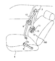
- FIG. 2 is a diagram schematically showing a seat belt device on the driver's seat side.
- the seat belt device 100 includes a seat belt 12 in which a belt anchor 12a at a front end is fixed to a floor of a vehicle body or a seat 6, the seat belt retractor 11 that winds up the seat belt 12, and the seat.
- a guide anchor 7 that guides the seat belt 12 pulled out from the belt retractor 11 toward the occupant's shoulder, a tongue 8 that is slidably supported by the seat belt 12 guided from the guide anchor 7, and a vehicle body
- the buckle 9 is fixed to the floor or the seat 6 and into which the tongue 8 is detachably inserted.
- the configuration of the seat belt device on the passenger seat side is the same as that of the seat belt device 100 on the driver seat side.
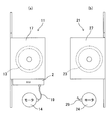
- the spool 13 of the seat belt retractor 11 is rotatably supported by a frame 17 having a U-shaped cross section having a back plate for attaching the seat belt retractor 11 to the vehicle body.
- the ECU 2 and the motor 14 are arranged below the frame 17.
- the motor 14 and the motor drive circuit board 16 provided in the ECU 2 are connected by a harness 19.
- the ECU 2 and the motor 14 may be disposed on the upper portion of the frame 17 or on the back plate.
- the spool 23 of the seat belt retractor 21 is rotatably supported by a frame 27 having a U-shaped cross section, as shown in FIG.
- the motor 24 is disposed below the frame 27.
- the motor 24 and the motor drive circuit board 26 provided in the ECU 2 are connected by a harness 29.
- the motor drive circuit board 16 and the motor drive circuit board 26 are connected in the ECU 2 by a harness (not shown).
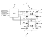
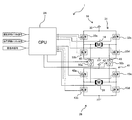
- FIG. 4 is a circuit configuration diagram of the motor drive system of the seat belt retracting system 1.
- the seat belt retracting system 1 includes the motor drive circuit board 16 provided in the seat belt retractor 11 on the driver's seat side and the motor drive circuit board 26 provided on the seat belt retractor 21 on the passenger seat side.
- a CPU 2A provided in the ECU 2 for controlling the electric circuits of the motor drive circuit boards 16 and 26.
- the motor drive circuit board 16 has a driver 31 for driving the motor 14.
- the driver 31 includes a motor power supply 32 and FETs 33a to 33d.
- the gates of the FETs 33a to 33d are connected to the CPU 2A.
- the drains of the FETs 33a and 33c are connected to the motor power source 32, and the sources of the FETs 33a and 33c are connected to the drains of the FETs 33b and 33d.
- the source of the FET 33a is also connected to the + terminal of the motor 14, and the source of the FET 33c is also connected to the-terminal of the motor 14.
- the sources of the FETs 33b and 33d are grounded.
- the + terminal and ⁇ terminal of the motor 14 may be reversed.
- the motor drive circuit board 26 has a driver 41 for driving the motor 24 and three-terminal switches 44a and 44b for switching ON / OFF of the driving operation of the motor 14 by the driver 41.
- the driver 41 includes a motor power supply 42 and FETs 43a to 43d.
- the gates of the FETs 43a to 43d are connected to the CPU 2A.
- the drains of the FETs 43a and 43c are connected to the motor power supply 42, and the sources of the FETs 43a and 43c are connected to the drains of the FETs 43b and 43d.
- the source of the FET 43a is connected to the + terminal of the motor 24 via the switch 44a, and the source of the FET 43c is connected to the-terminal of the motor 24 via the switch 44b.
- the sources of the FETs 43b and 43d are grounded. Further, the switches 44a and 44b are connected to the + terminal and the ⁇ terminal of the motor 14 via the communication harness 45, respectively.
- the switch 44a is switched between a normal position (shown) where the FETs 43a, 43b and the motor 24 are connected and a failure position where the FETs 43a, 43b and the motor 14 are connected.
- the switch 44b is switched between a normal position (illustrated) for connecting the FETs 43c and 43d and the motor 24 and a failure position for connecting the FETs 43c and 43d and the motor 14.
- the CPU 2A controls the drivers 31 and 41 in common. Specifically, the CPU 2A sets the FETs 33a to 33d to operate the motor 14 based on a buckle signal from a buckle sensor (not shown) on the driver's seat side and an emergency signal from a collision prediction sensor (not shown). At the same time, the FETs 43a to 43d are controlled to operate the motor 24 based on the buckle signal from the buckle sensor on the passenger seat side and the emergency signal from the collision prediction sensor.
- the CPU 2A controls the switches 44a and 44b to switch from the normal position to the position at the time of failure when the failure of the driver 31 is detected. Thereby, when the driver 31 on the driver seat side breaks down, the driver seat side driver 41 drives the driver seat side motor 14. The failure of the driver 31 can be detected from the current value or voltage value flowing through the FETs 33a to 33d.
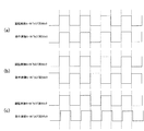
- the polarity is inverted between the motor drive clock on the driver side and the motor drive clock on the passenger side by shifting the state of FIG. 5A by one clock. Clock control is performed so that As a result, no current flows through the drivers 31 and 41 at the same time, so that the required current of the entire ECU 2 can be reduced.
- the rising timing of the motor drive clock on the driver's seat side is shifted from the rising timing of the motor drive clock on the passenger seat side, and the rising timing of the motor drive clock on the driver seat side is shifted.
- the descending timing may be shifted from the falling timing of the motor drive clock on the passenger seat side. Thereby, the maximum current can be reduced.
- the ECU 2 that controls the drivers 31 and 41 in common is provided in the seat belt retractor 11 on the driver's seat side where the use frequency of the seat belt 12 (operating rate of the motor 14) is high.
- the length of the harness that connects the ECU 2 and the driver 31 is shortened, and in some cases, the harness that connects the two becomes unnecessary. Thereby, the noise which arises between ECU2 and the driver 31 can be reduced, without taking the noise countermeasure which causes cost increase in particular. As a result, the drive control of the motor 14 on the driver's seat side can be performed accurately.
- the driver 14 on the passenger seat side controls the motor 14 on the driver seat side, so that the use of the motor 14 can be continued.
- the passenger seat is taken as an example of a seat other than the driver seat, and the driver 41 that drives the motor 24 of the seat belt retractor 21 on the passenger seat side and the motor 14 of the seat belt retractor 11 on the driver seat side are provided.
- the driver 31 to be driven is controlled by a common ECU, but is not limited thereto. That is, instead of the passenger seat, a driver that drives the motor of the seat belt retractor on the side of the rear seat (particularly the rear seat of the driver's seat), and a driver 31 that drives the motor 14 of the seat belt retractor 11 on the driver seat side, You may control by common ECU. In this case, the same effect is obtained.
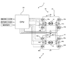
- FIG. 6 is another circuit configuration diagram of the motor drive system of the seat belt retracting system 1. In the figure, the same elements as those shown in FIG.
- the source of the FET 43a and the drain of the FET 43b in the driver 41 are directly connected to the + terminal of the motor 24, and the source of the FET 43c and the drain of the FET 43d are directly connected to the ⁇ terminal of the motor 24.
- the driver 41 has two-terminal type switches 50a and 50b instead of the switches 44a and 44b.
- the + terminal of the motor 24 and the + terminal of the motor 14 are connected via the switch 50 a and the communication harness 45, and the ⁇ terminal of the motor 24 and the ⁇ terminal of the motor 14 are connected via the switch 50 b and the connection harness 45. Connected.
- the switches 50a and 50b are normally in an OFF state (shown).
- the switches 50a and 50b may be provided in the driver 31.
- the CPU 2A controls the switches 50a and 50b to be switched from OFF to ON when a failure of the driver 31 is detected. Thereby, when the driver 31 on the driver's seat side breaks down, the driver's seat side driver 41 controls the driver's seat side motor 14.
- FIG. 7 is still another circuit configuration diagram of the motor drive system of the seat belt retracting system 1. In the figure, the same elements as those shown in FIG.
- the driver 31 has three-terminal type switches 51a and 51b for switching ON / OFF of the driving operation of the motor 14 by the driver 41 in cooperation with the switches 44a and 44b.
- the source of the FET 33a and the drain of the FET 33b in the driver 31 are connected to the positive terminal of the motor 14 through the switch 51a, and the source of the FET 33c and the drain of the FET 33d are connected to the negative terminal of the motor 14 through the switch 51b.
- the switches 51a and 51b are connected to the switches 44a and 44b via the communication harness 45, respectively.
- the switch 51a is switched between a normal position (illustrated) for connecting the FETs 33a and 33b and the motor 14 and a failure position for connecting the switch 44a and the motor 14.
- the switch 51b is switched between a normal position (illustrated) for connecting the FETs 33c and 33d and the motor 14 and a failure position for connecting the switch 44b and the motor 14.
- the switch 44a is switched between a normal position (illustrated) for connecting the FETs 43a and 43b and the motor 24 and a failure position for connecting the FETs 43a and 43b and the switch 51a.
- the switch 44b is switched between a normal position (shown) where the FETs 43c and 43d and the motor 24 are connected and a failure position where the FETs 43c and 43d and the switch 51b are connected.
- the CPU 2A controls the switches 51a and 51b to switch from the normal position to the failure position, and controls the switches 44a and 44b to switch from the normal position to the failure position. .
- the driver's seat side driver 41 controls the driver's seat side motor 14.
- the present invention is not limited to the above embodiment.
- a switch is provided so that the driver's seat side driver 41 controls the driver's seat side motor 14.
- the circuit configuration of the seat belt retracting system 1 can be simplified.
Landscapes
- Engineering & Computer Science (AREA)
- Mechanical Engineering (AREA)
- Automotive Seat Belt Assembly (AREA)
Abstract
【課題】モータ駆動時に生じるノイズを低減する。 【解決手段】シートベルト巻き取りシステム1は、運転席側のシートベルトリトラクタ11と、助手席側のシートベルトリトラクタ21と、運転席側のシートベルトリトラクタ11に設けられた1つのECU2とを備えている。シートベルトリトラクタ11は、運転席側のシートベルト12を巻き取るスプール13と、このスプール13を回転させるモータ14と、このモータ14を駆動するドライバ31を有するモータドライブ回路基板16とを備えている。シートベルトリトラクタ21は、助手席側のシートベルト22を巻き取るスプール23と、このスプール23を回転させるモータ24と、このモータ24を駆動するドライバ41を有するモータドライブ回路基板26とを備えている。
Description
本発明は、車両の運転席側及び助手席側に設けられたシートベルトの巻き取りを行うシートベルト巻き取りシステムに関する。
従来のシートベルト巻き取りシステムとしては、シートベルトを巻き取るスプールと、このスプールを回転させるモータを有するシートベルトリトラクタと、上記モータを駆動するドライバと、このドライバを制御するECUとを備えたものが知られている(例えば、特許文献1参照)。
上記従来技術においては、モータ及びドライバは運転席側及び助手席側のシートベルトリトラクタにそれぞれ設けられており、各ドライバは1つのECUによって制御される。このとき、ECUがドライバから離れた位置に搭載されていると、ECUとドライバとを接続するハーネスが長くなるため、ECUとドライバとの間にノイズが生じやすくなり、ノイズ対策が必要となり、製造コストが上がる。
本発明の目的は、コスト増大を招くノイズ対策を特に行うことなく、モータ駆動時に生じるノイズを低減することができるシートベルト巻き取りシステムを提供することにある。
上記目的を達成するために、本発明のシートベルト巻き取りシステムは、運転席側に設けられた第1シートベルトを巻き取る第1スプールと前記第1スプールを回転させる第1モータとを有する第1シートベルトリトラクタと、前記第1モータを駆動する第1モータ駆動部と、運転席以外の座席側に設けられた第2シートベルトを巻き取る第2スプールと前記第2スプールを回転させる第2モータとを有する第2シートベルトリトラクタと、前記第2モータを駆動する第2モータ駆動部と、第1モータ駆動部及び第2モータ駆動部を共通して制御する1つの共通制御部とを備え、共通制御部は、第1シートベルトリトラクタに設けられていることを特徴とするものである。
本発明のシートベルト巻き取りシステムにおいては、第1シートベルトリトラクタの第1モータ駆動部と第2シートベルトリトラクタの第2モータ駆動部とを共通して制御する1つの共通制御部を、運転席側の第1シートベルトリトラクタに設けることにより、共通制御部と第1モータ駆動部とを接続するハーネスの長さが必要最小限に抑えられる。これにより、運転席側の第1モータを駆動する際に、共通制御部と第1モータ駆動部との間に生じるノイズを低減することができる。
好ましくは、第2モータ駆動部による第1モータの駆動をON/OFFする切換装置を更に備える。
一般に、運転席以外の座席(例えば助手席)は空席になることがあるが、運転席には運転者が乗るため、運転席側のシートベルトの使用頻度はそれ以外の座席側のシートベルトの使用頻度に比べて圧倒的に高い。即ち、この場合には、運転席側の第1モータ駆動部が万が一故障したときでも、第2モータ駆動部による第1モータの駆動をOFFからONに切り換えることにより、第1モータが第2モータ駆動部により駆動されるようになるため、使用頻度の高い第1シートベルトリトラクタの第1モータの使用を優先して継続することができる。
また好ましくは、前記第1モータ駆動部は、前記第1モータを駆動するドライバを備えたモータドライブ回路基板であり、前記第2モータ駆動部は、前記第2モータを駆動するドライバを備えたモータドライブ回路基板である。
また好ましくは、前記第1モータ駆動部及び前記第2モータ駆動部は、
前記共通制御部と共に、前記第1シートベルトリトラクタに設けられている。これにより、共通制御部と第1モータ駆動部とがともに第1シートベルトリトラクタに配置されるので、これらを接続するハーネスの長さを必要最小限に抑えることができる。
前記共通制御部と共に、前記第1シートベルトリトラクタに設けられている。これにより、共通制御部と第1モータ駆動部とがともに第1シートベルトリトラクタに配置されるので、これらを接続するハーネスの長さを必要最小限に抑えることができる。
本発明によれば、コスト増大を招くノイズ対策を特に行わなくても、運転席側の第1モータを駆動する際に、共通制御部と第1モータ駆動部との間に生じるノイズを低減することができる。
以下、本発明の実施形態を図面を参照しつつ説明する。
図1は、本発明のシートベルト巻き取りシステムの一実施形態を示す概略構成図である。図1において、本実施形態のシートベルト巻き取りシステム1は、運転席側のシートベルトリトラクタ11と、助手席側のシートベルトリトラクタ21と、運転席側のシートベルトリトラクタ11に設けられた1つの電子制御ユニット(ECU;共通制御部に相当)2とを備えている。
シートベルトリトラクタ11は、運転席側のシートベルト12を巻き取るスプール13と、このスプール13を回転させるモータ14とを少なくとも備えている。スプール13を回転させるモータ14の駆動力は、動力伝達機構を介してスプール13に伝達される。このモータ14を駆動するドライバ31(図4参照)を有するモータドライブ回路基板16(第1モータ駆動部に相当)は、上記電子制御ユニット2内に設けられている。シートベルトリトラクタ21は、助手席側のシートベルト22を巻き取るスプール23と、このスプール23を回転させるモータ24とを備えている。このモータ24を駆動するドライバ41(図4参照)を有するモータドライブ回路基板26(第2モータ駆動部に相当)も、上記同様、電子制御ユニット2内に設けられている。なお、モータドライブ回路基板16,26を電子制御ユニット2外に設けてもよい。
図2は、運転席側のシートベルト装置を模式的に示す図である。図2において、シートベルト装置100は、先端のベルトアンカー12aが車体の床またはシート6に固定される上記シートベルト12と、このシートベルト12の巻き取りを行う上記シートベルトリトラクタ11と、このシートベルトリトラクタ11から引き出されたシートベルト12を乗員のショルダーの方へガイドするガイドアンカー7と、このガイドアンカー7からガイドされてきたシートベルト12に摺動自在に支持されたタング8と、車体の床またはシート6に固定され、タング8が係脱可能に挿入されるバックル9とから構成されている。なお、助手席側のシートベルト装置の構成は、運転席側のシートベルト装置100と同様である。
シートベルトリトラクタ11のスプール13は、図3(a)に示すように、車体へシートベルトリトラクタ11を取り付ける背板を有する、断面コ字状のフレーム17に回転自在に支持されている。フレーム17の下部には上記のECU2や上記モータ14が配置されている。モータ14と上記ECU2に備えられた上記モータドライブ回路基板16とは、ハーネス19により接続されている。なお、上記ECU2や上記モータ14は、フレーム17の上部又は上記背板に配置されていてもよい。
シートベルトリトラクタ21のスプール23は、図3(b)に示すように、断面コ字状のフレーム27に回転自在に支持されている。フレーム27の下部には上記モータ24が配置されている。モータ24と上記ECU2に備えられた上記モータドライブ回路基板26とは、ハーネス29により接続されている。また、モータドライブ回路基板16とモータドライブ回路基板26とは、ECU2内において、図示しないハーネスにより接続されている。
図4は、シートベルト巻き取りシステム1のモータ駆動系の回路構成図である。図4において、シートベルト巻き取りシステム1は、運転席側のシートベルトリトラクタ11に設けられた上記モータドライブ回路基板16と、助手席側のシートベルトリトラクタ21に設けられた上記モータドライブ回路基板26と、上記ECU2内に備えられ、これらのモータドライブ回路基板16,26の電気回路を制御するCPU2Aとを備えている。
モータドライブ回路基板16は、モータ14を駆動するドライバ31を有している。ドライバ31は、モータ用電源32及びFET33a~33dから構成されている。FET33a~33dのゲートは、CPU2Aと接続されている。FET33a,33cのドレインは、モータ用電源32と接続され、FET33a,33cのソースは、FET33b,33dのドレインと接続されている。また、FET33aのソースは、モータ14の+端子とも接続され、FET33cのソースは、モータ14の-端子とも接続されている。FET33b,33dのソースは、接地されている。なお、モータ14の+端子及び-端子は逆にしてもよい。
モータドライブ回路基板26は、モータ24を駆動するドライバ41と、このドライバ41によるモータ14の駆動動作のON/OFFを切り換える3端子型のスイッチ44a,44bとを有している。
ドライバ41は、モータ用電源42及びFET43a~43dから構成されている。FET43a~43dのゲートは、CPU2Aと接続されている。FET43a,43cのドレインは、モータ用電源42と接続され、FET43a,43cのソースは、FET43b,43dのドレインと接続されている。また、FET43aのソースは、スイッチ44aを介してモータ24の+端子と接続され、FET43cのソースは、スイッチ44bを介してモータ24の-端子と接続されている。FET43b,43dのソースは、接地されている。さらに、スイッチ44a,44bは、連絡用ハーネス45を介してモータ14の+端子及び-端子とそれぞれ接続されている。
スイッチ44aは、FET43a,43bとモータ24とを接続する通常位置(図示)と、FET43a,43bとモータ14とを接続する故障時位置との間で切り換えられる。スイッチ44bは、FET43c,43dとモータ24とを接続する通常位置(図示)と、FET43c,43dとモータ14とを接続する故障時位置との間で切り換えられる。
CPU2Aは、ドライバ31,41を共通して制御する。具体的には、CPU2Aは、運転席側のバックルセンサ(不図示)からのバックル信号及び衝突予知センサ(不図示)からの緊急時信号に基づいて、モータ14を作動させるようにFET33a~33dを制御すると共に、助手席側のバックルセンサからのバックル信号及び衝突予知センサからの緊急時信号に基づいて、モータ24を作動させるようにFET43a~43dを制御する。
また、CPU2Aは、ドライバ31の故障が検知されたときに、スイッチ44a,44bを通常位置から故障時位置に切り換えるように制御する。これにより、運転席側のドライバ31が故障した場合には、助手席側のドライバ41によって運転席側のモータ14が駆動されることとなる。なお、ドライバ31の故障は、FET33a~33dを流れる電流値や電圧値等から検知することができる。
ここで、CPU2Aによりドライバ31,41を制御する際に、図5(a)に示すように、運転席側のモータドライブ用クロックと助手席側のモータドライブ用クロックとで極性を同じにすると、各クロックの立上りタイミング及び立下りタイミングで瞬間的にドライバ31,41に電流が同時に流れるため、CPU2Aの必要電流が増大してしまう。
そこで、図5(b)に示すように、上記図5(a)の状態から1クロック分ずらすことにより、運転席側のモータドライブ用クロックと助手席側のモータドライブ用クロックとで極性を反転させるように、クロック制御を行う。これにより、ドライバ31,41に同時に電流が流れることが無いため、ECU2全体の必要電流を低減することができる。さらには、図5(c)に示すように、運転席側のモータドライブ用クロックの立上りタイミングと助手席側のモータドライブ用クロックの立上りタイミングとをずらし、運転席側のモータドライブ用クロックの立下りタイミングと助手席側のモータドライブ用クロックの立下りタイミングとをずらすようにしてもよい。これにより、最大電流を低減することができる。
以上のように本実施形態においては、シートベルト12の使用頻度(モータ14の稼働率)の高い運転席側のシートベルトリトラクタ11に、ドライバ31,41を共通して制御するECU2を設けたので、ECU2とドライバ31とを接続するハーネスの長さが短くなり、場合によっては両者を接続するハーネスが不要となる。これにより、コスト増大を招くノイズ対策を特に行うことなく、ECU2とドライバ31との間で生じるノイズを低減することができる。この結果、運転席側のモータ14の駆動制御を正確に行うことができる。
また、運転席側のドライバ31が故障した場合には、助手席側のドライバ41によって運転席側のモータ14を制御するので、モータ14の使用を継続することができる。
なお、上記では、運転席以外の座席の一例として助手席を例に取り、助手席側のシートベルトリトラクタ21のモータ24を駆動するドライバ41と、運転席側のシートベルトリトラクタ11のモータ14を駆動するドライバ31とを、共通のECUで制御したが、これに限られない。すなわち、助手席の代わりに、後部座席(特に運転席の後席)側のシートベルトリトラクタのモータを駆動するドライバと、運転席側のシートベルトリトラクタ11のモータ14を駆動するドライバ31とを、共通のECUで制御してもよい。この場合も同様の効果を得る。
図6は、シートベルト巻き取りシステム1のモータ駆動系の他の回路構成図である。図中、図4に示すものと同一の要素には同じ符号を付してある。
図6において、ドライバ41におけるFET43aのソース及びFET43bのドレインは、モータ24の+端子と直接接続され、同FET43cのソース及びFET43dのドレインは、モータ24の-端子と直接接続されている。
また、ドライバ41は、上記のスイッチ44a,44bの代わりに、2端子型のスイッチ50a,50bを有している。モータ24の+端子とモータ14の+端子とは、スイッチ50a及び連絡用ハーネス45を介して接続され、モータ24の-端子とモータ14の-端子とは、スイッチ50b及び連絡用ハーネス45を介して接続されている。スイッチ50a,50bは、通常はOFF状態(図示)となっている。なお、スイッチ50a,50bは、ドライバ31に設けられていても良い。
CPU2Aは、ドライバ31の故障が検知されたときに、スイッチ50a,50bをOFFからONに切り換えるように制御する。これにより、運転席側のドライバ31が故障した場合には、助手席側のドライバ41によって運転席側のモータ14が制御されることとなる。
図7は、シートベルト巻き取りシステム1のモータ駆動系の更に他の回路構成図である。図中、図4に示すものと同一の要素には同じ符号を付してある。
図7において、ドライバ31は、上記のスイッチ44a,44bと協働して、ドライバ41によるモータ14の駆動動作のON/OFFを切り換える3端子型のスイッチ51a,51bを有している。ドライバ31におけるFET33aのソース及びFET33bのドレインは、スイッチ51aを介してモータ14の+端子と接続され、同FET33cのソース及びFET33dのドレインは、スイッチ51bを介してモータ14の-端子と接続されている。スイッチ51a,51bは、連絡用ハーネス45を介してスイッチ44a,44bとそれぞれ接続されている。スイッチ51aは、FET33a,33bとモータ14とを接続する通常位置(図示)と、スイッチ44aとモータ14とを接続する故障時位置との間で切り換えられる。スイッチ51bは、FET33c,33dとモータ14とを接続する通常位置(図示)と、スイッチ44bとモータ14とを接続する故障時位置との間で切り換えられる。
スイッチ44aは、FET43a,43bとモータ24とを接続する通常位置(図示)と、FET43a,43bとスイッチ51aとを接続する故障時位置との間で切り換えられる。スイッチ44bは、FET43c,43dとモータ24とを接続する通常位置(図示)と、FET43c,43dとスイッチ51bとを接続する故障時位置との間で切り換えられる。
CPU2Aは、ドライバ31の故障が検知されたときに、スイッチ51a,51bを通常位置から故障時位置に切り換えるように制御すると共に、スイッチ44a,44bを通常位置から故障時位置に切り換えるように制御する。これにより、運転席側のドライバ31が故障した場合には、助手席側のドライバ41によって運転席側のモータ14が制御されることとなる。
なお、本発明は、上記実施形態に限定されるものではない。例えば上記実施形態では、運転席側のドライバ31が故障したときに、助手席側のドライバ41によって運転席側のモータ14を制御するように切り換えるスイッチを設けたが、そのようなスイッチは特に無くてもよい。この場合には、シートベルト巻き取りシステム1の回路構成を簡単化することができる。
1 シートベルト巻き取りシステム
2 ECU(共通制御部)
11 シートベルトリトラクタ(第1シートベルトリトラクタ)
12 シートベルト(第1シートベルト)
13 スプール(第1スプール)
14 モータ(第1モータ)
21 シートベルトリトラクタ(第2シートベルトリトラクタ)
22 シートベルト(第2シートベルト)
23 スプール(第2スプール)
24 モータ(第2モータ)
31 ドライバ
32 ドライバ
44a スイッチ(切換装置)
44b スイッチ(切換装置)
45 連絡用ハーネス(切換装置)
50a スイッチ(切換装置)
50b スイッチ(切換装置)
51a スイッチ(切換装置)
51b スイッチ(切換装置)
2 ECU(共通制御部)
11 シートベルトリトラクタ(第1シートベルトリトラクタ)
12 シートベルト(第1シートベルト)
13 スプール(第1スプール)
14 モータ(第1モータ)
21 シートベルトリトラクタ(第2シートベルトリトラクタ)
22 シートベルト(第2シートベルト)
23 スプール(第2スプール)
24 モータ(第2モータ)
31 ドライバ
32 ドライバ
44a スイッチ(切換装置)
44b スイッチ(切換装置)
45 連絡用ハーネス(切換装置)
50a スイッチ(切換装置)
50b スイッチ(切換装置)
51a スイッチ(切換装置)
51b スイッチ(切換装置)
Claims (4)
- 運転席側に設けられた第1シートベルト(12)を巻き取る第1スプール(13)と前記第1スプール(13)を回転させる第1モータ(14)とを有する第1シートベルトリトラクタ(11)と、
前記第1モータ(14)を駆動する第1モータ駆動部(16)と、
運転席以外の座席側に設けられた第2シートベルト(22)を巻き取る第2スプール(23)と、前記第2スプール(23)を回転させる第2モータ(24)とを有する第2シートベルトリトラクタ(21)と、
前記第2モータ(24)を駆動する第2モータ駆動部(26)と、
前記第1モータ駆動部(16)及び前記第2モータ駆動部(26)を共通して制御する1つの共通制御部(2)とを備え、
前記共通制御部(2)は、前記第1シートベルトリトラクタ(11)に設けられていることを特徴とするシートベルト巻き取りシステム(1)。 - 請求項1記載のシートベルト巻き取りシステムにおいて、
前記第2モータ駆動部(26)による前記第1モータ(14)の駆動をON/OFFする切換装置(44a,44b,45;50a,50b,45;44a,44b,50a,50b,45)を更に備えることを特徴とするシートベルト巻き取りシステム(1)。 - 請求項1又は請求項2記載のシートベルト巻き取りシステムにおいて、
前記第1モータ駆動部は、
前記第1モータ(14)を駆動するドライバ(31)を備えたモータドライブ回路基板(16)であり、
前記第2モータ駆動部は、
前記第2モータ(24)を駆動するドライバ(41)を備えたモータドライブ回路基板(26)である
ことを特徴とするシートベルト巻き取りシステム(1)。 - 請求項1記載のシートベルト巻き取りシステムにおいて、
前記第1モータ駆動部(16)及び前記第2モータ駆動部(26)は、
前記共通制御部(2)と共に、前記第1シートベルトリトラクタ(11)に設けられていることを特徴とするシートベルト巻き取りシステム(1)。
Applications Claiming Priority (2)
| Application Number | Priority Date | Filing Date | Title |
|---|---|---|---|
| JP2011-027864 | 2011-02-10 | ||
| JP2011027864A JP5633968B2 (ja) | 2011-02-10 | 2011-02-10 | シートベルト巻き取りシステム |
Publications (1)
| Publication Number | Publication Date |
|---|---|
| WO2012108352A1 true WO2012108352A1 (ja) | 2012-08-16 |
Family
ID=46638568
Family Applications (1)
| Application Number | Title | Priority Date | Filing Date |
|---|---|---|---|
| PCT/JP2012/052503 Ceased WO2012108352A1 (ja) | 2011-02-10 | 2012-02-03 | シートベルト巻き取りシステム |
Country Status (2)
| Country | Link |
|---|---|
| JP (1) | JP5633968B2 (ja) |
| WO (1) | WO2012108352A1 (ja) |
Citations (1)
| Publication number | Priority date | Publication date | Assignee | Title |
|---|---|---|---|---|
| JP2009234327A (ja) * | 2008-03-26 | 2009-10-15 | Denso Corp | シートベルト巻取ユニット |
Family Cites Families (2)
| Publication number | Priority date | Publication date | Assignee | Title |
|---|---|---|---|---|
| JP4269991B2 (ja) * | 2004-03-22 | 2009-05-27 | 株式会社デンソー | 盗難防止装置 |
| JP4375372B2 (ja) * | 2006-08-31 | 2009-12-02 | 株式会社日立製作所 | シートベルトリトラクタ装置 |
-
2011
- 2011-02-10 JP JP2011027864A patent/JP5633968B2/ja active Active
-
2012
- 2012-02-03 WO PCT/JP2012/052503 patent/WO2012108352A1/ja not_active Ceased
Patent Citations (1)
| Publication number | Priority date | Publication date | Assignee | Title |
|---|---|---|---|---|
| JP2009234327A (ja) * | 2008-03-26 | 2009-10-15 | Denso Corp | シートベルト巻取ユニット |
Also Published As
| Publication number | Publication date |
|---|---|
| JP2012166627A (ja) | 2012-09-06 |
| JP5633968B2 (ja) | 2014-12-03 |
Similar Documents
| Publication | Publication Date | Title |
|---|---|---|
| EP2716492B1 (en) | Vehicle seat device | |
| JP2009278729A (ja) | モータ駆動装置、及び駆動装置状態判定方法 | |
| JP6607975B2 (ja) | 車両用制御装置 | |
| JP2006160041A (ja) | シートベルト装置 | |
| JP6848512B2 (ja) | 開閉体駆動モータ及び開閉体駆動システム | |
| US10125530B2 (en) | Power window device | |
| JP5633968B2 (ja) | シートベルト巻き取りシステム | |
| WO2012063456A1 (en) | Combination switch | |
| WO2016051742A1 (ja) | モータ制御装置、このモータ制御装置を備えるモータユニット、モータユニットを備える自動車、および、モータ制御方法 | |
| US7272303B2 (en) | Method and control circuit for driving an electric motor of a seatbelt retractor | |
| JP2015051718A (ja) | モータ制御装置 | |
| JP2008056075A (ja) | シートベルトリトラクタ装置 | |
| JP2009159697A (ja) | モータ制御装置 | |
| KR101040005B1 (ko) | 하이브리드 차량의 에어백 장치를 이용한 고전압 릴레이제어 시스템 | |
| CN102951114A (zh) | 限制装置 | |
| JP6514344B2 (ja) | モータ駆動制御装置およびシートベルト用モータ駆動制御装置 | |
| JP2012144069A (ja) | シートベルトリトラクタの制御装置 | |
| JP2006290089A (ja) | 車載通信装置および方法 | |
| JP2008006998A (ja) | シートベルト制御装置,シートベルト巻き取り装置及び車両用安全装置 | |
| JP2007276715A (ja) | 車両用乗員保護装置 | |
| JP5422292B2 (ja) | 車両用シートベルトリトラクター制御装置 | |
| JP2012096686A (ja) | シートベルト装置 | |
| JP2010105460A (ja) | シートベルトリトラクター用モータの制御装置 | |
| JP4760182B2 (ja) | シートベルト制御装置 | |
| JP2005271729A (ja) | プリクラッシュシートベルト装置 |
Legal Events
| Date | Code | Title | Description |
|---|---|---|---|
| 121 | Ep: the epo has been informed by wipo that ep was designated in this application |
Ref document number: 12745203 Country of ref document: EP Kind code of ref document: A1 |
|
| NENP | Non-entry into the national phase |
Ref country code: DE |
|
| 122 | Ep: pct application non-entry in european phase |
Ref document number: 12745203 Country of ref document: EP Kind code of ref document: A1 |