WO2012108296A1 - ターボ式過給機付き内燃機関の制御装置 - Google Patents
ターボ式過給機付き内燃機関の制御装置 Download PDFInfo
- Publication number
- WO2012108296A1 WO2012108296A1 PCT/JP2012/052077 JP2012052077W WO2012108296A1 WO 2012108296 A1 WO2012108296 A1 WO 2012108296A1 JP 2012052077 W JP2012052077 W JP 2012052077W WO 2012108296 A1 WO2012108296 A1 WO 2012108296A1
- Authority
- WO
- WIPO (PCT)
- Prior art keywords
- internal combustion
- combustion engine
- scavenging
- amount
- control device
- Prior art date
Links
Images


Classifications
-
- F—MECHANICAL ENGINEERING; LIGHTING; HEATING; WEAPONS; BLASTING
- F02—COMBUSTION ENGINES; HOT-GAS OR COMBUSTION-PRODUCT ENGINE PLANTS
- F02D—CONTROLLING COMBUSTION ENGINES
- F02D13/00—Controlling the engine output power by varying inlet or exhaust valve operating characteristics, e.g. timing
- F02D13/02—Controlling the engine output power by varying inlet or exhaust valve operating characteristics, e.g. timing during engine operation
-
- F—MECHANICAL ENGINEERING; LIGHTING; HEATING; WEAPONS; BLASTING
- F02—COMBUSTION ENGINES; HOT-GAS OR COMBUSTION-PRODUCT ENGINE PLANTS
- F02D—CONTROLLING COMBUSTION ENGINES
- F02D41/00—Electrical control of supply of combustible mixture or its constituents
- F02D41/02—Circuit arrangements for generating control signals
- F02D41/021—Introducing corrections for particular conditions exterior to the engine
- F02D41/0235—Introducing corrections for particular conditions exterior to the engine in relation with the state of the exhaust gas treating apparatus
-
- F—MECHANICAL ENGINEERING; LIGHTING; HEATING; WEAPONS; BLASTING
- F02—COMBUSTION ENGINES; HOT-GAS OR COMBUSTION-PRODUCT ENGINE PLANTS
- F02B—INTERNAL-COMBUSTION PISTON ENGINES; COMBUSTION ENGINES IN GENERAL
- F02B25/00—Engines characterised by using fresh charge for scavenging cylinders
- F02B25/14—Engines characterised by using fresh charge for scavenging cylinders using reverse-flow scavenging, e.g. with both outlet and inlet ports arranged near bottom of piston stroke
- F02B25/145—Engines characterised by using fresh charge for scavenging cylinders using reverse-flow scavenging, e.g. with both outlet and inlet ports arranged near bottom of piston stroke with intake and exhaust valves exclusively in the cylinder head
-
- F—MECHANICAL ENGINEERING; LIGHTING; HEATING; WEAPONS; BLASTING
- F02—COMBUSTION ENGINES; HOT-GAS OR COMBUSTION-PRODUCT ENGINE PLANTS
- F02D—CONTROLLING COMBUSTION ENGINES
- F02D13/00—Controlling the engine output power by varying inlet or exhaust valve operating characteristics, e.g. timing
- F02D13/02—Controlling the engine output power by varying inlet or exhaust valve operating characteristics, e.g. timing during engine operation
- F02D13/0261—Controlling the valve overlap
-
- F—MECHANICAL ENGINEERING; LIGHTING; HEATING; WEAPONS; BLASTING
- F02—COMBUSTION ENGINES; HOT-GAS OR COMBUSTION-PRODUCT ENGINE PLANTS
- F02D—CONTROLLING COMBUSTION ENGINES
- F02D23/00—Controlling engines characterised by their being supercharged
-
- F—MECHANICAL ENGINEERING; LIGHTING; HEATING; WEAPONS; BLASTING
- F02—COMBUSTION ENGINES; HOT-GAS OR COMBUSTION-PRODUCT ENGINE PLANTS
- F02D—CONTROLLING COMBUSTION ENGINES
- F02D23/00—Controlling engines characterised by their being supercharged
- F02D23/02—Controlling engines characterised by their being supercharged the engines being of fuel-injection type
-
- F—MECHANICAL ENGINEERING; LIGHTING; HEATING; WEAPONS; BLASTING
- F02—COMBUSTION ENGINES; HOT-GAS OR COMBUSTION-PRODUCT ENGINE PLANTS
- F02D—CONTROLLING COMBUSTION ENGINES
- F02D41/00—Electrical control of supply of combustible mixture or its constituents
- F02D41/0002—Controlling intake air
- F02D41/0007—Controlling intake air for control of turbo-charged or super-charged engines
-
- F—MECHANICAL ENGINEERING; LIGHTING; HEATING; WEAPONS; BLASTING
- F02—COMBUSTION ENGINES; HOT-GAS OR COMBUSTION-PRODUCT ENGINE PLANTS
- F02D—CONTROLLING COMBUSTION ENGINES
- F02D41/00—Electrical control of supply of combustible mixture or its constituents
- F02D41/02—Circuit arrangements for generating control signals
- F02D41/04—Introducing corrections for particular operating conditions
-
- F—MECHANICAL ENGINEERING; LIGHTING; HEATING; WEAPONS; BLASTING
- F02—COMBUSTION ENGINES; HOT-GAS OR COMBUSTION-PRODUCT ENGINE PLANTS
- F02D—CONTROLLING COMBUSTION ENGINES
- F02D41/00—Electrical control of supply of combustible mixture or its constituents
- F02D41/02—Circuit arrangements for generating control signals
- F02D41/14—Introducing closed-loop corrections
- F02D41/1438—Introducing closed-loop corrections using means for determining characteristics of the combustion gases; Sensors therefor
- F02D41/1444—Introducing closed-loop corrections using means for determining characteristics of the combustion gases; Sensors therefor characterised by the characteristics of the combustion gases
- F02D41/1448—Introducing closed-loop corrections using means for determining characteristics of the combustion gases; Sensors therefor characterised by the characteristics of the combustion gases the characteristics being an exhaust gas pressure
- F02D41/145—Introducing closed-loop corrections using means for determining characteristics of the combustion gases; Sensors therefor characterised by the characteristics of the combustion gases the characteristics being an exhaust gas pressure with determination means using an estimation
-
- F—MECHANICAL ENGINEERING; LIGHTING; HEATING; WEAPONS; BLASTING
- F02—COMBUSTION ENGINES; HOT-GAS OR COMBUSTION-PRODUCT ENGINE PLANTS
- F02D—CONTROLLING COMBUSTION ENGINES
- F02D41/00—Electrical control of supply of combustible mixture or its constituents
- F02D41/02—Circuit arrangements for generating control signals
- F02D41/14—Introducing closed-loop corrections
- F02D41/1438—Introducing closed-loop corrections using means for determining characteristics of the combustion gases; Sensors therefor
- F02D41/1444—Introducing closed-loop corrections using means for determining characteristics of the combustion gases; Sensors therefor characterised by the characteristics of the combustion gases
- F02D41/146—Introducing closed-loop corrections using means for determining characteristics of the combustion gases; Sensors therefor characterised by the characteristics of the combustion gases the characteristics being an NOx content or concentration
- F02D41/1461—Introducing closed-loop corrections using means for determining characteristics of the combustion gases; Sensors therefor characterised by the characteristics of the combustion gases the characteristics being an NOx content or concentration of the exhaust gases emitted by the engine
- F02D41/1462—Introducing closed-loop corrections using means for determining characteristics of the combustion gases; Sensors therefor characterised by the characteristics of the combustion gases the characteristics being an NOx content or concentration of the exhaust gases emitted by the engine with determination means using an estimation
-
- F—MECHANICAL ENGINEERING; LIGHTING; HEATING; WEAPONS; BLASTING
- F02—COMBUSTION ENGINES; HOT-GAS OR COMBUSTION-PRODUCT ENGINE PLANTS
- F02D—CONTROLLING COMBUSTION ENGINES
- F02D41/00—Electrical control of supply of combustible mixture or its constituents
- F02D41/0002—Controlling intake air
- F02D2041/001—Controlling intake air for engines with variable valve actuation
-
- F—MECHANICAL ENGINEERING; LIGHTING; HEATING; WEAPONS; BLASTING
- F02—COMBUSTION ENGINES; HOT-GAS OR COMBUSTION-PRODUCT ENGINE PLANTS
- F02D—CONTROLLING COMBUSTION ENGINES
- F02D41/00—Electrical control of supply of combustible mixture or its constituents
- F02D41/02—Circuit arrangements for generating control signals
- F02D41/14—Introducing closed-loop corrections
- F02D41/1401—Introducing closed-loop corrections characterised by the control or regulation method
- F02D2041/1433—Introducing closed-loop corrections characterised by the control or regulation method using a model or simulation of the system
-
- F—MECHANICAL ENGINEERING; LIGHTING; HEATING; WEAPONS; BLASTING
- F02—COMBUSTION ENGINES; HOT-GAS OR COMBUSTION-PRODUCT ENGINE PLANTS
- F02D—CONTROLLING COMBUSTION ENGINES
- F02D2200/00—Input parameters for engine control
- F02D2200/70—Input parameters for engine control said parameters being related to the vehicle exterior
- F02D2200/703—Atmospheric pressure
-
- F—MECHANICAL ENGINEERING; LIGHTING; HEATING; WEAPONS; BLASTING
- F02—COMBUSTION ENGINES; HOT-GAS OR COMBUSTION-PRODUCT ENGINE PLANTS
- F02D—CONTROLLING COMBUSTION ENGINES
- F02D41/00—Electrical control of supply of combustible mixture or its constituents
- F02D41/02—Circuit arrangements for generating control signals
- F02D41/14—Introducing closed-loop corrections
- F02D41/1438—Introducing closed-loop corrections using means for determining characteristics of the combustion gases; Sensors therefor
- F02D41/1444—Introducing closed-loop corrections using means for determining characteristics of the combustion gases; Sensors therefor characterised by the characteristics of the combustion gases
- F02D41/1454—Introducing closed-loop corrections using means for determining characteristics of the combustion gases; Sensors therefor characterised by the characteristics of the combustion gases the characteristics being an oxygen content or concentration or the air-fuel ratio
- F02D41/1458—Introducing closed-loop corrections using means for determining characteristics of the combustion gases; Sensors therefor characterised by the characteristics of the combustion gases the characteristics being an oxygen content or concentration or the air-fuel ratio with determination means using an estimation
-
- Y—GENERAL TAGGING OF NEW TECHNOLOGICAL DEVELOPMENTS; GENERAL TAGGING OF CROSS-SECTIONAL TECHNOLOGIES SPANNING OVER SEVERAL SECTIONS OF THE IPC; TECHNICAL SUBJECTS COVERED BY FORMER USPC CROSS-REFERENCE ART COLLECTIONS [XRACs] AND DIGESTS
- Y02—TECHNOLOGIES OR APPLICATIONS FOR MITIGATION OR ADAPTATION AGAINST CLIMATE CHANGE
- Y02T—CLIMATE CHANGE MITIGATION TECHNOLOGIES RELATED TO TRANSPORTATION
- Y02T10/00—Road transport of goods or passengers
- Y02T10/10—Internal combustion engine [ICE] based vehicles
- Y02T10/12—Improving ICE efficiencies
Definitions
- the present invention relates to control of an internal combustion engine including a variable valve mechanism and a turbocharger.
- a variable valve mechanism is controlled to provide a valve overlap period. During this valve overlap period, the residual gas in the cylinder is scavenged into the exhaust passage using the differential pressure between the intake pressure and the exhaust pressure. A technique for increasing the amount of fresh air is known.
- JP 2006-283636A discloses a technique for obtaining a scavenging effect by controlling the throttle valve opening so that the intake pressure becomes higher than the exhaust pressure during the valve overlap period.
- the scavenging amount during the valve overlap period varies depending on the operating state of the internal combustion engine and the operating environment even if the valve overlap period is the same.
- the exhaust pressure is different between the steady state where the rotation speed of the turbocharger is constant and the transient state where the rotation speed increases, so the engine rotation speed, load, etc.
- the scavenging amount is different even in the same operating state and the same overlap period length.
- valve overlap period is controlled by searching a map in which the valve overlap period is assigned to the engine speed and load as in JP 2006-283636A, a scavenging amount suitable for the operating state and operating environment is not necessarily obtained. Not always.
- an object of the present invention is to obtain a scavenging amount suitable for an operating state and an operating environment even in an internal combustion engine with a turbocharger.
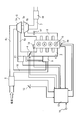
- FIG. 1 is a configuration diagram of a system to which this embodiment is applied.
- FIG. 2 is a diagram showing a stroke order of the in-line four-cylinder internal combustion engine.
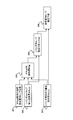
- FIG. 3 is a block diagram showing the calculation contents for setting the fuel injection amount, which is executed by the control unit.
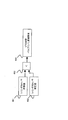
- FIG. 4 is a block diagram of control executed by the control unit to determine whether or not to reduce the valve overlap period.
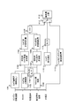
- FIG. 5 is a block diagram showing the calculation contents for obtaining the scavenging rate, which is executed by the control unit.
- FIG. 6 is a block diagram showing the calculation contents for obtaining the exhaust pressure executed by the control unit.
- FIG. 7 is a block diagram showing the calculation contents for obtaining the transient exhaust pressure fluctuation executed by the control unit.
- FIG. 1 is a configuration diagram of a system to which this embodiment is applied.
- FIG. 2 is a diagram showing a stroke order of the in-line four-cylinder internal combustion engine.
- FIG. 3 is a block diagram showing the calculation contents for
- FIG. 8 is a block diagram showing the calculation contents for determining the conversion angle of the variable valve mechanism executed by the control unit.
- FIG. 9 is a block diagram for calculating the scavenging amount upper limit value based on the catalyst temperature, which is executed by the control unit.
- FIG. 10 is a block diagram for calculating the scavenging amount upper limit value based on the NOx emission amount, which is executed by the control unit.
- FIG. 11 is a block diagram for calculating the scavenging amount upper limit value when the torque suddenly changes, executed by the control unit.
- FIG. 1 is a system configuration diagram of an internal combustion engine to which the present embodiment is applied.
- a throttle chamber 4 for adjusting the amount of air flowing into the internal combustion engine 1 is provided at the inlet of the intake manifold 2 of the internal combustion engine 1, and an intake passage 6 is connected upstream thereof.
- a compressor 5 a of the supercharger 5 is installed on the upstream side of the throttle chamber 4 in the intake passage 6, and an air flow meter 8 for detecting the intake air amount is installed further on the upstream side.
- a fuel injection valve 15 that directly injects fuel into the cylinder is disposed in each cylinder of the internal combustion engine 1.
- a turbine 5 b of the supercharger 5 is installed in the exhaust passage 7.
- the supercharger 5 is a so-called turbocharger, and a compressor 5a and a turbine 5b are connected via a shaft 5c. For this reason, when the turbine 5b is rotated by the exhaust energy of the internal combustion engine 1, the compressor 5a rotates and pressure-feeds the intake air to the downstream side.
- An exhaust gas purification catalyst 18 is disposed downstream of the turbine 5b.
- a three-way catalyst is used as the exhaust catalyst 18.
- the recirculation passage 10 is a passage connecting the intake passage 6a and an intake passage downstream of the air flow meter 8 and upstream of the compressor 5a (hereinafter referred to as an intake passage 6b), and is provided in the middle.
- an intake passage 6b an intake passage downstream of the air flow meter 8 and upstream of the compressor 5a
- the recirculation valve 9 is opened when the differential pressure between the supercharging pressure and the pressure in the intake manifold 2 (hereinafter referred to as the intake pipe pressure) exceeds a predetermined value, as is generally known.
- the intake pipe pressure For example, the reaction force of the built-in spring is urged in the valve closing direction against the valve body provided inside, and the boost pressure acts in the valve opening direction of the valve body, while the intake pressure is applied in the valve closing direction.
- the valve is opened.
- the differential pressure between the supercharging pressure and the intake pipe pressure when the recirculation valve 9 is opened can be set to an arbitrary value depending on the spring constant of the spring.
- variable valve mechanism 14 changes the intake valve closing timing (IVC) so that an overlap period in which both the exhaust valve and the intake valve are opened occurs.
- IVC intake valve closing timing
- a generally known variable valve mechanism such as one that changes the rotational phase of the intake camshaft relative to the crankshaft or one that changes the operating angle of the intake valve can be used.
- a similar variable valve mechanism 14 may be provided on the exhaust valve side to variably control the valve timing of the intake valve and the exhaust valve.
- the control unit 12 reads parameters relating to the operating state such as the intake air amount detected by the air flow meter 8, the accelerator opening detected by the accelerator opening sensor 13, the engine speed detected by the crank angle sensor 20, and the like. Controls ignition timing, valve timing, air-fuel ratio, etc.
- valve timing control and air-fuel ratio control performed by the control unit 12 will be described.
- control unit 12 When the pressure in the intake manifold 2 is higher than the pressure in the exhaust manifold 3, the control unit 12 is a variable valve operation so that a valve overlap period during which the intake valve and the exhaust valve are open occurs. Actuate mechanism 14.
- FIG. 2 shows the stroke order of an in-line four-cylinder internal combustion engine in which the ignition order is the first cylinder, the third cylinder, the fourth cylinder, and the second cylinder.
- the hatched portion in the figure indicates the valve overlap period.
- the exhaust manifold 3 joins the exhaust gas discharged from the cylinder during the exhaust stroke and the scavenging gas from the other cylinders during the intake stroke at that time.
- the exhaust gas exhausted in the exhaust stroke # 3ex of the third cylinder in FIG. 2 and the scavenged gas scavenged in the valve overlap period # 1sc of the first cylinder that becomes the intake stroke at that time merge.
- the amount of gas introduced into the turbine 5b increases when there is no valve overlap period, that is, when there is no scavenging.
- the rotational speed of the turbine 5b increases and the supercharging pressure by the compressor 5a increases.
- the scavenging discharges the residual gas in the cylinder together with the fresh air gas, the efficiency of filling the fresh air in the cylinder is increased as a result.
- the energy for rotating the turbine 5b is obtained by burning the mixture of the exhaust gas and the scavenging gas joined by the exhaust manifold 3 before flowing into the turbine 5b by air-fuel ratio control described later. Increase.
- the fuel injection amount is set so that the air-fuel ratio is easy to burn. That is, the air-fuel ratio in the cylinder is made richer than the stoichiometric air-fuel ratio, exhaust gas containing unburned hydrocarbons is exhausted, and this exhaust gas and scavenging gas are mixed to facilitate combustion. For example, the fuel injection amount is set so that the stoichiometric air-fuel ratio is obtained.
- the exhaust gas discharged in the exhaust stroke # 3ex of the third cylinder and the valve overlap of the first cylinder A fuel injection amount is set such that the mixture of scavenging gas discharged in the period # 1sc has an air-fuel ratio at which it is easy to burn. That is, when focusing on the air-fuel ratio in the cylinder of the third cylinder, the air-fuel ratio becomes richer than the stoichiometric air-fuel ratio, and exhaust gas including unburned fuel is discharged in the exhaust stroke.
- the fuel injection amount set as described above is all injected by one fuel injection per stroke.
- the fuel injection timing is after the valve overlap period during the intake stroke, that is, after the exhaust valve is closed, or during the compression stroke. Details of the air-fuel ratio control will be described later.
- the fuel that becomes the unburned hydrocarbon in the exhaust gas changes from a higher hydrocarbon with a long carbon chain to a lower hydrocarbon with a short carbon chain by receiving the heat of combustion during the expansion stroke, It becomes more combustible.
- the air-fuel ratio in the cylinder becomes richer than the stoichiometric air-fuel ratio, it approaches the output air-fuel ratio, so that the output can be improved as compared with the case of operating at the stoichiometric air-fuel ratio.
- the inside of the cylinder is cooled by the latent heat of vaporization when the fuel is vaporized in the cylinder, it contributes to the improvement of the charging efficiency.
- FIG. 3 is a block diagram showing the calculation contents for setting the fuel injection amount to be injected into the cylinder. This block diagram includes estimation of the air-fuel ratio in the cylinder and in the exhaust manifold 3, which is performed using the set fuel injection amount.
- the exhaust pipe air-fuel ratio target value setting unit 301 sets an exhaust pipe target air-fuel ratio that is a target air-fuel ratio in the exhaust manifold 3.
- the target air-fuel ratio is set to an air-fuel ratio at which the mixture of exhaust gas and scavenging gas is easy to burn, for example, the stoichiometric air-fuel ratio.
- the air-fuel ratio is not limited to the stoichiometric air-fuel ratio.
- the air-fuel ratio is set so that the mixture of the exhaust gas and the scavenging gas satisfies the required value of the exhaust performance, that is, does not decrease the conversion efficiency of the exhaust catalyst 18. May be. Even in this case, the charging efficiency in the cylinder is improved by the scavenging effect, the generated torque is increased, and the exhaust performance can be prevented from being lowered.
- the in-cylinder trap intake air amount estimation unit 302 is a cylinder that is confined in the cylinder at the end of the intake stroke of the intake air amount based on the intake air amount detected by the air flow meter 8 and the scavenging rate. Estimate the amount of intake air in the inner trap.
- the scavenging rate is a value obtained by dividing the amount of fresh air by the amount of gas in the cylinder. A method for calculating the scavenging rate will be described later.
- the cylinder scavenging gas amount estimation unit 303 is the amount of the intake air amount that flows out to the exhaust manifold 3 during the valve overlap period for the cylinder that is in the intake stroke when the cylinder whose trap trap intake air amount has been calculated is in the exhaust stroke.
- the cylinder scavenging gas amount is estimated based on the scavenging rate and the intake air amount.
- the in-cylinder fuel injection amount setting unit 304 determines the fuel injection amount into the cylinder based on the exhaust air target air-fuel ratio, the in-cylinder trap intake air amount, and the cylinder scavenging gas amount.
- the air-fuel ratio changes to the lean side by the amount diluted with the scavenging gas.
- the fuel injection amount is set so as to be the stoichiometric air-fuel ratio with respect to the in-cylinder trap intake air amount
- the air-fuel ratio of the exhaust gas becomes the stoichiometric air-fuel ratio.
- the amount of hydrocarbons required to reach the target air-fuel ratio in the exhaust pipe when diluted to the scavenging gas is determined based on the trap air intake amount in the cylinder and the cylinder scavenging gas amount, and this hydrocarbon amount is generated.
- the fuel injection amount necessary for the above is set based on the trap air intake amount in the cylinder.
- the cylinder air-fuel ratio estimation unit 305 estimates the air-fuel ratio in the cylinder from the fuel injection amount and the trap trap intake air amount.
- the exhaust pipe air-fuel ratio estimation unit 306 estimates the air-fuel ratio in the exhaust manifold 3 from the cylinder air-fuel ratio and the cylinder scavenging gas amount. If the in-cylinder fuel injection amount is feedback controlled based on these estimated values and the exhaust pipe target air-fuel ratio, the air-fuel ratio in the exhaust manifold 3 can be controlled with higher accuracy.
- FIG. 4 is a block diagram of control for determining whether or not to reduce the valve overlap period based on the cylinder air-fuel ratio estimation value obtained by the cylinder air-fuel ratio estimation unit 305.
- the scavenging amount increases, the amount of fuel necessary to bring the air-fuel ratio in the exhaust pipe to a desired air-fuel ratio also increases, and the air-fuel ratio in the cylinder becomes richer accordingly. Therefore, when the fuel injection amount obtained by the calculation of FIG. 3 is used and the air-fuel ratio in the cylinder exceeds the combustion limit, in order to shorten the valve overlap period and reduce the scavenging amount, FIG. 4 is performed.
- In-cylinder air-fuel ratio allowable value calculation unit 401 sets an in-cylinder air-fuel ratio allowable value obtained based on conditions such as a combustion limit.
- the cylinder air-fuel ratio estimation unit 402 reads the cylinder air-fuel ratio estimated by the cylinder air-fuel ratio estimation unit 305 of FIG.
- the determination unit 403 compares the in-cylinder air-fuel ratio allowable value and the in-cylinder air-fuel ratio estimated value, and if it is determined that the in-cylinder air-fuel ratio estimated value is richer, the VTC control that is the control unit of the variable valve mechanism 14 A request to reduce the valve overlap period is made to the unit 404. As a result, the valve overlap period is reduced and the scavenging amount is reduced. That is, the upper limit value of the scavenging amount for satisfying the performance requirement is determined.
- FIG. 5 is a block diagram showing calculation contents for calculating the scavenging rate.
- the scavenging rate is determined based on the amount of heat generated from the engine speed and the amount of intake air and the amount of gas passing through the exhaust manifold 3 during steady operation.
- the increase in the rotational speed of the turbine 5b is delayed with respect to the increasing speed of the amount of gas flowing through the exhaust manifold 3 during transient operation, pressure loss occurs.
- the exhaust pressure during transient operation becomes higher than the exhaust pressure during steady operation with the same intake air amount and the same engine speed. Therefore, in the calculation of FIG. 5, the scavenging rate is calculated by correcting the exhaust pressure during steady operation by the increase / decrease of the exhaust pressure fluctuation amount during transient operation (hereinafter referred to as transient pressure fluctuation).
- the collector pressure reading unit 501 reads the pressure in the intake manifold 2 as the collector pressure.
- the exhaust pressure reading unit 502 reads the exhaust pressure obtained by calculation described later.
- a transient pressure fluctuation reading unit 503 reads a transient exhaust pressure fluctuation amount obtained by calculation described later.
- the exhaust valve front / rear differential pressure calculation unit 504 calculates the exhaust valve front / rear differential pressure by subtracting the exhaust pressure from the collector pressure and adding the transient pressure fluctuation thereto. As a result, the differential pressure before and after the exhaust valve including the transient exhaust pressure fluctuation amount is calculated.
- the engine rotation speed reading unit 505 reads the engine rotation speed based on the detection value of the crank angle sensor 20, and the overlap amount reading unit 506 reads the valve overlap amount obtained by the calculation described later.
- a scavenging rate calculation unit 507 obtains a scavenging rate using a map set in advance based on the engine speed, the valve overlap amount, and the exhaust valve front-rear differential pressure, and the scavenging rate setting unit 508 scavenges the calculation result. Read as a rate. As shown in FIG. 5, the map used here is the exhaust valve front-rear differential pressure and the horizontal axis is the valve overlap amount.
- the control unit 12 stores a plurality of maps for each engine speed. Yes.
- FIG. 6 is a block diagram showing the calculation contents for obtaining the exhaust pressure read by the exhaust pressure reading unit 502. Since the exhaust pressure is greatly affected by the atmospheric pressure and the exhaust temperature, correction based on these increases the accuracy of estimating the exhaust pressure, and consequently the accuracy of estimating the scavenging rate. Specifically, the following calculation is performed.
- the exhaust temperature reading unit 601 reads the detection value of the exhaust temperature sensor 17, and the intake air amount reading unit 602 reads the detection value of the air flow meter 8.
- a reference exhaust pressure calculation unit 603 calculates a reference exhaust pressure using a map prepared in advance based on these read values. Thus, the exhaust pressure corresponding to the intake air amount and the exhaust temperature can be set as the reference value.
- the reference atmospheric pressure reading unit 604 reads the detected value of the atmospheric pressure sensor 16 when the reference exhaust pressure is calculated. Further, the atmospheric pressure reading unit 605 reads the current detection value of the atmospheric pressure sensor 16. Then, the atmospheric pressure correction unit 606 calculates the sum of the value obtained by subtracting the reference atmospheric pressure from the reference exhaust pressure and the atmospheric pressure, and the exhaust pressure calculation unit 607 reads the calculation result as the exhaust pressure. Thereby, the exhaust pressure according to atmospheric pressure can be estimated.
- FIG. 7 is a block diagram for calculating the transient exhaust pressure fluctuation amount read by the transient pressure fluctuation reading unit.
- the transient exhaust pressure fluctuation amount is calculated using the intake air amount and the change amount of the throttle valve opening as a trigger for determining whether or not the operation is transient.
- the intake air amount reading unit 701 reads the detection value of the air flow meter 8.
- a throttle valve opening reading unit 702 reads the throttle opening.
- the throttle valve opening may be detected by a throttle position sensor, or in the case of an electronically controlled throttle, an instruction value to an actuator that drives the throttle valve may be read.
- the intake air change rate calculation unit 703 calculates an intake air change rate ⁇ QA that is a change rate of the intake air amount based on the intake air amount read by the intake air amount reading unit 701.
- the intake air change rate correction value calculation unit 714 calculates a value obtained by adding a first-order lag to the intake air change rate ⁇ QA as the intake air change rate correction value QMv by the following equation (1).
- a transient exhaust pressure change amount estimation unit 711 calculates a reference transient exhaust pressure from a previously created map, and inputs the calculation result to the switch unit 712. To do.
- a change amount of the intake air amount is calculated by the intake air amount change calculation unit 704, and the first transient determination criteria and the intake air amount change amount stored in advance in the first transient determination criteria setting unit 705 by the first determination unit 708. And compare.
- the throttle valve opening change amount calculation unit 706 calculates the change amount of the throttle valve opening, and the second determination unit 709 stores the second transient determination criterion and the throttle stored in the second transient determination criterion setting unit 707 in advance. Compare the amount of change in valve opening.
- the third determination unit 710 reads the determination results of the first determination unit 708 and the second determination unit 709. Then, at least one of the intake amount change amount larger than the first transient determination criteria in the first determination unit 708 or the throttle valve opening change amount larger than the first transient determination criteria in the second determination unit 709 is established. If it is, it is determined that the vehicle is in transient operation. This determination result is input to the switch unit 712, and the switch unit 712 switches to a side where a transient exhaust pressure fluctuation is added when in a transient operation, and switches to a side where a transient exhaust pressure fluctuation amount is not added when not in a transient operation. The transient exhaust pressure fluctuation determining unit 713 sets the value output from the switch unit 712 as the transient exhaust pressure fluctuation amount.
- FIG. 8 is a flowchart showing a control routine executed by the control unit 12 for determining the conversion angle of the variable valve mechanism 14. During this control, the valve overlap period is calculated.
- step S801 the control unit 12 reads the operating state of the internal combustion engine 1, for example, the collector pressure, the engine rotation speed, the intake air temperature, the atmospheric pressure, the basic injection pulse, and the like.
- the basic injection pulse is a value correlated with the output of the internal combustion engine 1.
- step S802 the control unit 12 calculates a scavenging amount upper limit value obtained from the operation state.
- a scavenging amount upper limit value obtained from the operation state.
- FIG. 9 is a block diagram for calculating the scavenging amount upper limit value based on the catalyst temperature.
- the combustion energy is large.
- the efficiency of the supercharger 5 increases.
- the higher the scavenging rate the higher the ratio of fresh air in the cylinder and the higher the filling efficiency. That is, in order to satisfy performance requirements such as output improvement for the internal combustion engine 1, the scavenging amount should be as large as possible.
- the valve overlap period is limited by conditions such as the combustion limit, the upper limit of the scavenging amount is also limited.
- the exhaust catalyst 18 is heated to a higher temperature by combustion in the exhaust manifold 3. Since the exhaust gas purification performance deteriorates when the temperature of the exhaust catalyst 18 rises excessively, it is necessary to set an upper limit value of the scavenging amount in order to suppress the temperature rise of the exhaust catalyst 18.
- the scavenging amount is limited to such an extent that the exhaust catalyst 18 is not deteriorated, and this is set as the scavenging amount upper limit value.
- the collector pressure Boost As the operating state, the collector pressure Boost, the engine rotation speed NE, the basic injection pulse TP, the intake air temperature TAN, and the atmospheric pressure PAMB are read.
- the catalyst upper limit temperature calculation unit 901 calculates a catalyst upper limit temperature that is an upper limit temperature of the exhaust catalyst 18 determined according to the operating state.
- the scavenged catalyst upper limit temperature calculation unit 902 calculates the estimated scavenging catalyst temperature that is the estimated temperature of the exhaust catalyst 18 in the normal operating state where there is no scavenging, that is, the operating state in which the mixture of scavenging gas and exhaust gas is not combusted. calculate.
- a scavenging catalyst temperature increase allowable value calculation unit 903 calculates a scavenging catalyst temperature increase allowable value that is a difference between the catalyst upper limit temperature and the non-scavenging estimated catalyst temperature.
- the temperature rise of the exhaust catalyst 18 during scavenging can be allowed by the permissible value for the catalyst temperature rise during scavenging.
- the catalyst temperature allowable scavenging amount calculation unit 905 uses a map created in advance based on the scavenging catalyst temperature increase allowable value and the air-fuel ratio in the cylinder of the internal combustion engine 1 calculated by the cylinder air-fuel ratio calculation unit 904.
- a catalyst temperature allowable scavenging amount that is a scavenging amount upper limit value determined from the temperature of 18 is calculated.
- the map used here shows the relationship between the scavenging amount and the catalyst temperature rise for each cylinder air-fuel ratio.
- the catalyst temperature allowable scavenging amount determining unit 906 sets the calculation result as the scavenging amount upper limit value in the catalyst temperature allowable scavenging amount determining unit 906.
- the scavenging upper limit catalyst temperature calculation is performed.
- the calculation result of the unit 902 varies depending on the driving state and the environment.
- the catalyst temperature allowable scavenging amount also becomes a value corresponding to the operating state and environment.
- the scavenging amount upper limit value in the next cycle can be obtained by using a value that estimates the state of the next cycle as the engine rotational speed to be input. Therefore, even in the case of control during transient operation where feedforward control is required, it is possible to cope by calculating the scavenging amount upper limit after a predetermined time.
- step S802 of FIG. 8 the control unit 12 calculates a scavenging amount upper limit value that satisfies the performance requirement determined by the calculation of FIG. 4 in addition to the catalyst temperature allowable scavenging amount. Then, the smaller one is set as the scavenging amount upper limit value.
- step S803 in FIG. 8 the control unit 12 determines the valve overlap period based on the scavenging amount obtained in step S802. If the scavenging amount and the valve overlap period are obtained in advance according to the specifications of the internal combustion engine to be applied, the valve overlap period can be easily set based on the scavenging amount. Then, the overlap amount reading unit 506 in FIG. 5 reads this value.
- step S804 the control unit 12 determines the conversion angle of the variable valve mechanism 14 for realizing the valve overlap period determined in step S803. If the relationship between the valve overlap period and the conversion angle is obtained in advance in accordance with the profile of the intake cam and exhaust cam of the internal combustion engine 1 to be applied, the conversion angle can be easily determined in accordance with the valve overlap period. Can do.
- the mixture of scavenging gas and exhaust gas mixed in the exhaust manifold 3 can be controlled to an air-fuel ratio at which combustion is easy.
- the present embodiment has been described with respect to the case where the internal combustion engine 1 is a direct injection type in-cylinder, the present invention is not limited to this, and a so-called port injection type internal combustion in which fuel is injected into an intake port communicating with each cylinder. Applicable to institutions.
- a port injection type internal combustion engine if the fuel injection is performed after the valve overlap period ends, that is, after the exhaust valve is closed, the injected fuel may be discharged together with the scavenging gas to the exhaust manifold 3. Therefore, the fuel injection amount setting method described above can be applied as it is.
- the cylinder scavenging gas amount estimation unit 303 estimates the cylinder scavenging gas amount for the cylinder that is in the intake stroke when the cylinder whose trap trap intake air amount is calculated is in the exhaust stroke. This is to cope with a transient operation state. However, in the normal operation, the cylinder trap intake air amount and the cylinder scavenging gas amount are the same for each cylinder, so the cylinder scavenging gas amount of the same cylinder as the cylinder that calculated the cylinder trap intake air amount is used. Can also determine the fuel injection amount.
- the control unit 12 sets a scavenging amount for satisfying the performance requirements for the internal combustion engine 1 and controls the length of the valve overlap period according to the scavenging amount, so that the ratio of fresh air in the cylinder by scavenging, That is, the filling efficiency is improved.
- control unit 12 limits the scavenging amount upper limit value based on the estimated temperature of the exhaust catalyst 18, the temperature of the exhaust catalyst 18 is excessive when the scavenging gas is mixed with the exhaust gas in the exhaust manifold 3 and burned. Can be prevented from rising.
- control unit 12 limits the scavenging amount upper limit value based on the operating state of the internal combustion engine 1 and the placed environment.
- an appropriate scavenging amount upper limit value can be set.
- the intake air amount and the exhaust temperature differ depending on the operating state and the surrounding environment, and the catalyst temperature rise allowable scavenging amount calculated based on these also differs, but according to the control, an appropriate scavenging amount upper limit value is set. Can be set.
- the turbocharger 5 when the atmospheric pressure is low, the turbocharger 5 is likely to rotate. Therefore, compared with a state where the atmospheric pressure is high, the rotational speed is likely to increase even if the scavenging amount is the same, and there is a possibility of over-rotation. In this case, if a part of the exhaust gas is bypassed by a wastegate or the like, over-rotation can be suppressed and the supercharger 5 can be protected. However, in this case, energy from scavenging gas and exhaust gas combustion is wasted.
- the scavenging amount upper limit value is set based on the environment in which the internal combustion engine 1 is placed, the scavenging amount can be set so as not to overspeed, and the turbocharger 5 is protected without wasting energy. it can.
- the control unit 12 sets the scavenging amount upper limit value based on the scavenging-unexecuted state estimated based on the operating state and the state after scavenging execution estimated based on the in-cylinder target air-fuel ratio. That is, the catalyst temperature allowable scavenging amount is set based on the temperature in the exhaust manifold 3 determined by the operating state such as the intake air temperature, and the temperature rise caused by burning the mixed gas of the scavenging gas and the exhaust gas. A scavenging amount upper limit value can be set.
- the control unit 12 is in a state where scavenging is not performed after a predetermined time estimated based on the operation state estimated value, for example, after one cycle, and a state after scavenging is estimated based on the in-cylinder target air-fuel ratio, Based on the above, set the upper limit of scavenging amount. That is, the scavenging amount upper limit value for the next cycle can be set by inputting a value that estimates the state of the next cycle as the engine speed, load, or the like. An appropriate scavenging amount upper limit value can be set even during transient operation that requires feedforward control, such as during acceleration.
- control unit 12 calculates a plurality of scavenging amount upper limit values based on a plurality of conditions, the control unit 12 selects the smallest scavenging amount upper limit value, so that it is possible to reliably prevent the system performance from being deteriorated.
- the system to which this embodiment is applied is the same as that of the first embodiment.
- the control is basically the same, but differs in that the scavenging amount upper limit value is calculated based on the NOx generation amount. Therefore, a method for calculating the scavenging amount upper limit value will be described.
- the scavenging gas blown from the intake passage to the exhaust passage does not contain fuel, so the air-fuel ratio of the gas flowing into the exhaust catalyst 18 becomes leaner as the scavenging amount increases. Sneak away. If the inside of the exhaust catalyst 18 becomes leaner than the stoichiometric air-fuel ratio, the NOx conversion efficiency deteriorates, and the inflowing NOx cannot be completely processed, and the exhaust performance may deteriorate.
- the scavenging amount upper limit value is set so that NOx that cannot be processed by the exhaust catalyst 18 is not generated.
- FIG. 10 is a block diagram showing the contents of the calculation contents for setting the scavenging amount upper limit value based on the NOx generation amount, which is executed by the control unit 12 in the present embodiment.
- the NOx generation amount calculation unit 1001 reads the engine rotational speed NE and the basic injection pulse TP, and performs a map search based on them, thereby calculating an allowable NOx generation amount (allowable NOx emission value during scavenging). To do.
- the amount of NOx produced here refers to the amount discharged from the internal combustion engine 1.
- the vertical axis of the map used in the NOx generation amount calculation unit 1001 is the collector pressure Boost.
- the basic injection pulse TP is determined according to the cylinder intake air mass and has a correlation with the collector pressure Boost. Therefore, when the map search is performed, the read basic injection pulse TP is converted into the collector pressure Boost based on the correlation.
- the collector pressure Boost may be directly read.
- the cylinder air-fuel ratio reading unit 1002 reads the cylinder air-fuel ratio estimated by the cylinder air-fuel ratio estimating unit 305 in FIG.
- the scavenging amount calculation unit 1003 searches for a map indicating the relationship between the scavenging amount and the NOx generation amount created in advance for each cylinder air-fuel ratio by the NOx generation amount calculated by the NOx generation amount calculation unit 1001. A scavenging amount allowable in the operation state is calculated. This scavenging amount is set as the NOx generation allowable scavenging amount.
- the NOx generation allowable scavenging amount setting unit 1004 sets the NOx generation allowable scavenging amount as the scavenging amount upper limit value.
- the scavenging amount upper limit as described above, it is possible to prevent the NOx conversion efficiency of the exhaust catalyst 18 from deteriorating when the mixture of scavenging gas and exhaust gas is combusted in the exhaust manifold 3.
- the NOx generation amount calculation unit 1001 When the scavenging amount upper limit value is determined based on the operating state of the internal combustion engine 1 such as the engine rotational speed and the environment in which the internal combustion engine 1 operates such as the intake air temperature and the atmospheric pressure as described above, the NOx generation amount calculation unit 1001 The calculation results vary depending on the driving state and environment. As a result, the NOx generation allowable scavenging amount also becomes a value according to the operating state and environment.
- control unit 12 limits the scavenging amount upper limit value based on the estimated value of the NOx emission amount from the internal combustion engine 1 to the exhaust manifold 3, it is possible to prevent the NOx conversion efficiency of the exhaust catalyst 18 from being lowered due to scavenging.
- This embodiment relates to control in the case where the torque demand increases rapidly as in acceleration in the same system as the first embodiment.
- Basic control is the same as in the first embodiment, but the scavenging amount upper limit value set in step S602 in FIG. 6 is different.
- the setting of the scavenging amount upper limit value will be described.
- FIG. 11 is a block diagram showing the contents of calculation for setting the scavenging amount upper limit value.
- the scavenging amount with the smaller catalyst temperature allowable scavenging amount or NOx generation allowable scavenging amount is set as the scavenging amount upper limit value.
- the torque request value for the internal combustion engine 1 suddenly increases as during sudden acceleration, the torque request is made within a range that does not adversely affect the system such as the internal combustion engine 1 and the supercharger 5 shown in FIG. Switch to a higher scavenging amount upper limit that prioritizes satisfaction.
- the minimum value selection unit 1109 selects the smaller of the catalyst temperature allowable scavenging amount or the NOx generation allowable scavenging amount and inputs the result to the switch 1113.
- the torque change rate determination unit 1110 determines whether or not the change rate of the torque request value for the internal combustion engine 1 exceeds a preset threshold value based on, for example, the accelerator opening change amount.
- the threshold value is a value for determining whether it is necessary to prioritize the torque response over the catalyst temperature or the NOx generation amount, and is set in advance for each vehicle model to which this control is applied.
- the timer 1111 When the torque request value change speed exceeds the threshold value, the timer 1111 is operated, and the switch 1113 is switched to the torque pickup allowable scavenging amount side described later only during a preset timer operation period.
- the timer operation period can be set arbitrarily, in order to prevent adverse effects on the system, the timer operation period is set shorter as the torque pickup allowable scavenging amount described later increases.
- the torque pickup allowable scavenging amount setting unit 1112 sets a torque pickup allowable scavenging amount that is a scavenging amount upper limit value when torque response is prioritized based on the operating state and operating environment of the internal combustion engine 1.
- the torque pickup allowable scavenging amount is set to a value that does not cause performance degradation of the exhaust catalyst 18 or the supercharger 5 even if the scavenging amount is maintained within the time during which the timer 1111 is operating.
- the upper limit value of the normal scavenging amount is a level that does not cause a decrease in performance even when the normal scavenging amount upper limit is operated, whereas the allowable torque scavenging amount of the torque pickup is a level that can be allowed temporarily.
- the torque pickup allowable scavenging amount for each operating state and operating environment is previously mapped and searched. .
- it is set to a value that is larger than the catalyst temperature allowable scavenging amount and the NOx generation allowable scavenging amount and that can ensure the combustion stability.
- the scavenging amount upper limit setting unit 1114 sets the scavenging amount selected by the switch 1113 as the scavenging amount upper limit value.
- the control unit 12 calculates the scavenging amount upper limit value based on the performance requirements for the internal combustion engine 1 such as the torque requirement, and the constraint conditions such as the catalyst temperature and the NOx generation amount. Then, when the torque request value change rate exceeds the threshold value, such as during rapid acceleration, the torque pickup allowable scavenging amount is selected from the plurality of scavenging amount upper limit values, otherwise, Select the smaller scavenging amount upper limit based on the constraint.
- the smaller scavenging amount upper limit value based on the constraint condition is selected, so the largest scavenging amount is set in a range that does not affect the system.
- a scavenging amount upper limit value that is larger than the scavenging amount based on the constraint condition is set for a certain period of time. That is, the upper limit value of the scavenging amount is raised only for a certain period. As a result, the energy supplied to the turbine 5b increases, and as a result, the torque responsiveness increases.
- the control unit 12 increases the scavenging amount. As a result, the combustion energy in the exhaust manifold 3, that is, the energy supplied to the turbine 5b increases, so that the torque response of the internal combustion engine 1 is improved.
- control unit 12 relaxes the scavenging amount upper limit for a certain period of time, thus improving the torque response and preventing system performance degradation.
Landscapes
- Engineering & Computer Science (AREA)
- Chemical & Material Sciences (AREA)
- Combustion & Propulsion (AREA)
- Mechanical Engineering (AREA)
- General Engineering & Computer Science (AREA)
- Output Control And Ontrol Of Special Type Engine (AREA)
- Combined Controls Of Internal Combustion Engines (AREA)
- Electrical Control Of Air Or Fuel Supplied To Internal-Combustion Engine (AREA)
Abstract
Description
図1は本実施形態を適用する内燃機関のシステム構成図である。
図8のステップS802で、コントロールユニット12は、触媒温度許容掃気量の他に、図4の演算により定まる性能要求を満足する掃気量上限値も算出する。そして、いずれか小さい方を掃気量上限値として設定する。図8のステップS803で、コントロールユニット12は、ステップS802で求めた掃気量に基づいてバルブオーバーラップ期間を決定する。適用する内燃機関の仕様に応じて、掃気量とバルブオーバーラップ期間を予め求めておけば、掃気量に基づいて容易にバルブオーバーラップ期間を設定することができる。そして、図5のオーバーラップ量読込部506では、この値を読み込む。
次に第2実施形態について説明する。
次に第3実施形態について説明する。
Claims (9)
- 吸気側又は排気側の少なくとも一方に可変動弁機構を備えるターボ式過給機付き内燃機関の制御装置であって、
前記内燃機関に対する性能要求を検知する性能要求検知手段と、
バルブオーバーラップ期間中に吸気通路から筒内を通過して排気通路へと吹き抜ける掃気量の、前記性能要求を満足させるための上限値を定める掃気量設定手段と、
前記掃気量の上限値に応じてバルブオーバーラップ期間の長さを制御する可変動弁制御手段と、を備えるターボ式過給機付き内燃機関の制御装置。 - 請求項1に記載のターボ式過給機付き内燃機関の制御装置であって、
排気通路中に設けた排気触媒の温度を推定する手段をさらに備え、
前記掃気量設定手段は、前記排気触媒の推定温度に基づいて前記掃気量の上限値を制限するターボ式過給機付き内燃機関の制御装置。 - 請求項1または2に記載のターボ式過給機付き内燃機関の制御装置であって、
内燃機関から排気通路へ排出されるNOx排出量を推定する手段をさらに備え、
前記掃気量設定手段は、前記NOx排出量の推定値に基づいて前記掃気量の上限値を制限するターボ式過給機付き内燃機関の制御装置。 - 請求項1から3のいずれかに記載のターボ式過給機付き内燃機関の制御装置であって、
前記掃気量設定手段は、前記内燃機関の運転状態及び前記内燃機関がおかれた環境に基づいて前記掃気量の上限値を設定するターボ式過給機付き内燃機関の制御装置。 - 請求項1から4のいずれかに記載のターボ式過給機付き内燃機関の制御装置であって、
前記内燃機関の運転状態を検出する運転状態検出手段と、
筒内の目標空燃比を設定する目標空燃比設定手段と、
をさらに備え、
前記掃気量設定手段は、前記運転状態に基づいて推定する掃気未実行の状態と、前記目標空燃比に基づいて推定する掃気実行後の状態と、に基づいて前記掃気量の上限値を設定するターボ式過給機付き内燃機関の制御装置。 - 請求項5に記載のターボ式過給機付き内燃機関の制御装置であって、
前記内燃機関の所定時間経過後の運転状態を推定する運転状態推定手段をさらに備え、
前記掃気量設定手段は、運転状態推定値に基づいて推定する所定時間経過後の掃気未実行の状態と、前記目標空燃比に基づいて推定する掃気実行後の状態と、に基づいて前記掃気量の上限値を設定するターボ式過給機付き内燃機関の制御装置。 - 請求項1から6のいずれかに記載のターボ式過給機付き内燃機関の制御装置であって、
前記内燃機関に対するトルク要求の増加速度が予め設定した閾値を超えた場合は、前記掃気量設定手段は、前記掃気量を増大させるターボ式過給機付き内燃機関の制御装置。 - 請求項1から7のいずれかに記載のターボ式過給機付き内燃機関の制御装置であって、
前記内燃機関に対するトルク要求の増加速度が予め設定した閾値を超えた場合は、前記掃気量設定手段は、一定期間だけ前記掃気量の上限値を緩和するターボ式過給機付き内燃機関の制御装置。 - 請求項1から8のいずれかに記載のターボ式過給機付き内燃機関の制御装置であって、
前記掃気量設定手段は、複数の条件に基づいて複数の掃気量上限値を算出した場合には、最も小さい掃気量上限値を選択するターボ式過給機付き内燃機関の制御装置。
Priority Applications (4)
| Application Number | Priority Date | Filing Date | Title |
|---|---|---|---|
| EP12744698.7A EP2674595B1 (en) | 2011-02-07 | 2012-01-31 | Control device for internal combustion engine equipped with turbocharger |
| KR1020137022165A KR101544295B1 (ko) | 2011-02-07 | 2012-01-31 | 터보식 과급기가 구비된 내연 기관의 제어 장치 |
| US13/983,933 US9255534B2 (en) | 2011-02-07 | 2012-01-31 | Control device for internal combustion engine with turbo-supercharger |
| CN201280007976.0A CN103348117B (zh) | 2011-02-07 | 2012-01-31 | 带有涡轮式增压器的内燃机的控制装置 |
Applications Claiming Priority (2)
| Application Number | Priority Date | Filing Date | Title |
|---|---|---|---|
| JP2011024132A JP2012163047A (ja) | 2011-02-07 | 2011-02-07 | ターボ式過給機付き内燃機関の制御装置 |
| JP2011-024132 | 2011-02-07 |
Publications (1)
| Publication Number | Publication Date |
|---|---|
| WO2012108296A1 true WO2012108296A1 (ja) | 2012-08-16 |
Family
ID=46638512
Family Applications (1)
| Application Number | Title | Priority Date | Filing Date |
|---|---|---|---|
| PCT/JP2012/052077 WO2012108296A1 (ja) | 2011-02-07 | 2012-01-31 | ターボ式過給機付き内燃機関の制御装置 |
Country Status (6)
| Country | Link |
|---|---|
| US (1) | US9255534B2 (ja) |
| EP (1) | EP2674595B1 (ja) |
| JP (1) | JP2012163047A (ja) |
| KR (1) | KR101544295B1 (ja) |
| CN (1) | CN103348117B (ja) |
| WO (1) | WO2012108296A1 (ja) |
Cited By (1)
| Publication number | Priority date | Publication date | Assignee | Title |
|---|---|---|---|---|
| CN111315976A (zh) * | 2017-11-07 | 2020-06-19 | Fca美国有限责任公司 | 调节扫气期间排放的发动机控制系统和方法 |
Families Citing this family (11)
| Publication number | Priority date | Publication date | Assignee | Title |
|---|---|---|---|---|
| JP5858159B2 (ja) * | 2012-07-05 | 2016-02-10 | トヨタ自動車株式会社 | 内燃機関 |
| JP2015200294A (ja) * | 2014-04-10 | 2015-11-12 | 日産自動車株式会社 | エンジン |
| US9567886B2 (en) * | 2014-12-02 | 2017-02-14 | MAGNETI MARELLI S.p.A. | Method to control the temperature of the exhaust gases of a supercharged internal combustion engine |
| DE102015214702A1 (de) * | 2015-07-31 | 2017-02-02 | Continental Automotive Gmbh | Verfahren und Vorrichtung zum Betreiben einer Brennkraftmaschine |
| JP6319254B2 (ja) | 2015-09-29 | 2018-05-09 | マツダ株式会社 | エンジンの制御装置 |
| KR101766076B1 (ko) | 2015-12-08 | 2017-08-07 | 현대자동차주식회사 | 내연기관의 제어 장치 및 제어 방법 |
| CN105649755B (zh) * | 2015-12-30 | 2017-12-26 | 南京航空航天大学 | 一种确定涡轮增压汽油机扫气率的方法 |
| SE541558C2 (en) * | 2016-10-19 | 2019-10-29 | Scania Cv Ab | Method and system for controlling the intake and exhaust valves in an internal combustion engine |
| JP6503037B1 (ja) * | 2017-10-04 | 2019-04-17 | 本田技研工業株式会社 | 内燃機関の制御装置 |
| US10221794B1 (en) * | 2017-11-07 | 2019-03-05 | Fca Us Llc | Measurement, modeling, and estimation of scavenging airflow in an internal combustion engine |
| DE102022207802A1 (de) | 2022-07-28 | 2024-02-08 | Robert Bosch Gesellschaft mit beschränkter Haftung | Verfahren und einer Vorrichtung zur Steuerung einer Brennkraftmaschine mit einer verstellbaren Ventilüberschneidung |
Citations (6)
| Publication number | Priority date | Publication date | Assignee | Title |
|---|---|---|---|---|
| JPH03111632A (ja) * | 1989-09-25 | 1991-05-13 | Yamaha Motor Co Ltd | 2サイクルディーゼルエンジンの給気装置 |
| JPH10274069A (ja) * | 1997-03-28 | 1998-10-13 | Mazda Motor Corp | 機械式過給機付筒内噴射式エンジン |
| JP2006283636A (ja) | 2005-03-31 | 2006-10-19 | Toyota Motor Corp | エンジンの制御装置 |
| JP2008075549A (ja) * | 2006-09-21 | 2008-04-03 | Hitachi Ltd | 内燃機関の制御装置 |
| JP2009197759A (ja) * | 2008-02-25 | 2009-09-03 | Mazda Motor Corp | 過給機付エンジンシステム |
| JP2010249002A (ja) * | 2009-04-15 | 2010-11-04 | Toyota Motor Corp | 内燃機関の制御システム |
Family Cites Families (12)
| Publication number | Priority date | Publication date | Assignee | Title |
|---|---|---|---|---|
| JP2001098964A (ja) * | 1999-09-30 | 2001-04-10 | Mazda Motor Corp | 火花点火式直噴エンジンの制御装置 |
| JP2003293801A (ja) * | 2002-03-29 | 2003-10-15 | Mazda Motor Corp | パワートレインの制御装置 |
| JP2005048678A (ja) * | 2003-07-30 | 2005-02-24 | Nissan Motor Co Ltd | 内燃機関の燃焼制御装置 |
| JP4031765B2 (ja) * | 2004-03-22 | 2008-01-09 | トヨタ自動車株式会社 | 内燃機関の排気浄化装置 |
| JP4433861B2 (ja) * | 2004-04-05 | 2010-03-17 | トヨタ自動車株式会社 | 内燃機関の排気浄化装置 |
| JP4367398B2 (ja) * | 2005-10-19 | 2009-11-18 | トヨタ自動車株式会社 | 内燃機関の制御装置 |
| JP4386134B2 (ja) * | 2008-01-23 | 2009-12-16 | トヨタ自動車株式会社 | 内燃機関の排気浄化装置 |
| JP4506842B2 (ja) * | 2008-01-23 | 2010-07-21 | トヨタ自動車株式会社 | 内燃機関の制御装置 |
| US8364376B2 (en) * | 2009-02-27 | 2013-01-29 | GM Global Technology Operations LLC | Torque model-based cold start diagnostic systems and methods |
| JP5262863B2 (ja) | 2009-03-10 | 2013-08-14 | マツダ株式会社 | 多気筒エンジンの排気システムの制御方法およびその装置 |
| US8135535B2 (en) | 2009-06-09 | 2012-03-13 | Ford Global Technologies, Llc | Modeling catalyst exotherm due to blowthrough |
| US8191354B2 (en) * | 2009-10-20 | 2012-06-05 | Ford Global Technologies, Llc | Method and aftertreatment configuration to reduce engine cold-start NOx emissions |
-
2011
- 2011-02-07 JP JP2011024132A patent/JP2012163047A/ja active Pending
-
2012
- 2012-01-31 EP EP12744698.7A patent/EP2674595B1/en not_active Not-in-force
- 2012-01-31 CN CN201280007976.0A patent/CN103348117B/zh not_active Expired - Fee Related
- 2012-01-31 WO PCT/JP2012/052077 patent/WO2012108296A1/ja active Application Filing
- 2012-01-31 US US13/983,933 patent/US9255534B2/en not_active Expired - Fee Related
- 2012-01-31 KR KR1020137022165A patent/KR101544295B1/ko active IP Right Grant
Patent Citations (6)
| Publication number | Priority date | Publication date | Assignee | Title |
|---|---|---|---|---|
| JPH03111632A (ja) * | 1989-09-25 | 1991-05-13 | Yamaha Motor Co Ltd | 2サイクルディーゼルエンジンの給気装置 |
| JPH10274069A (ja) * | 1997-03-28 | 1998-10-13 | Mazda Motor Corp | 機械式過給機付筒内噴射式エンジン |
| JP2006283636A (ja) | 2005-03-31 | 2006-10-19 | Toyota Motor Corp | エンジンの制御装置 |
| JP2008075549A (ja) * | 2006-09-21 | 2008-04-03 | Hitachi Ltd | 内燃機関の制御装置 |
| JP2009197759A (ja) * | 2008-02-25 | 2009-09-03 | Mazda Motor Corp | 過給機付エンジンシステム |
| JP2010249002A (ja) * | 2009-04-15 | 2010-11-04 | Toyota Motor Corp | 内燃機関の制御システム |
Cited By (1)
| Publication number | Priority date | Publication date | Assignee | Title |
|---|---|---|---|---|
| CN111315976A (zh) * | 2017-11-07 | 2020-06-19 | Fca美国有限责任公司 | 调节扫气期间排放的发动机控制系统和方法 |
Also Published As
| Publication number | Publication date |
|---|---|
| KR20130117864A (ko) | 2013-10-28 |
| CN103348117B (zh) | 2017-01-18 |
| EP2674595A4 (en) | 2016-12-07 |
| KR101544295B1 (ko) | 2015-08-12 |
| CN103348117A (zh) | 2013-10-09 |
| EP2674595A1 (en) | 2013-12-18 |
| US20130305713A1 (en) | 2013-11-21 |
| EP2674595B1 (en) | 2018-03-07 |
| JP2012163047A (ja) | 2012-08-30 |
| US9255534B2 (en) | 2016-02-09 |
Similar Documents
| Publication | Publication Date | Title |
|---|---|---|
| JP5668763B2 (ja) | 多気筒内燃機関の制御装置 | |
| WO2012108296A1 (ja) | ターボ式過給機付き内燃機関の制御装置 | |
| JP5786348B2 (ja) | 過給機付き内燃機関の制御装置 | |
| JP5772025B2 (ja) | 内燃機関の制御装置 | |
| WO2002014665A1 (fr) | Moteur a combustion interne par compression | |
| US20140331651A1 (en) | Control apparatus for internal combustion engine | |
| US20130247853A1 (en) | Control unit for variable valve timing mechanism and control method for variable valve timing mechanism | |
| JP2015200294A (ja) | エンジン | |
| US11067008B2 (en) | Internal combustion engine control method and internal combustion engine control device | |
| JP6112186B2 (ja) | ターボ式過給機付き内燃機関の制御装置 | |
| JP4778879B2 (ja) | 内燃機関の過給圧制御装置 | |
| JP5644342B2 (ja) | 多気筒内燃機関の制御装置 | |
| JP5857678B2 (ja) | 内燃機関の制御装置及び内燃機関の制御方法 | |
| JP2005226492A (ja) | ターボチャージャを備えた内燃機関 | |
| JPWO2013080362A1 (ja) | 内燃機関の制御装置 |
Legal Events
| Date | Code | Title | Description |
|---|---|---|---|
| 121 | Ep: the epo has been informed by wipo that ep was designated in this application |
Ref document number: 12744698 Country of ref document: EP Kind code of ref document: A1 |
|
| DPE2 | Request for preliminary examination filed before expiration of 19th month from priority date (pct application filed from 20040101) | ||
| WWE | Wipo information: entry into national phase |
Ref document number: 13983933 Country of ref document: US |
|
| NENP | Non-entry into the national phase |
Ref country code: DE |
|
| ENP | Entry into the national phase |
Ref document number: 20137022165 Country of ref document: KR Kind code of ref document: A |
|
| WWE | Wipo information: entry into national phase |
Ref document number: 2012744698 Country of ref document: EP |