WO2012108124A1 - 受信感度測定方法 - Google Patents
受信感度測定方法 Download PDFInfo
- Publication number
- WO2012108124A1 WO2012108124A1 PCT/JP2012/000232 JP2012000232W WO2012108124A1 WO 2012108124 A1 WO2012108124 A1 WO 2012108124A1 JP 2012000232 W JP2012000232 W JP 2012000232W WO 2012108124 A1 WO2012108124 A1 WO 2012108124A1
- Authority
- WO
- WIPO (PCT)
- Prior art keywords
- reception sensitivity
- mimo communication
- test signal
- communication apparatus
- measuring method
- Prior art date
- Legal status (The legal status is an assumption and is not a legal conclusion. Google has not performed a legal analysis and makes no representation as to the accuracy of the status listed.)
- Ceased
Links
Images



Classifications
-
- H—ELECTRICITY
- H04—ELECTRIC COMMUNICATION TECHNIQUE
- H04B—TRANSMISSION
- H04B7/00—Radio transmission systems, i.e. using radiation field
- H04B7/02—Diversity systems; Multi-antenna system, i.e. transmission or reception using multiple antennas
- H04B7/04—Diversity systems; Multi-antenna system, i.e. transmission or reception using multiple antennas using two or more spaced independent antennas
- H04B7/0413—MIMO systems
-
- H—ELECTRICITY
- H04—ELECTRIC COMMUNICATION TECHNIQUE
- H04B—TRANSMISSION
- H04B17/00—Monitoring; Testing
- H04B17/10—Monitoring; Testing of transmitters
- H04B17/15—Performance testing
- H04B17/16—Test equipment located at the transmitter
-
- H—ELECTRICITY
- H04—ELECTRIC COMMUNICATION TECHNIQUE
- H04B—TRANSMISSION
- H04B17/00—Monitoring; Testing
- H04B17/20—Monitoring; Testing of receivers
- H04B17/29—Performance testing
Definitions
- the present invention relates to a reception sensitivity measurement method, and more particularly, to a reception sensitivity measurement method for measuring reception sensitivity of a MIMO (Multiple Input Multiple Output) communication device.
- MIMO Multiple Input Multiple Output
- a MIMO communication system realizing high-speed transmission has been put into practical use.
- a transmission / reception station is equipped with a plurality of antennas, and a plurality of signal sequences are spatially multiplexed at the same frequency and simultaneously transmitted. Therefore, the transmission capacity can be increased in proportion to the number of antennas.
- a wired experiment and a wireless experiment are used for an evaluation experiment of a wireless communication system.
- a transmitter and a receiver are connected by a coaxial cable, and a test is performed by inputting a transmission signal that simulates the attenuation of a radio signal to the receiver.
- a test is performed by actually transmitting radio waves from a transmitter to a receiver.
- the distance between the MIMO communication apparatus (receiving antenna) and the transmission antenna of the measuring instrument is usually sufficiently larger than the distance between the antennas provided in the MIMO communication apparatus. Therefore, when the reception sensitivity of the MIMO communication apparatus is to be measured by the above-described wireless experiment, test signals output from a plurality of transmission antennas are mixed during propagation (that is, the spatial correlation becomes high) and cannot be separated.
- a MIMO wireless device and a measuring device are connected by wire, and a MIMO test apparatus is inserted between the MIMO wireless device and the measuring device to simulate transmission path conditions close to the actual environment.
- a production system is disclosed.
- the MIMO test apparatus is connected to each of the three input terminals connected to the antenna terminal of the transmitter, the three output terminals connected to the antenna terminal of the receiver, and the input terminal.
- a distributor that distributes the signal input from 3 to the three signals and a combiner that is connected to each of the output terminals, combines the signals input from the distributor, and inputs the combined signals to the output terminals, and distributes And a phase shifter provided on the path between the combiner and the combiner.
- this MIMO test apparatus by connecting three input terminals and three output terminals via a distributor and a combiner, a MIMO radio in which signals transmitted from each antenna are received by the three antennas.
- the transmission line conditions close to the actual use environment of the machine can be created in a pseudo manner.
- a phase shifter that changes the pass characteristic from the distributor to the combiner path, it is possible to artificially create a change in transmission path condition that may occur in an actual environment.
- AP Access Point
- STA Sta MIMO receiver
- the present invention has been made to solve the above-mentioned problems, and is a reception sensitivity measurement method for measuring the reception sensitivity of a MIMO communication apparatus, which can eliminate spatial correlation and can reduce the effects of self-poisoning. It is an object of the present invention to provide a reception sensitivity measurement method capable of performing an included reception sensitivity evaluation.
- the reception sensitivity measurement method is a reception sensitivity measurement method for measuring the reception sensitivity of a MIMO communication apparatus having a plurality of antennas, wherein the MIMO communication apparatus is shielded from external noise, and internal radio waves are reflected.
- An arrangement step for arranging in a non-reflective system environment and an antenna for receiving a test signal to one feeding point among a plurality of feeding points to which a plurality of antennas are connected, and other than the feeding point A connection step of connecting a cable through which a test signal is transmitted to each of the feeding points, and transmitting the test signal to one of the antennas and transmitting the test signal through the cable, thereby receiving sensitivity of the MIMO communication apparatus. And a measuring step for measuring.
- an antenna is connected to one of the plurality of feeding points included in the MIMO communication apparatus, and a cable is connected to the other feeding points.
- one test signal sequence is input to the MIMO communication apparatus wirelessly, and the other test signal sequences are input wired. Therefore, the test signals are not mixed and the spatial correlation can be eliminated (that is, the test signals can be separated). Further, since one test signal series is received through the antenna, it is possible to confirm the influence of noise generated from the MIMO communication apparatus itself on the reception sensitivity, that is, the influence of self-poisoning. As a result, spatial correlation can be eliminated, and reception sensitivity evaluation including the effects of self-poisoning can be performed.
- the reception sensitivity measuring method it is preferable to insert an attenuator in the middle of the cable in the connection step.
- the spatial loss and the antenna gain can be simulated by adjusting the attenuation of the attenuator.
- the MIMO communication apparatus is arranged in an anechoic chamber, an anechoic box, or a TEM cell in the arrangement step.
- reception sensitivity of the MIMO communication apparatus can be measured more accurately in a non-reflective environment that is shielded from external noise and does not reflect radio waves inside. Further, when an anechoic chamber or a TEM cell is used, reception sensitivity can be measured with a smaller facility.
- the reception sensitivity measurement method for measuring the reception sensitivity of a MIMO communication apparatus it is possible to eliminate spatial correlation and to perform reception sensitivity evaluation including the effects of self-poisoning.
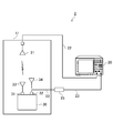
- FIG. 1 is a diagram showing a configuration of a reception sensitivity measurement system (hereinafter simply referred to as “measurement system”) 1 used in the reception sensitivity measurement method according to the present embodiment.
- FIG. 2 is a flowchart showing a procedure of the reception sensitivity measuring method according to the present embodiment.
- This measurement system 1 is a system for measuring the reception sensitivity of a MIMO communication apparatus 30 having a plurality of antennas, and in particular, can eliminate spatial correlation and perform reception sensitivity evaluation including the effects of self-poisoning. It is a system that can.
- the measurement system 1 is constructed (setup). For this reason, first, in order to connect the anechoic chamber 10, the test signal generator 20, the transmission antenna 21, the attenuator 25, the MIMO communication apparatus 30 as the device under test, and each device constituting the measurement system 1. Coaxial cables 22 and 23 are prepared.
- the inner surface of the anechoic chamber 10 that accommodates the MIMO communication apparatus 30 and the like is covered with a plurality of electromagnetic wave absorbers 10a that prevent the generation of reflected waves, is shielded from external noise, and has a radio wave inside. Provide a non-reflective environment without reflection.
- the test signal generator 20 outputs a plurality of systems of test signals.
- a standard signal generator (signal generator) is preferably used.
- the attenuator 25 is for simulating space loss and antenna gain.
- connection step S110 one end of the coaxial cable 22 is connected to one output terminal of the test signal generator 20.
- the other end of the coaxial cable 22 is drawn into the anechoic chamber 10 and connected to the set transmission antenna 21. Therefore, one output terminal of the test signal generator 20 is connected to the transmission antenna 21 through the coaxial cable 22.
- one end of the coaxial cable 23 is connected to the other output terminal of the test signal generator 20.
- the other end of the coaxial cable 23 is drawn into the anechoic chamber 10 and connected to the feeding point 32 of the MIMO communication apparatus 30.
- An attenuator 25 is attached in the middle of the coaxial cable 23. Therefore, the other output terminal of the test signal generator 20 is connected to the feeding point 32 of the MIMO communication apparatus 30 via the coaxial cable 23 and the attenuator 25.
- the MIMO communication apparatus 30 has two feeding points 31 and 32 to which two receiving antennas 33 and 34 are respectively attached.
- a receiving antenna 33 that receives a radio wave (test signal) from the transmitting antenna 21 is attached to one of the feeding points 31 and 32.
- the receiving antenna 34 is removed from the other feeding point 32.
- the feeding point 32 is connected to the other end of the coaxial cable 23 described above instead of the receiving antenna 34. Therefore, of the two test signal sequences output from the test signal generator 20, one test signal sequence is input to the MIMO communication apparatus 30 by radio and the other test signal sequence is wired.
- the reception sensitivity of the MIMO communication apparatus 30 is measured (measurement step S120).
- the reception sensitivity is defined as a minimum input signal for ensuring the quality of a reception signal required for a wireless system. For example, BER (bit error rate) or FER (frame error rate) Measured as a pair of quality evaluation index and input signal strength.
- the reception sensitivity is evaluated by measuring the input signal strength at which the BER or FER is equal to or higher than a predetermined value.
- a test signal for test is transmitted from the transmission antenna 21 to the reception antenna 33 of the MIMO communication apparatus 30 and the test signal is transmitted through the coaxial cable 23.
- the minimum power required to perform a predetermined function for example, the power at which the BER is equal to or higher than a predetermined value is measured. That is, one of the two test signal sequences output from the test signal generator 20 is transmitted wirelessly by the transmitting antenna 21 and the other test signal sequence is transmitted through the coaxial cable 23 (by wire).
- the reception sensitivity of the MIMO communication apparatus 30 is measured.
- the receiving antenna 33 is connected to one of the two feeding points 31 and 32 included in the MIMO communication apparatus 30, and the coaxial cable 23 is connected to the other feeding point 32.
- the Of the two test signal sequences one test signal sequence is input to the MIMO communication apparatus 30 wirelessly, and the other test signal sequence is wired. Therefore, the test signals are not mixed and the spatial correlation can be eliminated (that is, the test signals can be separated). Further, since one test signal series is received through the receiving antenna 33, it is possible to confirm the influence of noise generated from the MIMO communication apparatus 30 itself on the reception sensitivity, that is, the influence of self-poisoning. As a result, spatial correlation can be eliminated, and reception sensitivity evaluation including the effects of self-poisoning can be performed.
- the effect of noise countermeasures can be evaluated by measuring and comparing the reception sensitivity before and after the countermeasures.
- the MIMO communication apparatus 30 since the MIMO communication apparatus 30 is arranged in the anechoic chamber 10 in the arrangement step S100, in a non-reflective environment that is shielded from external noise and has no internal reflection of radio waves, The reception sensitivity of the MIMO communication apparatus 30 can be accurately measured. Further, according to the present embodiment, since the attenuator 25 is inserted in the middle of the coaxial cable 23 in the connection step S110, the attenuation of the attenuator 25 is adjusted to simulate the space loss and the antenna gain. Can do.
- FIG. 2 is a diagram illustrating a configuration of the measurement system 2 used in the reception sensitivity measurement method according to the second embodiment. Since the other configuration and the method of measuring the reception sensitivity are the same as those in the first embodiment described above, detailed description thereof is omitted here.
- the same effect as that of the first embodiment described above can be obtained.
- the anechoic box 11 by using the anechoic box 11, it is possible to measure the reception sensitivity with a smaller facility.
- the transmission antenna 21 and the MIMO communication apparatus 30 are arranged in the anechoic chamber 10, but as shown in FIG.
- the MIMO communication apparatus 30 may be arranged in a TEM (Transverse Electromagnetic) cell (or GTEM (Higa-hertz TEM) cell) 12 that can be kept at a high level, and reception sensitivity may be measured.
- FIG. 3 is a diagram illustrating a configuration of the measurement system 3 used in the reception sensitivity measurement method according to the third embodiment.
- one end of the coaxial cable 22 is connected to one output terminal of the test signal generator 20 in the connection step S110.
- the other end of the coaxial cable 22 is connected to a coaxial connector 26 attached to the tip of the quadrangular pyramid TEM cell 12. Therefore, when the TEM cell 12 is used, the transmission antenna 21 is not necessary. Since the other configuration and the method of measuring the reception sensitivity are the same as those in the first embodiment described above, detailed description thereof is omitted here.
- the same effect as that of the first embodiment described above can be obtained. Further, according to the present embodiment, by using the TEM cell 12, it is possible to measure the reception sensitivity with a further small facility.
- the present invention is not limited to the above-described embodiments, and various modifications can be made.
- the MIMO communication apparatus 30 having two power supply points 31 and 32 has been described as an example.
- the number of power supply points of the MIMO communication apparatus 30 is not limited to two, but three.
- the receiving antenna is attached to one feeding point, and a coaxial cable is connected to the other feeding point.
- a receiving antenna is attached to one feeding point, and a coaxial cable is connected to each of the other three feeding points.
Landscapes
- Engineering & Computer Science (AREA)
- Computer Networks & Wireless Communication (AREA)
- Signal Processing (AREA)
- Physics & Mathematics (AREA)
- Electromagnetism (AREA)
- Monitoring And Testing Of Transmission In General (AREA)
Abstract
MIMO通信装置の受信感度を測定する受信感度測定方法において、空間相関を無くすことができ、かつ、自家中毒の影響を含めた受信感度評価を行うことが可能な受信感度測定方法を提供する。 受信感度測定方法は、MIMO通信装置(30)を電波暗室(10)の中に配置する配置ステップS100と、MIMO通信装置(30)の2つの給電点(31,32)のうち、一方の給電点(31)に対して試験信号を受信するための受信アンテナ(33)を接続し、他方の給電点(32)に対して試験信号が伝送される同軸ケーブル(23)をアッテネータ(25)を介して接続する接続ステップS110と、受信アンテナ(33)に対して試験信号を送信するとともに、同軸ケーブル(23)を通して試験信号を伝送して、MIMO通信装置(30)の受信感度を測定する測定ステップS120とを備える。
Description
本発明は、受信感度測定方法に関し、特に、MIMO(Multiple Input Multiple Output)通信装置の受信感度を測定する受信感度測定方法に関する。
近年、無線LAN等の分野では、高速伝送を実現するMIMO通信方式が実用化されている。MIMO通信方式は、送受信局に複数のアンテナを装備し、同一周波数で複数の信号系列を空間多重して同時に伝送するため、アンテナ数に比例して伝送容量を増大することができる。
ところで、従来から、無線通信システムの評価実験には、有線実験と無線実験とが用いられている。有線実験は、送信機と受信機とを同軸ケーブルで接続し、無線信号の減衰量を擬似した送信信号を受信機に入力することによって試験を行う。これに対し、無線実験は、送信機から受信機に対して実際に電波を送信することによって試験を行う。
無線実験では、通常、MIMO通信装置が備えるアンテナ間の距離と比較して、MIMO通信装置(受信アンテナ)と測定器の送信アンテナとの距離が充分に大きくなる。そのため、MIMO通信装置の受信感度を、上述した無線実験で測定しようとした場合、複数の送信アンテナから出力された試験信号が伝搬中に混ざり合い(すなわち空間相関が高くなり)分離できなくなる。
ここで、特許文献1には、MIMO無線機と測定器とを有線で接続するとともに、該MIMO無線機と測定器間にMIMO試験装置を挿入し、実環境に近い伝送路条件を模擬的に作り出すシステムが開示されている。より詳細には、MIMO試験装置は、送信機のアンテナ端子に接続される3つの入力端子と、受信機のアンテナ端子に接続される3つの出力端子と、入力端子のそれぞれに接続され、入力端子から入力される信号を3つの信号に分配する分配器と、出力端子のそれぞれに接続され、分配器から入力される信号を合成し、合成された信号を出力端子に入力する合成器と、分配器と合成器との経路上に設けられた移相器とを備える。
このMIMO試験装置によれば、分配器と合成器とを介して3つの入力端子と3つの出力端子とを接続することにより、各アンテナから送信された信号が3つのアンテナで受信されるMIMO無線機の実使用環境に近い伝送路条件を擬似的に作り出すことができる。また、分配器から合成器の経路上にその通過特性を変える移相器を設けることにより、実環境で起こり得る伝送路条件の変化を擬似的に作り出すことができる。なお、試験環境では、無線通信を使う代わりに、データを送信するMIMO送信機であるAP(Access Point)と、MIMO受信機として動作するSTA(Station)が有線で接続され、その接続系路上に上述したMIMO試験装置が設けられる。
ところで、近年、携帯電子機器を構成する無線通信回路と情報処理回路の高密度化などに伴い、携帯電子機器内のLSIや電源回路などで発生した電磁ノイズがアンテナを経由して受信回路に混入し、受信感度を劣化させる現象、所謂自家中毒が問題になっている。例えば、携帯電話機では、LSIやDC-DCコンバータなどを発生源とする電磁ノイズが、無線信号の受信回路に混入して、ビット誤り率(BER:bit error rate)を増大させ、受信感度が低下するという現象が起きている。
しかしながら、上述したように、特許文献1記載の試験装置では、APとSTA(MIMO通信装置)とがMIMO試験装置を介して有線で接続されているため、MIMO通信装置自身から発生するノイズが、受信感度などの通信品質にどの程度影響を与えているかを評価することができない。
本発明は、上記問題点を解消する為になされたものであり、MIMO通信装置の受信感度を測定する受信感度測定方法であって、空間相関を無くすことができ、かつ、自家中毒の影響を含めた受信感度評価を行うことが可能な受信感度測定方法を提供することを目的とする。
本発明に係る受信感度測定方法は、複数のアンテナを備えるMIMO通信装置の受信感度を測定する受信感度測定方法であって、MIMO通信装置を、外部ノイズから遮断され、かつ内部では電波の反射がない無反射系の環境に配置する配置ステップと、複数のアンテナが接続される複数の給電点のうち、1つの給電点に対して試験信号を受信するためのアンテナを接続し、該給電点以外の各給電点に対して試験信号が伝送されるケーブルを接続する接続ステップと、1つの上記アンテナに対して試験信号を送信するとともに、ケーブルを通して試験信号を伝送して、MIMO通信装置の受信感度を測定する測定ステップとを備えることを特徴とする。
本発明に係る受信感度測定方法によれば、MIMO通信装置が備える複数の給電点のうち、1つの給電点にはアンテナが接続され、それ以外の給電点にはケーブルが接続される。そして、複数の試験信号系列のうち、1つの試験信号系列は無線で、その他の試験信号系列は有線でMIMO通信装置に入力される。そのため、各試験信号が混ざり合うことがなく、空間相関を無くすことができる(すなわち各試験信号を分離することができる)。また、1つの試験信号系列は、アンテナを通して受信されるため、MIMO通信装置自身から発生するノイズの受信感度に対する影響、すなわち自家中毒の影響を確認することができる。その結果、空間相関を無くすことができ、かつ、自家中毒の影響を含めた受信感度評価を行うことが可能となる。
本発明に係る受信感度測定方法では、接続ステップにおいて、ケーブルの途中に、アッテネータを挿入することが好ましい。
このようにすれば、アッテネータの減衰量を調節することにより、空間ロス及びアンテナのゲインを模擬することができる。
本発明に係る受信感度測定方法では、上記配置ステップにおいて、MIMO通信装置を、電波暗室、電波暗箱、或いは、TEMセルの中に配置することが好ましい。
このようにすれば、外部ノイズから遮断され、かつ内部では電波の反射がない無反射系の環境において、より正確にMIMO通信装置の受信感度を測定することができる。また、電波暗室やTEMセルを用いる場合には、より小型の設備で受信感度の測定を行うことができる。
本発明によれば、MIMO通信装置の受信感度を測定する受信感度測定方法において、空間相関を無くすことができ、かつ、自家中毒の影響を含めた受信感度評価を行うことが可能となる。
以下、図面を参照して本発明の好適な実施形態について詳細に説明する。なお、各図において、同一要素には同一符号を付して重複する説明を省略する。
(第1実施形態)
図1及び図2を併せて参照しつつ、第1実施形態に係る受信感度測定方法について説明する。図1は、本実施形態に係る受信感度測定方法で用いる受信感度測定システム(以下、単に「測定システム」という)1の構成を示す図である。図2は、本実施形態に係る受信感度測定方法の手順を示すフローチャートである。
図1及び図2を併せて参照しつつ、第1実施形態に係る受信感度測定方法について説明する。図1は、本実施形態に係る受信感度測定方法で用いる受信感度測定システム(以下、単に「測定システム」という)1の構成を示す図である。図2は、本実施形態に係る受信感度測定方法の手順を示すフローチャートである。
この測定システム1は、複数のアンテナを備えるMIMO通信装置30の受信感度を測定するシステムであり、特に、空間相関を無くすことができ、かつ、自家中毒の影響を含めた受信感度評価を行うことができるシステムである。
本実施形態に係る受信感度測定方法の実施に際しては、まず、測定システム1の構築(セットアップ)が行われる。そのため、先ず始めに、測定システム1を構成する、電波暗室10を初め、試験信号発生器20、送信アンテナ21、アッテネータ25、被測定物となるMIMO通信装置30、及び、各機器を接続するための同軸ケーブル22,23などが用意される。
ここで、MIMO通信装置30などを収容する電波暗室10は、その内面が、反射波の発生を防止する複数の電波吸収体10aによって覆われており、外部ノイズから遮断され、かつ内部では電波の反射がない無反射系の環境を提供する。試験信号発生器20は、複数系統の試験信号を出力するものであり、例えば標準信号発生器(シグナル・ジェネレータ)などが好適に用いられる。また、アッテネータ25は、空間ロス及びアンテナのゲインを模擬するためのものである。
[配置ステップS100]
上述した設備や機器類の用意が整うと、次に、被測定物であるMIMO通信装置30、及び、試験信号を送出する送信アンテナ21などが、電波暗室10の中の所定の位置に配置される(配置ステップS100)。なお、送信アンテナ21は、MIMO通信装置30から規定距離だけ離れた位置に設置される。また、試験信号発生器20が、電波暗室10の周囲の所定の位置に置かれる。
上述した設備や機器類の用意が整うと、次に、被測定物であるMIMO通信装置30、及び、試験信号を送出する送信アンテナ21などが、電波暗室10の中の所定の位置に配置される(配置ステップS100)。なお、送信アンテナ21は、MIMO通信装置30から規定距離だけ離れた位置に設置される。また、試験信号発生器20が、電波暗室10の周囲の所定の位置に置かれる。
[接続ステップS110]
次に、接続ステップS110では、試験信号発生器20の一方の出力端子に同軸ケーブル22の一端が接続される。この同軸ケーブル22の他端は、電波暗室10の中へ引き込まれ、セットされている送信アンテナ21に接続される。よって、試験信号発生器20の一方の出力端子は、同軸ケーブル22を通して、送信アンテナ21と接続される。
次に、接続ステップS110では、試験信号発生器20の一方の出力端子に同軸ケーブル22の一端が接続される。この同軸ケーブル22の他端は、電波暗室10の中へ引き込まれ、セットされている送信アンテナ21に接続される。よって、試験信号発生器20の一方の出力端子は、同軸ケーブル22を通して、送信アンテナ21と接続される。
また、試験信号発生器20の他方の出力端子に同軸ケーブル23の一端が接続される。この同軸ケーブル23の他端は、電波暗室10の中へ引き込まれ、MIMO通信装置30の給電点32に接続される。また、同軸ケーブル23の途中には、アッテネータ25が取り付けられる。よって、試験信号発生器20の他方の出力端子は、同軸ケーブル23及びアッテネータ25を介して、MIMO通信装置30の給電点32と接続される。
MIMO通信装置30は、2本の受信アンテナ33,34それぞれが取り付けられる2つの給電点31,32を有している。これらの給電点31,32のうち、一方の給電点31には、送信アンテナ21からの電波(試験信号)を受信する受信アンテナ33が取り付けられる。他方の給電点32からは受信アンテナ34が取り外される。そして、この給電点32には、受信アンテナ34の代わりに、上述した同軸ケーブル23の他端が接続される。よって、試験信号発生器20から出力される2系統の試験信号系列のうち、一方の試験信号系列は無線で、他方の試験信号系列は有線でMIMO通信装置30に入力される。
[測定ステップ120]
測定システム1のセットアップが完了した後、MIMO通信装置30の受信感度の測定が行われる(測定ステップS120)。ここで、外来ノイズレベルの十分に低い環境では、受信感度が高いほど弱い電波が受信可能である。受信感度は、無線システムに必要とされる受信信号の品質を確保するための最小入力信号として定義され、例えば、BER(bit error rate:ビット誤り率)やFER(flame error rate:フレーム誤り率)などの品質評価指標と入力信号強度の対として測定される。例えば、BERやFERが所定値以上になる入力信号強度を測定することにより、受信感度が評価される。
測定システム1のセットアップが完了した後、MIMO通信装置30の受信感度の測定が行われる(測定ステップS120)。ここで、外来ノイズレベルの十分に低い環境では、受信感度が高いほど弱い電波が受信可能である。受信感度は、無線システムに必要とされる受信信号の品質を確保するための最小入力信号として定義され、例えば、BER(bit error rate:ビット誤り率)やFER(flame error rate:フレーム誤り率)などの品質評価指標と入力信号強度の対として測定される。例えば、BERやFERが所定値以上になる入力信号強度を測定することにより、受信感度が評価される。
具体的には、MIMO通信装置30の受信感度を測定する際には、送信アンテナ21からMIMO通信装置30の受信アンテナ33に対してテスト用の試験信号を送出するとともに、同軸ケーブル23を通して試験信号をMIMO通信装置30に伝送し、所定の機能を果たすのに必要な最低電力、例えばBERが所定値以上になる電力を測定する。すなわち、試験信号発生器20から出力される2系統の試験信号系列のうち、一方の試験信号系列を、送信アンテナ21によって無線で送信するとともに、他方の試験信号系列を同軸ケーブル23を通して(有線で)伝送しつつ、ビットエラーをカウントし、徐々に試験信号発生器20の出力を低下させて、受信データのBERが所定値以上になる閾値を測定する。このようにして、MIMO通信装置30の受信感度が測定される。
本実施形態によれば、MIMO通信装置30が備える2つの給電点31,32のうち、一方の給電点31には受信アンテナ33が接続され、他方の給電点32には同軸ケーブル23が接続される。そして、2つの試験信号系列のうち、一方の試験信号系列は無線で、他方の試験信号系列は有線でMIMO通信装置30に入力される。そのため、各試験信号が混ざり合うことがなく、空間相関を無くすことができる(すなわち各試験信号を分離することができる)。また、一方の試験信号系列は、受信アンテナ33を通して受信されるため、MIMO通信装置30自身から発生するノイズの受信感度に対する影響、すなわち自家中毒の影響を確認することができる。その結果、空間相関を無くすことができ、かつ、自家中毒の影響を含めた受信感度評価を行うことが可能となる。
よって、MIMO通信装置30の開発において、自家中毒に対するノイズ対策を行う場合には、対策前と対策後の受信感度を測定して比較することにより、ノイズ対策の効果を評価することができる。
本実施形態によれば、配置ステップS100において、MIMO通信装置30が電波暗室10の中に配置されるため、外部ノイズから遮断され、かつ内部では電波の反射がない無反射系の環境において、より正確にMIMO通信装置30の受信感度を測定することができる。また、本実施形態によれば、接続ステップS110において、同軸ケーブル23の途中に、アッテネータ25が挿入されるため、アッテネータ25の減衰量を調節することにより、空間ロス及びアンテナのゲインを模擬することができる。
(第2実施形態)
上述した第1実施形態に係る受信感度測定方法では、送信アンテナ21及びMIMO通信装置30を電波暗室10の中に配置したが、図2に示すように、電波暗室10に代えて、送信アンテナ21及びMIMO通信装置30を電波暗箱11の中に配置して受信感度を測定することもできる。図2は、第2実施形態に係る受信感度測定方法で用いる測定システム2の構成を示す図である。その他の構成及び受信感度の測定の仕方は、上述した第1実施形態と同一であるため、ここでは詳細な説明を省略する。
上述した第1実施形態に係る受信感度測定方法では、送信アンテナ21及びMIMO通信装置30を電波暗室10の中に配置したが、図2に示すように、電波暗室10に代えて、送信アンテナ21及びMIMO通信装置30を電波暗箱11の中に配置して受信感度を測定することもできる。図2は、第2実施形態に係る受信感度測定方法で用いる測定システム2の構成を示す図である。その他の構成及び受信感度の測定の仕方は、上述した第1実施形態と同一であるため、ここでは詳細な説明を省略する。
本実施形態によっても、上述した第1実施形態と同様の効果を得ることができる。また、本実施形態によれば、電波暗箱11を用いることにより、より小型の設備で受信感度の測定を行うことができる。
(第3実施形態)
上述した第1実施形態に係る受信感度測定方法では、送信アンテナ21及びMIMO通信装置30を電波暗室10の中に配置したが、図3に示すように、電波暗室10に代えて、電界を均一に保つことができるTEM(Transverse Electromagnetic)セル(又はGTEM(Giga-hertz TEM)セル)12の中にMIMO通信装置30を配置して受信感度を測定してもよい。図3は、第3実施形態に係る受信感度測定方法で用いる測定システム3の構成を示す図である。
上述した第1実施形態に係る受信感度測定方法では、送信アンテナ21及びMIMO通信装置30を電波暗室10の中に配置したが、図3に示すように、電波暗室10に代えて、電界を均一に保つことができるTEM(Transverse Electromagnetic)セル(又はGTEM(Giga-hertz TEM)セル)12の中にMIMO通信装置30を配置して受信感度を測定してもよい。図3は、第3実施形態に係る受信感度測定方法で用いる測定システム3の構成を示す図である。
TEMセル12を用いる場合、接続ステップS110では、試験信号発生器20の一方の出力端子に同軸ケーブル22の一端が接続される。この同軸ケーブル22の他端は、四角錐状のTEMセル12の先端部に取り付けられた同軸コネクタ26に接続される。よって、TEMセル12を用いる場合には、送信アンテナ21は不要である。その他の構成及び受信感度の測定の仕方は、上述した第1実施形態と同一であるため、ここでは詳細な説明を省略する。
本実施形態によっても、上述した第1実施形態と同様の効果を得ることができる。また、本実施形態によれば、TEMセル12を用いることにより、さらに小型の設備で受信感度の測定を行うことができる。
以上、本発明の実施の形態について説明したが、本発明は、上記実施形態に限定されるものではなく種々の変形が可能である。例えば、上記実施形態では、2つの給電点31,32を有するMIMO通信装置30を例にして説明したが、MIMO通信装置30の給電点の数は、2個に限られることはなく、3個以上であってもよい、その場合、1つの給電点に受信アンテナが取り付けられ、その他の給電点には同軸ケーブルが接続される。例えば、4つの給電点を有するMIMO通信装置の場合には、1つの給電点には受信アンテナが取り付けられ、その他の3つの給電点にはそれぞれ同軸ケーブルが接続される。
1,2,3 測定システム
10 電波暗室
11 電波暗箱
12 TEMセル
20 試験信号発生器
21 送信アンテナ
22,23 同軸ケーブル
25 アッテネータ
30 MIMO通信装置
31,32 給電点
33 受信アンテナ
10 電波暗室
11 電波暗箱
12 TEMセル
20 試験信号発生器
21 送信アンテナ
22,23 同軸ケーブル
25 アッテネータ
30 MIMO通信装置
31,32 給電点
33 受信アンテナ
Claims (5)
- 複数のアンテナを備えるMIMO通信装置の受信感度を測定する受信感度測定方法であって、
前記MIMO通信装置を、外部ノイズから遮断され、かつ内部では電波の反射がない無反射系の環境に配置する配置ステップと、
前記複数のアンテナが接続される複数の給電点のうち、1つの給電点に対して試験信号を受信するためのアンテナを接続し、該給電点以外の各給電点に対して試験信号が伝送されるケーブルを接続する接続ステップと、
1つの前記アンテナに対して試験信号を送信するとともに、前記ケーブルを通して試験信号を伝送して、前記MIMO通信装置の受信感度を測定する測定ステップと、を備えることを特徴とする受信感度測定方法。 - 前記接続ステップでは、前記ケーブルの途中に、アッテネータを挿入することを特徴とする請求項1に記載の受信感度測定方法。
- 前記配置ステップでは、前記MIMO通信装置を、電波暗室の中に配置することを特徴とする請求項1又は2に記載の受信感度測定方法。
- 前記配置ステップでは、前記MIMO通信装置を、電波暗箱の中に配置することを特徴とする請求項1又は2に記載の受信感度測定方法。
- 前記配置ステップでは、前記MIMO通信装置を、TEMセルの中に配置することを特徴とする請求項1又は2に記載の受信感度測定方法。
Priority Applications (1)
| Application Number | Priority Date | Filing Date | Title |
|---|---|---|---|
| JP2012556766A JP5786871B2 (ja) | 2011-02-08 | 2012-01-17 | 受信感度測定方法 |
Applications Claiming Priority (2)
| Application Number | Priority Date | Filing Date | Title |
|---|---|---|---|
| JP2011025116 | 2011-02-08 | ||
| JP2011-025116 | 2011-02-08 |
Publications (1)
| Publication Number | Publication Date |
|---|---|
| WO2012108124A1 true WO2012108124A1 (ja) | 2012-08-16 |
Family
ID=46638352
Family Applications (1)
| Application Number | Title | Priority Date | Filing Date |
|---|---|---|---|
| PCT/JP2012/000232 Ceased WO2012108124A1 (ja) | 2011-02-08 | 2012-01-17 | 受信感度測定方法 |
Country Status (2)
| Country | Link |
|---|---|
| JP (1) | JP5786871B2 (ja) |
| WO (1) | WO2012108124A1 (ja) |
Cited By (3)
| Publication number | Priority date | Publication date | Assignee | Title |
|---|---|---|---|---|
| JP2016178525A (ja) * | 2015-03-20 | 2016-10-06 | アンリツ株式会社 | Mimoシステム試験装置およびそのチャネル相関情報設定方法 |
| WO2020174959A1 (ja) * | 2019-02-28 | 2020-09-03 | 株式会社村田製作所 | 通信装置の受信感度測定方法およびそれを用いた通信装置のノイズ対策効果評価方法 |
| US11558131B2 (en) * | 2018-01-12 | 2023-01-17 | General Test Systems Inc. | Method and apparatus for measuring wireless performance of receiver of wireless terminal |
Citations (4)
| Publication number | Priority date | Publication date | Assignee | Title |
|---|---|---|---|---|
| JP2007294903A (ja) * | 2006-03-31 | 2007-11-08 | Nitta Ind Corp | 遮蔽継ぎ構造および空間形成体、空間形成体を用いる試験方法 |
| JP2008263406A (ja) * | 2007-04-12 | 2008-10-30 | Matsushita Electric Ind Co Ltd | 試験装置 |
| JP2009049966A (ja) * | 2007-07-25 | 2009-03-05 | Panasonic Corp | 無線評価装置 |
| JP2010117275A (ja) * | 2008-11-13 | 2010-05-27 | Ntt Docomo Inc | マルチアンテナ測定システム |
Family Cites Families (5)
| Publication number | Priority date | Publication date | Assignee | Title |
|---|---|---|---|---|
| JP2738507B2 (ja) * | 1994-10-25 | 1998-04-08 | 松下電器産業株式会社 | 微小電磁波測定および強電磁波発生用セル |
| JP3307309B2 (ja) * | 1997-12-24 | 2002-07-24 | 三菱電機株式会社 | 無線端末用試験装置および無線端末用電波環境試験装置 |
| JP4038440B2 (ja) * | 2003-02-21 | 2008-01-23 | 株式会社エヌ・ティ・ティ・ドコモ | マルチパス生成装置、多重波フェージングシミュレータ及びマルチパス生成方法 |
| CN101652898A (zh) * | 2007-02-28 | 2010-02-17 | 日本电气株式会社 | 阵列天线、无线通信设备和阵列天线控制方法 |
| JP5494911B2 (ja) * | 2009-02-16 | 2014-05-21 | 日本電気株式会社 | リングオシレータ |
-
2012
- 2012-01-17 JP JP2012556766A patent/JP5786871B2/ja not_active Expired - Fee Related
- 2012-01-17 WO PCT/JP2012/000232 patent/WO2012108124A1/ja not_active Ceased
Patent Citations (4)
| Publication number | Priority date | Publication date | Assignee | Title |
|---|---|---|---|---|
| JP2007294903A (ja) * | 2006-03-31 | 2007-11-08 | Nitta Ind Corp | 遮蔽継ぎ構造および空間形成体、空間形成体を用いる試験方法 |
| JP2008263406A (ja) * | 2007-04-12 | 2008-10-30 | Matsushita Electric Ind Co Ltd | 試験装置 |
| JP2009049966A (ja) * | 2007-07-25 | 2009-03-05 | Panasonic Corp | 無線評価装置 |
| JP2010117275A (ja) * | 2008-11-13 | 2010-05-27 | Ntt Docomo Inc | マルチアンテナ測定システム |
Cited By (6)
| Publication number | Priority date | Publication date | Assignee | Title |
|---|---|---|---|---|
| JP2016178525A (ja) * | 2015-03-20 | 2016-10-06 | アンリツ株式会社 | Mimoシステム試験装置およびそのチャネル相関情報設定方法 |
| US11558131B2 (en) * | 2018-01-12 | 2023-01-17 | General Test Systems Inc. | Method and apparatus for measuring wireless performance of receiver of wireless terminal |
| WO2020174959A1 (ja) * | 2019-02-28 | 2020-09-03 | 株式会社村田製作所 | 通信装置の受信感度測定方法およびそれを用いた通信装置のノイズ対策効果評価方法 |
| JPWO2020174959A1 (ja) * | 2019-02-28 | 2021-11-04 | 株式会社村田製作所 | 通信装置の受信感度測定方法およびそれを用いた通信装置のノイズ対策効果評価方法 |
| JP7063412B2 (ja) | 2019-02-28 | 2022-05-09 | 株式会社村田製作所 | 通信装置の受信感度測定方法およびそれを用いた通信装置のノイズ対策効果評価方法 |
| US11757546B2 (en) | 2019-02-28 | 2023-09-12 | Murata Manufacturing Co., Ltd. | Communication device reception sensitivity measurement method and communication device noise control effect evaluation method using the same |
Also Published As
| Publication number | Publication date |
|---|---|
| JPWO2012108124A1 (ja) | 2014-07-03 |
| JP5786871B2 (ja) | 2015-09-30 |
Similar Documents
| Publication | Publication Date | Title |
|---|---|---|
| CN103856272B (zh) | Mimo无线终端的无线性能测试方法 | |
| EP2533572B1 (en) | Method and system for testing over the air performances in multi-antenna system | |
| EP3890199B1 (en) | Method and system for testing wireless performance of wireless terminal | |
| CN105008942B (zh) | 使用无线测试信号测试射频无线信号收发器的系统和方法 | |
| US8954014B2 (en) | Over-the air test | |
| US20140266930A1 (en) | System and method for testing radio frequency wireless signal transceivers using wireless test signals | |
| CN107800495A (zh) | 用于多入多出无线链路的无线电信道仿真的系统和方法 | |
| CN101667873B (zh) | 一种多天线信道环境下接收机射频性能的测试方法和系统 | |
| KR20160018560A (ko) | 무선 테스트 신호를 이용한 무선 주파수 무선 신호 트랜시버용 시스템 및 방법 | |
| EP3444623B1 (en) | Distributed system for radio frequency environment simulation | |
| KR20160018573A (ko) | 무선 테스트 신호를 이용한 무선 주파수 무선 신호 트랜시버용 시스템 및 방법 | |
| KR20160016865A (ko) | 무선 테스트 신호를 이용한 무선 주파수 무선 신호 트랜시버용 시스템 및 방법 | |
| US20150111507A1 (en) | Millimeter wave conductive setup | |
| JP5786871B2 (ja) | 受信感度測定方法 | |
| WO2011097900A1 (zh) | 基于多天线系统的空间射频性能测试方法及系统 | |
| JP2012134905A (ja) | 受信感度簡易評価システム及びその方法 | |
| EP3523893B1 (en) | Method and radio network node for determining total radiated power from a plurality of antennas | |
| CN110514907B (zh) | 无线通信装置空中传输量测系统 | |
| Li et al. | Total isotropic sensitivity measurement in switched beam antenna systems | |
| Del Barrio et al. | Correlation evaluation on small LTE handsets | |
| JP7063412B2 (ja) | 通信装置の受信感度測定方法およびそれを用いた通信装置のノイズ対策効果評価方法 | |
| CN106850095B (zh) | X波段月球探测器通信接收与发射兼容性测试和分析方法 | |
| CN105897348A (zh) | 剩余无源互调测试方法 | |
| JP2022545932A (ja) | アンテナ較正装置およびアンテナ較正方法 | |
| WO2024234373A1 (en) | A test method for ecc calculation based on ota 2 tx trp measurement |
Legal Events
| Date | Code | Title | Description |
|---|---|---|---|
| 121 | Ep: the epo has been informed by wipo that ep was designated in this application |
Ref document number: 12744562 Country of ref document: EP Kind code of ref document: A1 |
|
| ENP | Entry into the national phase |
Ref document number: 2012556766 Country of ref document: JP Kind code of ref document: A |
|
| NENP | Non-entry into the national phase |
Ref country code: DE |
|
| 122 | Ep: pct application non-entry in european phase |
Ref document number: 12744562 Country of ref document: EP Kind code of ref document: A1 |