WO2012105448A1 - バッテリモジュール、バッテリシステム、電源装置、及び移動体 - Google Patents
バッテリモジュール、バッテリシステム、電源装置、及び移動体 Download PDFInfo
- Publication number
- WO2012105448A1 WO2012105448A1 PCT/JP2012/051831 JP2012051831W WO2012105448A1 WO 2012105448 A1 WO2012105448 A1 WO 2012105448A1 JP 2012051831 W JP2012051831 W JP 2012051831W WO 2012105448 A1 WO2012105448 A1 WO 2012105448A1
- Authority
- WO
- WIPO (PCT)
- Prior art keywords
- battery
- batteries
- series
- module
- control unit
- Prior art date
- Legal status (The legal status is an assumption and is not a legal conclusion. Google has not performed a legal analysis and makes no representation as to the accuracy of the status listed.)
- Ceased
Links
Images



Classifications
-
- H—ELECTRICITY
- H02—GENERATION; CONVERSION OR DISTRIBUTION OF ELECTRIC POWER
- H02J—ELECTRIC POWER NETWORKS; CIRCUIT ARRANGEMENTS OR SYSTEMS FOR SUPPLYING OR DISTRIBUTING ELECTRIC POWER; SYSTEMS FOR STORING ELECTRIC ENERGY
- H02J7/00—Circuit arrangements for charging or discharging batteries or for supplying loads from batteries
- H02J7/50—Circuit arrangements for charging or discharging batteries or for supplying loads from batteries acting upon multiple batteries simultaneously or sequentially
- H02J7/575—Parallel/serial switching of connection of batteries to charge or load circuit
-
- B—PERFORMING OPERATIONS; TRANSPORTING
- B60—VEHICLES IN GENERAL
- B60L—PROPULSION OF ELECTRICALLY-PROPELLED VEHICLES; SUPPLYING ELECTRIC POWER FOR AUXILIARY EQUIPMENT OF ELECTRICALLY-PROPELLED VEHICLES; ELECTRODYNAMIC BRAKE SYSTEMS FOR VEHICLES IN GENERAL; MAGNETIC SUSPENSION OR LEVITATION FOR VEHICLES; MONITORING OPERATING VARIABLES OF ELECTRICALLY-PROPELLED VEHICLES; ELECTRIC SAFETY DEVICES FOR ELECTRICALLY-PROPELLED VEHICLES
- B60L3/00—Electric devices on electrically-propelled vehicles for safety purposes; Monitoring operating variables, e.g. speed, deceleration or energy consumption
- B60L3/0023—Detecting, eliminating, remedying or compensating for drive train abnormalities, e.g. failures within the drive train
- B60L3/0046—Detecting, eliminating, remedying or compensating for drive train abnormalities, e.g. failures within the drive train relating to electric energy storage systems, e.g. batteries or capacitors
-
- B—PERFORMING OPERATIONS; TRANSPORTING
- B60—VEHICLES IN GENERAL
- B60L—PROPULSION OF ELECTRICALLY-PROPELLED VEHICLES; SUPPLYING ELECTRIC POWER FOR AUXILIARY EQUIPMENT OF ELECTRICALLY-PROPELLED VEHICLES; ELECTRODYNAMIC BRAKE SYSTEMS FOR VEHICLES IN GENERAL; MAGNETIC SUSPENSION OR LEVITATION FOR VEHICLES; MONITORING OPERATING VARIABLES OF ELECTRICALLY-PROPELLED VEHICLES; ELECTRIC SAFETY DEVICES FOR ELECTRICALLY-PROPELLED VEHICLES
- B60L50/00—Electric propulsion with power supplied within the vehicle
- B60L50/50—Electric propulsion with power supplied within the vehicle using propulsion power supplied by batteries or fuel cells
- B60L50/60—Electric propulsion with power supplied within the vehicle using propulsion power supplied by batteries or fuel cells using power supplied by batteries
- B60L50/66—Arrangements of batteries
-
- B—PERFORMING OPERATIONS; TRANSPORTING
- B60—VEHICLES IN GENERAL
- B60L—PROPULSION OF ELECTRICALLY-PROPELLED VEHICLES; SUPPLYING ELECTRIC POWER FOR AUXILIARY EQUIPMENT OF ELECTRICALLY-PROPELLED VEHICLES; ELECTRODYNAMIC BRAKE SYSTEMS FOR VEHICLES IN GENERAL; MAGNETIC SUSPENSION OR LEVITATION FOR VEHICLES; MONITORING OPERATING VARIABLES OF ELECTRICALLY-PROPELLED VEHICLES; ELECTRIC SAFETY DEVICES FOR ELECTRICALLY-PROPELLED VEHICLES
- B60L58/00—Methods or circuit arrangements for monitoring or controlling batteries or fuel cells, specially adapted for electric vehicles
- B60L58/10—Methods or circuit arrangements for monitoring or controlling batteries or fuel cells, specially adapted for electric vehicles for monitoring or controlling batteries
- B60L58/12—Methods or circuit arrangements for monitoring or controlling batteries or fuel cells, specially adapted for electric vehicles for monitoring or controlling batteries responding to state of charge [SoC]
-
- B—PERFORMING OPERATIONS; TRANSPORTING
- B60—VEHICLES IN GENERAL
- B60L—PROPULSION OF ELECTRICALLY-PROPELLED VEHICLES; SUPPLYING ELECTRIC POWER FOR AUXILIARY EQUIPMENT OF ELECTRICALLY-PROPELLED VEHICLES; ELECTRODYNAMIC BRAKE SYSTEMS FOR VEHICLES IN GENERAL; MAGNETIC SUSPENSION OR LEVITATION FOR VEHICLES; MONITORING OPERATING VARIABLES OF ELECTRICALLY-PROPELLED VEHICLES; ELECTRIC SAFETY DEVICES FOR ELECTRICALLY-PROPELLED VEHICLES
- B60L58/00—Methods or circuit arrangements for monitoring or controlling batteries or fuel cells, specially adapted for electric vehicles
- B60L58/10—Methods or circuit arrangements for monitoring or controlling batteries or fuel cells, specially adapted for electric vehicles for monitoring or controlling batteries
- B60L58/18—Methods or circuit arrangements for monitoring or controlling batteries or fuel cells, specially adapted for electric vehicles for monitoring or controlling batteries of two or more battery modules
- B60L58/22—Balancing the charge of battery modules
-
- H—ELECTRICITY
- H01—ELECTRIC ELEMENTS
- H01M—PROCESSES OR MEANS, e.g. BATTERIES, FOR THE DIRECT CONVERSION OF CHEMICAL ENERGY INTO ELECTRICAL ENERGY
- H01M10/00—Secondary cells; Manufacture thereof
- H01M10/42—Methods or arrangements for servicing or maintenance of secondary cells or secondary half-cells
- H01M10/4207—Methods or arrangements for servicing or maintenance of secondary cells or secondary half-cells for several batteries or cells simultaneously or sequentially
-
- H—ELECTRICITY
- H02—GENERATION; CONVERSION OR DISTRIBUTION OF ELECTRIC POWER
- H02J—ELECTRIC POWER NETWORKS; CIRCUIT ARRANGEMENTS OR SYSTEMS FOR SUPPLYING OR DISTRIBUTING ELECTRIC POWER; SYSTEMS FOR STORING ELECTRIC ENERGY
- H02J7/00—Circuit arrangements for charging or discharging batteries or for supplying loads from batteries
- H02J7/50—Circuit arrangements for charging or discharging batteries or for supplying loads from batteries acting upon multiple batteries simultaneously or sequentially
- H02J7/52—Circuit arrangements for charging or discharging batteries or for supplying loads from batteries acting upon multiple batteries simultaneously or sequentially for charge balancing, e.g. equalisation of charge between batteries
- H02J7/54—Passive balancing, e.g. using resistors or parallel MOSFETs
-
- Y—GENERAL TAGGING OF NEW TECHNOLOGICAL DEVELOPMENTS; GENERAL TAGGING OF CROSS-SECTIONAL TECHNOLOGIES SPANNING OVER SEVERAL SECTIONS OF THE IPC; TECHNICAL SUBJECTS COVERED BY FORMER USPC CROSS-REFERENCE ART COLLECTIONS [XRACs] AND DIGESTS
- Y02—TECHNOLOGIES OR APPLICATIONS FOR MITIGATION OR ADAPTATION AGAINST CLIMATE CHANGE
- Y02E—REDUCTION OF GREENHOUSE GAS [GHG] EMISSIONS, RELATED TO ENERGY GENERATION, TRANSMISSION OR DISTRIBUTION
- Y02E60/00—Enabling technologies; Technologies with a potential or indirect contribution to GHG emissions mitigation
- Y02E60/10—Energy storage using batteries
-
- Y—GENERAL TAGGING OF NEW TECHNOLOGICAL DEVELOPMENTS; GENERAL TAGGING OF CROSS-SECTIONAL TECHNOLOGIES SPANNING OVER SEVERAL SECTIONS OF THE IPC; TECHNICAL SUBJECTS COVERED BY FORMER USPC CROSS-REFERENCE ART COLLECTIONS [XRACs] AND DIGESTS
- Y02—TECHNOLOGIES OR APPLICATIONS FOR MITIGATION OR ADAPTATION AGAINST CLIMATE CHANGE
- Y02T—CLIMATE CHANGE MITIGATION TECHNOLOGIES RELATED TO TRANSPORTATION
- Y02T10/00—Road transport of goods or passengers
- Y02T10/60—Other road transportation technologies with climate change mitigation effect
- Y02T10/70—Energy storage systems for electromobility, e.g. batteries
Definitions
- the present invention relates to a battery module, a battery system, a power supply device including the battery system, and a moving object including the battery system.
- a battery module having a configuration in which a battery group having a plurality of battery cells connected in parallel or a battery having a single battery cell is connected in series or a battery system having a configuration in which a plurality of battery modules are connected in series has been developed. ing.
- the battery module having a configuration in which the batteries are connected in series has a problem that the charge / discharge characteristics of the battery module are abnormal if one of the batteries is abnormal.
- a battery system having a configuration in which a plurality of battery modules are connected in series has a problem that an abnormality occurs in the charge / discharge characteristics of the battery system if any one of the battery modules is abnormal.
- Patent Document 1 An assembled battery (battery module) that can solve the above problems and can extend the life is disclosed in Patent Document 1.
- each cell constituting the assembled battery is connected in series, the abnormal cell in which a steady abnormality is detected is disconnected from the assembled battery, and a spare is used instead of the disconnected abnormal cell.
- the battery is connected to the battery pack.
- the assembled battery disclosed in Patent Document 1 since a spare battery is used instead of an abnormal cell, the battery life is reached when the number of abnormal cells exceeds the number of spare batteries, and each cell constituting the assembled battery The use time of the spare battery is extremely shortened compared to the use time. As described above, the assembled battery disclosed in Patent Document 1 is not configured to fully utilize a spare battery, and thus has a long life.
- the present invention includes a battery module capable of further extending the life, a battery system capable of further extending the life, a power supply device including the battery system, and the battery system.
- the object is to provide a moving body.
- the battery module according to the present invention includes (N + ⁇ ) batteries, (N + ⁇ ) detour switches, and compares the parameters associated with the batteries by comparing the N batteries. And controlling each of the detour switches to connect the N batteries in series and to disconnect the ⁇ batteries from the series circuit in which the N batteries are connected in series.
- the battery has a cell group in which a plurality of battery cells are connected in parallel or a single battery cell.
- the battery system includes (M + ⁇ ) battery modules, (M + ⁇ ) detour switches, and compares M parameters by comparing parameters associated with the battery modules.
- the battery module has a configuration in which a plurality of cell groups in which a plurality of battery cells are connected in parallel are connected in series, or a plurality of single battery cells are connected in series.
- a power supply apparatus includes a battery system having the above configuration and a power conversion unit connected between the battery system and an external system power supply.
- a mobile body according to the present invention is connected between the battery system having the above configuration, a motor driven by electric power output from the battery system, and the battery system and the motor. It is set as the structure provided with a power converter.
- the life of the battery module, the battery system, the power supply device, and the moving body can be further extended.
- the module control unit 14 corresponds to an example of a “control unit” described in claim 1.
- the module control unit 14 measures a state of charge (SOC) of each battery 11 and a calculation unit that calculates an SOC change rate ( ⁇ SOC) used for deterioration determination described later from the measured SOC.
- SOC state of charge
- ⁇ SOC SOC change rate
- 14 ⁇ / b> B and a selection unit 14 ⁇ / b> C that performs deterioration determination based on the value of ⁇ SOC and selects a reusable battery to be described later.
- a battery module (hereinafter abbreviated as “module”) 1 is a single unit and is connected to a load 2A through a switch SW1 and through a switch SW2. Used by being connected to the power supply 2B.
- the load 2A consumes electric power from various electronic devices and motors, and the power source 2B supplies electric power from a system power source and a generator to the outside.
- the module 1 discharges when connected to the load 2A, and charges when connected to the power source 2B. Therefore, charging / discharging of the module 1 can be switched depending on which of the switches SW1 and SW2 is turned on.
- the module 1 includes (N + ⁇ ) batteries 11 having a cell group in which a plurality of battery cells 11a are connected in parallel, includes (N + ⁇ ) detour switches 12, and includes an equalization unit 13 and a module.
- One module control unit 14 that performs one overall control is provided.
- N is a rated value necessary for supplying power to the load 2A or charging with power supplied from the power source 2B when the module 1 is connected to the load 2A or the power source 2B alone, and N and ⁇ are optional. Is a natural number.
- Each detour switch 12 corresponds to each battery 11, and connects the corresponding battery 11 to the load 2A or the power source 2B by connecting the terminal c and the terminal a connected to one end of the corresponding battery 11, or Whether the corresponding battery 11 is disconnected from the load 2A and the power source 2B by connecting the terminal c and the terminal b connected to the other end of the corresponding battery 11 via the detour path is controlled by the module control unit 14 Select accordingly.
- the batteries for which the corresponding bypass switch 12 selects the connection between the terminal c and the terminal a are connected in series and connected to the load 2 ⁇ / b> A or the power supply 2 ⁇ / b> B.
- the equalizing unit 13 has (N + ⁇ ) discharge circuits (not shown in FIG. 1). Each discharge circuit of the equalization unit 13 corresponds to each battery 11 and is connected to each battery 11 in parallel.
- FIG. 2B one structural example of the equalization part 13 is shown to FIG. 2B.
- each discharge circuit of the equalizing unit 13 includes a resistor R1 and a switch SW3 connected in series, and each discharge circuit corresponds to the battery 11 corresponding to when the switch SW3 is in the ON state. Is discharged.
- the SOC of each battery 11 can be equalized by adjusting the amount of discharge of each battery 11 by each discharge circuit so that the state of charge of each battery 11 is aligned.
- module 1 Next, the operation of module 1 will be described with reference to FIGS.
- the module control unit 14 When the module control unit 14 starts the operation flow shown in FIG. 3, the module control unit 14 first compares the parameters associated with each battery 11 at the timing when the module 1 is not charging / discharging, thereby detecting the abnormality detected battery ( Select a battery (hereinafter referred to as “deterioration detection battery”) ( ⁇ ) for which deterioration is detected from all the batteries (N + ⁇ ) excluding ⁇ (see step S56 described later) (step S1). .
- ⁇ is an integer from 0 to ⁇ .
- the parameter is the number of times the battery is connected in series
- the module control unit 14 stores the parameter, and the N batteries connected in series in order from the battery 11 having the smallest parameter value. It is said.
- the module control unit 14 sets a deterioration detection permission flag to 0 (not permitted) for each deterioration detection battery (step S1).
- the module control unit 14 controls each bypass switch 12 based on the selection, disconnects the abnormality detected battery ⁇ and the deterioration detected battery ( ⁇ ) from the load 2A and the power source 2B, and detects the abnormality.
- All N batteries other than the used battery and the deterioration detection battery are connected in series and connected to the load 2A or the power source 2B (step S2).
- the deterioration detection battery is selected by comparing the parameters associated with each battery 11, it is possible to prevent N batteries connected in series from being fixed. Thereby, the lifetime can be further increased as compared with the assembled battery disclosed in Patent Document 1.
- the module control unit 14 executes step S3 after step S2. In step S3, the module control unit 14 determines whether or not the SOC of the entire module, that is, the average SOC of all the batteries (N + ⁇ ) excluding the abnormally detected batteries ⁇ is less than 80%.
- step S3 If the SOC of the entire module is smaller than 80% (YES in step S3), the deterioration detection battery SOC adjustment process (step S4) and the deterioration determination process (step S5) are sequentially executed at the timing when the module 1 is charging / discharging. Then, the operation flow shown in FIG. Note that 80% in step S3 is an example, and an appropriate value may be set according to the specifications of the module 1 and the load 2A.
- the deterioration detection battery SOC adjustment process in step S4 is as shown in the operation flow in FIG.
- the module control unit 14 starts the operation flow shown in FIG. 4, first, whether or not each of the ( ⁇ ) deterioration detection batteries whose deterioration detection permission flag is set to 0 is in the first charge state. Is determined (step S41).
- the “first charging state” a state where the SOC of the battery is larger than 45% and smaller than 55% will be described as an example.
- the “first charging state” is a fully charged state. As long as it is not too close and not too close to a fully discharged state, the SOC of the battery may be other than a state of greater than 45% and less than 55%.
- the module control unit 14 determines whether or not the SOC is 55% or more for each deterioration detection battery determined to be negative in step S41 (step S42). Next, the module control unit 14 connects the deterioration detection battery that has not been determined to be negative in step S42 to the load 2A only during the period in which the module 1 is discharging (step S43). Alternatively, the module control unit 14 connects the deterioration detection battery determined to be negative in step S42 to the power source 2B only during the period when the module 1 is charging (step S44).
- the module control unit 14 determines whether the load 2A and the deterioration detection battery that has not been determined to be negative in step S41, even if the module 1 is discharging or the module 1 is charging.
- the battery is kept disconnected from the power source 2B, and the battery deterioration detection permission flag is set to 1 (permitted) (step S45).
- step S46 the module control unit 14 determines whether or not the deterioration detection flags of all deterioration detection batteries are 1 (step S46). If the deterioration detection flags of all the deterioration detection batteries are not 1 (NO in step S46), the process returns to step S41. On the other hand, if the deterioration detection flags of all the deterioration detection batteries are 1 (YES in step S46), the operation flow shown in FIG. When the operation flow shown in FIG. 4 is completed, the SOCs of all the ( ⁇ ) deterioration detection batteries are within the range of more than 45% and less than 55%.
- the deterioration determination process in step S5 is as shown in the operation flow in FIG.
- the module control unit 14 executes the processing of the operation flow shown in FIG. 5 in parallel for each deterioration detection battery.
- the module control unit 14 first calculates the SOC of the deterioration detection battery, and stores the calculation result as the initial SOC (step S51).
- step S52 the module control unit 14 starts discharging the deterioration detection battery and sets the time counter t to 0 and then starts time measurement using the time counter t.
- the discharge of the deterioration detection battery is performed using a discharge circuit corresponding to the deterioration detection battery in the equalization unit 13.
- step S53 the module control unit 14 determines whether or not the time counter t has reached a predetermined time T (for example, 24 hours) or more.
- a predetermined time T for example, 24 hours
- the module control unit 14 calculates the SOC of the deterioration detection battery again, and sets the calculated result as the SOC after the predetermined time has elapsed.
- the calculation unit 14B in the module control unit 14 calculates the SOC change rate ( ⁇ SOC) from the initial SOC and the SOC after a predetermined time has elapsed (step S54).
- ⁇ SOC is obtained by dividing the initial SOC obtained by subtracting the SOC after the elapse of a predetermined time by the time counter t when the SOC is calculated after the elapse of the predetermined time.
- step S55 the selection unit 14C in the module control unit 14 determines whether ⁇ SOC is smaller than the threshold value D (D is a positive constant). If ⁇ SOC is not smaller than threshold value D (NO in step S55), for example, there is a possibility of a slight short circuit between the positive electrode and the negative electrode in the battery cell, so that it is determined as abnormal and stored as an abnormally detected battery. Then (step S56), the operation flow of FIG. On the other hand, if ⁇ SOC is smaller than the threshold value D (YES in step S55), it is determined as normal, stored as a reusable battery (step S57), and the operation flow in FIG.
- D is a positive constant
- step S1 in the operation flow shown in FIG. 3 is started again.
- the current SOC average value of the N batteries connected in series with each other and connected to the load 2A or the power source 2B, and the current state It is determined whether or not the difference between the ( ⁇ ′) reuse target batteries and the average value of the SOC is smaller than a predetermined value.
- step S1 in the operation flow shown in FIG. 3 is executed again.
- the parameter is the number of times the battery is connected in series
- the module control unit 14 stores the parameter
- the battery 11 is connected in series starting from the battery 11 having the smallest parameter value. Since N batteries are used, each time the operation flow shown in FIG. 3 is executed, the batteries to be selected as the deterioration detection battery are sequentially different, and the deterioration detection battery is rotated. By this rotation, deterioration detection can be performed evenly, and variation between batteries in the usage time of all the batteries excluding abnormally detected batteries (the period when charging / discharging is connected to the load 2A or the power source 2B) is reduced. can do.
- the deterioration determination can be performed without stopping charging / discharging in a state where the module 1 is connected to the load 2A or the power source 2B, and preparation for the next rotation can be performed without delay.
- the difference between the average SOC of N batteries connected in series and the average SOC of ( ⁇ ′) reusable batteries is smaller than a predetermined value, The operation flow shown in FIG. 3 is repeated. Thereby, after step S1 in the operation flow shown in FIG. 3 is executed again, it is possible to prevent the SOCs of N batteries newly connected in series from greatly varying.
- the battery deterioration determination is performed using an equalization unit that is generally provided to equalize the SOC of each battery in the module. There is no need to provide a special circuit, and battery deterioration can be determined at low cost. Further, in the present embodiment, the preparation for performing the battery deterioration determination using the load 2A and the power source 2B without providing a special circuit for the preparation for the battery deterioration determination (see FIG. 4), the preparation for determining the deterioration of the battery can be realized at low cost.
- the deterioration degree of the battery can be determined with higher accuracy than the deterioration determination based on the analysis of the measured value during charging and discharging. Minute abnormality (deterioration) can be detected.
- the overall control unit 4 and the module control unit 14 correspond to an example of a “control unit” described in claim 4.
- the overall control unit 4 includes a selection unit 4A that selects an equalization target battery described later.
- the module control unit 14 measures the SOC of each battery 11 and a calculation unit 14B that calculates a difference between the maximum SOC SOC and the minimum SOC min of the battery 11 in the module 1 from the measured SOC. And have.
- a battery system including (M + ⁇ ) modules 1, (M + ⁇ ) detour switches 3, and one overall control unit 4 is connected to a load 2A via the switch SW1.
- the battery system according to the second embodiment of the present invention discharges when connected to the load 2A and charges when connected to the power source 2B. Therefore, charging / discharging of the battery system according to the second embodiment of the present invention can be switched depending on which of the switches SW1 and SW2 is turned on.
- FIG. 6 the same parts as those in FIG. 1 are denoted by the same reference numerals, and detailed description thereof is omitted.
- M is a rated value required for power supply to the load 2A or charging with power supplied from the power source 2B, and M and ⁇ are arbitrary natural numbers.
- Each detour switch 3 corresponds to each module 1, and connects the corresponding module 1 to the load 2A or the power source 2B by connecting the terminal f and the terminal d connected to one end of the corresponding module 1; Whether the corresponding module 1 is disconnected from the load 2A and the power source 2B by connecting the terminal f and the terminal e connected to the other end of the corresponding module 1 via a detour path is controlled by the overall control unit 4 Select accordingly.
- the modules for which the corresponding detour switch 3 selects the connection between the terminal f and the terminal d are connected in series to each other and connected to the load 2A or the power supply 2B.
- the parameter associated with each module 1 is the difference between the maximum SOC value SOCmax of the battery 11 in the module and the minimum SOC value SOCmin of the battery 11 in the module.
- the above parameters are stored every time.
- the overall control unit 4 first controls the measurement units 14A in all the module (M + ⁇ ) module control units 14 excluding the abnormally detected module ⁇ , For all modules (M + ⁇ ) excluding ⁇ detected abnormality modules, the SOC of each battery 11 excluding ⁇ detected abnormality batteries is measured.
- ⁇ is an integer from 0 to ⁇ .
- the overall control unit 4 causes the calculation units 14B in the module control units 14 of all the modules (M + ⁇ ) except the ⁇ detected abnormality modules to obtain the above-described SOCmax and SOCmin for each module 1.
- SOCmax ⁇ SOCmin is obtained (step S6).
- the abnormality detected module may be defined as, for example, a module in which at least one abnormality detected battery exists in the module, and for example, there are ⁇ abnormality detected batteries existing in the module. It may be defined as a module. Note that ⁇ is an arbitrary natural number of 2 or more. Further, the abnormality detected battery is determined by the same procedure as in the first embodiment of the present invention.
- step S7 the overall control unit 4 determines whether or not the absolute value of the current flowing through the load 2A or the power source 2B is smaller than a predetermined minute value ⁇ ( ⁇ is a positive constant). If the absolute value of the current flowing through the load 2A or the power source 2B is smaller than the predetermined minute value ⁇ (YES in step S7), module replacement processing (step S8) and equalization processing (step S9) are executed in order, as shown in FIG. The operation flow shown is finished. On the other hand, if the absolute value of the current flowing through the load 2A or the power source 2B is not smaller than the predetermined minute value ⁇ (NO in step S7), module replacement processing (step S8) and equalization processing (step S9) are executed. Without the operation, the operation flow shown in FIG.
- the module replacement process in step S8 is as shown in the operation flow in FIG.
- the selection unit 4A in the overall control unit 4 starts the operation flow shown in FIG. 8, first, all the modules (M + ⁇ ) except the ⁇ detected abnormality modules are associated with each module 1.
- ( ⁇ ) in the descending order of SOCmax ⁇ SOCmin calculated by the calculation unit 14B is selected from the modules in the second charging state (step S81).
- the “second charge state” will be described by taking an example in which the SOCmax is greater than 50% and less than 60%. However, in the “second charge state”, the SOCmax is greater than 50%. And it may be other than a state smaller than 60%.
- the module selected by the selection is referred to as “selected module”.
- step S82 the overall control unit 4 controls each detour switch 3 based on the selection, so that the abnormality detected module ⁇ and the selected module ( ⁇ ) are supplied from the load 2A and the power source 2B. Disconnect all the M modules other than the detected module and the selected module in series and connect them to the load 2 or the power supply 2B.
- the selection module is selected by comparing the parameters associated with each module 1, it is possible to prevent the M modules connected in series from being fixed. Thereby, the lifetime can be further increased.
- step S81 If there are less than ( ⁇ - ⁇ ) modules in the second charge state among all modules (M + ⁇ - ⁇ ) excluding ⁇ anomaly detected modules, anomaly detected modules and selection Any number that is insufficient with respect to ( ⁇ ) out of all modules other than the module is arbitrarily selected and disconnected from the load 2A and the power source 2B. Thereby, after the process of step S81 is completed, the M modules are connected in series and connected to the load 2A or the power source 2B, and the ⁇ modules are disconnected from the load 2 and the power source 2B. If ⁇ is equal to ⁇ , there is no selected module. Therefore, the operation flow shown in FIG. 8 is immediately terminated without executing steps S83 to S84, which will be described later, and a signal for urging module replacement is output. May be.
- step S83 the overall control unit 4 determines, for each selected module, whether or not SOCmax ⁇ SOCmin is greater than a predetermined value ⁇ ( ⁇ is a positive constant).
- the selection module that has not been determined to be negative in step S83 is determined as an equalization target module (step S84), and the operation module shown in FIG. finish.
- step S9 The equalization process in step S9 is as shown in the operation flow in FIG. Note that the overall control unit 4 executes the processes of steps S92 to S95 described later on each equalization target module in parallel.
- step S91 the overall control unit 4 first determines whether there is an equalization target module. If there is no equalization target module (NO in step S91), the operation flow shown in FIG. 9 is immediately terminated. On the other hand, if there is at least one equalization target module (YES in step S91), the process proceeds to step S92.
- step S92 the overall control unit 4 controls the module control unit 14 of the equalization target module to discharge each battery for aligning the SOC of each battery except for the ⁇ abnormality detected batteries in the equalization target module.
- Time T [i] is calculated.
- the calculation of the discharge time T [i] is, for example, a value (Ah) obtained by multiplying the difference between the target SOC after discharge and the current SOC by the full charge capacity of the battery, the resistance value of the discharge circuit, and the battery voltage. It is obtained using the discharge current (A) obtained from
- step S93 discharging of the battery with T [i] greater than 0 is started. This discharge is performed using a discharge circuit corresponding to this battery in the equalizing unit 13.
- step S94 the overall control unit 4 controls the module control unit 14 of the equalization target module to initialize the time counter t to 0, and then starts time measurement using the time counter t.
- step S95 following step S94 the overall control unit 4 controls the module control unit 14 of the equalization target module to stop discharging the battery whose T [i] is equal to or less than the time counter t.
- step S96 the overall control unit 4 controls the module control unit 14 of the equalization target module to determine whether or not the discharge of all the batteries that have started discharging in step S93 is completed. If the discharging of all the batteries that have started discharging in step S93 is not completed (NO in step S96), the time counter t is incremented and the discharging is continued (step S97), and the process returns to step S95. On the other hand, if the discharging of all the batteries that have started discharging in step S93 has been completed (YES in step S96), the time counting by the time counter t is terminated, and the operation flow shown in FIG. 9 is terminated. When the operation flow shown in FIG.
- the operation flow shown in FIG. 7 is started again, and M modules connected in series are newly selected.
- the equalization target module is disconnected from the load 2A and the power supply 2B, the equalization target module can be discharged in the equalization process even when the battery system is being charged / discharged.
- the M modules excluding the abnormally detected modules ⁇ and the selected modules ( ⁇ ), are selected without stopping charging / discharging in a state where they are connected to the load 2A or the power supply 2B.
- Equalization processing can be performed on a module (equalization target module) in a specific charging state among modules, and preparation for the next module selection (selection of M modules connected in series) can be performed without delay. .
- the modules are rotated and connected in series while different modules are sequentially selected and equalization processing is performed. The rotation can reduce the variation in SOC among M modules connected in series.
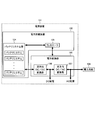
- FIG. 10 shows a schematic configuration example of a power supply device including the battery system according to the second embodiment of the present invention.
- a power supply apparatus 101 shown in FIG. 10 includes a power storage apparatus 102 and a power conversion unit 103.
- the power storage device 102 includes a battery system group 104 having a plurality of battery systems (hereinafter abbreviated as “battery systems”) according to the second embodiment of the present invention, and a controller 105.
- the power conversion unit 103 includes a bidirectional DC / DC conversion unit 106 and a bidirectional DC / AC conversion unit 107.
- the controller 105 controls the power conversion unit 103 and the battery system group 104.
- the bidirectional DC / DC conversion unit 106 converts the DC power output from the battery system group 104 by the discharge of the battery system group 104 into DC power having different voltage values, and both To the DC / AC converter 107.
- the DC power output from the bidirectional DC / DC converter 106 is also used for DC power feeding to a DC electronic device (not shown).
- the bidirectional DC / AC conversion unit 107 converts the DC power output from the bidirectional DC / DC conversion unit 106 into AC power and outputs the AC power to the external power system 108.
- the AC power output from the bidirectional DC / AC converter 107 is also used for AC power feeding to an AC electronic device (not shown).
- the DC electronic device (not shown) and the AC electronic device (not shown) correspond to the load 2A in FIGS.
- the bidirectional DC / AC conversion unit 107 converts AC power supplied from the external power system 108 into DC power and outputs the DC power to the bidirectional DC / DC conversion unit 106.
- the bidirectional DC / DC converter 106 converts the DC power supplied from the bidirectional DC / AC converter 107 into DC power having different voltage values, and outputs the DC power to the battery system group 104. Charge.
- the power system 108 corresponds to the power source 2B in FIGS.
- FIG. 11 shows a schematic configuration example of a vehicle equipped with a battery system.
- the same parts as those in FIG. 10 are denoted by the same reference numerals.
- a vehicle 109 shown in FIG. 11 is an electric vehicle, and includes a power storage device 102, a power conversion unit 103, a motor 110, and a generator 111.
- the power storage device 102 includes a battery system group 104 having a plurality of battery systems and a controller 105.
- the power conversion unit 103 includes a bidirectional DC / DC conversion unit 106 and a bidirectional DC / AC conversion unit 107.
- the motor 110 is a traveling motor that causes the vehicle 109 to travel
- the generator 111 is a generator that generates power using energy when the vehicle 109 is regeneratively braked.
- the bidirectional DC / DC converter 106 converts the DC power output from the battery system group 104 by the discharge of the battery system group 104 into DC power having different voltage values. And output to the bidirectional DC / AC conversion unit 107.
- the bidirectional DC / AC converter 107 converts the DC power output from the bidirectional DC / DC converter 106 into AC power and supplies the AC power to the motor 110.
- the motor 10 corresponds to the load 2A in FIGS.
- the bidirectional DC / AC conversion unit 107 converts the AC power supplied from the generator 111 into DC power, thereby generating bidirectional DC / DC.
- the data is output to the conversion unit 106.
- the bidirectional DC / DC converter 106 converts the DC power supplied from the bidirectional DC / AC converter 107 into DC power having different voltage values, and outputs the DC power to the battery system group 104. Charge.
- the generator 111 corresponds to the power source 2B in FIGS.
- the battery system group 104 and the bidirectional DC / AC converter 107 are directly connected without passing through the bidirectional DC / DC converter 106. Configuration is also conceivable.
- the vehicle 109 including the battery system unlike the configuration illustrated in FIG. 11, the battery system group 104 and the bidirectional DC / AC conversion unit 107 are directly connected without passing through the bidirectional DC / DC conversion unit 106. Configuration is also conceivable.
- the controller 105 may have the same function instead of the overall control unit (see FIG. 6) in each battery system of the battery system group 104.
- the overall control unit controls the power conversion unit 103.
- the equalization unit 13 having (N + ⁇ ) discharge circuits is used, but instead of this, (N + ⁇ ) pieces of (N + ⁇ ) pieces corresponding to (N + ⁇ ) pieces of batteries 11 are used.
- the deterioration determination process of step S5 the deterioration detection battery is charged using the charge circuit corresponding to the deterioration detection battery in the equalization section 13, and the deterioration detection battery by the charge is used.
- the degree of deterioration of the deterioration detecting battery may be determined from the rate of change of the state of charge.
- the parameter associated with each battery is the number of times the battery is connected in series, but the content of the parameter may be other than this.
- connection time, the number of charge / discharge cycles during connection, and the like may be used as the parameters.
- the parameter associated with each module 1 is the difference between the maximum SOC value SOCmax of the battery 11 in the module and the minimum SOC value SOCmin of the battery 11 in the module.
- the content of the parameter may be other than this.
- the number of connections, the number of charge / discharge cycles during connection, and the like may be used as the parameters.
- the charge states of the N batteries connected to the load 2A or the power source 2B may be equalized by the equalization unit 13.
- the predetermined allowable range is set in the charge state of the M modules connected in series to each other and connected to the load 2A or the power source 2B.
- the charging state of the M modules connected in series to each other and connected to the load 2A or the power source 2B may be equalized by the equalizing unit 13.
- the abnormality detection battery is determined in the same procedure as in the first embodiment, but the determination method and timing may be other than this.
- the battery 11 has a cell group in which a plurality of battery cells 11a are connected in parallel. May have a single battery cell 11a. Further, the battery 11 may include a configuration other than the battery cell.
- a general module as shown in FIG. 12B may be used instead of the module 1.
- the battery discharge stop timing is controlled by the battery discharge time, but the battery discharge stop timing is controlled by other general control. It may be controlled.
- the target SOC of the battery is set, the SOC of the battery is calculated at any time during the discharge of the battery, and the time when the target SOC is reached is set as the battery discharge stop timing.
- the SOC is used as an indicator of the state of charge of the battery or module.
- the present invention is not limited to this, and the voltage of the battery or module, the depth of discharge (Depth of discharge). : DOD), storage amount [Ah], etc. may be used as an indicator of the state of charge of the battery or module.
Landscapes
- Engineering & Computer Science (AREA)
- Power Engineering (AREA)
- Life Sciences & Earth Sciences (AREA)
- Sustainable Development (AREA)
- Sustainable Energy (AREA)
- Transportation (AREA)
- Mechanical Engineering (AREA)
- Manufacturing & Machinery (AREA)
- Chemical & Material Sciences (AREA)
- Chemical Kinetics & Catalysis (AREA)
- Electrochemistry (AREA)
- General Chemical & Material Sciences (AREA)
- Charge And Discharge Circuits For Batteries Or The Like (AREA)
- Secondary Cells (AREA)
Abstract
バッテリを(N+α)個備え、迂回スイッチを(N+α)個備え、前記バッテリそれぞれに関連付けられるパラメータ同士を比較することによりN個の前記バッテリを選択するとともに、前記迂回スイッチそれぞれを制御することにより前記N個の前記バッテリを直列接続し、α個の前記バッテリを前記N個の前記バッテリが直列接続された直列回路から切り離すモジュール制御部を備えるバッテリモジュール。なお、前記バッテリは、複数のバッテリセルが並列接続されたセル群、または、単一のバッテリセルを有している。
Description
本発明は、バッテリモジュール、バッテリシステム、バッテリシステムを備える電源装置、及びバッテリシステムを備える移動体に関する。
従来より、複数のバッテリセルが並列接続されたセル群または単一バッテリセルを有するバッテリを直列接続している構成のバッテリモジュールや複数のバッテリモジュールが直列接続されている構成のバッテリシステムが開発されている。
バッテリが直列接続されている構成のバッテリモジュールは、バッテリのうち1個でも異常があるとバッテリモジュールの充放電特性に異常が生じるという問題を有している。同様に、複数のバッテリモジュールが直列接続されている構成のバッテリシステムは、バッテリモジュールのうち1個でも異常があるとバッテリシステムの充放電特性に異常が生じるという問題を有している。
上記の問題を解決することができ長寿命化を図ることができる組電池(バッテリモジュール)が特許文献1に開示されている。特許文献1で開示されている組電池では、組電池を構成する各セルが直列接続されており、定常的な異常が検出された異常セルを組電池から切り離し、切り離した異常セルの代わりに予備電池を組電池に接続している。
特許文献1で開示されている組電池では、異常セルの代わりに予備電池を用いるので、異常セルの個数が予備電池の個数を上回った時点で組電池の寿命となり、組電池を構成する各セルの使用時間に比べて予備電池の使用時間が極端に短くなる。このように、特許文献1で開示されている組電池は、予備電池を十分に活用することができる構成ではないため、長寿命化が不十分であった。
本発明は、上記の状況に鑑み、より一層長寿命化を図ることができるバッテリモジュール、より一層長寿命化を図ることができるバッテリシステム、当該バッテリシステムを備える電源装置、及び当該バッテリシステムを備える移動体を提供することを目的とする。
上記目的を達成するために本発明に係るバッテリモジュールは、バッテリを(N+α)個備え、迂回スイッチを(N+α)個備え、前記バッテリそれぞれに関連付けられるパラメータ同士を比較することによりN個の前記バッテリを選択するとともに、前記迂回スイッチそれぞれを制御することにより前記N個の前記バッテリを直列接続し、α個の前記バッテリを前記N個の前記バッテリが直列接続された直列回路から切り離す制御部を備え、前記バッテリは、複数のバッテリセルを並列接続したセル群、または、単一のバッテリセルを有する構成とする。
上記目的を達成するために本発明に係るバッテリシステムは、バッテリモジュールを(M+β)個備え、迂回スイッチを(M+β)個備え、前記バッテリモジュールそれぞれに関連付けられるパラメータ同士を比較することによりM個の前記バッテリモジュールを選択するとともに、前記迂回スイッチそれぞれを制御することにより前記M個の前記バッテリモジュールを直列接続し、β個の前記バッテリモジュールを前記M個の前記バッテリモジュールが直列接続された直列回路から切り離す制御部を備え、前記バッテリモジュール内では、複数のバッテリセルを並列接続したセル群が複数直列接続されている、または、単一のバッテリセルが複数直列接続されている構成とする。
上記目的を達成するために本発明に係る電源装置は、上記構成のバッテリシステムと、前記バッテリシステムと外部系統電源との間に接続された電力変換部とを備える構成とする。
上記目的を達成するために本発明に係る移動体は、上記構成のバッテリシステムと、前記バッテリシステムから出力される電力により駆動されるモータと、前記バッテリシステムと前記モータとの間に接続された電力変換部とを備える構成とする。
本発明によると、バッテリモジュール、バッテリシステム、電源装置、および移動体の寿命をより一層長くすることができる。
本発明の実施形態について図面を参照して以下に説明する。
<本発明の第1実施形態>
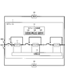
本発明の第1実施形態では、モジュール制御部14が、請求項1に記載されている「制御部」の一例に相当する。モジュール制御部14は、各バッテリ11の充電状態(state of charge:SOC)を測定する測定部14Aと、測定されたSOCから後述する劣化判定に用いるSOC変化率(ΔSOC)の計算を行う算出部14Bと、ΔSOCの値に基づいて劣化判定を行い、後述する再使用対象バッテリを選択する選択部14Cとを有している。そして、本発明の第1実施形態では、図1に示す通り、バッテリモジュール(以下、「モジュール」と略す)1が単体で、スイッチSW1を介して負荷2Aに接続され尚かつスイッチSW2を介して電源2Bに接続されて使用される。負荷2Aは、各種電子機器やモータなどの電力を消費するものであり、電源2Bは、系統電源や発電機などの電力を外部に供給するものである。モジュール1は、負荷2Aと接続されているときに放電し、電源2Bと接続されているときに充電する。したがって、スイッチSW1とSW2のいずれをオンするかによって、モジュール1の充放電を切り替えることができる。
本発明の第1実施形態では、モジュール制御部14が、請求項1に記載されている「制御部」の一例に相当する。モジュール制御部14は、各バッテリ11の充電状態(state of charge:SOC)を測定する測定部14Aと、測定されたSOCから後述する劣化判定に用いるSOC変化率(ΔSOC)の計算を行う算出部14Bと、ΔSOCの値に基づいて劣化判定を行い、後述する再使用対象バッテリを選択する選択部14Cとを有している。そして、本発明の第1実施形態では、図1に示す通り、バッテリモジュール(以下、「モジュール」と略す)1が単体で、スイッチSW1を介して負荷2Aに接続され尚かつスイッチSW2を介して電源2Bに接続されて使用される。負荷2Aは、各種電子機器やモータなどの電力を消費するものであり、電源2Bは、系統電源や発電機などの電力を外部に供給するものである。モジュール1は、負荷2Aと接続されているときに放電し、電源2Bと接続されているときに充電する。したがって、スイッチSW1とSW2のいずれをオンするかによって、モジュール1の充放電を切り替えることができる。
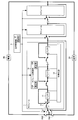
モジュール1は、図2Aに示すように複数のバッテリセル11aが並列接続されたセル群を有するバッテリ11を(N+α)個備え、迂回スイッチ12を(N+α)個備え、均等化部13と、モジュール1の全体制御を行うモジュール制御部14とをそれぞれ1個備える。なお、Nはモジュール1が単体で負荷2A又は電源2Bに接続された使用状態において負荷2Aへの電力供給又は電源2Bから供給される電力による充電に必要な定格値であり、N、αは任意の自然数である。
各迂回スイッチ12は各バッテリ11に対応しており、端子cと対応するバッテリ11の一端に繋がっている端子aとを接続することにより対応するバッテリ11を負荷2A又は電源2Bに接続するか、端子cと迂回経路を経由して対応するバッテリ11の他端に繋がっている端子bとを接続することにより対応するバッテリ11を負荷2A及び電源2Bから切り離すかを、モジュール制御部14の制御に応じて選択する。そして、(N+α)個のバッテリ11のうち、対応する迂回スイッチ12が端子cと端子aとの接続を選択しているバッテリは互いに直列接続されて負荷2A又は電源2Bに接続される。
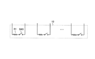
均等化部13は(N+α)個の放電回路(図1において不図示)を有している。均等化部13の各放電回路は各バッテリ11に対応しており、各バッテリ11に対して並列に接続されている。ここで、均等化部13の一構成例を図2Bに示す。図2Bに示す構成では、均等化部13の各放電回路が互いに直列接続されている抵抗R1とスイッチSW3とを有する構成であり、各放電回路はスイッチSW3がON状態のときに対応するバッテリ11を放電させる。図2Bに示す構成では、各バッテリ11の充電状態が揃うように各放電回路による各バッテリ11の放電量を調整することで、各バッテリ11のSOCを均等化することができる。
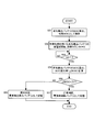
次に、モジュール1の動作について図3~図5を参照して説明する。
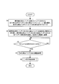
モジュール制御部14は、図3に示す動作フローを開始すると、まず始めにモジュール1が充放電を行っていないタイミングで、各バッテリ11に関連付けられるパラメータ同士を比較することにより、異常検出済みバッテリ(後述するステップS56参照)γ個を除く全バッテリ(N+α-γ)個の中から劣化検出を行うバッテリ(以下、「劣化検出バッテリ」と略す)(α-γ)個を選択する(ステップS1)。なお、γは0以上α以下の整数である。本実施形態では、上記パラメータをバッテリが直列接続された回数とし、モジュール制御部14が、上記パラメータを記憶しており、上記パラメータの値が小さいバッテリ11から順に、直列接続されるN個のバッテリとしている。さらに、モジュール制御部14は、各劣化検出バッテリについて劣化検出許可フラグを0(不許可)に設定する(ステップS1)。次に、モジュール制御部14は、当該選択に基づいて各迂回スイッチ12を制御して、異常検出済みバッテリγ個及び劣化検出バッテリ(α-γ)個を負荷2A及び電源2Bから切り離し、異常検出済みバッテリ及び劣化検出バッテリ以外の全バッテリN個を直列接続して負荷2A又は電源2Bに接続する(ステップS2)。
このように、各バッテリ11に関連付けられるパラメータ同士を比較することにより、劣化検出バッテリが選択されるので、直列接続されるN個のバッテリが固定化されることを防ぐことができる。これにより、特許文献1に開示されている組電池に比べてより一層長寿命化を図ることができる。
なお、γがαと等しい場合には劣化検出バッテリが存在しなくなるため、後述するステップS3~S5を実行せずに直ちに図3に示す動作フローを終了するとともに、モジュールの交換を促す信号を出力してもよい。
本実施形態では、定格値がNであるので、後述するステップS43やステップS44の処理を実行したときに、例えばN個より多い(N+α-γ)個のバッテリ11が負荷2Aに接続され、(N+α-γ)個のバッテリ11の電圧が負荷2Aの定格電圧を上回って負荷2Aが破損するおそれがある。このような破損を未然に防止するために、モジュール制御部14は、ステップS2の終了後にステップS3を実行する。ステップS3において、モジュール制御部14は、モジュール全体のSOCすなわち異常検出済みバッテリγ個を除く全バッテリ(N+α-γ)個の平均SOCが80%より小さいか否かを判定する。モジュール全体のSOCが80%より小さければ(ステップS3のYES)、モジュール1が充放電を行っているタイミングで、劣化検出バッテリSOC調整処理(ステップS4)、劣化判定処理(ステップS5)を順に実行し、図3に示す動作フローを終了する。なお、ステップS3での80%は例示であり、モジュール1及び負荷2Aの各仕様に応じて適切な値を設定するとよい。
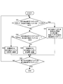
ステップS4の劣化検出バッテリSOC調整処理は、図4に示す動作フローのようになる。モジュール制御部14は、図4に示す動作フローを開始すると、まず始めに劣化検出許可フラグが0に設定されている(α-γ)個の劣化検出バッテリそれぞれについて第1の充電状態か否かを判定する(ステップS41)。本実施形態では、「第1の充電状態」として、バッテリのSOCが45%より大きく且つ55%より小さい状態を例に挙げて説明するが、「第1の充電状態」は、満充電状態に近すぎず、完全放電状態にも近すぎ無ければ、バッテリのSOCが45%より大きく且つ55%より小さい状態以外であってもよい。
モジュール制御部14は、ステップS41で否と判定された劣化検出バッテリそれぞれについてSOCが55%以上であるか否かを判定する(ステップS42)。次に、モジュール制御部14は、ステップS42で否と判定されなかった劣化検出バッテリをモジュール1が放電を行っている期間のみ負荷2Aに接続する(ステップS43)。あるいは、モジュール制御部14は、ステップS42で否と判定された劣化検出バッテリをモジュール1が充電を行っている期間のみ電源2Bに接続する(ステップS44)。
また、モジュール制御部14は、ステップS41で否と判定されなかった劣化検出バッテリをモジュール1が放電を行っている期間であってもモジュール1が充電を行っている期間であっても負荷2A及び電源2Bから切り離した状態のままにし、当該バッテリの劣化検出許可フラグを1(許可)に設定する(ステップS45)。
ステップS43、ステップS44、ステップS45の処理後、モジュール制御部14は、全ての劣化検出バッテリの劣化検出フラグが1になっているか否かを判定する(ステップS46)。全ての劣化検出バッテリの劣化検出フラグが1になっていなければ(ステップS46のNO)、ステップS41に戻る。一方、全ての劣化検出バッテリの劣化検出フラグが1になっていれば(ステップS46のYES)、図4に示す動作フローを終了する。図4に示す動作フローが終了した時点で、(α-γ)個全ての劣化検出バッテリのSOCが45%より大きく且つ55%より小さい範囲に収まっていることになる。
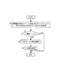
ステップS5の劣化判定処理は、図5に示す動作フローのようになる。モジュール制御部14は、各劣化検出バッテリに対して図5に示す動作フローの処理を並列に実行する。モジュール制御部14は、図5に示す動作フローを開始すると、まず始めに劣化検出バッテリのSOCを算出し、その算出結果を初期SOCとして保存する(ステップS51)。
ステップS51に続くステップS52において、モジュール制御部14は、劣化検出バッテリの放電を開始するとともに、計時カウンタtを0に設定してから計時カウンタtによる計時を開始する。劣化検出バッテリの放電は、均等化部13内の劣化検出バッテリに対応する放電回路を用いて実行される。
ステップS52に続くステップS53において、モジュール制御部14は、計時カウンタtが所定時間T(例えば24時間)以上になったか否かを判定する。そして、計時カウンタtが所定時間T以上になると(ステップS53のYES)、モジュール制御部14は、再度劣化検出バッテリのSOCを算出し、その算出結果を所定時間経過後SOCとする。また、モジュール制御部14内の算出部14Bは、初期SOC及び所定時間経過後SOCからSOC変化率(ΔSOC)を計算する(ステップS54)。なお、ΔSOCは、初期SOCから所定時間経過後SOCを引いたものを、所定時間経過後SOCを算出した時点の計時カウンタtで除算することで得られる。
ステップS54に続くステップS55において、モジュール制御部14内の選択部14Cは、ΔSOCが閾値D(Dは正の定数)より小さいか否かを判定する。ΔSOCが閾値Dより小さくなければ(ステップS55のNO)、例えば、バッテリセル内の正極と負極との間の微短絡のおそれなどがあるため、異常であると判定し、異常検出済みバッテリとして記憶し(ステップS56)、図5の動作フローを終了する。これに対して、ΔSOCが閾値Dより小さければ(ステップS55のYES)、正常であると判定し、再使用対象バッテリとして記憶し(ステップS57)、図5の動作フローを終了する。すなわち、選択部14Cはバッテリそれぞれの劣化度を評価する評価部として機能している。そして、選択部14Cにより、新たにγ1個の異常検出済みバッテリが検出され、合計γ’(=γ+γ1)個の異常検出済みバッテリを除く(α-γ’)個の再使用対象バッテリが選択される。これにより、図3の動作フローも終了する。
図3に示す動作フローを終了後、所定の期間が経過すると、再度図3に示す動作フローが開始される。ここで、再度の図3に示す動作フローでのステップS1を実行する前に、現状の互いに直列接続されて負荷2A又は電源2Bに接続されているN個のバッテリのSOCの平均値と、現状の(α-γ’)個の再使用対象バッテリのSOCの平均値との差が所定値より小さいか否かを判定する。当該判定の結果が否でないとき、再度の図3に示す動作フローでのステップS1を実行する。上述の通り、本実施形態では、上記パラメータをバッテリが直列接続された回数とし、モジュール制御部14が、上記パラメータを記憶しており、上記パラメータの値が小さいバッテリ11から順に、直列接続されるN個のバッテリとしているので、図3に示す動作フローを実行する毎に、劣化検出バッテリとして選択するバッテリが順次異なり、劣化検出バッテリがローテーションする。当該ローテーションにより、劣化検出を満遍なく行うことができるとともに、異常検出済みバッテリを除く全バッテリの使用時間(負荷2A又は電源2Bに接続され充放電を行っている期間)のバッテリ間でのばらつきを低減することができる。また、本実施形態では、モジュール1が負荷2A又は電源2Bに接続された状態で充放電を停止することなく、劣化判定を行うことができ、次のローテーションの準備を滞りなく行うことができる。また、本実施形態では、直列接続されたN個のバッテリのSOCの平均値と(α-γ’)個の再使用対象バッテリのSOCの平均値との差が所定値より小さい場合に、図3に示す動作フローを繰り返すようにしている。これにより、再度の図3に示す動作フローでのステップS1を実行した後で、新たに直列接続されるN個のバッテリのSOCが大きくばらつくことを防止することができる。
本実施形態では、モジュール内の各バッテリのSOCを均等化するために一般的に設けられている均等化部を利用してバッテリの劣化判定を行っているので、バッテリの劣化判定を行うための特別な回路を設ける必要がなく、バッテリの劣化判定を低コストで実現することができる。また、本実施形態では、バッテリの劣化判定を行うための下準備を行うための特別な回路を設けずに、負荷2A及び電源2Bを利用してバッテリの劣化判定を行うための下準備(図4のステップS43及びS44の処理)を行っているので、バッテリの劣化判定を行うための下準備を低コストで実現することができる。また、本実施形態では、負荷2A及び電源2Bから切り離したバッテリを劣化判定の対象としているので、充放電中の測定値の解析による劣化判定に比べて高精度にバッテリの劣化度を判定でき、微細な異常(劣化)を検出することができる。
<本発明の第2実施形態>
本発明の第2実施形態では、全体制御部4及びモジュール制御部14が、請求項4に記載されている「制御部」の一例に相当する。全体制御部4は、後述する均等化対象バッテリを選択する選択部4Aを有している。また、モジュール制御部14は、各バッテリ11のSOCを測定する測定部14Aと、測定されたSOCからモジュール1内のバッテリ11のSOCの最大値SOCmax及び最小値SOCminの差を算出する算出部14Bとを有する。そして、本発明の第2実施形態では、(M+β)個のモジュール1と、(M+β)個の迂回スイッチ3と、1個の全体制御部4とを備えるバッテリシステムがスイッチSW1を介して負荷2Aに接続され尚かつスイッチSW2を介して電源2Bに接続されて使用される(図6参照)。本発明の第2実施形態に係るバッテリシステムは、負荷2Aと接続されているときに放電し、電源2Bと接続されているときに充電する。したがって、スイッチSW1とSW2のいずれをオンするかによって、本発明の第2実施形態に係るバッテリシステムの充放電を切り替えることができる。なお、図6において図1と同一の部分には同一の符号を付し詳細な説明を省略する。また、Mは負荷2Aへの電力供給又は電源2Bから供給される電力による充電に必要な定格値であり、M、βは任意の自然数である。
本発明の第2実施形態では、全体制御部4及びモジュール制御部14が、請求項4に記載されている「制御部」の一例に相当する。全体制御部4は、後述する均等化対象バッテリを選択する選択部4Aを有している。また、モジュール制御部14は、各バッテリ11のSOCを測定する測定部14Aと、測定されたSOCからモジュール1内のバッテリ11のSOCの最大値SOCmax及び最小値SOCminの差を算出する算出部14Bとを有する。そして、本発明の第2実施形態では、(M+β)個のモジュール1と、(M+β)個の迂回スイッチ3と、1個の全体制御部4とを備えるバッテリシステムがスイッチSW1を介して負荷2Aに接続され尚かつスイッチSW2を介して電源2Bに接続されて使用される(図6参照)。本発明の第2実施形態に係るバッテリシステムは、負荷2Aと接続されているときに放電し、電源2Bと接続されているときに充電する。したがって、スイッチSW1とSW2のいずれをオンするかによって、本発明の第2実施形態に係るバッテリシステムの充放電を切り替えることができる。なお、図6において図1と同一の部分には同一の符号を付し詳細な説明を省略する。また、Mは負荷2Aへの電力供給又は電源2Bから供給される電力による充電に必要な定格値であり、M、βは任意の自然数である。
各迂回スイッチ3は各モジュール1に対応しており、端子fと対応するモジュール1の一端に繋がっている端子dとを接続することにより対応するモジュール1を負荷2A又は電源2Bに接続するか、端子fと迂回経路を経由して対応するモジュール1の他端に繋がっている端子eとを接続することにより対応するモジュール1を負荷2A及び電源2Bから切り離すかを、全体制御部4の制御に応じて選択する。そして、(M+β)個のモジュール1のうち、対応する迂回スイッチ3が端子fと端子dとの接続を選択しているモジュールは互いに直列接続されて負荷2A又は電源2Bに接続される。
次に、本発明の第2実施形態に係るバッテリシステムの動作について図7~図9を参照して説明する。
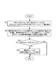
本実施形態では、各モジュール1に関連付けられるパラメータを、モジュール内のバッテリ11のSOCの最大値SOCmaxとモジュール内のバッテリ11のSOCの最小値SOCminとの差とし、全体制御部4が、モジュール1毎に上記パラメータを記憶している。全体制御部4は、図7に示す動作フローを開始すると、まず始めに異常検出済みモジュールε個を除く全モジュール(M+β-ε)個のモジュール制御部14内の測定部14Aを制御して、異常検出済みモジュールε個を除く全モジュール(M+β-ε)個について、異常検出済みバッテリγ個を除く各バッテリ11のSOCを測定させる。なお、εは0以上β以下の整数である。次に、全体制御部4は、異常検出済みモジュールε個を除く全モジュール(M+β-ε)個のモジュール制御部14内の算出部14Bに、モジュール1毎に上述したSOCmaxとSOCminとを求めさせるとともにSOCmax-SOCminを求めさせる(ステップS6)。ここで、異常検出済みモジュールとは、例えば、モジュール内に異常検出済みバッテリが1個でも存在するモジュールと定義してもよく、また例えば、モジュール内に存在する異常検出済みバッテリがζ個であるモジュールと定義してもよい。なお、ζは2以上の任意の自然数である。また、異常検出済みバッテリは、本発明の第1実施形態と同様の手順で判定される。
ステップS6に続くステップS7において、全体制御部4は、負荷2A又は電源2Bを流れる電流の絶対値が所定の微小値δ(δは正の定数)より小さいか否かを判定する。負荷2A又は電源2Bを流れる電流の絶対値が所定の微小値δより小さければ(ステップS7のYES)、モジュール入替え処理(ステップS8)、均等化処理(ステップS9)を順に実行し、図7に示す動作フローを終了する。これに対して、負荷2A又は電源2Bを流れる電流の絶対値が所定の微小値δより小さくなければ(ステップS7のNO)、モジュール入替え処理(ステップS8)及び均等化処理(ステップS9)を実行せずに、図7に示す動作フローを終了する。
ステップS8のモジュール入替え処理は、図8に示す動作フローのようになる。全体制御部4内の選択部4Aは、図8に示す動作フローを開始すると、まず始めに異常検出済みモジュールε個を除く全モジュール(M+β-ε)個を対象として、各モジュール1に関連付けられるパラメータ同士を比較することにより、第2の充電状態であるモジュールの中から、算出部14Bにより算出されたSOCmax-SOCminが大きい順に(β-ε)個を選択する(ステップS81)。本実施形態では、「第2の充電状態」として、SOCmaxが50%より大きく且つ60%より小さい状態を例に挙げて説明するが、「第2の充電状態」は、SOCmaxが50%より大きく且つ60%より小さい状態以外であってもよい。以下、当該選択によって選択されたモジュールを「選択モジュール」と称す。
ステップS81に続くステップS82において、全体制御部4は、当該選択に基づいて各迂回スイッチ3を制御して、異常検出済みモジュールε個及び選択モジュール(β-ε)個を負荷2A及び電源2Bから切り離し、異常検出済みモジュール及び選択モジュール以外の全モジュールM個を直列接続して負荷2又は電源2Bに接続する。
このように、各モジュール1に関連付けられるパラメータ同士を比較することにより、選択モジュールが選ばれるので、直列接続されるM個のモジュールが固定化されることを防ぐことができる。これにより、より一層長寿命化を図ることができる。
なお、異常検出済みモジュールε個を除く全モジュール(M+β-ε)個の中に、第2の充電状態であるモジュールが(β-ε)個未満しかない場合には、異常検出済みモジュール及び選択モジュール以外の全モジュールの中から(β-ε)個に対して不足する個数だけ任意に選択して負荷2A及び電源2Bから切り離す。これにより、ステップS81の処理終了後に、M個のモジュールが直列接続されて負荷2A又は電源2Bに接続され、β個のモジュールが負荷2及び電源2Bから切り離された状態になるようにする。また、εがβと等しい場合には選択モジュールが存在しなくなるため、後述するステップS83~S84を実行せずに直ちに図8に示す動作フローを終了するとともに、モジュールの交換を促す信号を出力してもよい。
ステップS82に続くステップS83において、全体制御部4は、選択モジュールそれぞれについて、SOCmax-SOCminが所定値Δ(Δは正の定数)より大きいか否かを判定する。ステップS83で否と判定されなかった選択モジュールを均等化対象モジュールと決定し(ステップS84)、ステップS83で否と判定された選択モジュールを均等化対象モジュールとせずに、図8に示す動作フローを終了する。
ステップS9の均等化処理は、図9に示す動作フローのようになる。なお、全体制御部4は、各均等化対象モジュールに対して後述するステップS92~S95の処理を並列に実行する。
全体制御部4は、図9に示す動作フローを開始すると、まず始めに均等化対象モジュールが有るか否かを判定する(ステップS91)。均等化対象モジュールがなければ(ステップS91のNO)、直ちに図9に示す動作フローを終了する。一方、均等化対象モジュールが少なくとも1つ有れば(ステップS91のYES)、ステップS92に移行する。
ステップS92において、全体制御部4は、均等化対象モジュールのモジュール制御部14を制御して、均等化対象モジュール内の異常検出済みバッテリγ個を除く各バッテリのSOCを揃えるための各バッテリの放電時間T[i]を計算させる。放電時間T[i]の計算は、例えば、放電後の目標となるSOCと現在のSOCとの差にバッテリの満充電容量を乗じた値(Ah)と、放電回路の抵抗値とバッテリの電圧から求まる放電電流(A)とを用いて求められる。
ステップS92に続くステップS93において、T[i]が0より大きいバッテリに対して放電を開始する。この放電は、均等化部13内のこのバッテリに対応する放電回路を用いて実行される。
ステップS93に続くステップS94において、全体制御部4は、均等化対象モジュールのモジュール制御部14を制御して、計時カウンタtを0に初期化させてから、計時カウンタtによる計時を開始させる。
ステップS94に続くステップS95において、全体制御部4は、均等化対象モジュールのモジュール制御部14を制御して、T[i]が計時カウンタt以下になったバッテリの放電を停止させる。
ステップS95に続くステップS96において、全体制御部4は、均等化対象モジュールのモジュール制御部14を制御して、ステップS93において放電を開始した全バッテリの放電が終了したか否かを判定させる。ステップS93において放電を開始した全バッテリの放電が終了していなければ(ステップS96のNO)、計時カウンタtをインクリメントするとともに放電を継続し(ステップS97)、ステップS95に戻る。一方、ステップS93において放電を開始した全バッテリの放電が終了していれば(ステップS96のYES)、計時カウンタtによる計時を終了して、図9に示す動作フローを終了する。図9に示す動作フローが終了した時点で、均等化対象モジュール内のバッテリについては均等化処理が終了しており、負荷2A及び電源2Bから切り離されている(β-ε)個の選択モジュールに含まれ得る均等化対象モジュールの均等化処理も終了していることになる。これにより、図7の動作フローも終了する。
図7に示す動作フローを終了後、所定の期間が経過すると、再度図7に示す動作フローが開始され、直列接続されるM個のモジュールが新たに選択される。本実施形態では、均等化対象モジュールが負荷2A及び電源2Bから切り離されているので、バッテリシステムが充放電中であっても、均等化処理における均等化対象モジュールの放電を実行することができる。これにより、バッテリシステムの充放電に関する制約が低減されるので、利便性が向上する。すなわち、本実施形態では、異常検出済みモジュールε個及び選択モジュール(β-ε)個を除いたM個のモジュールが負荷2A又は電源2Bに接続された状態で充放電を停止することなく、選択モジュールのうち特定の充電状態であるモジュール(均等化対象モジュール)に対して均等化処理を行うことができ、次のモジュール選択(直列接続されるM個のモジュールの選択)の準備を滞りなく行える。また、本実施形態では、図7に示す動作フローを実行する毎に、順次異なるモジュールを選択して均等化処理を行いながら、モジュールをローテーションして直列接続する。当該ローテーションにより、直列接続されたM個のモジュール間のSOCのばらつきを低減することができる。
本発明の第2実施形態に係るバッテリシステムは、例えば電源装置に用いられる。本発明の第2実施形態に係るバッテリシステムを備える電源装置の概略構成例を図10に示す。
図10に示す電源装置101は、電力貯蔵装置102と、電力変換部103とを備えている。電力貯蔵装置102は、本発明の第2実施形態に係るバッテリシステム(以下、「バッテリシステム」と略す)を複数有するバッテリシステム群104と、コントローラ105とを備えている。電力変換部103は、双方向DC/DC変換部106と、双方向DC/AC変換部107とを備えている。コントローラ105は、電力変換部103と、バッテリシステム群104とを制御する。
電源装置101の放電動作モードにおいて、双方向DC/DC変換部106は、バッテリシステム群104の放電によりバッテリシステム群104から出力されるDC電力を、異なる電圧値のDC電力に変換して、双方向DC/AC変換部107に出力する。双方向DC/DC変換部106から出力されるDC電力はDC電子機器(不図示)へのDC給電にも用いられる。双方向DC/AC変換部107は、双方向DC/DC変換部106から出力されるDC電力を、AC電力に変換して、外部の電力系統108に出力する。双方向DC/AC変換部107から出力されるAC電力はAC電子機器(不図示)へのAC給電にも用いられる。DC電子機器(不図示)やAC電子機器(不図示)は図1及び図6中の負荷2Aに相当するものである。
電源装置101の充電動作モードにおいて、双方向DC/AC変換部107は、外部の電力系統108から供給されるAC電力を、DC電力に変換して、双方向DC/DC変換部106に出力する。双方向DC/DC変換部106は、双方向DC/AC変換部107から供給されるDC電力を、異なる電圧値のDC電力に変換して、バッテリシステム群104に出力し、バッテリシステム群104を充電する。電力系統108は図1及び図6中の電源2Bに相当するものである。
また、バッテリシステムは、移動体(例えば、車両など)に搭載されてもよい。バッテリシステムを搭載する車両の概略構成例を図11に示す。なお、図11において図10と同一の部分には同一の符号を付す。
図11に示す車両109は、電気自動車であって、電力貯蔵装置102と、電力変換部103と、モータ110と、発電機111とを備えている。電力貯蔵装置102は、バッテリシステムを複数有するバッテリシステム群104と、コントローラ105とを備えている。電力変換部103は、双方向DC/DC変換部106と、双方向DC/AC変換部107とを備えている。モータ110は車両109を走行させる走行用モータであり、発電機111は車両109を回生制動する時のエネルギーを利用して発電を行う発電機である。
モータ110の駆動により車両109が走行しているときにおいて、双方向DC/DC変換部106は、バッテリシステム群104の放電によりバッテリシステム群104から出力されるDC電力を、異なる電圧値のDC電力に変換して、双方向DC/AC変換部107に出力する。双方向DC/AC変換部107は、双方向DC/DC変換部106から出力されるDC電力を、AC電力に変換して、モータ110に供給する。モータ10は図1及び図6中の負荷2Aに相当するものである。
車両109の回生制動により発電機111が発電しているときにおいて、双方向DC/AC変換部107は、発電機111から供給されるAC電力を、DC電力に変換して、双方向DC/DC変換部106に出力する。双方向DC/DC変換部106は、双方向DC/AC変換部107から供給されるDC電力を、異なる電圧値のDC電力に変換して、バッテリシステム群104に出力し、バッテリシステム群104を充電する。発電機111は図1及び図6中の電源2Bに相当するものである。
また、バッテリシステムを備える電源装置101において、図10に示す構成と異なり、バッテリシステム群104と双方向DC/AC変換部107とが双方向DC/DC変換部106を介さずに直接接続される構成も考えられる。同様に、バッテリシステムを備える車両109において、図11に示す構成と異なり、バッテリシステム群104と双方向DC/AC変換部107とが双方向DC/DC変換部106を介さずに直接接続される構成も考えられる。また、電源装置101及び車両109において、バッテリシステム群104の各バッテリシステム内の全体制御部(図6参照)に代えて、コントローラ105が同様の機能を備えていてもよい。あるいは、電源装置101及び車両109において、電力貯蔵装置102に代えて、本発明の第2実施形態に係るバッテリシステムを用いる構成も考えられる。この場合には、全体制御部(図6参照)が電力変換部103を制御する。
<変形例等>
以上、本発明に係る実施形態について説明したが、本発明の範囲はこれに限定されるものではなく、発明の主旨を逸脱しない範囲で種々の変更を加えて実行することができる。
以上、本発明に係る実施形態について説明したが、本発明の範囲はこれに限定されるものではなく、発明の主旨を逸脱しない範囲で種々の変更を加えて実行することができる。
例えば、上述した第1実施形態では、(N+α)個の放電回路を有する均等化部13を用いたが、これの代わりに、(N+α)個のバッテリ11に1対1対応する(N+α)個の充電回路を有する均等化部を用い、ステップS5の劣化判定処理において、均等化部13内の劣化検出バッテリに対応する充電回路を用いた劣化検出バッテリの充電を行い、その充電による劣化検出バッテリの充電状態の変化率から劣化検出バッテリの劣化度を判定するようにしてもよい。
また、例えば、上述した第1実施形態では、各バッテリに関連付けられるパラメータを、バッテリが直列接続された回数としたが、パラメータの内容はこれ以外であっても構わない。例えば、接続時間、接続中の充放電サイクル数等を上記パラメータとして用いても良い。
また、例えば、上述した第2実施形態では、各モジュール1に関連付けられるパラメータを、モジュール内のバッテリ11のSOCの最大値SOCmaxとモジュール内のバッテリ11のSOCの最小値SOCminとの差としたが、パラメータの内容はこれ以外であっても構わない。例えば、接続回数、接続中の充放電サイクル数等を上記パラメータとして用いても良い。
また、例えば、上述した第1実施形態において、互いに直列接続されて負荷2A又は電源2Bに接続されているN個のバッテリの充電状態に所定の許容範囲を越えるばらつきがあるときに、互いに直列接続されて負荷2A又は電源2Bに接続されているN個のバッテリの充電状態を均等化部13により均等化するようにしてもよい。
また、例えば、上述した第2実施形態において、ステップS8のモジュール入替え処理を実行した結果、互いに直列接続されて負荷2A又は電源2Bに接続されているM個のモジュールの充電状態に所定の許容範囲を越えるばらつきがあるときに、互いに直列接続されて負荷2A又は電源2Bに接続されているM個のモジュールの充電状態を均等化部13により均等化するようにしてもよい。
また、例えば、上述した第2実施形態において、異常検出バッテリが第1実施形態と同様の手順で判定されていたが、判定の方法及びタイミングはこれ以外であっても構わない。
また、例えば、上述した第1実施形態及び第2実施形態では、バッテリ11は、複数のバッテリセル11aが並列接続されたセル群を有していたが、これに限らず、図12Aに示すように単一のバッテリセル11aを有していてもよい。また、バッテリ11はバッテリセル以外の構成を含んでいてもよい。
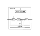
また、例えば、上述した第2実施形態において、モジュール1の代わりに、図12Bに示すような一般的なモジュールを用いるようにしてもよい。
また、例えば、上述した第2実施形態では、ステップS9の均等化処理において、バッテリの放電時間によってバッテリの放電停止タイミングが制御されているが、他の一般的な制御によりバッテリの放電停止タイミングが制御されてもよい。他の一般的な制御としては、例えば、バッテリの目標SOCを設定し、バッテリの放電中随時バッテリのSOCを計算し、目標SOCに達した時点をバッテリの放電停止タイミングとする制御がある。
また、例えば、上述した第1実施形態及び第2実施形態では、バッテリ又はモジュールの充電状態の指標としてSOCを用いているが、これに限らず、バッテリ又はモジュールの電圧、放電深度(Depth of discharge:DOD)、蓄電量[Ah]等をバッテリ又はモジュールの充電状態の指標として用いてもよい。
1 モジュール
2A 負荷
2B 電源
3 迂回スイッチ
4 全体制御部
4A 選択部
11 バッテリ
11a バッテリセル
12 迂回スイッチ
13 均等化部
14 モジュール制御部
14A 測定部
14B 算出部
14C 選択部
101 電源装置
102 電力貯蔵装置
103 電力変換部
104 バッテリシステム群
105 コントローラ
106 双方向DC/DC変換部
107 双方向DC/AC変換部
108 電力系統
109 車両
110 モータ
111 発電機
R1 抵抗
SW1~SW3 スイッチ
2A 負荷
2B 電源
3 迂回スイッチ
4 全体制御部
4A 選択部
11 バッテリ
11a バッテリセル
12 迂回スイッチ
13 均等化部
14 モジュール制御部
14A 測定部
14B 算出部
14C 選択部
101 電源装置
102 電力貯蔵装置
103 電力変換部
104 バッテリシステム群
105 コントローラ
106 双方向DC/DC変換部
107 双方向DC/AC変換部
108 電力系統
109 車両
110 モータ
111 発電機
R1 抵抗
SW1~SW3 スイッチ
Claims (8)
- バッテリを(N+α)個備え、
迂回スイッチを(N+α)個備え、
前記バッテリそれぞれに関連付けられるパラメータ同士を比較することによりN個の前記バッテリを選択するとともに、前記迂回スイッチそれぞれを制御することにより前記N個の前記バッテリを直列接続し、α個の前記バッテリを前記N個の前記バッテリが直列接続された直列回路から切り離す制御部を備え、
前記バッテリは、複数のバッテリセルを並列接続したセル群、または、単一のバッテリセルを有することを特徴とするバッテリモジュール。 - 前記パラメータは前記バッテリが直列接続された回数であり、
前記制御部は、前記パラメータの値が小さい前記バッテリから順に前記N個の前記バッテリを選択する請求項1に記載のバッテリモジュール。 - 前記制御部は、前記α個の前記バッテリから再使用対象バッテリを選択する選択部を備え、
前記制御部は、前記N個の前記バッテリの充電状態の平均値と、前記選択部により選択された前記再使用対象バッテリの充電状態の平均値との差が所定値より小さいときに、前記パラメータ同士を比較することにより新たなN個の前記バッテリを選択するとともに、前記迂回スイッチそれぞれを制御することにより前記新たなN個の前記バッテリを直列接続し、α個の前記バッテリを前記新たなN個の前記バッテリが直列接続された直列回路から切り離す請求項1または請求項2に記載のバッテリモジュール。 - バッテリモジュールを(M+β)個備え、
迂回スイッチを(M+β)個備え、
前記バッテリモジュールそれぞれに関連付けられるパラメータ同士を比較することによりM個の前記バッテリモジュールを選択するとともに、前記迂回スイッチそれぞれを制御することにより前記M個の前記バッテリモジュールを直列接続し、β個の前記バッテリモジュールを前記M個の前記バッテリモジュールが直列接続された直列回路から切り離す制御部を備え、
前記バッテリモジュール内では、複数のバッテリセルを並列接続したセル群が複数直列接続されている、または、単一のバッテリセルが複数直列接続されていることを特徴とするバッテリシステム。 - 前記制御部は、前記バッテリモジュール毎に、前記複数直列接続されている前記セル群または前記複数直列接続されている前記単一のバッテリセルのそれぞれの充電状態の最大値と最小値との差を算出する算出部を備え、
前記パラメータは前記算出部により算出された前記充電状態の最大値と最小値との差であり、
前記制御部は、前記パラメータの値が小さい前記バッテリモジュールから順に前記M個の前記バッテリモジュールを選択する請求項4に記載のバッテリシステム。 - 前記制御部は、前記β個の前記バッテリモジュールの中から均等化対象バッテリモジュールを選択する選択部と、前記均等化対象バッテリモジュール内で、前記複数直列接続されている前記セル群または前記複数直列接続されている前記単一のバッテリセルのそれぞれの充電状態を均等化する均等化部とを備え、
前記制御部は、前記選択部によって選択された前記均等化対象バッテリモジュールに対して、前記均等化部が前記充電状態の均等化を行った後、前記パラメータ同士を比較することにより新たなM個の前記バッテリモジュールを選択するとともに、前記迂回スイッチそれぞれを制御することにより前記新たなM個の前記バッテリモジュールを直列接続し、β個の前記バッテリモジュールを前記新たなM個の前記バッテリモジュールが直列接続された直列回路から切り離す請求項4又は請求項5に記載のバッテリシステム。 - 請求項4~6のいずれか1項に記載のバッテリシステムと、
前記バッテリシステムと外部系統電源との間に接続された電力変換部とを備えることを特徴とする電源装置。 - 請求項4~6のいずれか1項に記載のバッテリシステムと、
前記バッテリシステムから出力される電力により駆動されるモータと、
前記バッテリシステムと前記モータとの間に接続された電力変換部とを備えることを特徴とする移動体。
Applications Claiming Priority (2)
| Application Number | Priority Date | Filing Date | Title |
|---|---|---|---|
| JP2011-017680 | 2011-01-31 | ||
| JP2011017680 | 2011-01-31 |
Publications (1)
| Publication Number | Publication Date |
|---|---|
| WO2012105448A1 true WO2012105448A1 (ja) | 2012-08-09 |
Family
ID=46602664
Family Applications (1)
| Application Number | Title | Priority Date | Filing Date |
|---|---|---|---|
| PCT/JP2012/051831 Ceased WO2012105448A1 (ja) | 2011-01-31 | 2012-01-27 | バッテリモジュール、バッテリシステム、電源装置、及び移動体 |
Country Status (1)
| Country | Link |
|---|---|
| WO (1) | WO2012105448A1 (ja) |
Cited By (19)
| Publication number | Priority date | Publication date | Assignee | Title |
|---|---|---|---|---|
| CN103647316A (zh) * | 2013-12-03 | 2014-03-19 | 深圳市雅格朗电子有限公司 | 一种串联锂电池组电源均衡管理系统 |
| WO2014122832A1 (ja) * | 2013-02-06 | 2014-08-14 | 日本電気株式会社 | 蓄電装置及び劣化判定方法 |
| JP2014180091A (ja) * | 2013-03-14 | 2014-09-25 | Npo Hiroshima Junkangata Shakai Suishin Kiko | 二次電池リコンディション装置 |
| EP3069919A1 (en) * | 2015-03-16 | 2016-09-21 | Thunder Power Hong Kong Ltd. | Battery pack and connecting circuits of battery modules |
| CN107171382A (zh) * | 2017-05-19 | 2017-09-15 | 宁德时代新能源科技股份有限公司 | 电池组充电系统和方法 |
| US9954260B2 (en) | 2015-03-16 | 2018-04-24 | Thunder Power New Energy Vehicle Development Company Limited | Battery system with heat exchange device |
| US10173687B2 (en) | 2015-03-16 | 2019-01-08 | Wellen Sham | Method for recognizing vehicle driver and determining whether driver can start vehicle |
| CN109216797A (zh) * | 2017-06-29 | 2019-01-15 | 青岛恒金源电子科技有限公司 | 一种锂离子电池组的运行方法 |
| US10384533B2 (en) | 2015-03-16 | 2019-08-20 | Thunder Power New Energy Vehicle Development Company Limited | Fastening method for components |
| US10450007B2 (en) | 2015-03-16 | 2019-10-22 | Thunder Power New Energy Vehicle Development Company Limited | Underbody manufacturing method and vehicle underbody |
| US10500919B2 (en) | 2015-03-16 | 2019-12-10 | Thunder Power New Energy Vehicle Development Company Limited | Fastening method for components |
| US10703211B2 (en) | 2015-03-16 | 2020-07-07 | Thunder Power New Energy Vehicle Development Company Limited | Battery pack, battery charging station, and charging method |
| EP3793057A1 (en) * | 2019-09-10 | 2021-03-17 | Yazaki Corporation | Battery control unit and battery system |
| EP3859936A1 (en) * | 2020-01-28 | 2021-08-04 | Yazaki Corporation | Battery control unit and battery system |
| EP3912843A1 (en) * | 2020-05-20 | 2021-11-24 | Ningbo Geely Automobile Research & Development Co., Ltd. | A vehicle power supply system |
| CN114759622A (zh) * | 2020-12-25 | 2022-07-15 | 比亚迪股份有限公司 | 电池系统、车辆及其控制方法 |
| CN115036951A (zh) * | 2021-03-04 | 2022-09-09 | 华为数字能源技术有限公司 | 储能系统及电池管理方法 |
| CN116198387A (zh) * | 2023-03-29 | 2023-06-02 | 博雷顿科技股份公司 | 一种电池不一致性控制方法及系统 |
| CN116632959A (zh) * | 2023-04-23 | 2023-08-22 | 江苏天合储能有限公司 | 一种储能系统动态均衡方法 |
Citations (5)
| Publication number | Priority date | Publication date | Assignee | Title |
|---|---|---|---|---|
| JP2001218376A (ja) * | 2000-02-03 | 2001-08-10 | Toyota Motor Corp | 組電池を構成する単電池の充電状態を制御する装置、方法、該装置を用いた電池モジュールおよび電動車両 |
| JP2002063943A (ja) * | 2000-08-22 | 2002-02-28 | Shin Kobe Electric Mach Co Ltd | 密閉型鉛蓄電池 |
| JP2007311255A (ja) * | 2006-05-19 | 2007-11-29 | Fuji Electric Systems Co Ltd | 組電池状態測定装置、組電池劣化判定方法および組電池劣化判定プログラム |
| JP2010239711A (ja) * | 2009-03-30 | 2010-10-21 | Japan Research Institute Ltd | 電池制御装置、車両、及び電池制御方法 |
| JP2010273417A (ja) * | 2009-05-20 | 2010-12-02 | Honda Motor Co Ltd | 電動車両 |
-
2012
- 2012-01-27 WO PCT/JP2012/051831 patent/WO2012105448A1/ja not_active Ceased
Patent Citations (5)
| Publication number | Priority date | Publication date | Assignee | Title |
|---|---|---|---|---|
| JP2001218376A (ja) * | 2000-02-03 | 2001-08-10 | Toyota Motor Corp | 組電池を構成する単電池の充電状態を制御する装置、方法、該装置を用いた電池モジュールおよび電動車両 |
| JP2002063943A (ja) * | 2000-08-22 | 2002-02-28 | Shin Kobe Electric Mach Co Ltd | 密閉型鉛蓄電池 |
| JP2007311255A (ja) * | 2006-05-19 | 2007-11-29 | Fuji Electric Systems Co Ltd | 組電池状態測定装置、組電池劣化判定方法および組電池劣化判定プログラム |
| JP2010239711A (ja) * | 2009-03-30 | 2010-10-21 | Japan Research Institute Ltd | 電池制御装置、車両、及び電池制御方法 |
| JP2010273417A (ja) * | 2009-05-20 | 2010-12-02 | Honda Motor Co Ltd | 電動車両 |
Cited By (26)
| Publication number | Priority date | Publication date | Assignee | Title |
|---|---|---|---|---|
| US10038325B2 (en) | 2013-02-06 | 2018-07-31 | Nec Corporation | Electric storage device and deterioration determination method |
| WO2014122832A1 (ja) * | 2013-02-06 | 2014-08-14 | 日本電気株式会社 | 蓄電装置及び劣化判定方法 |
| JP2014180091A (ja) * | 2013-03-14 | 2014-09-25 | Npo Hiroshima Junkangata Shakai Suishin Kiko | 二次電池リコンディション装置 |
| CN103647316A (zh) * | 2013-12-03 | 2014-03-19 | 深圳市雅格朗电子有限公司 | 一种串联锂电池组电源均衡管理系统 |
| US10703211B2 (en) | 2015-03-16 | 2020-07-07 | Thunder Power New Energy Vehicle Development Company Limited | Battery pack, battery charging station, and charging method |
| US9954260B2 (en) | 2015-03-16 | 2018-04-24 | Thunder Power New Energy Vehicle Development Company Limited | Battery system with heat exchange device |
| US10173687B2 (en) | 2015-03-16 | 2019-01-08 | Wellen Sham | Method for recognizing vehicle driver and determining whether driver can start vehicle |
| US10384533B2 (en) | 2015-03-16 | 2019-08-20 | Thunder Power New Energy Vehicle Development Company Limited | Fastening method for components |
| US10450007B2 (en) | 2015-03-16 | 2019-10-22 | Thunder Power New Energy Vehicle Development Company Limited | Underbody manufacturing method and vehicle underbody |
| US10500919B2 (en) | 2015-03-16 | 2019-12-10 | Thunder Power New Energy Vehicle Development Company Limited | Fastening method for components |
| EP3069919A1 (en) * | 2015-03-16 | 2016-09-21 | Thunder Power Hong Kong Ltd. | Battery pack and connecting circuits of battery modules |
| CN107171382A (zh) * | 2017-05-19 | 2017-09-15 | 宁德时代新能源科技股份有限公司 | 电池组充电系统和方法 |
| CN109216797A (zh) * | 2017-06-29 | 2019-01-15 | 青岛恒金源电子科技有限公司 | 一种锂离子电池组的运行方法 |
| EP3793057A1 (en) * | 2019-09-10 | 2021-03-17 | Yazaki Corporation | Battery control unit and battery system |
| US11469601B2 (en) | 2019-09-10 | 2022-10-11 | Yazaki Corporation | Battery control unit and battery system |
| CN113258629A (zh) * | 2020-01-28 | 2021-08-13 | 矢崎总业株式会社 | 电池控制单元和电池系统 |
| EP3859936A1 (en) * | 2020-01-28 | 2021-08-04 | Yazaki Corporation | Battery control unit and battery system |
| CN113258629B (zh) * | 2020-01-28 | 2024-02-09 | 矢崎总业株式会社 | 电池控制单元和电池系统 |
| EP3912843A1 (en) * | 2020-05-20 | 2021-11-24 | Ningbo Geely Automobile Research & Development Co., Ltd. | A vehicle power supply system |
| CN114759622A (zh) * | 2020-12-25 | 2022-07-15 | 比亚迪股份有限公司 | 电池系统、车辆及其控制方法 |
| CN114759622B (zh) * | 2020-12-25 | 2024-12-10 | 比亚迪股份有限公司 | 电池系统、车辆及其控制方法 |
| CN115036951A (zh) * | 2021-03-04 | 2022-09-09 | 华为数字能源技术有限公司 | 储能系统及电池管理方法 |
| CN115036951B (zh) * | 2021-03-04 | 2025-11-25 | 华为数字能源技术有限公司 | 储能系统及电池管理方法 |
| CN116198387A (zh) * | 2023-03-29 | 2023-06-02 | 博雷顿科技股份公司 | 一种电池不一致性控制方法及系统 |
| WO2024199183A1 (zh) * | 2023-03-29 | 2024-10-03 | 博雷顿科技股份公司 | 一种电池不一致性控制方法及系统 |
| CN116632959A (zh) * | 2023-04-23 | 2023-08-22 | 江苏天合储能有限公司 | 一种储能系统动态均衡方法 |
Similar Documents
| Publication | Publication Date | Title |
|---|---|---|
| US10559963B2 (en) | Balance correction apparatus and electric storage system | |
| US8928174B2 (en) | Battery control apparatus, battery control method, and vehicle | |
| CN102097835B (zh) | 组式电池 | |
| JP5480520B2 (ja) | 電池制御装置、車両、及び電池制御方法 | |
| CN103779620B (zh) | 蓄电系统 | |
| CN101911429B (zh) | 一种平衡高压电池组的方法 | |
| JP5621818B2 (ja) | 蓄電システムおよび均等化方法 | |
| CN104204832B (zh) | 用于互连电池组中的电池组电池的方法、电池组和监控装置 | |
| CN112384405B (zh) | 控制车辆中的电池系统的方法 | |
| CN103180749B (zh) | 一种用于检验电流传感器的正常运作的方法 | |
| TWI568131B (zh) | 電池系統和電池充電方法 | |
| JP2010232106A (ja) | 電池制御装置、車両、及び電池制御方法 | |
| WO2007085105A1 (en) | Battery balancing apparatus | |
| JP2010032412A (ja) | 車両用の電源装置 | |
| CN111942155A (zh) | 电动车辆配电系统 | |
| JP5644691B2 (ja) | セルバランス制御装置およびセルバランス制御方法 | |
| US20120249055A1 (en) | Individual cell charger and method of using same | |
| JP2019041497A (ja) | 電源管理装置 | |
| CN116118568A (zh) | 一种基于磷酸铁锂电池的均衡方法 | |
| JP2014072992A (ja) | 電池の充電可否判断装置 | |
| JP5489779B2 (ja) | リチウムイオン組電池の充電システムおよび充電方法 | |
| JP2012165580A (ja) | 蓄電装置の制御装置 | |
| JP7729702B2 (ja) | 電池管理装置、電池パック及び電池パックの充電制御方法 | |
| JP6897479B2 (ja) | 二次電池システム | |
| JP6242516B1 (ja) | バッテリーマネジメント装置 |
Legal Events
| Date | Code | Title | Description |
|---|---|---|---|
| 121 | Ep: the epo has been informed by wipo that ep was designated in this application |
Ref document number: 12742229 Country of ref document: EP Kind code of ref document: A1 |
|
| NENP | Non-entry into the national phase |
Ref country code: DE |
|
| 122 | Ep: pct application non-entry in european phase |
Ref document number: 12742229 Country of ref document: EP Kind code of ref document: A1 |
|
| NENP | Non-entry into the national phase |
Ref country code: JP |