EP3859936A1 - Battery control unit and battery system - Google Patents
Battery control unit and battery system Download PDFInfo
- Publication number
- EP3859936A1 EP3859936A1 EP21153207.2A EP21153207A EP3859936A1 EP 3859936 A1 EP3859936 A1 EP 3859936A1 EP 21153207 A EP21153207 A EP 21153207A EP 3859936 A1 EP3859936 A1 EP 3859936A1
- Authority
- EP
- European Patent Office
- Prior art keywords
- battery
- input
- output
- voltage
- controller
- Prior art date
- Legal status (The legal status is an assumption and is not a legal conclusion. Google has not performed a legal analysis and makes no representation as to the accuracy of the status listed.)
- Granted
Links
- 230000002457 bidirectional effect Effects 0.000 claims abstract description 47
- 238000005259 measurement Methods 0.000 description 13
- 238000007599 discharging Methods 0.000 description 9
- 230000007423 decrease Effects 0.000 description 5
- 238000000034 method Methods 0.000 description 4
- 238000010586 diagram Methods 0.000 description 3
- 230000005611 electricity Effects 0.000 description 2
- 230000005389 magnetism Effects 0.000 description 2
- 230000009467 reduction Effects 0.000 description 2
- ATJFFYVFTNAWJD-UHFFFAOYSA-N Tin Chemical group [Sn] ATJFFYVFTNAWJD-UHFFFAOYSA-N 0.000 description 1
- 230000015556 catabolic process Effects 0.000 description 1
- 238000006243 chemical reaction Methods 0.000 description 1
- 230000003247 decreasing effect Effects 0.000 description 1
- 238000006731 degradation reaction Methods 0.000 description 1
- 230000006866 deterioration Effects 0.000 description 1
- 238000010292 electrical insulation Methods 0.000 description 1
- 230000006870 function Effects 0.000 description 1
- 238000004519 manufacturing process Methods 0.000 description 1
- 238000012986 modification Methods 0.000 description 1
- 230000004048 modification Effects 0.000 description 1
Images


Classifications
-
- H—ELECTRICITY
- H02—GENERATION; CONVERSION OR DISTRIBUTION OF ELECTRIC POWER
- H02J—CIRCUIT ARRANGEMENTS OR SYSTEMS FOR SUPPLYING OR DISTRIBUTING ELECTRIC POWER; SYSTEMS FOR STORING ELECTRIC ENERGY
- H02J7/00—Circuit arrangements for charging or depolarising batteries or for supplying loads from batteries
- H02J7/0013—Circuit arrangements for charging or depolarising batteries or for supplying loads from batteries acting upon several batteries simultaneously or sequentially
- H02J7/0014—Circuits for equalisation of charge between batteries
- H02J7/0016—Circuits for equalisation of charge between batteries using shunting, discharge or bypass circuits
-
- H—ELECTRICITY
- H02—GENERATION; CONVERSION OR DISTRIBUTION OF ELECTRIC POWER
- H02J—CIRCUIT ARRANGEMENTS OR SYSTEMS FOR SUPPLYING OR DISTRIBUTING ELECTRIC POWER; SYSTEMS FOR STORING ELECTRIC ENERGY
- H02J7/00—Circuit arrangements for charging or depolarising batteries or for supplying loads from batteries
- H02J7/0013—Circuit arrangements for charging or depolarising batteries or for supplying loads from batteries acting upon several batteries simultaneously or sequentially
- H02J7/0024—Parallel/serial switching of connection of batteries to charge or load circuit
-
- H—ELECTRICITY
- H02—GENERATION; CONVERSION OR DISTRIBUTION OF ELECTRIC POWER
- H02J—CIRCUIT ARRANGEMENTS OR SYSTEMS FOR SUPPLYING OR DISTRIBUTING ELECTRIC POWER; SYSTEMS FOR STORING ELECTRIC ENERGY
- H02J7/00—Circuit arrangements for charging or depolarising batteries or for supplying loads from batteries
- H02J7/0068—Battery or charger load switching, e.g. concurrent charging and load supply
-
- H—ELECTRICITY
- H01—ELECTRIC ELEMENTS
- H01M—PROCESSES OR MEANS, e.g. BATTERIES, FOR THE DIRECT CONVERSION OF CHEMICAL ENERGY INTO ELECTRICAL ENERGY
- H01M10/00—Secondary cells; Manufacture thereof
- H01M10/42—Methods or arrangements for servicing or maintenance of secondary cells or secondary half-cells
- H01M10/44—Methods for charging or discharging
- H01M10/441—Methods for charging or discharging for several batteries or cells simultaneously or sequentially
-
- H—ELECTRICITY
- H01—ELECTRIC ELEMENTS
- H01M—PROCESSES OR MEANS, e.g. BATTERIES, FOR THE DIRECT CONVERSION OF CHEMICAL ENERGY INTO ELECTRICAL ENERGY
- H01M10/00—Secondary cells; Manufacture thereof
- H01M10/42—Methods or arrangements for servicing or maintenance of secondary cells or secondary half-cells
- H01M10/48—Accumulators combined with arrangements for measuring, testing or indicating the condition of cells, e.g. the level or density of the electrolyte
- H01M10/482—Accumulators combined with arrangements for measuring, testing or indicating the condition of cells, e.g. the level or density of the electrolyte for several batteries or cells simultaneously or sequentially
-
- H—ELECTRICITY
- H01—ELECTRIC ELEMENTS
- H01M—PROCESSES OR MEANS, e.g. BATTERIES, FOR THE DIRECT CONVERSION OF CHEMICAL ENERGY INTO ELECTRICAL ENERGY
- H01M50/00—Constructional details or processes of manufacture of the non-active parts of electrochemical cells other than fuel cells, e.g. hybrid cells
- H01M50/50—Current conducting connections for cells or batteries
- H01M50/502—Interconnectors for connecting terminals of adjacent batteries; Interconnectors for connecting cells outside a battery casing
-
- H—ELECTRICITY
- H02—GENERATION; CONVERSION OR DISTRIBUTION OF ELECTRIC POWER
- H02J—CIRCUIT ARRANGEMENTS OR SYSTEMS FOR SUPPLYING OR DISTRIBUTING ELECTRIC POWER; SYSTEMS FOR STORING ELECTRIC ENERGY
- H02J7/00—Circuit arrangements for charging or depolarising batteries or for supplying loads from batteries
- H02J7/0013—Circuit arrangements for charging or depolarising batteries or for supplying loads from batteries acting upon several batteries simultaneously or sequentially
-
- H—ELECTRICITY
- H02—GENERATION; CONVERSION OR DISTRIBUTION OF ELECTRIC POWER
- H02J—CIRCUIT ARRANGEMENTS OR SYSTEMS FOR SUPPLYING OR DISTRIBUTING ELECTRIC POWER; SYSTEMS FOR STORING ELECTRIC ENERGY
- H02J7/00—Circuit arrangements for charging or depolarising batteries or for supplying loads from batteries
- H02J7/0047—Circuit arrangements for charging or depolarising batteries or for supplying loads from batteries with monitoring or indicating devices or circuits
-
- H—ELECTRICITY
- H02—GENERATION; CONVERSION OR DISTRIBUTION OF ELECTRIC POWER
- H02J—CIRCUIT ARRANGEMENTS OR SYSTEMS FOR SUPPLYING OR DISTRIBUTING ELECTRIC POWER; SYSTEMS FOR STORING ELECTRIC ENERGY
- H02J7/00—Circuit arrangements for charging or depolarising batteries or for supplying loads from batteries
- H02J7/007—Regulation of charging or discharging current or voltage
- H02J7/00712—Regulation of charging or discharging current or voltage the cycle being controlled or terminated in response to electric parameters
- H02J7/00714—Regulation of charging or discharging current or voltage the cycle being controlled or terminated in response to electric parameters in response to battery charging or discharging current
-
- H—ELECTRICITY
- H02—GENERATION; CONVERSION OR DISTRIBUTION OF ELECTRIC POWER
- H02J—CIRCUIT ARRANGEMENTS OR SYSTEMS FOR SUPPLYING OR DISTRIBUTING ELECTRIC POWER; SYSTEMS FOR STORING ELECTRIC ENERGY
- H02J7/00—Circuit arrangements for charging or depolarising batteries or for supplying loads from batteries
- H02J7/007—Regulation of charging or discharging current or voltage
- H02J7/00712—Regulation of charging or discharging current or voltage the cycle being controlled or terminated in response to electric parameters
- H02J7/007182—Regulation of charging or discharging current or voltage the cycle being controlled or terminated in response to electric parameters in response to battery voltage
-
- H—ELECTRICITY
- H02—GENERATION; CONVERSION OR DISTRIBUTION OF ELECTRIC POWER
- H02J—CIRCUIT ARRANGEMENTS OR SYSTEMS FOR SUPPLYING OR DISTRIBUTING ELECTRIC POWER; SYSTEMS FOR STORING ELECTRIC ENERGY
- H02J7/00—Circuit arrangements for charging or depolarising batteries or for supplying loads from batteries
- H02J7/02—Circuit arrangements for charging or depolarising batteries or for supplying loads from batteries for charging batteries from ac mains by converters
-
- H—ELECTRICITY
- H02—GENERATION; CONVERSION OR DISTRIBUTION OF ELECTRIC POWER
- H02J—CIRCUIT ARRANGEMENTS OR SYSTEMS FOR SUPPLYING OR DISTRIBUTING ELECTRIC POWER; SYSTEMS FOR STORING ELECTRIC ENERGY
- H02J7/00—Circuit arrangements for charging or depolarising batteries or for supplying loads from batteries
- H02J7/36—Arrangements using end-cell switching
-
- Y—GENERAL TAGGING OF NEW TECHNOLOGICAL DEVELOPMENTS; GENERAL TAGGING OF CROSS-SECTIONAL TECHNOLOGIES SPANNING OVER SEVERAL SECTIONS OF THE IPC; TECHNICAL SUBJECTS COVERED BY FORMER USPC CROSS-REFERENCE ART COLLECTIONS [XRACs] AND DIGESTS
- Y02—TECHNOLOGIES OR APPLICATIONS FOR MITIGATION OR ADAPTATION AGAINST CLIMATE CHANGE
- Y02E—REDUCTION OF GREENHOUSE GAS [GHG] EMISSIONS, RELATED TO ENERGY GENERATION, TRANSMISSION OR DISTRIBUTION
- Y02E60/00—Enabling technologies; Technologies with a potential or indirect contribution to GHG emissions mitigation
- Y02E60/10—Energy storage using batteries
Definitions
- the present invention relates to a battery control unit and a battery system.
- a battery system configured by connecting a plurality of batteries in series. Deterioration of the plurality of batteries varies due to, for example, a variation in manufacturing or a variation in an operation environment. For example, a battery close to a heat source deteriorates rapidly, while a battery away from the heat source deteriorates slowly.
- a battery that is deteriorated during charge and discharge reaches charge and discharge termination voltages first. In this case, even when there is remaining capacity in other batteries, the charge and the discharge must be stopped. Therefore, a system that bypasses a battery that has reached the charge termination voltage, disconnects the battery from charging, and continues the charge of a battery that has not reached the charge termination voltage is proposed (Patent Literature 1). Similarly, during the discharge, a battery system that bypasses a battery that has reached the discharge termination voltage, disconnects the battery from discharging, and continues the discharge of a battery that has not reached the discharge termination voltage can be considered.
- a power supply to a load is stopped every time a bypass state of the battery is switched during the discharge.
- a plurality of battery packs including a plurality of batteries connected in parallel can be considered so that even if one of the plurality of battery packs is bypass-switched, a rest can maintain the power supply to the load.
- One or more embodiments provide a battery control unit and a battery system that improve efficiency of charging or discharging.
- the bidirectional voltage converter is provided for each of the plurality of battery packs, and the ground terminal and the first input-output terminal are connected to both ends of the corresponding battery pack.
- One ends of the battery packs are connected to each other via the first input-output terminals and the second input-output terminals. Accordingly, each bidirectional voltage converter boosts or lowers a total voltage of the battery pack or an input voltage input to the battery pack to allow the plurality of battery packs to be charged or discharged at the same time. Accordingly, it is possible to improve efficiency of charging or discharging.
- the second controller controls the output from the first input-output terminal such that the charge current in the predetermined range flows through the plurality of battery packs during the charge. Accordingly, the plurality of battery packs can be charged at the same time, and the charge can be performed more efficiently.
- the second controller controls the output from the first input-output terminal to the value corresponding to charging states of the plurality of battery packs when the charge is started, and then controls the output from the first input-output terminal such that the charge current in the predetermined range flows through the plurality of battery packs. Accordingly, it is possible to rapidly make the charge current flow through the plurality of battery packs when the charge is started.
- the second controller controls the output from the second input-output terminal to a predetermined value during the discharge. Accordingly, the plurality of battery packs can be discharged at the same time, and the discharge can be performed more efficiently.
- the second controller performs control so as to reduce the output from the second input-output terminal when the discharge current flowing through the plurality of battery packs exceeds the threshold value during the discharge. Accordingly, the discharge current flowing through the battery pack can be reduced to be equal to or less than the threshold value.
- the voltage converter is provided for each of the plurality of battery packs, and the ground terminal and one of the input terminal and the output terminal are connected to the both ends of the corresponding battery pack.
- One ends of the battery packs are connected to each other via the input terminals and the output terminals. Accordingly, each voltage converter boosts or lowers the total voltage of the battery pack or the input voltage input to the battery pack to allow the plurality of battery packs to be charged or discharged at the same time. Accordingly, it is possible to improve efficiency of charging or discharging.
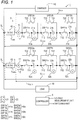
- a battery system 1 shown in Fig. 1 is, for example, a device that supplies power obtained by reusing a deteriorated battery.
- the battery system 1 includes a plurality of battery packs 21 and 22 and a battery control unit 3.
- the plurality of battery packs 21 and 22 are connected in parallel to each other, and are connected to a load 10 and a charger 40 (power source).
- a charger 40 power source
- the number of the battery packs 21 and 22 may be plural, and may be three or more.
- the battery pack 21 includes a plurality of batteries 21a to 21c.
- the battery pack 22 includes a plurality of batteries 22a to 22c.
- the number of the batteries 21a to 21c, 22a to 22c may be plural, and may be two or four or more.
- Each of the plurality of batteries 21a to 21c, 22a to 22c is a chargeable and dischargeable storage battery, and may include one cell, or may include a plurality of cells.
- the battery control unit 3 includes a plurality of switching units 41a to 41c, 42a to 42c, a plurality of voltage measurement units 51a to 51c, 52a to 52c, a plurality of bidirectional DC/DC converters 61 and 62 (bidirectional voltage converter), a plurality of current measurement units 71 and 72, and a controller 8.
- the plurality of switching units 41a to 41c are provided corresponding to the plurality of batteries 21a to 21c, respectively.
- the plurality of switching units 42a to 42c are provided corresponding to the plurality of batteries 22a to 22c, respectively.
- the plurality of switching units 41a to 41c, 42a to 42c have the same configuration.
- the switching units 41a to 41c, 42a to 42c are switchable between a connected state where corresponding batteries 21a to 21c, 22a to 22c are connected in series with other batteries 21a to 21c, 22a to 22c and a non-connected state where the corresponding batteries 21a to 21c, 22a to 22c are disconnected from series connection with other batteries 21a to 21c, 22a to 22c.
- the batteries 21a to 21c, 22a to 22c switched to the connected state by the switching units 41a to 41c, 42a to 42c are connected in series and used as a power source.
- the batteries 21a to 21c, 22a to 22c switched to the non-connected state by the switching units 41a to 41c, 42a to 42c are disconnected from the batteries 21a to 21c, 22a to 22c in the connected state and are not used as the power source.
- the switching unit 41a is configured with a first switch SW11a connected in series with the battery 21a, and a second switch SW12a connected in parallel to the battery 21a and the first switch SW11a.
- One end T11 of the first switch SW11a is connected to one electrode (for example, a positive electrode) of the battery 21a.
- One end T21 of the second switch SW12a is connected to the other electrode (for example, a negative electrode) of the battery 21a, and the other end T22 of the second switch SW12a is connected to the other end T12 of the first switch SW11a. Since the switching units 41b and 41c can be described by replacing "a" in the above description of the switching unit 41a with "b” and "c", a detailed description thereof is omitted.
- the switching unit 42a is configured with a first switch SW21a connected in series with the battery 22a, and a second switch SW22a connected in parallel to the battery 22a and the first switch SW21a.
- One end T11 of the first switch SW21a is connected to one electrode (for example, a positive electrode) of the battery 22a.
- One end T21 of the second switch SW22a is connected to the other electrode (for example, a negative electrode) of the battery 22a, and the other end T22 of the second switch SW22a is connected to the other end T12 of the first switch SW21a. Since the switching units 42b and 42c can be described by replacing "a" in the above description of the switching unit 42a with "b” and "c", a detailed description thereof is omitted.
- the other end T12 of a first switch SW11b is connected to the negative electrode of the battery 21a, and the other end T12 of a first switch SW11c is connected to a negative electrode of the battery 21b. That is, the first switch SW11b is connected between the battery 21a and the battery 21b that are adjacent to each other, and the first switch SW11c is connected between the battery 21b and the battery 21c that are adjacent to each other.
- the other end T12 of a first switch SW21b is connected to the negative electrode of the battery 22a, and the other end T12 of a first switch SW21c is connected to a negative electrode of the battery 22b. That is, the first switch SW21b is connected between the battery 22a and the battery 22b that are adjacent to each other, and the first switch SW21c is connected between the battery 22b and the battery 22c that are adjacent to each other.
- the plurality of voltage measurement units 51a to 51c, 52a to 52c are provided corresponding to the plurality of batteries 21a to 21c, 22a to 22c.
- the plurality of voltage measurement units 51a to 51c, 52a to 52c measure voltages across the corresponding batteries 21a to 21c, 22a to 22c and output measurement results thereof to the controller 8 to be described later.
- the plurality of bidirectional DC/DC converters 61 and 62 are provided corresponding to the plurality of battery packs 21 and 22, respectively.
- Each of the bidirectional DC/DC converters 61 and 62 includes a first input-output terminal T 1 , a second input-output terminal T 2 , and a ground terminal T GND .
- the bidirectional DC/DC converters 61 and 62 boost and lower (convert) an input voltage (DC) input between the ground terminal T GND and the first input-output terminal T 1 , and output the converted voltage as outputs V DC21 and V DC22 (DC) from between the ground terminal T GND and the second input-output terminal T 2 .
- the bidirectional DC/DC converters 61 and 62 boost and lower (convert) an input voltage (DC) input between the ground terminal T GND and the second input-output terminal T 2 , and output the converted voltage as outputs V DC11 and V DC12 (DC) from between the ground terminal T GND and the first input-output terminal T 1 .
- the ground terminals T GND of the bidirectional DC/DC converters 61 and 62 above are connected to negative electrodes of the battery packs 21 and 22, and the first input-output terminals T 1 are connected to positive electrodes of the battery packs 21 and 22. That is, a total voltage of the battery packs 21 and 22 is input as an input voltage to the first input-output terminals T 1 of the bidirectional DC/DC converters 61 and 62.
- the total voltage of the battery packs 21 and 22 is a sum of voltages across the batteries 21a to 21c, 22a to 22c that are in the connected state in the battery packs 21 and 22.
- a voltage from the charger 40 is input as an input voltage to the second input-output terminals T 2 of the bidirectional DC/DC converters 61 and 62.
- the positive electrodes of the battery packs 21 and 22 are connected to each other, and are connected to the load 10 or the charger 40 via the input-output terminals T 1 and the second input-output terminals T 2 of the bidirectional DC/DC converters 61 and 62.
- the bidirectional DC/DC converters 61 and 62 boost and lower the total voltage of the battery packs 21 and 22 during discharge, and output the voltage to the load 10.
- the bidirectional DC/DC converters 61 and 62 boost and lower a voltage from the charger 40 during charge, and output the voltage to the battery packs 21 and 22.
- the bidirectional DC/DC converters 61 and 62 are connected to the controller 8, and can control the outputs V DC11 , V DC12 , V DC21 , and V DC22 of the bidirectional DC/DC converters 61 and 62 by the controller 8.
- the plurality of current measurement units 71 and 72 are provided corresponding to the plurality of battery packs 21 and 22, respectively.
- the current measurement unit 71 is connected in series with the battery pack 21, and measures a current I1 (charge current or discharge current) flowing through the battery pack 21.
- the current measurement unit 72 is connected in series with the battery pack 22, and measures a current 12 flowing through the battery pack 22.
- the controller 8 includes a well-known CPU, ROM, and RAM, and controls the entire battery system 1.
- the controller 8 functions as a first controller, and controls ON/OFF of the first switches SW11a to SW11c, the SW21a to SW21c, the second switches SW12a to SW12c, SW22a to SW22c based on a voltage across each of the batteries 21a to 21c, 22a to 22c. More specifically, the controller 8 bypasses the batteries 21a to 21c, 22a to 22c that reach a discharge termination voltage or a charge termination voltage during the discharge or the charge as a non-connected state.
- the controller 8 controls the DC/DC converters 61 and 62 as described below.
- the controller 8 first controls the outputs V DC11 and V DC12 of the DC/DC converters 61 and 62 based on charging states of the battery packs 21 and 22.
- the total voltage is the sum of the voltages across the batteries 21a to 21c, 22a to 22c that are in the connected state in the battery packs 21 and 22, and is a voltage corresponding to the charging state.
- the controller 8 controls the DC/DC converter 61 so that the output V DC11 becomes a voltage slightly higher than the total voltage of the battery pack 21.
- the controller 8 controls the DC/DC converter 62 so that the output V DC12 becomes a voltage slightly higher than the total voltage of the battery pack 22. Accordingly, both of the battery packs 21 and 22 start charging at the same time.
- the controller 8 controls the outputs V DC11 and V DC12 of the DC/DC converters 61 and 62 based on the charge currents I1 and I2 measured by the current measurement units 71 and 72. More specifically, the controller 8 adjusts the outputs V DC11 and V DC12 of the bidirectional DC/DC converters 61 and 62 so that the charge currents I1 and 12 within a predetermined range (equal to or less than an allowable maximum input current and equal to or larger than a lower limit input current) flow through the battery packs 21 and 22.
- a predetermined range equal to or less than an allowable maximum input current and equal to or larger than a lower limit input current
- the controller 8 raises the output V DC11 until the charge current I1 equal to or larger than the lower limit input current flows, and when the charge current I1 larger than the allowable maximum input current flows, the controller 8 decreases the output V DC11 .
- the controller 8 raises the output V DC12 until the charge current 12 equal to or larger than the lower limit input current flows, and when the charge current 12 larger than the allowable maximum input current flows, the controller 8 decreases the output V DC12 .
- the battery packs 21 and 22 having different total voltages can be charged at the same time.
- the controller 8 controls the DC/DC converters 61 and 62 as described below.
- the controller 8 controls the outputs V DC21 and V DC22 of the bidirectional DC/DC converters 61 and 62 to a predetermined constant value in accordance with the load 10. Accordingly, since the outputs V DC21 and V DC22 are controlled to be equivalent, when the battery packs 21 and 22 are connected to the load 10, the battery packs 21 and 22 can be discharged at the same time, and the efficiency of the discharge can be improved.
- the DC/DC converters 61 and 62 try to keep the outputs V DC21 and V DC22 at a constant value, so that the discharge currents I1 and I2 increase as the discharge progresses.
- the controller 8 controls reductions of the DC/DC converters 61 and 62 so as to reduce the outputs V DC21 and V DC22 .
- the outputs V DC21 and V DC22 decrease, so that the discharge currents I1 and I2 also reduce.
- the allowable current is determined for each of the battery packs 21 and 22. More specifically, a relationship between a battery state such as a battery temperature, a degradation state (for example, internal resistor), a charging state (for example, an open circuit voltage), and the allowable current is stored in advance in a memory or the like.
- the allowable current of the battery pack 21 is set to the minimum value among each allowable currents of the batteries 21a to 21c in the connected state.
- the allowable current of the battery pack 22 is set to the minimum value among each allowable currents of the battery states of the batteries 22a to 22c in the connected state.
- the bidirectional DC/DC converters 61 and 62 are electrically converted from electricity to magnetism, and from magnetism to electricity, electrical insulation is possible for each battery pack 21 and 22.
- Fig. 2 is a flowchart showing a charge processing procedure of the controller 8 shown in Fig. 1 .
- the controller 8 executes a charge processing when a charge signal is received from an external system or the like.
- the controller 8 turns off all the first switches SW11a to SW11c, SW21a to SW21c, and all the second switches SW12a to SW12c, SW22a to SW22c (step S1).
- the controller 8 turns on all the first switches SW11a to SW11c, SW21a to SW21c (step S2).
- the controller 8 connects the charger 40 to the battery packs 21 and 22 to start charging (step S3).
- the controller 8 controls the outputs V DC11 and V DC12 of the DC/DC converters 61 and 62 so as to have a value corresponding to the charging states of the battery packs 21 and 22 as described above (step S4).
- the controller 8 acquires the charge currents I1 and I2 flowing through the battery packs 21 and 22 measured by the current measurement units 71 and 72, and controls the outputs V DC11 and V DC12 so that the acquired charge currents I1 and I2 fall within a predetermined range (step S5).
- the controller 8 acquire voltage values of the batteries 21a to 21c, 22a to 22c measured by the voltage measurement units 51a to 51c, 52a to 52c, and determines whether the batteries 21a to 21c, 22a to 22c reach the charge termination voltage (step S6). If the batteries 21a to 21c, 22a to 22c that reach the charge termination voltage are not present (N in step S6), the controller 8 returns to step S5.
- step S6 determines whether all the batteries 21a to 21c, 22a to 22c reach the charge termination voltage.
- step S7 If all the batteries 21a to 21c, 22a to 22c do not reach the charge termination voltage (N in step S7), the controller 8 turns off the first switches SW11a to SW11c, SW21a to SW21c corresponding to the batteries 21a to 21c, 22a to 22c determined to have reached the charge termination voltage, turns on the second switches SW12a to SW12c, SW22a to SW22c, bypasses the batteries 21a to 21c, 22a to 22c that reach the charge termination voltage (step S8), and then returns to step S5.
- step S7 the controller 8 disconnects the charger 40 and stops charging (step S9), and turns off all the first switches SW11a to SW11c, SW21a to SW21c, and all the second switches SW12a to SW12c, SW22a to SW22c (step S10). Thereafter, the controller 8 turns on all the first switches SW11a to SW11c, SW21a to SW21c (step S11), and then ends the charge processing.
- Fig. 3 is a flowchart showing a discharge processing procedure of the controller 8 shown in Fig. 1 .
- the controller 8 executes a discharge processing when a discharge signal is received from an external system or the like.
- the controller 8 executes steps S1 and S2 similarly to the charge processing.
- the controller 8 connects the load 10 to the battery packs 21 and 22 to start discharging (step S12). Thereafter, the controller 8 controls the outputs V DC21 and V DC22 of the bidirectional DC/DC converters 61 and 62 to a predetermined constant value equal to each other (step S13). Next, the controller 8 acquires the currents flowing through the battery packs 21 and 22 measured by the current measurement units 71 and 72, and compares the currents with a predetermined allowable maximum current (threshold value) (step S14).
- step S14 If a current flows exceeding the allowable maximum current among the battery packs 21 and 22 (Y in step S14), the controller 8 decreases the outputs V DC21 and V DC22 of the DC/DC converters 61 and 62 corresponding to the battery packs 21 and 22 exceeding the allowable maximum current (step S15), and proceeds to step S18. In step S15, the controller 8 decreases the outputs V DC21 and V DC22 until the discharge currents I1 and I2 flowing through the battery packs 21 and 22 fall within the allowable maximum current.
- step S16 determination as to whether the current is sufficiently low can be considered based on whether the current flowing through the battery packs 21 and 22 is equal to or less than a set current value less than the allowable maximum current.
- step S16 If none of the battery packs 21 and 22 exceed the allowable maximum current, and none are sufficiently low (N in step S16), the controller 8 immediately proceeds to step S18.
- the controller 8 in step S18 acquires voltages of the batteries 21a to 21c, 22a to 22c measured by the voltage measurement units 51a to 51c, 52a to 52c, and determines whether the batteries 21a to 21c, 22a to 22c reach the discharge termination voltage. If the batteries 21a to 21c, 22a to 22c that reach the discharge termination voltage are not present (N in step S18), the controller 8 returns to step S14.
- step S18 determines whether all the batteries 21a to 21c, 22a to 22c reach the discharge termination voltage (step S19).
- the controller 8 turns off the first switches SW11a to SW11c, SW21a to SW21c corresponding to the batteries 21a to 21c, 22a to 22c determined to have reached the discharge termination voltage, turns on the second switches SW12a to SW12c, SW22a to SW22c, bypasses the batteries 21a to 21c, 22a to 22c that reach the discharge termination voltage (step S20), and then returns to step S14.
- step S19 When all the batteries 21a to 21c, 22a to 22c reach the discharge termination voltage (Y in step S19), the controller 8 disconnects the discharge from the load 10 (step S21), executes steps S10 and S11 in a similar manner as the charge processing, and ends the discharge processing.
- the bidirectional DC/DC converters 61 and 62 are provided for each of the plurality of battery packs, and the ground terminal T GND and the first input-output terminal T 1 are connected to both ends of the corresponding battery packs 21 and 22.
- the positive electrodes of the battery packs 21 and 22 are connected to each other via the first input-output terminals T 1 and the second input-output terminals T 2 . Accordingly, the bidirectional DC/DC converters 61 and 62 can boost and lower the total voltage of the battery packs 21 and 22 or the input voltage from the charger 40, and charge or discharge the plurality of battery packs 21 and 22 at the same time, thereby improving the efficiency of charging or discharging.
- the controller 8 controls the outputs V DC11 and V DC12 so that the charge currents I1 and I2 in a predetermined range flow through the plurality of battery packs 21 and 22 during the charge. Accordingly, the plurality of battery packs 21 and 22 can be charged at the same time, and the charge can be performed more efficiently.
- the controller 8 controls the outputs V DC11 and V DC12 to a value corresponding to the charging states of the plurality of battery packs 21 and 22 when the charge is started, and then controls the output from the first input-output terminal T 1 so that the charge currents I1 and I2 in the predetermined range flow through the plurality of battery packs 21 and 22. Accordingly, it is possible to rapidly make the charge currents I1 and I2 flow through the plurality of battery packs 21 and 22 when the charging is started.
- the controller 8 controls the outputs V DC21 and V DC22 to have a predetermined value during the discharge. Accordingly, the plurality of battery packs 21 and 22 can be discharged at the same time, and the discharge can be performed more efficiently.
- the controller 8 controls the reductions of the DC/DC converters 61 and 62 so as to reduce the outputs V DC21 and V DC22 . Accordingly, the discharge currents I1 and I2 flowing through the battery packs 21 and 22 can be reduced to be equal to or less than the allowable maximum current.
- the controller 8 controls the outputs V DC11 and V DC12 based on the charging states of the battery packs 21 and 22 when the charge is started, and then controls the outputs V DC11 and V DC12 based on the charge currents I1 and 12, but the present invention is not limited thereto.
- the controller 8 may control the outputs V DC11 and V DC12 based on the charge currents I1 and I2 from the start of charging.
- the controller 8 may set the outputs V DC11 and V DC12 from the first input-output terminal T 1 to 0 when the charge is started, and increase the outputs V DC11 and V DC12 until the charge currents I1 and I2 fall within a predetermined range.
- the switching units 41a to 41c, 42a to 42c include the first switches SW11a to SW11c, SW21a to SW21c, and the second switches SW12a to SW12c, SW22a to SW22c, but the present invention is not limited thereto.
- the switching units 41a to 41c, 42a to 42c may include a changeover switch for selecting one of the batteries 21a to 21c, 22a to 22c and a bypass circuit connected in parallel to the batteries 21a to 21c, 22a to 22c.
- the bidirectional DC/DC converters 61 and 62 are provided for each of the battery packs 21 and 22, but the present invention is not limited thereto.
- unidirectional DC/DC converters 81 and 82 (voltage converters) may be provided instead of the bidirectional DC/DC converters 61 and 62.
- the DC/DC converters 81 and 82 include a ground terminal T GND , an input terminal T IN , and an output terminal T OUT , converts a voltage input between the ground terminal T GND and the input terminal T IN and outputs the converted voltage from the ground terminal T GND and the output terminal T OUT .
- the ground terminal T GND and the input terminal T IN are connected to both ends of the battery packs 21 and 22, and one ends of the battery packs 21 and 22 are connected to each other via the input terminals T IN and the output terminals T OUT .
- the DC/DC converters 81 and 82 are controlled similarly as the bidirectional DC/DC converters 61 and 62 during the discharge according to the embodiment described above.
- the ground terminal T GND and the output terminal T OUT are connected to both ends of the battery packs 21 and 22, and one ends of the battery packs 21 and 22 are connected to each other via the input terminals T IN and the output terminals T OUT .
- the DC/DC converters 81 and 82 are controlled similarly as the bidirectional DC/DC converters 61 and 62 during the charge according to the embodiment described above.
- the unidirectional DC/DC converters 81 and 82 shown in Fig. 4 and the unidirectional DC/DC converters 81 and 82 shown in Fig. 5 may be connected in parallel to perform voltage conversion in both directions.
- the DC/DC converters 61, 62, 81, and 82 are used as the voltage converters, but the present invention is not limited thereto.
- a series regulator may be used as the voltage converter.
Abstract
Description
- The present invention relates to a battery control unit and a battery system.
- There is a battery system configured by connecting a plurality of batteries in series. Deterioration of the plurality of batteries varies due to, for example, a variation in manufacturing or a variation in an operation environment. For example, a battery close to a heat source deteriorates rapidly, while a battery away from the heat source deteriorates slowly.
- Therefore, a battery that is deteriorated during charge and discharge reaches charge and discharge termination voltages first. In this case, even when there is remaining capacity in other batteries, the charge and the discharge must be stopped. Therefore, a system that bypasses a battery that has reached the charge termination voltage, disconnects the battery from charging, and continues the charge of a battery that has not reached the charge termination voltage is proposed (Patent Literature 1). Similarly, during the discharge, a battery system that bypasses a battery that has reached the discharge termination voltage, disconnects the battery from discharging, and continues the discharge of a battery that has not reached the discharge termination voltage can be considered.
- However, in the battery system in the related art described above, a power supply to a load is stopped every time a bypass state of the battery is switched during the discharge. A plurality of battery packs including a plurality of batteries connected in parallel can be considered so that even if one of the plurality of battery packs is bypass-switched, a rest can maintain the power supply to the load.
- [Patent Literature 1]
JP-A-2013-31249 - However, in the related art described above, since the battery is used as a bypass, when the battery packs are connected in parallel, a large difference is generated in a total voltage between the battery packs. Therefore, only a battery pack having the highest total voltage can be discharged. Only a battery pack having the lowest total voltage can be charged, and efficiency of charging and discharging is not good.
- One or more embodiments provide a battery control unit and a battery system that improve efficiency of charging or discharging.
- [1] A battery control unit includes a plurality of switching units, a first controller, and a plurality of bidirectional voltage converters including a ground terminal, a first, and a second input-output terminal. Each of a plurality of battery packs connected in parallel to each other includes a plurality of batteries connected in series with each other. The plurality of switching units are disposed corresponding to the plurality of batteries respectively, and are configured to switch between a connected state where a corresponding battery among the plurality of batteries is connected in series with non-corresponding battery among the plurality of batteries and a non-connected state where the corresponding battery is disconnected from series connection with the non-corresponding battery. The first controller is configured to control the plurality of switching units corresponding to the battery, which is determined to reach a termination voltage during charge or discharge, to the non-connected state. The plurality of bidirectional voltage converters are configured to convert a first input voltage input between the first input-output terminal and the ground terminal and output a first converted voltage from between the second input-output terminal and the ground terminal, and convert a second input voltage input between the second input-output terminal and the ground terminal and output a second converted voltage from between the first input-output terminal and the ground terminal. The plurality of bidirectional voltage converters are disposed corresponding to the plurality of battery packs, and the first input-output terminals are connected to one end of a corresponding battery pack and the ground terminals are connected to another end of the corresponding battery pack, respectively. The one ends of the plurality of battery packs are connected to each other via the first input-output terminals and the second input-output terminals.
- [2] The battery control unit may further comprise a second controller configured to control output voltages from the first input-output terminals of the plurality of bidirectional voltage converters. The second controller may control the output voltages from the first input-output terminals such that charge currents in a predetermined range flow through the plurality of battery packs during the charge.
- [3] The second controller may control the output voltages from the first input-output terminals to a value based on charging states of the plurality of battery packs when the charge is started, and controls the output voltages from the first input-output terminals such that the charge currents in the predetermined range flow through the plurality of battery packs.
- [4] The battery control unit may further comprise a second controller configured to control output voltages from the second input-output terminals of the plurality of bidirectional voltage converters. The second controller controls the output voltages from the second input-output terminals to a predetermined value during the discharge.
- [5] When a discharge current flowing through the battery pack exceeds a threshold value during the discharge, the second controller may be configured to control to reduce the output voltage from the second input-output terminal of the bidirectional voltage converter corresponding to the battery pack in which discharge current exceeds the threshold value.
- [6] A battery control unit includes a plurality of switching units, a first controller, and a plurality of voltage converters including a ground terminal, an input terminal, and an output terminal. The plurality of switching units are disposed corresponding to the plurality of batteries respectively, and are configured to switch between a connected state where a corresponding battery among the plurality of batteries is connected in series with non-corresponding battery and a non-connected state where the corresponding battery is disconnected from series connection with the non-corresponding battery. The first controller is configured to control the plurality of switching units corresponding to the battery, which is determined to reach a termination voltage during charge or discharge, to the non-connected state. The plurality of voltage converters are configured to convert a input voltage input between the input terminal and the ground terminal and output a converted voltage from between the output terminal and the ground terminal. The voltage converters are disposed corresponding to the plurality of battery packs, and the input terminals or the output terminals are connected to one ends of a corresponding battery pack, and the ground terminals are connected to another end of the corresponding battery pack, respectively. One ends of the plurality of battery packs are connected to each other via input terminals and output terminals.
- [7] A battery system may include a plurality of battery packs having a plurality of batteries connected in series, the plurality of battery packs being connected in parallel to each other, and the battery control unit according to any one of [1] to [6].
- According to the battery control unit having the configuration of the above [1], the bidirectional voltage converter is provided for each of the plurality of battery packs, and the ground terminal and the first input-output terminal are connected to both ends of the corresponding battery pack. One ends of the battery packs are connected to each other via the first input-output terminals and the second input-output terminals. Accordingly, each bidirectional voltage converter boosts or lowers a total voltage of the battery pack or an input voltage input to the battery pack to allow the plurality of battery packs to be charged or discharged at the same time. Accordingly, it is possible to improve efficiency of charging or discharging.
- According to the battery control unit having the configuration of the above [2], the second controller controls the output from the first input-output terminal such that the charge current in the predetermined range flows through the plurality of battery packs during the charge. Accordingly, the plurality of battery packs can be charged at the same time, and the charge can be performed more efficiently.
- According to the battery control unit having the configuration of the above [3], the second controller controls the output from the first input-output terminal to the value corresponding to charging states of the plurality of battery packs when the charge is started, and then controls the output from the first input-output terminal such that the charge current in the predetermined range flows through the plurality of battery packs. Accordingly, it is possible to rapidly make the charge current flow through the plurality of battery packs when the charge is started.
- According to the battery control unit having the configuration of the above [4], the second controller controls the output from the second input-output terminal to a predetermined value during the discharge. Accordingly, the plurality of battery packs can be discharged at the same time, and the discharge can be performed more efficiently.
- According to the battery control unit having the configuration of the above [5], the second controller performs control so as to reduce the output from the second input-output terminal when the discharge current flowing through the plurality of battery packs exceeds the threshold value during the discharge. Accordingly, the discharge current flowing through the battery pack can be reduced to be equal to or less than the threshold value.
- According to the battery control unit having the configuration of the above [6], the voltage converter is provided for each of the plurality of battery packs, and the ground terminal and one of the input terminal and the output terminal are connected to the both ends of the corresponding battery pack. One ends of the battery packs are connected to each other via the input terminals and the output terminals. Accordingly, each voltage converter boosts or lowers the total voltage of the battery pack or the input voltage input to the battery pack to allow the plurality of battery packs to be charged or discharged at the same time. Accordingly, it is possible to improve efficiency of charging or discharging.
- According to the battery system having the configuration of the above [7], it is possible to improve efficiency of charging or discharging.
- According to one or more embodiments, it is possible to provide a battery control unit and a battery system capable of improving efficiency of charging or discharging.
- The present invention has been briefly described as above. Details of the present invention is further clarified by reading a mode for carrying out the invention described below with reference to attached drawings.
-
-
Fig. 1 is a circuit diagram showing a battery system. -
Fig. 2 is a flowchart showing a charge processing procedure of a controller shown inFig. 1 . -
Fig. 3 is a flowchart showing a discharge processing procedure of the controller shown inFig. 1 . -
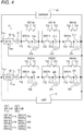
Fig. 4 is a circuit diagram showing a battery system according to another embodiment. -
Fig. 5 is a circuit diagram showing a battery system according to another embodiment. - A specific embodiment according to the present invention will be described below with reference to the drawings.
- A battery system 1 shown in
Fig. 1 is, for example, a device that supplies power obtained by reusing a deteriorated battery. - As shown in
Fig. 1 , the battery system 1 includes a plurality of battery packs 21 and 22 and a battery control unit 3. The plurality of battery packs 21 and 22 are connected in parallel to each other, and are connected to aload 10 and a charger 40 (power source). In the present embodiment, in order to simplify a description, an example in which two battery packs 21 and 22 are connected in parallel will be described, but the present invention is not limited thereto. The number of the battery packs 21 and 22 may be plural, and may be three or more. - The
battery pack 21 includes a plurality ofbatteries 21a to 21c. Thebattery pack 22 includes a plurality ofbatteries 22a to 22c. In the present embodiment, in order to simplify a description, an example in which threebatteries 21a to 21c, 22a to 22c are connected in series will be described, but the present invention is not limited thereto. The number of thebatteries 21a to 21c, 22a to 22c may be plural, and may be two or four or more. Each of the plurality ofbatteries 21a to 21c, 22a to 22c is a chargeable and dischargeable storage battery, and may include one cell, or may include a plurality of cells. - The battery control unit 3 includes a plurality of switching
units 41a to 41c, 42a to 42c, a plurality ofvoltage measurement units 51a to 51c, 52a to 52c, a plurality of bidirectional DC/DC converters 61 and 62 (bidirectional voltage converter), a plurality ofcurrent measurement units controller 8. - The plurality of switching
units 41a to 41c are provided corresponding to the plurality ofbatteries 21a to 21c, respectively. The plurality of switchingunits 42a to 42c are provided corresponding to the plurality ofbatteries 22a to 22c, respectively. The plurality of switchingunits 41a to 41c, 42a to 42c have the same configuration. - The switching
units 41a to 41c, 42a to 42c are switchable between a connected state where correspondingbatteries 21a to 21c, 22a to 22c are connected in series withother batteries 21a to 21c, 22a to 22c and a non-connected state where the correspondingbatteries 21a to 21c, 22a to 22c are disconnected from series connection withother batteries 21a to 21c, 22a to 22c. Specifically, thebatteries 21a to 21c, 22a to 22c switched to the connected state by the switchingunits 41a to 41c, 42a to 42c are connected in series and used as a power source. On the other hand, thebatteries 21a to 21c, 22a to 22c switched to the non-connected state by the switchingunits 41a to 41c, 42a to 42c are disconnected from thebatteries 21a to 21c, 22a to 22c in the connected state and are not used as the power source. - The
switching unit 41a is configured with a first switch SW11a connected in series with thebattery 21a, and a second switch SW12a connected in parallel to thebattery 21a and the first switch SW11a. One end T11 of the first switch SW11a is connected to one electrode (for example, a positive electrode) of thebattery 21a. One end T21 of the second switch SW12a is connected to the other electrode (for example, a negative electrode) of thebattery 21a, and the other end T22 of the second switch SW12a is connected to the other end T12 of the first switch SW11a. Since the switchingunits switching unit 41a with "b" and "c", a detailed description thereof is omitted. - The
switching unit 42a is configured with a first switch SW21a connected in series with thebattery 22a, and a second switch SW22a connected in parallel to thebattery 22a and the first switch SW21a. One end T11 of the first switch SW21a is connected to one electrode (for example, a positive electrode) of thebattery 22a. One end T21 of the second switch SW22a is connected to the other electrode (for example, a negative electrode) of thebattery 22a, and the other end T22 of the second switch SW22a is connected to the other end T12 of the first switch SW21a. Since the switchingunits switching unit 42a with "b" and "c", a detailed description thereof is omitted. - The other end T12 of a first switch SW11b is connected to the negative electrode of the
battery 21a, and the other end T12 of a first switch SW11c is connected to a negative electrode of thebattery 21b. That is, the first switch SW11b is connected between thebattery 21a and thebattery 21b that are adjacent to each other, and the first switch SW11c is connected between thebattery 21b and thebattery 21c that are adjacent to each other. - The other end T12 of a first switch SW21b is connected to the negative electrode of the
battery 22a, and the other end T12 of a first switch SW21c is connected to a negative electrode of thebattery 22b. That is, the first switch SW21b is connected between thebattery 22a and thebattery 22b that are adjacent to each other, and the first switch SW21c is connected between thebattery 22b and thebattery 22c that are adjacent to each other. - According to the above configuration, when the second switches SW12a to SW12c, SW22a to SW22c are turned off and the first switches SW11a to SW11c, SW21a to SW21c are turned on, the corresponding
batteries 21a to 21c, 22a to 22c are in the connected state. In addition, when the first switches SW11a to SW11c, SW21a to SW21c are turned off, the correspondingbatteries 21a to 21c, 22a to 22c are in the non-connected state. At this time, when the second switches SW12a to SW12c, SW22a to SW22c are turned on, a bypass path is formed, and only thebatteries 21a to 21c, 22a to 22c in the connected state are connected in series. - The plurality of
voltage measurement units 51a to 51c, 52a to 52c are provided corresponding to the plurality ofbatteries 21a to 21c, 22a to 22c. The plurality ofvoltage measurement units 51a to 51c, 52a to 52c measure voltages across the correspondingbatteries 21a to 21c, 22a to 22c and output measurement results thereof to thecontroller 8 to be described later. - The plurality of bidirectional DC/
DC converters DC converters DC converters DC converters - The ground terminals TGND of the bidirectional DC/
DC converters DC converters batteries 21a to 21c, 22a to 22c that are in the connected state in the battery packs 21 and 22. A voltage from thecharger 40 is input as an input voltage to the second input-output terminals T2 of the bidirectional DC/DC converters load 10 or thecharger 40 via the input-output terminals T1 and the second input-output terminals T2 of the bidirectional DC/DC converters DC converters load 10. The bidirectional DC/DC converters charger 40 during charge, and output the voltage to the battery packs 21 and 22. - The bidirectional DC/
DC converters controller 8, and can control the outputs VDC11, VDC12, VDC21, and VDC22 of the bidirectional DC/DC converters controller 8. - The plurality of
current measurement units current measurement unit 71 is connected in series with thebattery pack 21, and measures a current I1 (charge current or discharge current) flowing through thebattery pack 21. Thecurrent measurement unit 72 is connected in series with thebattery pack 22, and measures a current 12 flowing through thebattery pack 22. - The
controller 8 includes a well-known CPU, ROM, and RAM, and controls the entire battery system 1. Thecontroller 8 functions as a first controller, and controls ON/OFF of the first switches SW11a to SW11c, the SW21a to SW21c, the second switches SW12a to SW12c, SW22a to SW22c based on a voltage across each of thebatteries 21a to 21c, 22a to 22c. More specifically, thecontroller 8 bypasses thebatteries 21a to 21c, 22a to 22c that reach a discharge termination voltage or a charge termination voltage during the discharge or the charge as a non-connected state. - During the charge, the
controller 8 controls the DC/DC converters controller 8 first controls the outputs VDC11 and VDC12 of the DC/DC converters batteries 21a to 22c, 22a to 22c can be used. The total voltage is the sum of the voltages across thebatteries 21a to 21c, 22a to 22c that are in the connected state in the battery packs 21 and 22, and is a voltage corresponding to the charging state. Thecontroller 8 controls the DC/DC converter 61 so that the output VDC11 becomes a voltage slightly higher than the total voltage of thebattery pack 21. Similarly, thecontroller 8 controls the DC/DC converter 62 so that the output VDC12 becomes a voltage slightly higher than the total voltage of thebattery pack 22. Accordingly, both of the battery packs 21 and 22 start charging at the same time. - Thereafter, the
controller 8 controls the outputs VDC11 and VDC12 of the DC/DC converters current measurement units controller 8 adjusts the outputs VDC11 and VDC12 of the bidirectional DC/DC converters battery pack 21, thecontroller 8 raises the output VDC11 until the charge current I1 equal to or larger than the lower limit input current flows, and when the charge current I1 larger than the allowable maximum input current flows, thecontroller 8 decreases the output VDC11. Similarly, when only the charge current 12 smaller than the lower limit input current flows through thebattery pack 22, thecontroller 8 raises the output VDC12 until the charge current 12 equal to or larger than the lower limit input current flows, and when the charge current 12 larger than the allowable maximum input current flows, thecontroller 8 decreases the output VDC12. - Accordingly, the battery packs 21 and 22 having different total voltages can be charged at the same time.
- During the discharge, the
controller 8 controls the DC/DC converters controller 8 controls the outputs VDC21 and VDC22 of the bidirectional DC/DC converters load 10. Accordingly, since the outputs VDC21 and VDC22 are controlled to be equivalent, when the battery packs 21 and 22 are connected to theload 10, the battery packs 21 and 22 can be discharged at the same time, and the efficiency of the discharge can be improved. - When the discharge progresses under a constant load, the total voltage of the battery packs 21 and 22 reduces. Therefore, the DC/
DC converters controller 8 controls reductions of the DC/DC converters DC converters - The allowable current is determined for each of the battery packs 21 and 22. More specifically, a relationship between a battery state such as a battery temperature, a degradation state (for example, internal resistor), a charging state (for example, an open circuit voltage), and the allowable current is stored in advance in a memory or the like. The allowable current of the
battery pack 21 is set to the minimum value among each allowable currents of thebatteries 21a to 21c in the connected state. Similarly, the allowable current of thebattery pack 22 is set to the minimum value among each allowable currents of the battery states of thebatteries 22a to 22c in the connected state. - According to the battery system 1 configured as described above, since the bidirectional DC/
DC converters battery pack - Next, an operation during the charge of the battery system 1 described in the above outline will be described with reference to
Fig. 2. Fig. 2 is a flowchart showing a charge processing procedure of thecontroller 8 shown inFig. 1 . Thecontroller 8 executes a charge processing when a charge signal is received from an external system or the like. First, thecontroller 8 turns off all the first switches SW11a to SW11c, SW21a to SW21c, and all the second switches SW12a to SW12c, SW22a to SW22c (step S1). Thereafter, thecontroller 8 turns on all the first switches SW11a to SW11c, SW21a to SW21c (step S2). Next, thecontroller 8 connects thecharger 40 to the battery packs 21 and 22 to start charging (step S3). - Next, the
controller 8 controls the outputs VDC11 and VDC12 of the DC/DC converters - Thereafter, the
controller 8 acquires the charge currents I1 and I2 flowing through the battery packs 21 and 22 measured by thecurrent measurement units - Thereafter, the
controller 8 acquire voltage values of thebatteries 21a to 21c, 22a to 22c measured by thevoltage measurement units 51a to 51c, 52a to 52c, and determines whether thebatteries 21a to 21c, 22a to 22c reach the charge termination voltage (step S6). If thebatteries 21a to 21c, 22a to 22c that reach the charge termination voltage are not present (N in step S6), thecontroller 8 returns to step S5. - On the other hand, if a battery among the
batteries 21a to 21c, 22a to 22c that reaches the charge termination voltage is present (Y in step S6), thecontroller 8 determines whether all thebatteries 21a to 21c, 22a to 22c reach the charge termination voltage (step S7). If all thebatteries 21a to 21c, 22a to 22c do not reach the charge termination voltage (N in step S7), thecontroller 8 turns off the first switches SW11a to SW11c, SW21a to SW21c corresponding to thebatteries 21a to 21c, 22a to 22c determined to have reached the charge termination voltage, turns on the second switches SW12a to SW12c, SW22a to SW22c, bypasses thebatteries 21a to 21c, 22a to 22c that reach the charge termination voltage (step S8), and then returns to step S5. - If all the batteries reach the charge termination voltage (Y in step S7), the
controller 8 disconnects thecharger 40 and stops charging (step S9), and turns off all the first switches SW11a to SW11c, SW21a to SW21c, and all the second switches SW12a to SW12c, SW22a to SW22c (step S10). Thereafter, thecontroller 8 turns on all the first switches SW11a to SW11c, SW21a to SW21c (step S11), and then ends the charge processing. - Next, an operation during the discharge of the battery system 1 described in the above outline will be described with reference to
Fig. 3. Fig. 3 is a flowchart showing a discharge processing procedure of thecontroller 8 shown inFig. 1 . InFig. 3 , the same steps as those inFig. 2 described above are denoted by the same reference signs, and a detailed description thereof is omitted. Thecontroller 8 executes a discharge processing when a discharge signal is received from an external system or the like. First, thecontroller 8 executes steps S1 and S2 similarly to the charge processing. - Next, the
controller 8 connects theload 10 to the battery packs 21 and 22 to start discharging (step S12). Thereafter, thecontroller 8 controls the outputs VDC21 and VDC22 of the bidirectional DC/DC converters controller 8 acquires the currents flowing through the battery packs 21 and 22 measured by thecurrent measurement units - If a current flows exceeding the allowable maximum current among the battery packs 21 and 22 (Y in step S14), the
controller 8 decreases the outputs VDC21 and VDC22 of the DC/DC converters controller 8 decreases the outputs VDC21 and VDC22 until the discharge currents I1 and I2 flowing through the battery packs 21 and 22 fall within the allowable maximum current. - If a sufficiently low current flows with respect to the allowable maximum current among the battery packs 21 and 22 (Y in step S16), the
controller 8 proceeds to step S17. In step S17, thecontroller 8 cancels the control of decreasing the outputs VDC21 and VDC22 to the battery packs 21 and 22 in which a sufficiently low current flows, and returns to the constant value set in step S13, and then proceeds to step S18. In step S16, determination as to whether the current is sufficiently low can be considered based on whether the current flowing through the battery packs 21 and 22 is equal to or less than a set current value less than the allowable maximum current. - If none of the battery packs 21 and 22 exceed the allowable maximum current, and none are sufficiently low (N in step S16), the
controller 8 immediately proceeds to step S18. - The
controller 8 in step S18 acquires voltages of thebatteries 21a to 21c, 22a to 22c measured by thevoltage measurement units 51a to 51c, 52a to 52c, and determines whether thebatteries 21a to 21c, 22a to 22c reach the discharge termination voltage. If thebatteries 21a to 21c, 22a to 22c that reach the discharge termination voltage are not present (N in step S18), thecontroller 8 returns to step S14. - On the other hand, if a battery among the
batteries 21a to 21c, 22a to 22c that reaches the discharge termination voltage is present (Y in step S18), thecontroller 8 determines whether all thebatteries 21a to 21c, 22a to 22c reach the discharge termination voltage (step S19). If all thebatteries 21a to 21c, 22a to 22c do not reach the discharge termination voltage (N in step S19), thecontroller 8 turns off the first switches SW11a to SW11c, SW21a to SW21c corresponding to thebatteries 21a to 21c, 22a to 22c determined to have reached the discharge termination voltage, turns on the second switches SW12a to SW12c, SW22a to SW22c, bypasses thebatteries 21a to 21c, 22a to 22c that reach the discharge termination voltage (step S20), and then returns to step S14. - When all the
batteries 21a to 21c, 22a to 22c reach the discharge termination voltage (Y in step S19), thecontroller 8 disconnects the discharge from the load 10 (step S21), executes steps S10 and S11 in a similar manner as the charge processing, and ends the discharge processing. - According to the embodiment described above, the bidirectional DC/
DC converters DC converters charger 40, and charge or discharge the plurality of battery packs 21 and 22 at the same time, thereby improving the efficiency of charging or discharging. - According to the embodiment described above, the
controller 8 controls the outputs VDC11 and VDC12 so that the charge currents I1 and I2 in a predetermined range flow through the plurality of battery packs 21 and 22 during the charge. Accordingly, the plurality of battery packs 21 and 22 can be charged at the same time, and the charge can be performed more efficiently. - According to the embodiment described above, the
controller 8 controls the outputs VDC11 and VDC12 to a value corresponding to the charging states of the plurality of battery packs 21 and 22 when the charge is started, and then controls the output from the first input-output terminal T1 so that the charge currents I1 and I2 in the predetermined range flow through the plurality of battery packs 21 and 22. Accordingly, it is possible to rapidly make the charge currents I1 and I2 flow through the plurality of battery packs 21 and 22 when the charging is started. - According to the embodiment described above, the
controller 8 controls the outputs VDC21 and VDC22 to have a predetermined value during the discharge. Accordingly, the plurality of battery packs 21 and 22 can be discharged at the same time, and the discharge can be performed more efficiently. - According to the embodiment described above, when the currents flowing through the plurality of battery packs 21 and 22 exceed an allowable maximum current during the discharge, the
controller 8 controls the reductions of the DC/DC converters - The present invention is not limited to the embodiment described above, and modifications, improvements, and the like can be made as appropriate. In addition, the material, shape, size, number, arrangement position or the like of each component in the above-described embodiment are optional and are not limited as long as the present invention can be achieved.
- According to the embodiment described above, the
controller 8 controls the outputs VDC11 and VDC12 based on the charging states of the battery packs 21 and 22 when the charge is started, and then controls the outputs VDC11 and VDC12 based on the charge currents I1 and 12, but the present invention is not limited thereto. Thecontroller 8 may control the outputs VDC11 and VDC12 based on the charge currents I1 and I2 from the start of charging. As an example, thecontroller 8 may set the outputs VDC11 and VDC12 from the first input-output terminal T1 to 0 when the charge is started, and increase the outputs VDC11 and VDC12 until the charge currents I1 and I2 fall within a predetermined range. - According to the embodiment described above, the switching
units 41a to 41c, 42a to 42c include the first switches SW11a to SW11c, SW21a to SW21c, and the second switches SW12a to SW12c, SW22a to SW22c, but the present invention is not limited thereto. The switchingunits 41a to 41c, 42a to 42c may include a changeover switch for selecting one of thebatteries 21a to 21c, 22a to 22c and a bypass circuit connected in parallel to thebatteries 21a to 21c, 22a to 22c. - In addition, according to the embodiment described above, the bidirectional DC/
DC converters Figs. 4 and5 , instead of the bidirectional DC/DC converters DC converters 81 and 82 (voltage converters) may be provided. The DC/DC converters - In the example shown in
Fig. 4 , the ground terminal TGND and the input terminal TIN are connected to both ends of the battery packs 21 and 22, and one ends of the battery packs 21 and 22 are connected to each other via the input terminals TIN and the output terminals TOUT. In the example shown inFig. 4 , the DC/DC converters DC converters - In the example shown in
Fig. 5 , the ground terminal TGND and the output terminal TOUT are connected to both ends of the battery packs 21 and 22, and one ends of the battery packs 21 and 22 are connected to each other via the input terminals TIN and the output terminals TOUT. In the example shown inFig. 5 , the DC/DC converters DC converters - The unidirectional DC/
DC converters Fig. 4 and the unidirectional DC/DC converters Fig. 5 may be connected in parallel to perform voltage conversion in both directions. - In the embodiment described above, the DC/
DC converters - Here, characteristics of the embodiment of the battery control unit and the battery system according to the present invention described above will be briefly summarized in the following [1] to [7].
- [1] A battery control unit (3) includes:
- a plurality of switching units (41a to 41c, 42a to 42c);
- a first controller (8); and
- a plurality of bidirectional voltage converters (61, 62) including a ground terminal (TGND), a first input-output terminal (T1), and a second input-output terminal (T2),
- wherein each of a plurality of battery packs (21, 22) connected in parallel to each other includes a plurality of batteries (21a to 21c, 22a to 22c) connected in series with each other,
- wherein the plurality of switching units (41a to 41c, 42a to 42c) are disposed corresponding to the plurality of batteries (21a to 21c, 22a to 22c) respectively, and are configured to switch between a connected state where a corresponding battery (21a to 21c, 22a to 22c) among the plurality of batteries (21a to 21c, 22a to 22c) is connected in series with non-corresponding battery (21a to 21c, 22a to 22c) and a non-connected state where the corresponding battery (21a to 21c, 22a to 22c) is disconnected from series connection with the non-corresponding battery (21a to 21c, 22a to 22c),
- wherein the first controller (8) is configured to control the plurality of switching units (41a to 41c, 42a to 42c) corresponding to the battery (21a to 21c, 22a to 22c), which is determined to reach a termination voltage during charge or discharge, to the non-connected state,
- wherein the plurality of bidirectional voltage converters (61, 62) are configured to convert a first input voltage input between the first input-output terminal (T1) and the ground terminal (TGND) and output a first converted voltage from between the second input-output terminal (T2) and the ground terminal (TGND), and convert a second input voltage input between the second input-output terminal (T2) and the ground terminal (TGND) and output a second converted voltage from between the first input-output terminal (T1) and the ground terminal (TGND),
- wherein the plurality of bidirectional voltage converters (61, 62) are disposed corresponding to the plurality of battery packs (21, 22), and the first input-output terminals (T1) are connected to one end of a corresponding battery pack (21 and 22) and the ground terminals (TGND) are connected to another end of the corresponding battery pack (21 and 22), respectively, and
- wherein the one ends of the plurality of battery packs (21 and 22) are connected to each other via the first input-output terminals (T1) and the second input-output terminals (T2).
- [2] The battery control unit (3) according to [1],
wherein the battery control unit further includes a second controller (8) configured to control output voltages (VDC11, VDC12) from the first input-output terminals (T1) of the plurality of bidirectional voltage converters (61, 62), and
wherein the second controller (8) controls the output voltages (VDC11, VDC12) from the first input-output terminals (T1) such that charge currents (I1, I2) in a predetermined range flow through the plurality of battery packs (21, 22) during the charge. - [3] The battery control unit (3) according to [2],
wherein the second controller (8) controls the output voltages (VDC11, VDC12) from the first input-output terminals (T1) to a value based on charging states of the plurality of battery packs (21, 22) when the charge is started, and controls the output voltages from the first input-output terminals (T1) such that the charge currents in the predetermined range flow through the plurality of battery packs (21, 22). - [4] The battery control unit (3) according to [1],
wherein the battery control unit further comprises a second controller (8) configured to control output voltages (VDC21, VDC22) from the second input-output terminals (T2) of the plurality of bidirectional voltage converters (61, 62), and
wherein the second controller (8) controls the output voltages (VDC21, VDC22) from the second input-output terminals (T2) to a predetermined value during the discharge. - [5] The battery control unit (3) according to [4],
wherein when a discharge current flowing through the battery pack (21, 22) exceeds a threshold value during the discharge, the second controller (8) is configured to control to reduce the output voltage (VDC21, VDC22) from the second input-output terminal (T2) of the bidirectional voltage converter (61, 62) corresponding to the battery pack (21, 22) in which discharge current exceeds the threshold value. - [6] A battery control unit (3) includes:
- a plurality of switching units (41a to 41c, 42a to 42c);
- a first controller (8); and
- a plurality of voltage converters (81, 82) including a ground terminal (TGND), an input terminal (TIN), and an output terminal (TOUT)
- wherein the plurality of switching units (41a to 41c, 42a to 42c) are disposed corresponding to the plurality of batteries (21a to 21c, 22a to 22c) respectively, and are configured to switch between a connected state where a corresponding battery (21a to 21c, 22a to 22c) among the plurality of batteries (21a to 21c, 22a to 22c) is connected in series with non-corresponding battery (21a to 21c, 22a to 22c) and a non-connected state where the corresponding battery (21a to 21c, 22a to 22c) is disconnected from series connection with the non-corresponding battery (21a to 21c, 22a to 22c),
- wherein the first controller (8) is configured to control the plurality of switching units (41a to 41c, 42a to 42c) corresponding to the battery (21a to 21c, 22a to 22c), which is determined to reach a termination voltage during charge or discharge, to the non-connected state,
- wherein the plurality of voltage converters (81, 82) are configured to convert a input voltage input between the input terminal (TIN) and the ground terminal (TGND) and output a converted voltage from between the output terminal (TOUT) and the ground terminal (TGND),
- wherein the voltage converters (81, 82) are disposed corresponding to the plurality of battery packs (21, 22), and the input terminals (TIN) or the output terminals (TOUT) are connected to one ends of a corresponding battery pack (21, 22), and the ground terminals (TGND) are connected to another end of the corresponding battery pack (21 and 22), respectively, and
- wherein one ends of the plurality of battery packs (21, 22) are connected to each other via input terminals (TIN) and output terminals (TOUT).
- [7] A battery system (1) includes:
- a plurality of battery packs (21, 22) having a plurality of batteries (21a to 21c, 22a to 22c) connected in series, the plurality of battery packs (21, 22) being connected in parallel to each other; and
- the battery control unit (3) according to any one of [1] to [6].
-
- 1
- battery system
- 3
- battery control unit
- 8
- controller (first controller, second controller)
- 21, 22
- battery pack
- 21a to 21c
- battery
- 22a to 22c
- battery
- 41a to 41c
- switching unit
- 42a to 42c
- switching unit
- 61, 62
- bidirectional DC/DC converter (bidirectional voltage converter)
- 81, 82
- DC/DC converter (voltage converter)
- TGND
- ground terminal
- T1
- first input-output terminal
- T2
- second input-output terminal
- TIN
- input terminal
- TOUT
- output terminal
- VDC11, VDC21, VDC12, VDC22
- output
Claims (7)
- A battery control unit comprising:a plurality of switching units;a first controller; anda plurality of bidirectional voltage converters including a ground terminal, a first, and a second input-output terminal,wherein each of a plurality of battery packs connected in parallel to each other includes a plurality of batteries connected in series with each other,wherein the plurality of switching units are disposed corresponding to the plurality of batteries respectively, and are configured to switch between a connected state where a corresponding battery among the plurality of batteries is connected in series with non-corresponding battery among the plurality of batteries and a non-connected state where the corresponding battery is disconnected from series connection with the non-corresponding battery,wherein the first controller is configured to control the plurality of switching units corresponding to the battery, which is determined to reach a termination voltage during charge or discharge, to the non-connected state,wherein the plurality of bidirectional voltage converters are configured to convert a first input voltage input between the first input-output terminal and the ground terminal and output a first converted voltage from between the second input-output terminal and the ground terminal, and convert a second input voltage input between the second input-output terminal and the ground terminal and output a second converted voltage from between the first input-output terminal and the ground terminal,wherein the plurality of bidirectional voltage converters are disposed corresponding to the plurality of battery packs, and the first input-output terminals are connected to one end of a corresponding battery pack and the ground terminals are connected to another end of the corresponding battery pack, respectively, andwherein the one ends of the plurality of battery packs are connected to each other via the first input-output terminals and the second input-output terminals.
- The battery control unit according to claim 1,
wherein the battery control unit further comprises a second controller configured to control output voltages from the first input-output terminals of the plurality of bidirectional voltage converters, and
wherein the second controller controls the output voltages from the first input-output terminals such that charge currents in a predetermined range flow through the plurality of battery packs during the charge. - The battery control unit according to claim 2,
wherein the second controller controls the output voltages from the first input-output terminals to a value based on charging states of the plurality of battery packs when the charge is started, and controls the output voltages from the first input-output terminals such that the charge currents in the predetermined range flow through the plurality of battery packs. - The battery control unit according to claim 1,
wherein the battery control unit further comprises a second controller configured to control output voltages from the second input-output terminals of the plurality of bidirectional voltage converters, and
wherein the second controller controls the output voltages from the second input-output terminals to a predetermined value during the discharge. - The battery control unit according to claim 4,
wherein when a discharge current flowing through the battery pack exceeds a threshold value during the discharge, the second controller is configured to control to reduce the output voltage from the second input-output terminal of the bidirectional voltage converter corresponding to the battery pack in which discharge current exceeds the threshold value. - A battery control unit comprises:a plurality of switching units;a first controller; anda plurality of voltage converters including a ground terminal, an input terminal, and an output terminal,wherein the plurality of switching units are disposed corresponding to the plurality of batteries respectively, and are configured to switch between a connected state where a corresponding battery among the plurality of batteries is connected in series with non-corresponding battery and a non-connected state where the corresponding battery is disconnected from series connection with the non-corresponding battery,wherein the first controller is configured to control the plurality of switching units corresponding to the battery, which is determined to reach a termination voltage during charge or discharge, to the non-connected state,wherein the plurality of voltage converters are configured to convert a input voltage input between the input terminal and the ground terminal and output a converted voltage from between the output terminal and the ground terminal,wherein the voltage converters are disposed corresponding to the plurality of battery packs, and the input terminals or the output terminals are connected to one ends of a corresponding battery pack, and the ground terminals are connected to another end of the corresponding battery pack, respectively, andwherein one ends of the plurality of battery packs are connected to each other via input terminals and output terminals.
- A battery system comprises:a plurality of battery packs having a plurality of batteries connected in series, the plurality of battery packs being connected in parallel to each other; andthe battery control unit according to any one of claims 1 to 6.
Applications Claiming Priority (1)
| Application Number | Priority Date | Filing Date | Title |
|---|---|---|---|
| JP2020011532A JP7144466B2 (en) | 2020-01-28 | 2020-01-28 | Battery control unit and battery system |
Publications (2)
| Publication Number | Publication Date |
|---|---|
| EP3859936A1 true EP3859936A1 (en) | 2021-08-04 |
| EP3859936B1 EP3859936B1 (en) | 2022-06-15 |
Family
ID=74236037
Family Applications (1)
| Application Number | Title | Priority Date | Filing Date |
|---|---|---|---|
| EP21153207.2A Active EP3859936B1 (en) | 2020-01-28 | 2021-01-25 | Battery control unit and battery system |
Country Status (4)
| Country | Link |
|---|---|
| US (1) | US11489349B2 (en) |
| EP (1) | EP3859936B1 (en) |
| JP (1) | JP7144466B2 (en) |
| CN (1) | CN113258629B (en) |
Cited By (1)
| Publication number | Priority date | Publication date | Assignee | Title |
|---|---|---|---|---|
| EP4156448A1 (en) * | 2021-08-24 | 2023-03-29 | Yazaki Corporation | Storage battery control device, power storage system, and storage battery control method |
Families Citing this family (8)
| Publication number | Priority date | Publication date | Assignee | Title |
|---|---|---|---|---|
| JP7096193B2 (en) * | 2019-04-04 | 2022-07-05 | 矢崎総業株式会社 | Battery control unit and battery system |
| US11722026B2 (en) | 2019-04-23 | 2023-08-08 | Dpm Technologies Inc. | Fault tolerant rotating electric machine |
| JP7100002B2 (en) * | 2019-09-10 | 2022-07-12 | 矢崎総業株式会社 | Battery control unit and battery system |
| JP7051776B2 (en) * | 2019-09-30 | 2022-04-11 | 矢崎総業株式会社 | Battery control unit and battery system |
| US20220320876A1 (en) * | 2021-03-31 | 2022-10-06 | Baidu Usa Llc | Data center multi-stage backup system |
| CA3217299A1 (en) * | 2021-05-04 | 2022-11-10 | Tung Nguyen | Battery control systems and methods |
| CA3159864A1 (en) | 2021-05-13 | 2022-11-13 | Exro Technologies Inc. | Method and apparatus to drive coils of a multiphase electric machine |
| JP2024053666A (en) * | 2022-10-04 | 2024-04-16 | 矢崎総業株式会社 | Battery control device, power storage system, and battery control method |
Citations (5)
| Publication number | Priority date | Publication date | Assignee | Title |
|---|---|---|---|---|
| WO2012105448A1 (en) * | 2011-01-31 | 2012-08-09 | 三洋電機株式会社 | Battery module, battery system, power supply apparatus, and moving body |
| JP2013031249A (en) | 2011-07-27 | 2013-02-07 | Mitsubishi Motors Corp | Battery device charging system |
| CN106356927A (en) * | 2016-09-19 | 2017-01-25 | 华中科技大学 | Lithium battery pack SOC (state of charge) equalization system and lithium battery pack SOC equalization method |
| WO2017114802A1 (en) * | 2015-12-29 | 2017-07-06 | Vito Nv | Device and method for the reconfiguration of a rechargeable energy storage device into separate battery connection strings |
| EP3598605A1 (en) * | 2018-07-19 | 2020-01-22 | Yazaki Corporation | Battery system |
Family Cites Families (3)
| Publication number | Priority date | Publication date | Assignee | Title |
|---|---|---|---|---|
| JP4221381B2 (en) | 2005-01-19 | 2009-02-12 | Necフィールディング株式会社 | Uninterruptible power system |
| JP2013090525A (en) | 2011-10-21 | 2013-05-13 | Sanyo Electric Co Ltd | Power storage device, power supply, electric vehicle, mobile, and controller |
| US10322643B2 (en) * | 2017-05-15 | 2019-06-18 | Ford Global Technologies, Llc | Traction battery with reference supercapacitor for charge monitoring |
-
2020
- 2020-01-28 JP JP2020011532A patent/JP7144466B2/en active Active
-
2021
- 2021-01-21 US US17/155,047 patent/US11489349B2/en active Active
- 2021-01-25 EP EP21153207.2A patent/EP3859936B1/en active Active
- 2021-01-27 CN CN202110111151.4A patent/CN113258629B/en active Active
Patent Citations (5)
| Publication number | Priority date | Publication date | Assignee | Title |
|---|---|---|---|---|
| WO2012105448A1 (en) * | 2011-01-31 | 2012-08-09 | 三洋電機株式会社 | Battery module, battery system, power supply apparatus, and moving body |
| JP2013031249A (en) | 2011-07-27 | 2013-02-07 | Mitsubishi Motors Corp | Battery device charging system |
| WO2017114802A1 (en) * | 2015-12-29 | 2017-07-06 | Vito Nv | Device and method for the reconfiguration of a rechargeable energy storage device into separate battery connection strings |
| CN106356927A (en) * | 2016-09-19 | 2017-01-25 | 华中科技大学 | Lithium battery pack SOC (state of charge) equalization system and lithium battery pack SOC equalization method |
| EP3598605A1 (en) * | 2018-07-19 | 2020-01-22 | Yazaki Corporation | Battery system |
Cited By (1)
| Publication number | Priority date | Publication date | Assignee | Title |
|---|---|---|---|---|
| EP4156448A1 (en) * | 2021-08-24 | 2023-03-29 | Yazaki Corporation | Storage battery control device, power storage system, and storage battery control method |
Also Published As
| Publication number | Publication date |
|---|---|
| EP3859936B1 (en) | 2022-06-15 |
| JP7144466B2 (en) | 2022-09-29 |
| US11489349B2 (en) | 2022-11-01 |
| JP2021118636A (en) | 2021-08-10 |
| CN113258629A (en) | 2021-08-13 |
| US20210234380A1 (en) | 2021-07-29 |
| CN113258629B (en) | 2024-02-09 |
Similar Documents
| Publication | Publication Date | Title |
|---|---|---|
| EP3859936B1 (en) | Battery control unit and battery system | |
| KR102120797B1 (en) | Battery charging-discharging apparatus and method | |
| US8054044B2 (en) | Apparatus and method for balancing of battery cell'S charge capacity | |
| EP3799251A1 (en) | Battery control unit and battery system | |
| JP7100002B2 (en) | Battery control unit and battery system | |
| JP2001045672A (en) | Discharging of a plurality of secondary cells and battery | |
| US20210399558A1 (en) | Battery control unit and battery system | |
| KR20170022416A (en) | Battery system | |
| US11843267B2 (en) | Battery control unit and battery system | |
| US20120206095A1 (en) | Charge balancing system | |
| KR20130066462A (en) | Protection circuit of battery pack and battery pack using the same | |
| CN111799852A (en) | Battery control unit and battery system | |
| JP5664310B2 (en) | DC power supply | |
| JPH10257683A (en) | Charging-discharging circuit for combined batteries | |
| JP3458740B2 (en) | Battery charging and discharging devices | |
| JP3249261B2 (en) | Battery pack | |
| JP7295750B2 (en) | Battery control unit and battery system | |
| JPH03173323A (en) | Secondary battery charger | |
| JP2021182804A (en) | Battery control unit and battery system | |
| CN114667659A (en) | Electricity storage system | |
| JP2021125948A (en) | Battery control unit and battery system | |
| WO2021241136A1 (en) | Backup power supply device | |
| JP2021197759A (en) | Battery control unit and battery system | |
| JPH1141827A (en) | Charger, discharger and charger-discharger for combined battery |
Legal Events
| Date | Code | Title | Description |
|---|---|---|---|
| PUAI | Public reference made under article 153(3) epc to a published international application that has entered the european phase |
Free format text: ORIGINAL CODE: 0009012 |
|
| STAA | Information on the status of an ep patent application or granted ep patent |
Free format text: STATUS: REQUEST FOR EXAMINATION WAS MADE |
|
| 17P | Request for examination filed |
Effective date: 20210125 |
|
| AK | Designated contracting states |
Kind code of ref document: A1 Designated state(s): AL AT BE BG CH CY CZ DE DK EE ES FI FR GB GR HR HU IE IS IT LI LT LU LV MC MK MT NL NO PL PT RO RS SE SI SK SM TR |
|
| STAA | Information on the status of an ep patent application or granted ep patent |
Free format text: STATUS: EXAMINATION IS IN PROGRESS |
|
| 17Q | First examination report despatched |
Effective date: 20211109 |
|
| GRAP | Despatch of communication of intention to grant a patent |
Free format text: ORIGINAL CODE: EPIDOSNIGR1 |
|
| STAA | Information on the status of an ep patent application or granted ep patent |
Free format text: STATUS: GRANT OF PATENT IS INTENDED |
|
| INTG | Intention to grant announced |
Effective date: 20220406 |
|
| GRAS | Grant fee paid |
Free format text: ORIGINAL CODE: EPIDOSNIGR3 |
|
| GRAA | (expected) grant |
Free format text: ORIGINAL CODE: 0009210 |
|
| STAA | Information on the status of an ep patent application or granted ep patent |
Free format text: STATUS: THE PATENT HAS BEEN GRANTED |
|
| AK | Designated contracting states |
Kind code of ref document: B1 Designated state(s): AL AT BE BG CH CY CZ DE DK EE ES FI FR GB GR HR HU IE IS IT LI LT LU LV MC MK MT NL NO PL PT RO RS SE SI SK SM TR |
|
| REG | Reference to a national code |
Ref country code: CH Ref legal event code: EP Ref country code: GB Ref legal event code: FG4D |
|
| REG | Reference to a national code |
Ref country code: IE Ref legal event code: FG4D |
|
| REG | Reference to a national code |
Ref country code: DE Ref legal event code: R096 Ref document number: 602021000136 Country of ref document: DE |
|
| REG | Reference to a national code |
Ref country code: AT Ref legal event code: REF Ref document number: 1498976 Country of ref document: AT Kind code of ref document: T Effective date: 20220715 |
|
| REG | Reference to a national code |
Ref country code: LT Ref legal event code: MG9D |
|
| REG | Reference to a national code |
Ref country code: NL Ref legal event code: MP Effective date: 20220615 |
|
| PG25 | Lapsed in a contracting state [announced via postgrant information from national office to epo] |
Ref country code: SE Free format text: LAPSE BECAUSE OF FAILURE TO SUBMIT A TRANSLATION OF THE DESCRIPTION OR TO PAY THE FEE WITHIN THE PRESCRIBED TIME-LIMIT Effective date: 20220615 Ref country code: NO Free format text: LAPSE BECAUSE OF FAILURE TO SUBMIT A TRANSLATION OF THE DESCRIPTION OR TO PAY THE FEE WITHIN THE PRESCRIBED TIME-LIMIT Effective date: 20220915 Ref country code: LT Free format text: LAPSE BECAUSE OF FAILURE TO SUBMIT A TRANSLATION OF THE DESCRIPTION OR TO PAY THE FEE WITHIN THE PRESCRIBED TIME-LIMIT Effective date: 20220615 Ref country code: HR Free format text: LAPSE BECAUSE OF FAILURE TO SUBMIT A TRANSLATION OF THE DESCRIPTION OR TO PAY THE FEE WITHIN THE PRESCRIBED TIME-LIMIT Effective date: 20220615 Ref country code: GR Free format text: LAPSE BECAUSE OF FAILURE TO SUBMIT A TRANSLATION OF THE DESCRIPTION OR TO PAY THE FEE WITHIN THE PRESCRIBED TIME-LIMIT Effective date: 20220916 Ref country code: FI Free format text: LAPSE BECAUSE OF FAILURE TO SUBMIT A TRANSLATION OF THE DESCRIPTION OR TO PAY THE FEE WITHIN THE PRESCRIBED TIME-LIMIT Effective date: 20220615 Ref country code: BG Free format text: LAPSE BECAUSE OF FAILURE TO SUBMIT A TRANSLATION OF THE DESCRIPTION OR TO PAY THE FEE WITHIN THE PRESCRIBED TIME-LIMIT Effective date: 20220915 |
|
| REG | Reference to a national code |
Ref country code: AT Ref legal event code: MK05 Ref document number: 1498976 Country of ref document: AT Kind code of ref document: T Effective date: 20220615 |
|
| PG25 | Lapsed in a contracting state [announced via postgrant information from national office to epo] |
Ref country code: RS Free format text: LAPSE BECAUSE OF FAILURE TO SUBMIT A TRANSLATION OF THE DESCRIPTION OR TO PAY THE FEE WITHIN THE PRESCRIBED TIME-LIMIT Effective date: 20220615 Ref country code: LV Free format text: LAPSE BECAUSE OF FAILURE TO SUBMIT A TRANSLATION OF THE DESCRIPTION OR TO PAY THE FEE WITHIN THE PRESCRIBED TIME-LIMIT Effective date: 20220615 |
|
| PG25 | Lapsed in a contracting state [announced via postgrant information from national office to epo] |
Ref country code: NL Free format text: LAPSE BECAUSE OF FAILURE TO SUBMIT A TRANSLATION OF THE DESCRIPTION OR TO PAY THE FEE WITHIN THE PRESCRIBED TIME-LIMIT Effective date: 20220615 |
|
| PG25 | Lapsed in a contracting state [announced via postgrant information from national office to epo] |
Ref country code: SM Free format text: LAPSE BECAUSE OF FAILURE TO SUBMIT A TRANSLATION OF THE DESCRIPTION OR TO PAY THE FEE WITHIN THE PRESCRIBED TIME-LIMIT Effective date: 20220615 Ref country code: SK Free format text: LAPSE BECAUSE OF FAILURE TO SUBMIT A TRANSLATION OF THE DESCRIPTION OR TO PAY THE FEE WITHIN THE PRESCRIBED TIME-LIMIT Effective date: 20220615 Ref country code: RO Free format text: LAPSE BECAUSE OF FAILURE TO SUBMIT A TRANSLATION OF THE DESCRIPTION OR TO PAY THE FEE WITHIN THE PRESCRIBED TIME-LIMIT Effective date: 20220615 Ref country code: PT Free format text: LAPSE BECAUSE OF FAILURE TO SUBMIT A TRANSLATION OF THE DESCRIPTION OR TO PAY THE FEE WITHIN THE PRESCRIBED TIME-LIMIT Effective date: 20221017 Ref country code: ES Free format text: LAPSE BECAUSE OF FAILURE TO SUBMIT A TRANSLATION OF THE DESCRIPTION OR TO PAY THE FEE WITHIN THE PRESCRIBED TIME-LIMIT Effective date: 20220615 Ref country code: EE Free format text: LAPSE BECAUSE OF FAILURE TO SUBMIT A TRANSLATION OF THE DESCRIPTION OR TO PAY THE FEE WITHIN THE PRESCRIBED TIME-LIMIT Effective date: 20220615 Ref country code: CZ Free format text: LAPSE BECAUSE OF FAILURE TO SUBMIT A TRANSLATION OF THE DESCRIPTION OR TO PAY THE FEE WITHIN THE PRESCRIBED TIME-LIMIT Effective date: 20220615 Ref country code: AT Free format text: LAPSE BECAUSE OF FAILURE TO SUBMIT A TRANSLATION OF THE DESCRIPTION OR TO PAY THE FEE WITHIN THE PRESCRIBED TIME-LIMIT Effective date: 20220615 |
|
| PG25 | Lapsed in a contracting state [announced via postgrant information from national office to epo] |
Ref country code: PL Free format text: LAPSE BECAUSE OF FAILURE TO SUBMIT A TRANSLATION OF THE DESCRIPTION OR TO PAY THE FEE WITHIN THE PRESCRIBED TIME-LIMIT Effective date: 20220615 Ref country code: IS Free format text: LAPSE BECAUSE OF FAILURE TO SUBMIT A TRANSLATION OF THE DESCRIPTION OR TO PAY THE FEE WITHIN THE PRESCRIBED TIME-LIMIT Effective date: 20221015 |
|
| REG | Reference to a national code |
Ref country code: DE Ref legal event code: R097 Ref document number: 602021000136 Country of ref document: DE |
|
| PG25 | Lapsed in a contracting state [announced via postgrant information from national office to epo] |
Ref country code: AL Free format text: LAPSE BECAUSE OF FAILURE TO SUBMIT A TRANSLATION OF THE DESCRIPTION OR TO PAY THE FEE WITHIN THE PRESCRIBED TIME-LIMIT Effective date: 20220615 |
|
| PLBE | No opposition filed within time limit |
Free format text: ORIGINAL CODE: 0009261 |
|
| STAA | Information on the status of an ep patent application or granted ep patent |
Free format text: STATUS: NO OPPOSITION FILED WITHIN TIME LIMIT |
|
| PG25 | Lapsed in a contracting state [announced via postgrant information from national office to epo] |
Ref country code: DK Free format text: LAPSE BECAUSE OF FAILURE TO SUBMIT A TRANSLATION OF THE DESCRIPTION OR TO PAY THE FEE WITHIN THE PRESCRIBED TIME-LIMIT Effective date: 20220615 |
|
| 26N | No opposition filed |
Effective date: 20230316 |
|
| PG25 | Lapsed in a contracting state [announced via postgrant information from national office to epo] |
Ref country code: LU Free format text: LAPSE BECAUSE OF NON-PAYMENT OF DUE FEES Effective date: 20230125 |
|
| REG | Reference to a national code |
Ref country code: BE Ref legal event code: MM Effective date: 20230131 |
|
| PG25 | Lapsed in a contracting state [announced via postgrant information from national office to epo] |
Ref country code: FR Free format text: LAPSE BECAUSE OF NON-PAYMENT OF DUE FEES Effective date: 20230131 Ref country code: BE Free format text: LAPSE BECAUSE OF NON-PAYMENT OF DUE FEES Effective date: 20230131 |
|
| PG25 | Lapsed in a contracting state [announced via postgrant information from national office to epo] |
Ref country code: IT Free format text: LAPSE BECAUSE OF FAILURE TO SUBMIT A TRANSLATION OF THE DESCRIPTION OR TO PAY THE FEE WITHIN THE PRESCRIBED TIME-LIMIT Effective date: 20220615 Ref country code: IE Free format text: LAPSE BECAUSE OF NON-PAYMENT OF DUE FEES Effective date: 20230125 |
|
| PGFP | Annual fee paid to national office [announced via postgrant information from national office to epo] |
Ref country code: DE Payment date: 20231128 Year of fee payment: 4 |