WO2012105315A1 - 棚板用導光素子および照明装置 - Google Patents
棚板用導光素子および照明装置 Download PDFInfo
- Publication number
- WO2012105315A1 WO2012105315A1 PCT/JP2012/050894 JP2012050894W WO2012105315A1 WO 2012105315 A1 WO2012105315 A1 WO 2012105315A1 JP 2012050894 W JP2012050894 W JP 2012050894W WO 2012105315 A1 WO2012105315 A1 WO 2012105315A1
- Authority
- WO
- WIPO (PCT)
- Prior art keywords
- light
- shelf
- guide element
- light guide
- incident
- Prior art date
- Legal status (The legal status is an assumption and is not a legal conclusion. Google has not performed a legal analysis and makes no representation as to the accuracy of the status listed.)
- Ceased
Links
Images










Classifications
-
- A—HUMAN NECESSITIES
- A47—FURNITURE; DOMESTIC ARTICLES OR APPLIANCES; COFFEE MILLS; SPICE MILLS; SUCTION CLEANERS IN GENERAL
- A47F—SPECIAL FURNITURE, FITTINGS, OR ACCESSORIES FOR SHOPS, STOREHOUSES, BARS, RESTAURANTS OR THE LIKE; PAYING COUNTERS
- A47F11/00—Arrangements in shop windows, shop floors or show cases
- A47F11/06—Means for bringing about special optical effects
- A47F11/10—Arrangements of light sources
-
- G—PHYSICS
- G02—OPTICS
- G02B—OPTICAL ELEMENTS, SYSTEMS OR APPARATUS
- G02B6/00—Light guides; Structural details of arrangements comprising light guides and other optical elements, e.g. couplings
- G02B6/0001—Light guides; Structural details of arrangements comprising light guides and other optical elements, e.g. couplings specially adapted for lighting devices or systems
- G02B6/0011—Light guides; Structural details of arrangements comprising light guides and other optical elements, e.g. couplings specially adapted for lighting devices or systems the light guides being planar or of plate-like form
- G02B6/0033—Means for improving the coupling-out of light from the light guide
- G02B6/0035—Means for improving the coupling-out of light from the light guide provided on the surface of the light guide or in the bulk of it
- G02B6/0038—Linear indentations or grooves, e.g. arc-shaped grooves or meandering grooves, extending over the full length or width of the light guide
-
- F—MECHANICAL ENGINEERING; LIGHTING; HEATING; WEAPONS; BLASTING
- F21—LIGHTING
- F21W—INDEXING SCHEME ASSOCIATED WITH SUBCLASSES F21K, F21L, F21S and F21V, RELATING TO USES OR APPLICATIONS OF LIGHTING DEVICES OR SYSTEMS
- F21W2131/00—Use or application of lighting devices or systems not provided for in codes F21W2102/00-F21W2121/00
- F21W2131/40—Lighting for industrial, commercial, recreational or military use
- F21W2131/405—Lighting for industrial, commercial, recreational or military use for shop-windows or displays
-
- F—MECHANICAL ENGINEERING; LIGHTING; HEATING; WEAPONS; BLASTING
- F21—LIGHTING
- F21Y—INDEXING SCHEME ASSOCIATED WITH SUBCLASSES F21K, F21L, F21S and F21V, RELATING TO THE FORM OR THE KIND OF THE LIGHT SOURCES OR OF THE COLOUR OF THE LIGHT EMITTED
- F21Y2115/00—Light-generating elements of semiconductor light sources
- F21Y2115/10—Light-emitting diodes [LED]
-
- G—PHYSICS
- G02—OPTICS
- G02B—OPTICAL ELEMENTS, SYSTEMS OR APPARATUS
- G02B6/00—Light guides; Structural details of arrangements comprising light guides and other optical elements, e.g. couplings
- G02B6/0001—Light guides; Structural details of arrangements comprising light guides and other optical elements, e.g. couplings specially adapted for lighting devices or systems
- G02B6/0011—Light guides; Structural details of arrangements comprising light guides and other optical elements, e.g. couplings specially adapted for lighting devices or systems the light guides being planar or of plate-like form
- G02B6/0033—Means for improving the coupling-out of light from the light guide
- G02B6/0035—Means for improving the coupling-out of light from the light guide provided on the surface of the light guide or in the bulk of it
- G02B6/004—Scattering dots or dot-like elements, e.g. microbeads, scattering particles, nanoparticles
- G02B6/0043—Scattering dots or dot-like elements, e.g. microbeads, scattering particles, nanoparticles provided on the surface of the light guide
-
- G—PHYSICS
- G02—OPTICS
- G02B—OPTICAL ELEMENTS, SYSTEMS OR APPARATUS
- G02B6/00—Light guides; Structural details of arrangements comprising light guides and other optical elements, e.g. couplings
- G02B6/0001—Light guides; Structural details of arrangements comprising light guides and other optical elements, e.g. couplings specially adapted for lighting devices or systems
- G02B6/0011—Light guides; Structural details of arrangements comprising light guides and other optical elements, e.g. couplings specially adapted for lighting devices or systems the light guides being planar or of plate-like form
- G02B6/0033—Means for improving the coupling-out of light from the light guide
- G02B6/005—Means for improving the coupling-out of light from the light guide provided by one optical element, or plurality thereof, placed on the light output side of the light guide
- G02B6/0053—Prismatic sheet or layer; Brightness enhancement element, sheet or layer
Definitions
- the present invention relates to a light guide element for a shelf board and a lighting device, for example, a lighting device suitable for lighting a product arranged in a showcase or the like and displayed on a shelf board of a showcase, and a shelf board guide used therefor.
- the present invention relates to an optical element.
- Fluorescent lamps have been widely used to illuminate products placed in showcases and displayed in showcases.
- Fluorescent lamps are generally used as illumination by converting electric energy into visible radiation, infrared radiation, and ultraviolet radiation and emitting visible light.
- heat loss occurs, there is a problem that not only the fluorescent lamp itself but also the displayed product is heated by the radiant heat from the fluorescent lamp, and the light source of the lighting device for the showcase is not necessarily preferable. That's not true.
- LEDs Light Emitting Diodes
- the blue LED chip was developed, a white LED light source that emits white light by combining the blue LED chip and a phosphor that is excited by light from the LED chip and emits excitation light of a predetermined wavelength, A white LED light source that synthesizes white light using three primary color LED chips of a blue LED chip, a green LED chip, and a red LED chip has been developed.
- an LED lighting device provided with this white LED light source as the lighting device because it can reduce power consumption and prolong the product life.
- a lighting device for a display shelf such as a showcase
- an LED light source that consumes less power and generates less heat.
- a guard for preventing a product from falling on a front end of a display shelf There has already been proposed a showcase having a configuration in which an LED illumination device is arranged on the lower side and irradiated toward a product on a shelf (see, for example, Patent Document 1).
- the guard is made of a light-transmitting plate material, and light emitted from the LED light source through the guard is directed toward the product on the shelf.
- the light is greatly scattered and darkened, resulting in a problem that illumination cannot be performed uniformly and efficiently.
- both the illumination light from the top and the illumination light from the bottom reach the middle of the product on which a clean trademark or logo is printed. It becomes difficult, and there is a risk that the effect of appealing to consumers' sight and arousing purchasing will be reduced.
- the present invention has been made in view of the above circumstances, and provides a light guide element for a shelf plate and an illumination device capable of controlling light distribution of a light source to illuminate brightly and efficiently uniformly in a desired specific direction.
- the purpose is to do.
- the present invention provides a light guide element including an incident surface on which light emitted from a light source is incident, a reflective surface that reflects incident light, and an emission surface that emits reflected light.
- the reflection surface includes a first reflection surface that totally reflects incident light, and the emission surface refracts a part of the light totally reflected by the first reflection surface and emits the remaining light.
- the exit surface is inclined with respect to the first reflecting surface so as to totally reflect light, and the maximum intensity light of the emitted light is emitted in a direction inclined with respect to the normal direction of the exit surface, and the first reflecting surface is incident.
- the light guide element for the shelf plate is provided along the front end portion of the shelf plate and illuminates at least one of the upper and lower sides of the shelf plate, while being provided with a diffusion portion that totally reflects the diffused light in a predetermined angle range. It is a feature.
- the present invention is characterized in that in the light guide element for a shelf board configured as described above, the diffusion portion diffuses at a diffusion angle capable of suppressing occurrence of color unevenness.
- the reflective surface is provided with a rough surface that can be diffused at a predetermined small diffusion angle, small unevenness, and a diffuse reflection sheet is applied, thereby uniformly mixing colors and effectively reducing color unevenness. can do.
- the present invention is characterized in that the maximum intensity light of the emitted light is emitted in a direction inclined at an angle larger than 30 degrees with respect to the normal direction of the emission surface. According to this configuration, light can be emitted with high intensity in a specific direction inclined by 30 degrees or more from the emission surface.
- the present invention is characterized in that the exit surface is inclined by 1 to 30 degrees with respect to the first reflecting surface from a parallel position. According to this configuration, the light totally reflected on the emission surface is reflected again on the first reflection surface and the angle of the light emitted from the emission surface is close to the angle of the light emitted first. Bright light can be irradiated.
- the incident surface is inclined so that light incident substantially perpendicular to the incident surface is totally reflected from the first reflecting surface. It is characterized by. According to this configuration, the light totally reflected by the first reflecting surface is incident substantially perpendicular to the incident surface, so that Fresnel reflection on the surface of the incident surface can be reduced, resulting in high illuminance.
- the present invention is characterized in that the incident surface is inclined by 50 to 80 degrees from a parallel position with respect to the first reflecting surface. According to this configuration, since the incident surface vertically enters the totally reflected light of the first reflecting surface, the Fresnel reflection on the surface is reduced and the illuminance is high.
- the incident surface is long enough to allow a plurality of the light sources to be arranged in parallel at a predetermined interval. It has a surface. According to this configuration, a plurality of light sources can illuminate widely in the longitudinal direction with high illuminance, and light from each light source is diffused, so that unevenness in luminance of the plurality of light sources can be reduced and uniform irradiation can be achieved. It becomes a light guide element for shelves.
- the reflective surface faces the first reflective surface substantially in parallel and receives light from the first reflective surface toward the first reflective surface. It has the 2nd reflective surface to reflect, It is characterized by the above-mentioned. According to this configuration, it is possible to irradiate a position away from the light source.
- the second reflecting surface is substantially parallel to the first reflecting surface, the light totally reflected by the first reflecting surface is totally reflected by the second reflecting surface and becomes highly efficient reflection.
- the optical path length from the light source to the emission surface becomes long, the interval between the light sources arranged in parallel can be increased, and the number of light sources installed can be reduced.
- the present invention is characterized in that the diffusing portion is provided in a portion that reflects reflected light toward the exit surface. According to this configuration, since the light traveling toward the exit surface is diffused, color unevenness can be efficiently reduced. Further, since the light can be guided to the diffusing portion without increasing the luminous flux, the light can be guided while maintaining a high illuminance, and unevenness in brightness and color can be reduced.
- the present invention also includes a light source, an incident surface on which light emitted from the light source is incident, a reflection surface that reflects incident light, and a light guide element that includes an emission surface that emits reflected light. It is the illuminating device provided, Comprising: The light guide element for shelf boards as described in any one of Claim 1 to 9 was provided as the said light guide element.
- the shelf light guide element includes a pair of shelf light guide elements having first and second light guide elements, and light emitted from one light source.
- the light is guided in two different directions.
- two different directions can be set as specific directions that can be illuminated efficiently and uniformly, and two different specific directions can be illuminated uniformly using one light source.
- the present invention is the illumination device having the above-described configuration, wherein the light guide element for shelf plate is an integrated type including a branching portion that branches light emitted from the light source in two different directions, and the light emitted from one light source. It has the 1st and 2nd light guide part which light-guides in two different directions, It is characterized by the above-mentioned. According to this configuration, it is possible to obtain an illuminating device that can uniformly illuminate two different specific directions at low cost by using a light guide element for a shelf board having a simple and small structure.
- the present invention is characterized in that the light source is a point light source in the illumination device having the above-described configuration.
- the light source is a point light source in the illumination device having the above-described configuration.
- the present invention is characterized in that the point light source is an LED light source in the illumination device having the above configuration.
- the point light source is an LED light source in the illumination device having the above configuration.
- the present invention provides a lighting device having the above-described configuration, wherein a plurality of the light sources are arranged in parallel at predetermined intervals, and have a long incident surface, a reflecting surface, and an exit surface along a longitudinal direction in which the light sources are arranged in parallel. It is characterized by being installed along the section. According to this configuration, for example, the upper and lower sides of the shelf board can be illuminated at the same time, and the lighting device can efficiently and uniformly illuminate the products displayed on the shelf board of the showcase.
- the reflection surface includes the first reflection surface having the diffusion portion that totally reflects the incident light within a predetermined angle range, and refracts part of the light reflected by the first reflection surface.
- the shelf light guide element emits from the exit surface that is inclined with respect to the first reflection surface to the extent that it totally reflects the remaining light. It is possible to obtain a light guide element for shelves that can illuminate brightly, efficiently and uniformly. Moreover, it is possible to obtain an illuminating device that can illuminate brightly and efficiently in a desired specific direction by controlling the light distribution of the light source using the light guide element for a shelf board.
- FIG. 1A It is a schematic front view of FIG. 1A. It is a schematic side view which shows the optical path inside the light guide element for shelf boards of 1st embodiment. It is explanatory drawing which shows the relationship between an incident angle and chromatic dispersion. It is a schematic sectional drawing which shows the illuminating device provided with the light guide element for shelf boards of 2nd embodiment which concerns on this invention. It is a schematic sectional drawing which shows the illuminating device provided with the light guide element for shelf boards of 3rd embodiment which concerns on this invention.
- FIG. 8A It is a schematic sectional block diagram which shows an example of the illuminating device provided with the light guide element for shelf boards of 7th embodiment which concerns on this invention.
- FIG. 13A It is a top view which shows the other example of the light source formed by closely arranging a plurality of LED light sources. It is a side view of the light source shown to FIG.
- FIG. 1A First, the first embodiment of the shelf light guide element according to the present invention using FIG. 1A, FIG. 1B, FIG. 2 and FIG. 3, and the illumination provided with the shelf light guide element 1A of the first embodiment
- the device 10A will be described.
- the light source is described as a point light source, but a light source other than the point light source, for example, a planar light source or a linear light source may be used.
- 10 A of illuminating devices are set as the structure provided with the light guide element 1A for shelf boards, and the point light source 2.
- FIG. 1A 10 A of illuminating devices are set as the structure provided with the light guide element 1A for shelf boards, and the point light source 2.
- FIG. 1A 10 A of illuminating devices are set as the structure provided with the light guide element 1A for shelf boards, and the point light source 2.
- FIG. 1A 10 A of illuminating devices are set as the structure provided with the light guide element 1A for shelf boards, and the point light source 2.
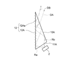
- the shelf light guide element 1A includes an incident surface 11A on which light emitted from the point light source 2 is incident, a reflecting surface 12A that reflects incident light, and an exit surface 13A that emits reflected light.
- the cross section is triangular with three surfaces.
- the reflection surface 12A includes a first reflection surface 12Aa having a diffusion portion 14 that totally reflects the incident light while diffusing the incident light in a predetermined angle range, and the emission surface 13A is formed of the light reflected by the first reflection surface 12Aa. A part of the light is emitted after being refracted, and the exit surface is inclined with respect to the first reflecting surface 12Aa to the extent that the remaining light is totally reflected.
- the point light source 2 is, for example, an LED light source, and is a white LED light source that emits white light by combining a blue LED chip and a phosphor that is excited by light from the LED chip and emits excitation light of a predetermined wavelength.
- the shelf light guide element 1A can be applied as a light guide of an illumination device that emits white light.
- the size of the white LED light source for example, a size of about 0.6 mm ⁇ 1.2 mm is widely used.
- the incident surface 11A of the present embodiment is inclined to such an extent that light incident substantially perpendicular to the incident surface 11A is totally reflected from the first reflecting surface 12Aa. That is, the incident surface 11A is an inclined surface on which light that is totally reflected by the reflecting surface 12 (the reflecting surface 12A and the first reflecting surface 12Aa are collectively referred to as the reflecting surface 12) is incident substantially vertically. With such a configuration, the incident light incident from the incident surface 11A enters the totally reflected light of the reflecting surface 12 at an angle close to vertical, so that the Fresnel reflection on the surface of the incident surface can be reduced and the illuminance is high. It is preferable.
- the inclination angle ⁇ 1 of the incident surface 11A with respect to the reflecting surface 12 is, for example, about 50 to 80 degrees from the parallel position with respect to the reflecting surface 12, preferably about 60 degrees as shown in the figure.
- the inclination angle ⁇ 2 of the emission surface 13A with respect to the reflection surface 12 is preferably, for example, inclined by 1 to 30 degrees from the parallel position with respect to the reflection surface 12, and in this embodiment, is inclined about 15 degrees as shown in the figure. ing.
- the light totally reflected by the exit surface 13A is reflected again by the reflective surface 12 and is refracted and emitted from the exit surface 13A.
- the angle of the light emitted from the exit surface 13A is Since the angle is close to the angle of the light emitted first, it is possible to irradiate bright light in which these lights are synthesized.
- the exit surface 13A since the exit surface 13A is nearly parallel to the reflecting surface 12, the light emitted from the exit surface 13A has a large amount of emitted light in a specific direction that is slightly off the critical angle and is totally reflected by the exit surface 13A. There are many. Since the exit surface 13A is inclined with respect to the reflection surface 12, the light totally reflected by the exit surface 13A has an angle that is smaller by twice the tilt angle of the exit surface 13A due to one reflection at the exit surface 13A. Then, the light is reflected by the reflection surface 12 and emitted from the emission surface 13A. Since the emitted light is emitted when slightly deviating from the critical angle, it can be emitted in a specific direction with high intensity.
- the inclination angle ⁇ 2 of the exit surface 13A with respect to the reflection surface 12 refracts a part of the light from the reflection surface 12, totally reflects the rest, and the totally reflected light is reflected again through the reflection surface 12.
- Any angle may be used so long as it is refracted and emitted when it is incident.
- the number of repetitions of reflection is not limited to two, and may be three or four, so that the inclination angle ⁇ 2 may be inclined by 1 to 30 degrees with respect to the reflecting surface 12 from a parallel position.
- the shelf light guide element 1A is made of a translucent member (PMMA: acrylic) having a refractive index of about 1.5. Therefore, since the total reflection angle is about 42 degrees, if the inclination angle ⁇ 2 is 15 degrees, light having a total reflection angle of 42 to 90 degrees is incident on the exit surface as light of 27 to 75 degrees. Then, light from 27 degrees to less than 42 degrees is emitted. The light of 42 ° to 75 ° totally reflected on the emission surface is reflected on the reflection surface to become an incident angle of 12 ° to 45 °, and almost all of the light is emitted.
- PMMA acrylic
- the light having the total reflection angle remains on the exit surface 13A, but most of the light is emitted with a few round-trip reflections, so the illuminance intensity is large. There is no effect.
- the illuminating device 10A including the shelf light guide element 1A and the point light source 2 is configured to efficiently emit the totally reflected light on the reflecting surface 12 (the reflecting surface 12A and the first reflecting surface 12Aa). Therefore, it is possible to illuminate a specific direction brightly without subjecting the reflecting surface 12 to an expensive process such as a dielectric mirror.
- the light Ra from the point light source 2 toward the reflecting surface 12 is totally reflected by the reflecting surface 12, further totally reflected by the exit surface 13A, and again totally reflected by the reflecting surface 12 and emitted. Injected from the surface 13A in the direction of the arrow DA.
- the light Rb from the point light source 2 toward the exit surface 13A is totally reflected by the exit surface 13A, totally reflected by the reflection surface 12, again totally reflected by the exit surface 13A, and again totally reflected by the reflection surface 12.
- Injected in the direction of the arrow DB from the exit surface 13A That is, light that is reflected back and forth between the exit surface 13A and the reflection surface 12 and deviates from the total reflection angle, that is, light that is substantially reflected by the reflection surface 12 and is close to the emission angle emitted from the exit surface 13A is emitted. It becomes composition.
- the exit surface 13A is emitted obliquely from the exit surface 13A and predetermined from the normal direction of the exit surface 13A.
- High-intensity light is emitted in the vicinity of the A direction that is inclined at an angle (for example, 45 degrees), and light that is emitted in the B direction perpendicular to the reflecting surface 12 is hardly emitted from the reflecting surface 12, so that it is not emitted. It can be configured (controlled) so that only the vicinity of the A direction of the specific direction is irradiated with high intensity.
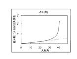
- FIG. 3 shows an incident angle on the exit surface in the medium of a light guide element (shelf plate light guide element) having a refractive index of 1.5 at the D line and a refractive index of only about 0.01 due to chromatic dispersion.
- the angle difference ⁇ degrees (the maximum value of the vertical axis is about 3 °) at the emission angle in different cases is shown.
- the incident angle exceeds 20 degrees in the medium, the angle difference of the exit angle deviates from the linearity, resulting in a large angle difference.
- the incident angle of 20 degrees in the medium is about 30 degrees as the exit angle, it can be understood that the influence of chromatic dispersion becomes large and color unevenness is likely to occur when the exit angle is 30 degrees or more.
- the influence of chromatic dispersion is large at an angle where the incident angle in the medium is several degrees larger than 20 degrees.
- the influence of chromatic dispersion increases at an angle where the incident angle in the medium is several degrees smaller than 20 degrees.
- the shelf light guide element 1A of the present embodiment uses a medium (PMMA) with a refractive index of 1.5, and the incident angle and the emission position on the emission surface 13A via the diffusion portion 14 provided on the first reflection surface 12Aa. Are slightly different from each other and mixed with each other, so that light with reduced color unevenness can be emitted with uniform illuminance.
- PMMA medium with a refractive index of 1.5
- the light R1 emitted from the point light source 2 is diffused within a predetermined angle range by the first reflecting surface 12Aa having the diffusing portion 14, and the light rays L1a having different emission angles from the emission surface 13A. , L1b, and L1c.
- the emission direction of these light beams is refracted and emitted from the emission surface 13A in a predetermined direction, it can be defined in advance in a desired direction.
- the shelf light guide element 1A has an incident surface 11A that is long enough to allow a plurality of point light sources 2 to be juxtaposed at a predetermined interval.
- the lighting device 10A is provided with the long shelf light guide element 1A and the plurality of point light sources 2 and is long in the longitudinal direction.
- the light emitted from the plurality of point-like light sources arranged in parallel is mixed with each other by diffusion at the first reflecting surface 12Aa, and becomes illumination light that is uniform in the longitudinal direction and illuminates a predetermined specific direction. .
- a diffusing portion is arranged on the first reflecting surface immediately before emission to achieve both irradiation in a specific direction and uniformity.
- the incident surface 11A is long enough to allow a plurality of point light sources 2 to be juxtaposed at a predetermined interval, and the reflective surface 12 (12A, 12Aa) and the exit surface having the same size along the longitudinal direction.
- the plurality of point light sources 2 can illuminate widely in the longitudinal direction with high illuminance. Further, since the light from each of the point light sources 2 is diffused, the shelf light guide element that can uniformly irradiate by reducing luminance unevenness of the plurality of point light sources 2 is obtained.
- the diffusion unit 14 is provided in a portion that reflects the reflected light toward the exit surface 13A. With this configuration, it is possible to efficiently reduce color unevenness by diffusing light toward the exit surface 13A into a predetermined angle range. Further, since the light can be guided to the diffusing portion 14 without increasing the luminous flux, the light can be guided while maintaining a high illuminance, and unevenness in brightness and color can be reduced.
- the first reflecting surface 12Aa including the diffusing portion 14 on the reflecting surface 12 is provided only at a position close to the emitting surface 13A, and the unevenness of color on the emitting surface 13A is not increased without unnecessarily increasing the luminous flux and the divergence angle by diffusion.
- the brightness unevenness of the plurality of point light sources 2 and the brightness unevenness of the illumination light beams having different numbers of reflections on the inner surface of the shelf light guide element are reduced.
- the diffusion unit 14 preferably diffuses at a diffusion angle that can suppress the influence of chromatic dispersion. That is, by providing the reflective surface 12 with a rough surface that can be diffused at a predetermined small diffusion angle and small irregularities, or by attaching a diffuse reflection sheet, it is possible to uniformly mix colors and reduce color unevenness effectively. Can do. Therefore, for example, the diffusion portion 14 used here may be formed by roughening the surface of the shelf light guide element 1A, may be formed by printing diffusion dots, a diffusion film or a diffusion reflection plate It is good also as a structure which pastes.
- the LED light source used as the point light source 2 is not limited to a white LED light source using a blue LED and a yellow phosphor, and even a white LED light source using three primary colors of red, blue, and green uses an LED light source other than white. Also good.
- a reflecting member for example, an aluminum cover
- the reflecting member may be an aluminum cover or a member that has been subjected to white reflection processing such as white paint or mirror processing on the cover, or a configuration in which mirror processing is applied to the reflecting surface 12 instead of these members.
- white reflection processing such as white paint or mirror processing on the cover
- mirror processing is applied to the reflecting surface 12 instead of these members.
- the structure which affixed the mirror film may be sufficient.
- an LED light source having high luminance may be used as the LED light source that is the point light source 2, or more LED light sources may be installed.
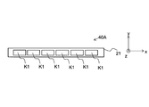
- 13A and 13B show a light source 40A that is an example of a light source 40 in which a plurality of LED light sources K1 that are white light sources are closely arranged. 13A is a top view of the light source 40A, and FIG. 13B is a side view of the light source 40A.
- the LED light source K1 includes a phosphor 42 that converts blue light 43 into yellow light 44 with a predetermined conversion efficiency on a blue LED 41 having a light emission center 41a that emits blue light 43. A part of the blue light 43 is converted into yellow light 44 and the rest is emitted from the LED light source K1, so that the blue light 43 and the yellow light 44 are mixed to form white light.
- the phosphor 42 is formed so as to cover the entire upper part of the blue LED 41. Therefore, when the LED light sources K1 are arranged densely as shown in FIG. 13A, the phosphor 42 portions appear to be arranged continuously even though the light emission centers 41a of the blue LEDs 41 are arranged discretely. Since white light is emitted from the phosphor 42 portion, it looks as if it is a light source having a light emitting surface extending in the direction in which the LED light sources K1 are arranged (X direction in the figure).
- a light source is a linear light source or a linearly long surface light source (XY plane). Therefore, in the present invention, it can be said that a light source having a light emitting surface extending in a direction in which a plurality of the point light sources 2 are arranged may be used instead of the row of the point light sources 2.
- the point light source here refers to a light source in which, for example, the vertical and horizontal sizes of the light emitting surface for emitting light in the horizontal direction are sufficiently small compared to the size of the illumination optical system.
- the length of the point light source in that direction is sufficiently small compared to the length in the direction between the two reflective surfaces ( For example, 1/3) refers to the light source. With this size, the specific direction can be efficiently illuminated.
- the light source 40 having a light emitting surface extending in the direction in which LEDs that are point light sources are arranged include a light source 40B shown in FIGS. 14A and 14B, for example.
- 14A is a top view of the light source 40B
- FIG. 14B is a side view of the light source 40B.
- the light source 40 ⁇ / b> B includes a substrate 21, a plurality of blue LEDs 41 mounted on the substrate 21, and a phosphor 42 that covers the plurality of blue LEDs 41.
- a wiring pattern for supplying power to the blue LED 41 is formed on the substrate 21, one electrode of the blue LED 41 is in contact with the wiring pattern, and the other electrode is wire bonded from the wiring pattern. Has been.
- Blue LED 41 is supplied with electric power and emits blue light 43 from the light emitting surface. As the blue light 43 travels through the phosphor 42, it is converted into yellow light 44 with a conversion efficiency in accordance with the characteristics of the phosphor 42. The light emitted from the phosphor 42 becomes white light by appropriately mixing the blue light 43 and the yellow light 44, and the light source 40B emits white light.
- FIG. 15 shows an example of a lighting device 10A in which the light source 40 (40A, 40B) is mounted on the shelf light guide element 1A.
- the light source 40 (40A, 40B) is mounted on the shelf light guide element 1A.
- Another example corresponding to the light source 40 is a thin-line cold cathode tube.
- a modification of the illuminating device 10A provided with such a light source 50 is shown in FIG.
- a light source 50 made of a cold cathode tube is mounted on the shelf light guide element 1A.
- the shelf light guide element 1A includes the first reflecting surface 12Aa that guides the incident light to the exit surface 13A while diffusing the incident light in a predetermined angle range, and the predetermined direction from the exit surface 13A. Since the light is refracted and emitted, the light distribution of the point light source 2 is controlled so that the light guide element for shelf plates can be illuminated efficiently and uniformly in a desired specific direction.
- the shelf-plate light guide element 1B faces the first reflecting surface 12Ba substantially in parallel and transmits light from the first reflecting surface 12Ba. It is an example which has 2nd reflective surface 12Bb which receives and reflects toward 1st reflective surface 12Ba.
- the diffusing portion 14 provided on the first reflecting surface 12Ba is provided near the exit surface 13B so that the luminous flux and the divergence angle are not increased unnecessarily by diffusion. Since the luminous flux and the divergence angle are not increased, light can be efficiently guided using total reflection without increasing the size.
- a reflection member similar to that described above is provided on the back surfaces of the first reflection surface 12Ba and the second reflection surface 12Bb, and all light that is not totally reflected by the respective reflection surfaces is re-entered into the shelf light guide element. I am doing so.
- the second reflecting surface 12Bb is substantially parallel to the first reflecting surface 12Ba, most of the light reflected by the second reflecting surface 12Bb is guided to the first reflecting surface 12Ba and then guided to the exit surface 13B to be emitted. . Further, the light that is reflected directly from the incident surface 11B or reflected by the second reflecting surface 12Bb and guided to the exit surface 13B makes the exit surface 13B at an angle close to parallel to the first reflecting surface 12Ba and the second reflecting surface 12Bb. By inclining, the number of times of total reflection at the exit surface 13B and reflection toward the exit surface 13B at the first reflective surface 12Ba is repeated once (light Rc shown by a dotted line in the drawing) or a plurality of times. The light exits sequentially from the exit surface 13B that deviates from the total reflection angle.
- the exit surface 13B is ejected obliquely from the exit surface 13B, and a predetermined angle from the normal of the exit surface 13B.
- High-intensity light is emitted in the vicinity of the direction of arrow A in the drawing (for example, 45 degrees), and the light emitted in the direction of arrow B in the drawing perpendicular to the first reflection surface 12Ba is emitted from the first reflection surface 12Ba. Since it is hardly guided, it is not emitted, and it can be controlled so that only the vicinity of the A direction in a specific direction is irradiated with high intensity.
- light having a different number of reflections between the second reflection surface 12Bb and the first reflection surface 12Ba is mixed with each other because the incident angle and the emission position on the emission surface 13B are slightly different depending on the diffusion portion 14 on the first reflection surface 12Ba. And can be injected uniformly without large diffusion.
- the light guide element for a shelf plate can be illuminated efficiently and uniformly in a desired specific direction by controlling the light distribution of the point light source.
- the illuminating device 10B provided with the shelf light guide element 1B and the point light source 2 can control the light distribution of the point light source 2 to illuminate efficiently and uniformly in a desired specific direction. .
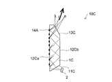
- the shelf light guide element 1C of the third embodiment shown in FIG. 5 is a first reflection in which a diffusion portion is provided on the entire surface in place of the first reflection surface 12Ba provided in the shelf light guide element 1B of the second embodiment.
- An example provided with surface 12Ca is shown.
- the diffusing portion 14A is formed of diffusing dots by printing.
- the diffusing portion 14A composed of diffusing dots can be controlled to a smaller diffusing angle, the divergence angle from the light beam and the exit surface is not increased unnecessarily, and a specific direction (for example, the arrow direction shown in the figure). Can be injected.
- a specific direction for example, the arrow direction shown in the figure.
- diffusion dots are provided on the side close to the incident surface 11C, the emitted light may have a slightly larger divergence angle.
- irradiation control in a specific direction can be performed by refraction at the emission surface 13C. Is possible.
- the incident surface 11C is inclined like the incident surface 11B of the shelf light guide element 1B of the second embodiment, even if the inclined surface is similar to the incident surface 11A of the first embodiment as shown in the figure. Instead, it may be a surface in a direction orthogonal to the first reflecting surface.
- this shelf light guide element 1C is a shelf light guide element that guides all incident light to the exit surface 13C while diffusing the incident light in a predetermined angle range and emits the light from the exit surface 13C in a specific direction. Since there is no change, light distribution control of the light from the point light source provides a shelf light guide element that can illuminate efficiently and uniformly in a desired specific direction.
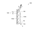
- the shelf light guide element 1D of the fourth embodiment shown in FIG. 6 is different from the shelf light guide element 1C of the third embodiment in that it is diffusely reflected using an aluminum cover 15.
- the configuration is the same, and includes an incident surface 11D on which the light from the point light source 2 is incident, a first reflecting surface 12Da, a second reflecting surface 12Db, and an exit surface 13D.
- the aluminum cover 15 includes a reflecting surface 15a having a diffuse reflecting function, and the reflecting surface 15a diffuses and reflects light that is not totally reflected by the first reflecting surface 12Da, and then enters the shelf light guide element 1D again. Let That is, the aluminum cover 15 provided with the reflection surface 15a having the diffuse reflection function forms the diffusion portion 14B.
- the shelf light guide element 1D of the fourth embodiment is still a shelf light guide element that emits all incident light from the exit surface while diffusing the incident light in a predetermined angle range. Therefore, the light guide element for a shelf plate that can control the light distribution of the point light source to illuminate efficiently and uniformly in a desired specific direction.
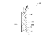
- the shelf light guide element 1E according to the fifth embodiment shown in FIG. 7 is a diffusion part made of diffusion dots on the second reflecting surface, instead of the diffusion part 14A provided in the shelf light guide element 1C according to the third embodiment.
- the other configuration is the same except that 14C is provided. That is, it includes an incident surface 11E on which the light from the point light source 2 is incident, a first reflective surface 12Ea, a second reflective surface 12Eb, and an exit surface 13E.
- the second reflecting surface 12Eb includes the diffusing portion 14C, the light diffused by the diffusing portion 14C at a predetermined small angle is reflected toward the first reflecting surface 12Ea, and is emitted from the first reflecting surface 12Ea to the exit surface 13E. Led to.
- the shelf light guide element 1E is a shelf light guide element that emits all incident light from the exit surface 13E while diffusing the incident light in a predetermined angle range.
- the light distribution element for the shelf plate can be illuminated efficiently and uniformly in a desired specific direction by controlling the light distribution.
- both the lighting device 10C provided with the shelf light guide element 1C and the point light source 2 and the illumination device 10D provided with the shelf light guide element 1D and the point light source 2 are used as the shelf light guide element 1E.
- the illumination device 10E provided with the point light source 2 can also illuminate efficiently and uniformly in a desired specific direction by controlling the light distribution of the light from the point light source 2, respectively.
- This embodiment includes a first shelf light guide element 1Aa and a second shelf light guide element 1Ab, and transmits light from one point light source 2 via a pair of shelf light guide elements. An example in which light is guided in two different directions is shown.
- the shelf light guide element 1F is a configuration in which the first shelf light guide element 1Aa and the second shelf light guide element 1Ab are combined vertically.
- the illuminating device 10F provided with the shelf light guide element 1F has a configuration in which the point light sources 2 are arranged at the abutting portions of the pair of shelf light guide elements.
- the incident surface 11Aa of the first shelf light guide element 1Aa and the incident surface 11Ab of the second shelf light guide element 1Ab intersect at a predetermined angle.
- the light received from the point light source 2 is branched in two different directions.
- since light incident from each incident surface is reflected back and forth between the reflecting surface and the exit surface, and light deviating from the total reflection angle is emitted, it is possible to illuminate two different specific directions with high illuminance. .
- the shelf light guide element 1F including the first shelf light guide element 1Aa and the second shelf light guide element 1Ab transmits light emitted from one LED light source in two different directions. Since the light can be guided and the two different directions can be illuminated brightly and efficiently uniformly, the illumination device 10F receives light from the plurality of point light sources 2 and can illuminate widely in the longitudinal direction with high illuminance. Further, since the light from each point light source 2 is diffused and emitted in a predetermined direction, two different specific directions can be illuminated uniformly.
- shelf light guide elements 1B to 1E may be combined in place of the shelf light guide element 1A. Can be used in appropriate combination. Furthermore, it replaces with a pair of two, and can also use the integrated light guide element for shelf boards of the shape which combined the pair of two.
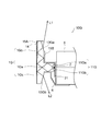
- the shelf light guide element 1G of the seventh embodiment shown in FIG. 9 has a T-shaped cross section integrally including an incident portion 1Ga having an incident surface 11G, a first light guide portion 1Gb, and a second light guide portion 1Gc. It is a light guide element for shelf boards, Comprising: The light which the point light source 2 inject
- the shelf light guide element 1G mounted on the front end of the shelf plate 5 using the attachment member 6 is a point light source 2 mounted on the front end of the shelf plate 5 (a chip-type light source in which an LED light source is mounted on the substrate 21).
- the light from the light source is split into a light beam L1 emitted in a specific direction on the upper side of the shelf board 5 and a light beam L2 emitted in a specific direction on the lower side of the shelf board 5 and emitted.
- the illumination device 10G in which the point light source 2 and the shelf light guide element 1G are disposed at the tip of the shelf plate 5 can simultaneously illuminate the specific directions above and below the shelf plate 5. Therefore, by using the lighting device 10G having a long shape including a plurality of point light sources 2 along the shelf 5 of the showcase, it becomes possible to efficiently and uniformly illuminate products displayed in the showcase. .
- 15A and 15B are aluminum covers having a diffuse reflection function, for example, and reflect toward the inside of the shelf light guide element 1G without emitting light except in a desired specific direction. And a function of diffusing in a predetermined angle range when reflecting.
- the diffuser 14 is provided near the exit surface of the cover 15A, and the reflected light diffused in a predetermined angle range is reflected toward the upper exit surface 13Ga, thereby suppressing color unevenness and illumination unevenness. It becomes possible.
- the light emitted from the point light source 2 and incident on the intersecting incident surfaces 11Ga and 11Gb is all emitted toward the first light guide 1Gb and emitted from the emission surface 13Ga, and the light directed toward the second light guide 1Gc All are ejected from the exit surface 13Gb.
- the lighting device 10G using the shelf light guide element 1G that branches and guides the light emitted from the point light source 2 in two different directions simultaneously illuminates a specific direction above and below the shelf. Therefore, the lighting device can efficiently and uniformly illuminate products displayed in the showcase.
- the eighth embodiment shown in FIG. 10 shows an example in which a branching portion for branching the light emitted from the point light source 2 is provided on the back side of the shelf light guide element facing the point light source 2.
- the shelf light guide element 1H of the eighth embodiment has a T-shaped cross section because it directly receives the light emitted from the point light source 2 and branches in two different directions at a branching portion 11H provided on the back surface side. There is no need, and a plate shape as shown in the figure may be used.
- the branch portion 11H has a V shape in which the first branch surface 11Ha and the second branch surface 11Hb intersect at a predetermined angle, and the light reflected by the first branch surface 11Ha is first emitted through the first light guide portion 1Hb.
- the light guided to the surface 13Ha and reflected by the second branch surface 11Hb is guided to the second exit surface 13Hb via the second light guide 1Hc.
- the first exit surface 13Ha is inclined at a predetermined angle (for example, 10 to 30 degrees) with respect to the first reflective surface 12H, and emits a light beam L1 directed in a specific direction, like the exit surfaces 13A and 13B described above.
- the second emission surface 13Hb may be provided on a plate-like lower surface.
- the light beam L2 and the shelf plate that are emitted toward the shelf plate on the lower side of the shelf light guide element 1H.
- the light beam L3 emitted in a direction away from the light source, a wide range below the shelf light guide element 1H is illuminated.
- the lighting device 10H having a configuration in which the substrate 21 on which the point light source 2 is mounted, the shelf light guide element 1H, and the reflection member 15C are attached via the holder 7 attached to the tip of the shelf 5A and the stay 7A.
- Illumination light (L1) directed obliquely upward of the shelf plate 5A to which the plate light guide element 1H is attached and illumination light (L2 + L3) that illuminates a wide range below the shelf plate 5A are emitted.
- the reflection plate 12Hb may be attached to a predetermined portion of the shelf light guide element 1H including the surface facing the substrate 21.
- the object surface of the product M placed on the shelf board 5A is effectively illuminated by the illumination light directed obliquely upward, and the shelf board 5A is illuminated by the illumination light that illuminates the wide range below the shelf board 5A.
- the upper part of the product placed on the lower shelf board is effectively illuminated. That is, by providing the lighting device 10H according to this embodiment on a plurality of shelf boards, it is possible to illuminate an object on the shelf board from above and below.
- the illuminating devices 10A to 10H provided with the shelf light guide elements 1A to 1H according to the present embodiment described above are diffused so as to reduce color unevenness and luminance unevenness and led to the exit surface, and the total reflection angle from the exit surface Since the light deviated from the light is refracted and emitted in the oblique direction, the light distribution is controlled in a predetermined specific direction, and the oblique specific direction can be illuminated efficiently and uniformly.
- the shelf light guide elements 1 (1A to 1H) are attached to the shelf plate 5B on which tall products M1 such as milk packs and juice packs are placed, and then directed in a specific direction.
- An illuminating device that uniformly emits the light beams L1a, L1b, and L1c can be realized.
- the conventional illumination device since it is diffused on the exit surface, it is greatly scattered on the exit surface, and it is difficult to control the exit in a specific direction, and luminance unevenness in the illumination area is also large. Moreover, if it is not diffused, the illumination uniformity is impaired due to color unevenness due to color dispersion on the exit surface, luminance unevenness due to emitted light having different number of reflections, and brightness unevenness of a plurality of point light sources.
- the shelf light guide element and the illumination device can illuminate a desired specific direction brightly, efficiently and uniformly.
- a chip-type LED light source as a point light source
- other point light sources may be used, for example, a lens-attached or bullet-type LED light source may be used.
- the light guide element for shelves it is possible to effectively illuminate a specific direction at a position different from the point light source.
- light is emitted in an oblique direction from an exit surface that is nearly parallel to the reflective surface, light is emitted with high intensity in a specific direction, and color unevenness due to color dispersion on the exit surface is reduced through a diffusion unit provided in the first reflective surface. Irradiation with a uniform color is possible.
- the shelf since the light reflected with high efficiency using the total reflection light is refracted from the exit surface and emitted, the shelf that can control the light distribution of the point light source to illuminate efficiently and uniformly in the desired specific direction.
- a light guide element for a plate can be obtained.
- the lighting device it is possible to obtain a lighting device capable of illuminating efficiently and uniformly in a desired specific direction by controlling the light distribution of the point light source.
- the light guide element for a shelf and the lighting device according to the present invention are used as a lighting device for illuminating a tall product placed on the shelf of a multistage showcase having a plurality of shelf plates above and below. It can be suitably applied.
- 1A to 1H Shelf light guide element 2 Point light source (light source, LED light source) 5, 5A, 5B Shelf plate 10A to 10H Illuminating device 11, 11A to 11H Incident surface 12 Reflecting surface 12Aa to 12Ha First reflecting surface 12Ab to 12Hb Second reflecting surface 13A to 13H Ejecting surface 14, 14A to 14C Diffusion unit
Landscapes
- Physics & Mathematics (AREA)
- General Physics & Mathematics (AREA)
- Optics & Photonics (AREA)
- Planar Illumination Modules (AREA)
- Arrangement Of Elements, Cooling, Sealing, Or The Like Of Lighting Devices (AREA)
Abstract
光源の光を配光制御して所望の特定方向に明るく効率よく均一に照明可能な棚板用導光素子および照明装置を得るために、入射した光を所定角度範囲に拡散しながら全反射する拡散部14を有する第一反射面12Aaを備えた反射面を有し、第一反射面により反射された光の一部を屈折させて射出し、残りの光を全反射する程度に第一反射面に対して傾斜した射出面13Aから射出する棚板用導光素子1A~1Hとし、この棚板用導光素子1A~1Hと光源(点状光源2)と、を備えた照明装置10A~10Hとした。
Description
本発明は、棚板用導光素子および照明装置に関し、例えば、ショーケース等に配設され、ショーケースの棚板に陳列される商品の照明に好適な照明装置、およびそれに用いる棚板用導光素子に関する。
従来から、ショーケースに配設され、ショーケースに陳列された商品を照明するものとして、蛍光灯が広く用いられている。蛍光灯は、一般に電気エネルギーを可視放射、赤外放射、紫外放射に変換し、可視光線を放射することで、照明として用いるものである。その際、熱損失が生じるため、蛍光灯自体のみならず、当該蛍光灯による輻射熱によって、陳列された商品が加熱されるという問題があり、ショーケース用の照明装置の光源としては、必ずしも好ましいものとはいえない。
近年、発光効率の向上や発光量の増加と共に、寿命が長く消費電力が小さくて、環境にやさしいとされるLED(Light Emitting Diode:発光ダイオード)を用いた照明装置が実用化されつつある。また、青色LEDチップが開発されて以来、この青色LEDチップと、このLEDチップからの光に励起されて所定波長の励起光を発光する蛍光体と、を組み合わせて白色発光する白色LED光源や、青色LEDチップと緑色LEDチップと赤色LEDチップとの三原色のLEDチップを用いて白色光を合成する白色LED光源が開発されている。
そのために、照明装置として、この白色LED光源を配設したLED照明装置を用いると、消費電力削減や製品寿命の長寿命化を図ることができて好ましい。特に、ショーケースなどの陳列棚の照明装置として、消費電力が小さく、発熱も小さいLED光源を用いることが模索されており、例えば、陳列棚の前端部に立設される商品落下防止用のガードの下側にLED照明装置を配設し、棚上の商品に向けて照射する構成のショーケースが既に提案されている(例えば、特許文献1参照)。
また、陳列棚の先端に設けられたプライスレール内にLED光源を配設して、光源の手前側に設けた反射板を介して棚の上下を照射するとしたショーケースが既に提案されている(例えば、特許文献2参照)。
ところで、特許文献1に記載されたショーケースでは、ガードを透光性の板材製として、このガードを通してLED光源から出射される光を棚上の商品に向けて照射しているので、射出光が大きく散乱してしまい暗くなってしまい、均一に効率よく照明することができない問題が生じる。
また、特許文献2に記載されたショーケースのように、一つのLED光源で棚の上下を同時に照明する構成では、少ない光源数で効率よく照明できるため、ある程度の照度を確保しながら光源の部品点数を抑えることができコスト削減図ることができる。しかし、棚の手前側に設置した反射板からの反射光により、商品の照明を行っているため、光源から射出された光の向きを変えて商品を照明しているのみであり、積極的に照明光の指向性制御や配光制御を行うことができない。
従って、牛乳パックや飲料ボトルなど背の高い商品を棚に陳列した際には、上側からの照明光も下側からの照明光も、綺麗な商標やロゴが印刷された商品の中程当りに届き難くなり、消費者の視覚に訴えて購買意欲を喚起させる効果が小さくなる虞が生じる。
また、低コスト化と意匠性を向上させるためには、光源から出射される光を所定範囲に拡散し所望の方向に効率よく導光可能な棚板用導光素子を用いたコンパクトな構成の照明装置を用いることが好ましい。
本発明は、上記の事情に鑑みてなされたものであって、光源の光を配光制御して所望の特定方向に明るく効率よく均一に照明可能な棚板用導光素子および照明装置を提供することを目的とする。
上記目的を達成するために本発明は、光源から出射される光が入射する入射面と、入射した光を反射する反射面と、反射された光を射出する射出面を備えた導光素子であって、前記反射面は、入射した光を全反射する第一反射面を備え、前記射出面は、前記第一反射面により全反射された光の一部を屈折させて射出し、残りの光を全反射するように前記第一反射面に対して傾斜した射出面で、射出光の最大強度光は射出面法線方向に対して傾斜した方向に射出し、前記第一反射面は入射した光を所定角度範囲に拡散しながら全反射する拡散部を備えると共に、棚板の前端部に沿って配置され、棚板の少なくとも上下の一方を照明する棚板用導光素子としたことを特徴としている。
上記の構成によると、棚板の前端部から、光源とは別の位置の特定方向を効果的に照明することが可能となる。また、反射面に平行に近い射出面から斜め方向に射出するので、特定方向に高強度で光を照射し、且つ、第一反射面に備える拡散部を介して射出面色分散による色ムラを軽減して均一な色合いで照射可能となる。さらに、全反射光を利用して高効率反射した光を射出面から屈折させて射出するので、点状光源の光を配光制御して所望の特定方向に明るく効率よく均一に照明可能な棚板用導光素子を得ることができる。
また本発明は上記構成の棚板用導光素子において、前記拡散部は、色ムラの発生を抑制可能な拡散角度で拡散することを特徴としている。この構成によると、反射面に、所定の小さな拡散角度に拡散可能な粗面や小さな凹凸を設けたり、拡散反射シートを貼付したりすることで、均一に混色して色ムラを効果的に軽減することができる。
また本発明は上記構成の棚板用導光素子において、前記射出光の最大強度光は、射出面法線方向に対して30度より大きな角度傾斜した方向に射出することを特徴としている。この構成によると、射出面から30度以上傾斜した特定方向に高強度で光を射出することができる。
また本発明は上記構成の棚板用導光素子において、前記射出面は、前記第一反射面に対して平行位置から1~30度傾斜していることを特徴としている。この構成によると、射出面で全反射する光が第一反射面で再び反射されて射出面から射出する光の角度が、最初に射出される光の角度に近い角度となるので、合成された明るい光を照射することができる。
また本発明は上記構成の棚板用導光素子において、前記入射面は、この入射面に対して略垂直に入射する光が前記第一反射面から全反射されるように傾斜していることを特徴としている。この構成によると、第一反射面で全反射する光を入射面に対して略垂直に入射させるので、入射面表面でのフレネル反射を減らすことができて高照度となる。
また本発明は上記構成の棚板用導光素子において、前記入射面は、前記第一反射面に対して平行位置から50~80度傾斜していることを特徴としている。この構成によると、入射面は第一反射面の全反射光を垂直に入射するので、表面でのフレネル反射を減らして高照度となる。
また本発明は上記構成の棚板用導光素子において、前記入射面は前記光源を所定間隔で複数並設可能な程度に長寸とされ、この長手方向に沿って同寸の反射面と射出面を有することを特徴としている。この構成によると、複数の光源により長手方向に広く高照度に照明可能で、且つ、それぞれの光源からの光をそれぞれ拡散しているので複数の光源の輝度ムラを軽減して均一に照射可能な棚板用導光素子となる。
また本発明は上記構成の棚板用導光素子において、前記反射面は、前記第一反射面に略平行に対向し、前記第一反射面から光を受けて前記第一反射面に向けて反射する第二反射面を有することを特徴としている。この構成によると、光源から離れた位置を照射可能となる。また、第二反射面は第一反射面に対して略平行なので、第一反射面で全反射した光は第二反射面でも全反射して高効率な反射となる。また、光源から射出面までの光路長が長くなるので、並設する光源の間隔を長くすることができ、光源の設置数量を減らすことができる。
また本発明は上記構成の棚板用導光素子において、前記拡散部は、前記射出面に向けて反射光を反射する部位に設けられていることを特徴としている。この構成によると、射出面に向かう光を拡散しているので、色ムラを効率よく軽減可能となる。また、拡散部までは、光束を大きくしないで導光できるので、高照度を維持して導光可能となり、輝度ムラと色ムラを軽減することができる。
また本発明は、光源と、該光源から出射される光が入射する入射面と、入射した光を反射する反射面と、反射された光を射出する射出面を備えた導光素子と、を備えた照明装置であって、前記導光素子として請求項1から9のいずれかに記載された棚板用導光素子を備えたことを特徴としている。
上記の構成によると、光源の光を配光制御して所望の特定方向に明るく効率よく均一に照明可能な照明装置を得ることができる。
また本発明は上記構成の照明装置において、前記棚板用導光素子は、第一および第二導光素子を有する一対二個の棚板用導光素子からなり、一つの前記光源が発する光を異なる二方向に導光することを特徴としている。この構成によると、異なる二方向を明るく効率よく均一に照明可能な特定方向とすることができ、一つの光源を用いて異なる二つの特定方向を均一に照明可能となる。
また本発明は上記構成の照明装置において、前記棚板用導光素子は、前記光源が発する光を異なる二方向に分岐する分岐部を備えた一体型であって、一つの前記光源が発する光を異なる二方向に導光する第一および第二導光部を有することを特徴としている。この構成によると、簡単で小型な構造の棚板用導光素子を用いて、低コストで異なる二つの特定方向を均一に照明可能な照明装置を得ることができる。
また本発明は上記構成の照明装置において、前記光源は点状光源であることを特徴としている。光源を点状光源とすることで、特定方向に高強度で光を照射することが可能となる。
また本発明は上記構成の照明装置において、前記点状光源はLED光源であることを特徴としている。光源をLED光源とすることで、低コストで高い光強度の照明装置を提供することが可能となる。
また本発明は上記構成の照明装置において、前記光源を所定間隔で複数並設し、この並設する長手方向に沿って長寸の入射面と反射面と射出面を有し、棚板の前端部に沿って設置することを特徴としている。この構成によると、例えば、棚板の上下を同時に照明することができ、ショーケースの棚板に陳列する商品を効率よく均一に照明可能な照明装置となる。
本発明によれば、入射した光を所定角度範囲に拡散しながら全反射する拡散部を有する第一反射面を備えた反射面とし、第一反射面により反射された光の一部を屈折させて射出し、残りの光を全反射する程度に第一反射面に対して傾斜した射出面から射出する棚板用導光素子としているので、光源の光を配光制御して所望の特定方向に明るく効率よく均一に照明可能な棚板用導光素子を得ることができる。また、この棚板用導光素子を用いて、光源の光を配光制御して所望の特定方向に明るく効率よく均一に照明可能な照明装置を得ることができる。
以下に本発明の実施形態を図面を参照して説明する。また、同一構成部材については同一の符号を用い、詳細な説明は適宜省略する。
〈第一実施形態〉
まず、図1A、図1B、図2、図3を用いて本発明に係る棚板用導光素子の第一実施形態、および、第一実施形態の棚板用導光素子1Aを備えた照明装置10Aについて説明する。なお、以下の説明においては、説明の簡素化のために、光源は点状光源であるとして説明するが、点状光源以外の光源、例えば、面状光源や線状光源を用いてもよい。図1Aに示すように、照明装置10Aは棚板用導光素子1Aと点状光源2を備えた構成とされる。この棚板用導光素子1Aは、点状光源2から出射される光が入射する入射面11Aと、入射した光を反射する反射面12Aと、反射された光を射出する射出面13Aとの3面を備えた断面三角形状とされる。
まず、図1A、図1B、図2、図3を用いて本発明に係る棚板用導光素子の第一実施形態、および、第一実施形態の棚板用導光素子1Aを備えた照明装置10Aについて説明する。なお、以下の説明においては、説明の簡素化のために、光源は点状光源であるとして説明するが、点状光源以外の光源、例えば、面状光源や線状光源を用いてもよい。図1Aに示すように、照明装置10Aは棚板用導光素子1Aと点状光源2を備えた構成とされる。この棚板用導光素子1Aは、点状光源2から出射される光が入射する入射面11Aと、入射した光を反射する反射面12Aと、反射された光を射出する射出面13Aとの3面を備えた断面三角形状とされる。
また、反射面12Aは、入射した光を所定角度範囲に拡散しながら全反射する拡散部14を有する第一反射面12Aaを備え、射出面13Aは、第一反射面12Aaにより反射された光の一部を屈折させて射出し、残りの光を全反射する程度に第一反射面12Aaに対して傾斜した射出面とされる。
点状光源2は、例えばLED光源であって、青色LEDチップと、このLEDチップからの光に励起されて所定波長の励起光を発光する蛍光体と、を組み合わせて白色発光する白色LED光源を用いることで、この棚板用導光素子1Aを白色発光する照明装置の導光体として適用することができる。かかる白色LED光源の大きさとしては、例えば、0.6mm×1.2mm程度のものが汎用されている。
また、本実施形態の入射面11Aは、この入射面11Aに対して略垂直に入射する光が第一反射面12Aaから全反射される程度に傾斜している。すなわち、入射面11Aは、反射面12(反射面12Aと第一反射面12Aaを総称して反射面12として説明する)が全反射する光を略垂直に入射させる傾斜面とされている。このような構成であれば、入射面11Aから入射する入射光は反射面12の全反射光を垂直に近い角度で入射するので、入射面表面でのフレネル反射を減らすことができ高照度となって好ましい。
入射面11Aの反射面12に対する傾斜角度α1は、例えば、反射面12に対して平行位置から50~80度程度、好ましくは、図に示すように約60度傾斜している。このような構成であれば、入射面11Aに垂直に入射した光を反射面12で全反射させることができ、フレネル反射を抑制可能となる。すなわち、反射面12の全反射光を垂直に入射するので、表面でのフレネル反射を減らして高効率に導光可能となる。
射出面13Aの反射面12に対する傾斜角度α2は、例えば、反射面12に対して平行位置から1~30度傾斜していることが好ましく、本実施形態では図に示すように約15度傾斜している。このような構成であれば、射出面13Aで全反射した光は、反射面12で再び反射されて射出面13Aから屈折射出する、また、この際に、射出面13Aから射出する光の角度は、最初に射出される光の角度に近い角度となるので、これらの光が合成された明るい光を照射することができる。
つまり、射出面13Aが反射面12に平行に近いので、射出面13Aで射出される光は臨界角を少し外れて射出された特定方向に射出光が多く、射出面13Aで全反射される光も多い。射出面13Aで全反射する光は、射出面13Aが反射面12に対して傾斜しているので、射出面13Aでの1回の反射により射出面13Aの傾斜角度の二倍だけ小さい角度となって反射面12にて反射され、射出面13Aから射出する。この射出される光は臨界角を少し外れたときに射出するので、特定方向に高強度にて射出することができる。
すなわち、射出面13Aの反射面12に対する傾斜角度α2は、反射面12からの光の一部を屈折出射し、残りを全反射させ、全反射した光が再び反射面12を介して反射して入射したときに、屈折出射する程度の角度であればよい。また、反射の繰り返し回数は2回に限定されず、3回でも4回でも良いので、傾斜角度α2は反射面12に対して平行位置から1~30度傾斜していてもよい。
本実施形態では、棚板用導光素子1Aを、屈折率が約1.5の透光性部材(PMMA:アクリル)製としている。そのために、全反射角は約42度となるので、傾斜角度α2が15度であれば、全反射角42度から90度の光が、射出面に27度から75度の光となって入射し、27度から42度未満の光が射出する。射出面で全反射する42度から75度の光は、反射面で反射されて入射角12度から45度となり、略全ての光が射出する。なお、反射面12(第一反射面12Aa)で拡散するので、射出面13Aで全反射角となる光は残るが、数回の少ない往復反射で大部分の光が射出するので照度強度に大きな影響はない。
このように、棚板用導光素子1Aと点状光源2を備える照明装置10Aは、反射面12(反射面12Aと第一反射面12Aa)での全反射光を効率よく射出する構成としているので、反射面12に誘電体ミラーのような高価な処理を施すことなく、特定方向を明るく照明することができる。
例えば、図2に示すように、点状光源2から反射面12に向かう光Raは、反射面12で全反射し、射出面13Aでさらに全反射し、再度反射面12で全反射して射出面13Aから矢印DA方向に射出する。
また、点状光源2から射出面13Aに向かう光Rbは、射出面13Aで全反射し、反射面12で全反射し、再度射出面13Aで全反射し、再度反射面12で全反射した後、射出面13Aから矢印DB方向に射出する。つまり、射出面13Aと反射面12との間で往復反射して全反射角から外れた光、すなわち、反射面12で全反射されて射出面13Aで射出される射出角に近い光が射出する構成となる。
上記したように、射出面13Aの傾斜角度α2を反射面12に近い角度(例えば、15度)に設定することで、射出面13Aより斜め方向に射出して射出面13Aの法線方向から所定角度傾斜(例えば、45度)したA方向付近には高強度の光が射出し、反射面12に垂直なB方向に射出する光は反射面12から殆んど導かれないので射出せず、特定方向のA方向付近のみを高強度に照射するように構成する(制御する)ことができる。
射出面13Aの傾斜角が反射面12に平行に近いほど反射面12で全反射する光が射出面13Aでも全反射する光が多くなり射出面13Aに平行な方向に射出光が偏り、より限られた特定方向のみを高強度に照明できる。
このとき、図3に示すように、射出面に対する入射角が20度より大きい(射出角が30度よりも大きいことに相当)と色分散による影響が大きくなる。すなわち、色ムラが発生する虞が生じる。しかし、第一反射面での拡散部によって射出面への入射角度や射出位置が少しずつ異なるので、互いに混ぜ合わされて大きく拡散せずに色ムラの発生を抑制可能となって、色ムラが軽減された照明光を均一に射出することができる。
図3は、D線での屈折率が1.5の導光素子(棚板用導光素子)における媒質内での射出面への入射角と、色分散により屈折率が約0.01だけ異なる場合の射出角における角度差Δθ度(縦軸の最大値が3°程度である)を示している。この図から判るように、媒質内で20度を超える入射角では射出角の角度差が線形から外れ、大きな角度差が生じる。また、媒質内での入射角20度は射出角で約30度となるので、射出角30度以上において色分散の影響が大きくなって、色ムラが生じやすくなることが判る。
なお、棚板用導光素子に屈折率が1.5より低い材料を用いた場合は、媒質内での入射角が20度より数度だけ大きい角度にて色分散による影響が大きく、屈折率が1.5より高い材料を用いた場合は、媒質内での入射角が20度より数度小さい角度にて色分散の影響が大きくなる。
本実施形態の棚板用導光素子1Aは屈折率1.5の媒質(PMMA)を用いて、第一反射面12Aaに設ける拡散部14を介して、射出面13Aへの入射角度や射出位置が少しずつ異ならせて互いに混ぜ合わせているので、色ムラが軽減された光を均一な照度で射出することができる。
例えば、図1Aに示すように、点状光源2から射出された光R1は、拡散部14を有する第一反射面12Aaにより所定角度範囲に拡散され、射出面13Aからそれぞれ射出角度が異なる光線L1a、L1b、L1cとして射出される。また、これらの光線の射出方向は、射出面13Aから所定方向に屈折して射出するので、所望の方向に予め規定しておくことができる。
そのために、棚板用導光素子1Aが図1Bに示すように、点状光源2を所定間隔で複数並設可能な程度に長寸とされる入射面11Aと、この長手方向に沿って同寸の反射面と射出面13Aを有する長尺部材からなる場合は、この長尺な棚板用導光素子1Aと複数の点状光源2を備えて長手方向に長い照明装置10Aであっても、複数並設された点状光源から出射される光は、第一反射面12Aaでの拡散によって互いに混ぜ合わされて、長手方向にも均一な、また、所定の特定方向を照明する照明光となる。
従来のように、射出面に拡散手段を配設する構成では、照明光の発散角が大きくなってしまい所望される特定方向を高強度に照射することができない。本実施形態では、射出する直前の第一反射面に拡散部を配置して特定方向への照射と均一性を両立している。
上記したように、入射面11Aは、点状光源2を所定間隔で複数並設可能な程度に長寸とされ、この長手方向に沿って同寸の反射面12(12A、12Aa)と射出面13Aを有する構成とすることで、複数の点状光源2により長手方向に広く高照度に照明可能となる。また、それぞれの点状光源2からの光をそれぞれ拡散しているので複数の点状光源2の輝度ムラを軽減して均一に照射可能な棚板用導光素子となる。
拡散部14は、射出面13Aに向けて反射光を反射する部位に設けることが好ましい。この構成であれば、射出面13Aに向かう光を所定角度範囲に拡散して、色ムラを効率よく軽減可能となる。また、拡散部14までは、光束を大きくしないで導光できるので、高照度を維持して導光可能となり、輝度ムラと色ムラを軽減することができる。
すなわち、反射面12における拡散部14を備える第一反射面12Aaは射出面13Aに近い位置にのみ設けて、拡散により光束と発散角をむやみに大きくせずに、射出面13Aでの色ムラや、複数の点状光源2の輝度ムラ、棚板用導光素子内面での反射回数の異なる照明光束の輝度ムラを軽減している。
この拡散部14は、色分散の影響を抑制可能な程度の拡散角度で拡散することが好ましい。すなわち、反射面12に、所定の小さな拡散角度に拡散可能な粗面や小さな凹凸を設けたり、拡散反射シートを貼付したりすることで、均一に混色して色ムラを効果的に軽減することができる。そのために、ここで用いる拡散部14は、例えば、棚板用導光素子1Aの表面を粗面加工して形成してもよく、拡散ドットを印刷形成してもよく、拡散フィルムや拡散反射板を貼り付ける構成としてもよい。
また、点状光源2として使用するLED光源は、青色LEDと黄色蛍光体を用いた白色LED光源に限定されず、赤青緑の三原色LEDによる白色LED光源でも、白色以外のLED光源を用いても良い。
また、反射面12で全反射しない光は、反射面12の背面に反射部材(例えば、アルミ製カバー)を配置して、この反射部材により反射された光が棚板用導光素子に再入射するように構成することが好ましい。この反射部材は、アルミ製カバーや、カバーに白色塗料などの白色反射処理やミラー処理を施した部材を用いてもよいし、これらの部材に替えて反射面12にミラー処理を施した構成やミラーフィルムを貼り付けた構成でもよい。
なお、この照明装置10Aを、より高い照度にするには、点状光源2であるLED光源に高い輝度のLED光源を用いるか、または、より多くのLED光源を設置すればよい。図13A、13Bに白色光源であるLED光源K1を密に複数個並べてなる光源40の一例である光源40Aを示す。図13Aは光源40Aの上面図であり、図13Bは光源40Aの側面図である。
LED光源K1は、青色光43を発する発光中心41aを備える青色LED41上に、青色光43を所定の変換効率で黄色光44に変換する蛍光体42を有してなる。青色光43は一部が黄色光44に変換され、残りはLED光源K1を出射するので、青色光43と黄色光44とが混じり合うことで白色光が形成される。
蛍光体42は、青色LED41の上部全体を覆うように形成される。そのため、LED光源K1を図13Aのように密に配置すると、青色LED41の発光中心41aは離散的に配置されていても、蛍光体42部分は連続して配置されているように見える。蛍光体42部分から白色光が出射されるので、LED光源K1を配列する方向(図ではX方向)に延在する発光面を備える光源であるかのように見えることとなる。
かかる光源は線状光源であるということもできるし、線状に長い面光源(XY面)であるとも言える。このことから、本発明においては、点状光源2の列に替えて、この点状光源2を複数配設する方向に延在する発光面を備える光源を用いてもよいと言える。かかる光源における上下間の方向(図ではY方向)の長さは小さいほど好ましい。なお、点状光源の場合も、配列方向と直交する上下方向の長さ(サイズ)は小さいほど好ましいことは言うまでもない。
すなわち、ここでいう点状光源とは、照明光学系の大きさと比較して、例えば光を水平方向に射出する発光面の上下左右のサイズが共に十分小さい光源をいう。例えば、配列方向と直交する上下に相対向して反射面を設ける場合には、この二つの反射面の間の方向の長さに対して、点状光源のその方向の長さが十分小さい(例えば3分の1)光源を言う。かかる大きさにすることで、特定方向を効率的に照明することができる。
点状光源であるLEDを配列する方向に延在する発光面を備える光源40の他の例としては、例えば図14A、14Bに示す光源40Bがある。図14Aは光源40Bの上面図、図14Bは光源40Bの側面図である。この光源40Bは、基板21と、基板21の上に実装された複数の青色LED41と、複数の青色LED41を覆う蛍光体42とを備えている。基板21上には、青色LED41に電力を供給するための配線パターンが形成されており、青色LED41の一方の電極はその配線パターン上に接触しており、他方の電極へは配線パターンからワイヤボンディングされている。
青色LED41は電力の供給を受けて、発光面から青色光43を発光する。青色光43は、蛍光体42内を進行するにあたり、その蛍光体42の特性に応じた変換効率で黄色光44に変換される。蛍光体42を出射する光は青色光43と黄色光44とが適度に混じることで白色光になり、光源40Bは白色光を出射することとなる。
図15は、かかる光源40(40A、40B)が棚板用導光素子1Aに実装された照明装置10Aの一例を示す。また、かかる光源40に相当する他の例としては細線状の冷陰極管がある。かかる光源50を備えた照明装置10Aの変形例を図16に示す。図16に示す照明装置10Aは、棚板用導光素子1Aに冷陰極管からなる光源50が実装されてなる。
以上のように本実施形態に係る棚板用導光素子1Aは、入射した光を所定角度範囲に拡散しながら射出面13Aに導く第一反射面12Aaを備えており、射出面13Aから所定方向に屈折して射出しているので、点状光源2の光を配光制御して所望の特定方向に明るく効率よく均一に照明可能な棚板用導光素子となる。
〈第二実施形態〉
次に、図4を用いて第二実施形態の棚板用導光素子1B、および、第二実施形態の棚板用導光素子1Bを備えた照明装置10Bについて説明する。
次に、図4を用いて第二実施形態の棚板用導光素子1B、および、第二実施形態の棚板用導光素子1Bを備えた照明装置10Bについて説明する。
この棚板用導光素子1Bは、反射面として前述した反射面12に相当する第一反射面12Baに加えて、この第一反射面12Baに略平行に対向し、第一反射面12Baから光を受けて第一反射面12Baに向けて反射する第二反射面12Bbを有する一例である。
このような構成であれば、第一反射面12Baと第二反射面12Bbとの間を繰り返し反射して、点状光源2から離れた位置を照射可能となる。また、第二反射面12Bbは第一反射面12Baに対して略平行なので、第一反射面12Baで全反射した光は第二反射面12Bbでも全反射して高効率な反射となる。また、光源から射出面13Bまでの光路長が長くなるので、並設する点状光源2の間隔を長くすることができ、点状光源2の設置数量を減らすことができる。
この際に、第一反射面12Baに設ける拡散部14は、射出面13Bに近い部位に設けて、拡散により光束と発散角をむやみに大きくしないことが好ましい。光束と発散角を大きくしないので大型化することなく全反射を使って効率良く光を導光することが可能である。また、第一反射面12Baおよび第二反射面12Bbの裏面に前述したのと同様な反射部材を設けて、それぞれの反射面で全反射しない光を全て棚板用導光素子内に再入射させるようにしている。
第二反射面12Bbは第一反射面12Baに対して略平行なので、第二反射面12Bbで反射された大半の光は第一反射面12Baに導かれた後に射出面13Bに導かれて射出する。また、入射面11Bから直接、あるいは、第二反射面12Bbで反射され射出面13Bに導かれる光は、射出面13Bを第一反射面12Baおよび第二反射面12Bbに対して平行に近い角度に傾斜させておくことで、射出面13Bで全反射され、第一反射面12Baで射出面13Bに向けて反射する回数を一回(図中の点線に示す光Rc)あるいは複数回繰り返した後に、射出面13Bで全反射角から外れたものから順次射出する。
つまり、射出面13Bの傾斜角を第一反射面12Baに平行に近い角度(例えば、15度)に設定することで、射出面13Bより斜め方向に射出して射出面13Bの法線から所定角度(例えば、45度)傾斜した図中の矢印A方向付近には高強度の光が射出し、第一反射面12Baに垂直な図中の矢印B方向に射出する光は第一反射面12Baから殆んど導かれないので射出せず、特定方向のA方向付近のみを高強度で照射するように制御できる。
また、第二反射面12Bbと第一反射面12Ba間で反射回数の異なる光は、第一反射面12Baでの拡散部14によって射出面13Bへの入射角度や射出位置が少しずつ異なるので互いに混ぜ合わされて大きく拡散することなく均一に射出することができる。
上記した構成の棚板用導光素子1Bであっても、入射した光を所定角度範囲に拡散しながら全反射する拡散部14を有する第一反射面12Baで反射した光を射出面13Bから射出する棚板用導光素子であることに変わりはないので、点状光源の光を配光制御して所望の特定方向に明るく効率よく均一に照明可能な棚板用導光素子となる。
そのために、棚板用導光素子1Bと点状光源2を備えた照明装置10Bは、点状光源2の光を配光制御して所望の特定方向に明るく効率よく均一に照明することができる。
〈第三、第四、第五実施形態〉
次に、図5、図6、図7を用いて、それぞれ第三実施形態の棚板用導光素子1C、第四実施形態の棚板用導光素子1D、第五実施形態の棚板用導光素子1E、および、これらを備えた照明装置について説明する。
次に、図5、図6、図7を用いて、それぞれ第三実施形態の棚板用導光素子1C、第四実施形態の棚板用導光素子1D、第五実施形態の棚板用導光素子1E、および、これらを備えた照明装置について説明する。
図5に示す第三実施形態の棚板用導光素子1Cは、第二実施形態の棚板用導光素子1Bが備える第一反射面12Baに替えて全面に拡散部を設けた第一反射面12Caを備えた一例を示している。また、本実施形態では、印刷による拡散ドットからなる拡散部14Aとしている。
拡散ドットからなる拡散部14Aは、より小さな拡散角度に制御することが可能であるので、光束および射出面からの発散角をむやみに大きくせず、特定方向(例えば、図中に示す矢印方向)に射出できる。この例では、入射面11Cに近い側にも拡散ドットを設けているので、射出光はやや大きめの発散角を有する場合が生じるが、射出面13Cでの屈折により特定方向へ照射制御することが可能である。
このときに、入射面11Cから入射する点状光源2の光を第一反射面12Caと第二反射面12Cbとを介して、全て射出面13Cに導くことが可能な構成であれば、入射面11Cは、図中に示すように第一実施形態の入射面11Aと同様に傾斜した面であっても、第二実施形態の棚板用導光素子1Bが備える入射面11Bと同様に傾斜せずに第一反射面と直交する方向の面であってもよい。
また、射出面13Cの傾斜角を第一反射面12Caに平行に近い角度に設定することで、射出面13Cより斜め方向に射出して射出面13Cの法線から所定角度傾斜した図中の矢印方向付近に高強度の光を射出していることは同様である。そのために、この棚板用導光素子1Cであっても、入射した光を所定角度範囲に拡散しながら全て射出面13Cに導き、射出面13Cから特定方向に射出する棚板用導光素子であることに変わりはないので、点状光源の光を配光制御して所望の特定方向に明るく効率よく均一に照明可能な棚板用導光素子となる。
図6に示す第四実施形態の棚板用導光素子1Dは、第三実施形態の棚板用導光素子1Cとは、アルミ製カバー15を用いて拡散反射させている点が異なり、その他の構成は同じであって、点状光源2の光を入射する入射面11Dと、第一反射面12Daと第二反射面12Dbと射出面13Dを備えている。
アルミ製カバー15は、拡散反射機能を有する反射面15aを備えており、この反射面15aが第一反射面12Daで全反射されない光を拡散反射して再び棚板用導光素子1D内に入射させる。すなわち、拡散反射機能を有する反射面15aを備えたアルミ製カバー15が拡散部14Bを形成する。
このような構成でも、入射した光を所定角度範囲に拡散しながら全て反射して射出面13Dまで導光することが可能である。そのために、第四実施形態の棚板用導光素子1Dであっても、入射した光を所定角度範囲に拡散しながら全て射出面から射出する棚板用導光素子であることに変わりはないので、点状光源の光を配光制御して所望の特定方向に明るく効率よく均一に照明可能な棚板用導光素子となる。
図7に示す第五実施形態の棚板用導光素子1Eは、第三実施形態の棚板用導光素子1Cが備える拡散部14Aに替えて、第二反射面に拡散ドットからなる拡散部14Cを備えた点が異なり、その他の構成は同じである。すなわち、点状光源2の光を入射する入射面11Eと、第一反射面12Eaと第二反射面12Ebと射出面13Eを備えている。
第二反射面12Ebに拡散部14Cを備えているので、この拡散部14Cにより所定の小さな角度に拡散された光が第一反射面12Eaに向けて反射し、第一反射面12Eaから射出面13Eに導かれる。
このような構成の棚板用導光素子1Eであっても、入射した光を所定角度範囲に拡散しながら全て反射して射出面まで導光することは同様である。そのために、第五実施形態の棚板用導光素子1Eは、入射した光を所定角度範囲に拡散しながら全て射出面13Eから射出する棚板用導光素子であり、点状光源2の光を配光制御して所望の特定方向に明るく効率よく均一に照明可能な棚板用導光素子となる。
そのために、棚板用導光素子1Cと点状光源2を備えた照明装置10Cも、棚板用導光素子1Dと点状光源2を備えた照明装置10Dも、棚板用導光素子1Eと点状光源2を備えた照明装置10Eも、それぞれ、点状光源2の光を配光制御して所望の特定方向に明るく効率よく均一に照明することができる。
〈第六実施形態〉
次に、図8A、図8Bを用いて第六実施形態について説明する。この実施形態は、第一棚板用導光素子1Aaおよび第二棚板用導光素子1Abを備えて、一個の点状光源2の光を一対二個の棚板用導光素子を介して異なる二方向に導光している一例を示す。
次に、図8A、図8Bを用いて第六実施形態について説明する。この実施形態は、第一棚板用導光素子1Aaおよび第二棚板用導光素子1Abを備えて、一個の点状光源2の光を一対二個の棚板用導光素子を介して異なる二方向に導光している一例を示す。
すなわち、図8Aの断面図に示すように、棚板用導光素子1Fは、第一棚板用導光素子1Aaと第二棚板用導光素子1Abとを上下に組み合わせた構成であり、この棚板用導光素子1Fを備えた照明装置10Fは、一対二個の棚板用導光素子の突合せ部に点状光源2を配設した構成である。また、図8Bに示すように、点状光源2を所定間隔で複数並設する方向を長手方向とする長尺な照明装置10Fである。
第一棚板用導光素子1Aaの入射面11Aaと第二棚板用導光素子1Abの入射面11Abとは、所定の角度で交差しているので、この交差した入射面を介して一個の点状光源2から受光する光を異なる二方向に分岐する。また、それぞれの入射面から入射した光を反射面と射出面との間で往復反射して全反射角から外れた光を射出するので、異なる特定の二方向を高照度に照明することができる。
上記したように、第一棚板用導光素子1Aaと第二棚板用導光素子1Abとから構成される棚板用導光素子1Fは、一つのLED光源が発する光を異なる二方向に導光し、異なる二方向を明るく効率よく均一に照明可能であるので、照明装置10Fは、複数の点状光源2から光を受け手、長手方向に広く高照度に照明可能となる。また、それぞれの点状光源2からの光をそれぞれ拡散して所定方向に射出しているので、異なる特定の二方向を均一に照明することができる。
また、一対二個の棚板用導光素子を組みあわせる際には、上記の棚板用導光素子1Aに替えて、前述した棚板用導光素子1B~1E同士を組み合わせることも、これらを適宜組み合わせて用いることも可能である。さらに、一対二個組み合わせることに替えて、一対二個を組み合わせた形状の一体型の棚板用導光素子を用いることもできる。
次に、一対二個を組み合わせた形状の一体型の棚板用導光素子を用いた実施形態について図9を用いて説明する。
〈第七実施形態〉
図9に示す第七実施形態の棚板用導光素子1Gは、入射面11Gを備える入射部1Gaと、第一導光部1Gbと第二導光部1Gcを一体に備えた断面T型の棚板用導光素子であって、入射面11Gを形成する第一入射面11Gaと第二入射面11Gbとを介して、点状光源2が射出する光を第一導光部1Gbと第二導光部1Gcに分岐して導光している。
図9に示す第七実施形態の棚板用導光素子1Gは、入射面11Gを備える入射部1Gaと、第一導光部1Gbと第二導光部1Gcを一体に備えた断面T型の棚板用導光素子であって、入射面11Gを形成する第一入射面11Gaと第二入射面11Gbとを介して、点状光源2が射出する光を第一導光部1Gbと第二導光部1Gcに分岐して導光している。
すなわち、棚板5の先端に取付部材6を用いて装着された棚板用導光素子1Gは、棚板5の先端に装着した点状光源2(基板21にLED光源を搭載したチップ型の光源)の光を、棚板5の上側の特定方向に向けて射出する光線L1と、棚板5の下側の特定方向に向けて射出する光線L2とに分岐して射出する。
上記したように、棚板5の先端に点状光源2と棚板用導光素子1Gを配設した照明装置10Gは、棚板5の上下の特定方向を同時に照明することができる。そのために、ショーケースの棚板5に沿って複数の点状光源2を備える長尺な形状とされる照明装置10Gを用いることで、ショーケースに陳列する商品を効率よく均一に照明可能となる。
ここで、15A、15Bは、例えば、拡散反射機能を有するアルミ製カバーであって、所望される特定方向以外には、光を射出せず棚板用導光素子1Gの内部に向けて反射する機能と、反射する際に、所定角度範囲に拡散する機能を有する。特に、カバー15Aの射出面に近接した部位に拡散部14を設けて、所定角度範囲に拡散した反射光を上側の射出面13Gaに向けて光を反射することで、色ムラや照度ムラを抑制可能となる。
点状光源2から射出されて、交差する入射面11Ga、11Gbに入射した光は、第一導光部1Gbに向かう光は全て射出面13Gaから射出し、第二導光部1Gcに向かう光は全て射出面13Gbから射出する。
上記したように、点状光源2が射出する光を異なる二方向に分岐して導光する棚板用導光素子1Gを用いた照明装置10Gは、棚板の上下の特定方向を同時に照明することができ、ショーケースに陳列する商品を効率よく均一に照明可能な照明装置となる。
〈第八実施形態〉
図10に示す第八実施形態は、点状光源2が射出する光を分岐する分岐部を点状光源2に対向する棚板用導光素子の裏面側に設けた例を示す。この第八実施形態の棚板用導光素子1Hは、点状光源2が射出する光を直接受けて裏面側に設ける分岐部11Hで異なる二方向に分岐しているので、断面T型である必要はなく、図に示すような板状でもよい。
図10に示す第八実施形態は、点状光源2が射出する光を分岐する分岐部を点状光源2に対向する棚板用導光素子の裏面側に設けた例を示す。この第八実施形態の棚板用導光素子1Hは、点状光源2が射出する光を直接受けて裏面側に設ける分岐部11Hで異なる二方向に分岐しているので、断面T型である必要はなく、図に示すような板状でもよい。
すなわち、紙面に垂直方向に長尺な板状の棚板用導光素子1Hであり、点状光源2が射出する光を分岐するV溝状の分岐部11Hを備える。分岐部11Hは、第一分岐面11Haと第二分岐面11Hbとが所定角度で交差したV形状とされ、第一分岐面11Haで反射した光を第一導光部1Hbを介して第一射出面13Haに導き、第二分岐面11Hbで反射した光を第二導光部1Hcを介して第二射出面13Hbに導く。
また、第一射出面13Haは前述した射出面13A、13Bと同様に、第一反射面12Hに対して所定角度(例えば10~30度)傾斜して、特定方向に向かう光線L1を射出する。第二射出面13Hbは、図示するように、板状の下面に設けてもよく、この場合は、棚板用導光素子1Hの下側の棚板方向に向けて射出する光線L2、棚板から離れる方向に向けて射出する光線L3とで示すように、棚板用導光素子1Hの下側の広い範囲を照明する。
すなわち、棚板5Aの先端に装着するホルダ7とステー7Aを介して点状光源2を実装した基板21と棚板用導光素子1Hと反射部材15Cを取り付けた構成の照明装置10Hは、棚板用導光素子1Hを取り付ける棚板5Aの斜め上方に向かう照明光(L1)と、棚板5Aの下側の広い範囲を照明する照明光(L2+L3)を射出する。また、基板21に対向する面を含む棚板用導光素子1Hの所定部位に反射板12Hbを装着してもよい。
そのために、斜め上方に向かう照明光により、棚板5Aに載置される商品Mの物体表面を効果的に照明し、棚板5Aの下側の広い範囲を照明する照明光により、棚板5Aの下側の棚板に載置された商品の上部を効果的に照明する。つまり、複数段の棚板に本実施形態に係る照明装置10Hを設けることにより、上下から棚板上の物体を照明できるので、影が少なく、効率よく明るい照明とすることができる。
上記した本実施形態に係る棚板用導光素子1A~1Hを備えた照明装置10A~10Hは、色ムラや輝度ムラを軽減する程度に拡散して射出面に導き、射出面から全反射角度から外れた光を斜め方向に屈折して射出しているので、所定の特定方向に配光制御された光となって、斜めの特定方向を明るく効率よく均一に照明可能となる。
そのために、図11に示すように、牛乳パックやジュースパックなどの背の高い商品M1を載置した棚板5Bに棚板用導光素子1(1A~1H)を装着して、特定方向に向かう光線L1a、L1b、L1cを均一に射出する照明装置を実現することが可能となる。
従来の照明装置では、射出面で拡散しているので、射出面で大きく散乱してしまい特定方向へ向けて射出させる制御が困難であり、照明領域における輝度ムラも大きい。また、拡散しないと射出面での色分散による色ムラや、異なる反射回数の射出光による輝度ムラ、複数点状光源の輝度ムラにより照射均一性が損なわれる。
また、棚板用導光素子の材料に拡散剤や微粒子を混入させて拡散する場合も、射出面に拡散手段を設けるのと同じく、大きく散乱して特定方向への射出制御が困難となる。
例えば、図12Aに示すように、射出面で拡散している従来の棚板用導光素子1Xを用いた照明では、棚板5B上に載置された背の高い商品M1に照射される光DXは、図に示すように上下の広い範囲に散乱し、その光強度もばらつくので、商品の表面を均一に照明することは困難であり、商品の識別が難しくなる。また、購入者に信頼感や安心感を与えることができなくなるため好ましくない。
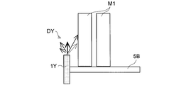
図12Bに示すように、背の高い商品に対して、その上方部分を特に照明するために、その上面から射出する構成とした棚板用導光素子1Yを用いた照明では、商品M1の上方部分を大きく散乱した光DYで照明するので、所望される表示ラベル部分を均一に照明することは困難であり、購入者にとっては好ましくない。
これに対し、本実施形態によれば、棚板用導光素子の全反射と所定角度範囲の拡散と射出面での斜め方向の屈折により、特定方向に配光制御して照明可能であるので、所望される特定方向を明るく効率よく均一に照明可能な棚板用導光素子および照明装置となる。
なお、点状光源としてチップ型のLED光源を用いた実施形態例としたが、その他の点状光源であってもよく、例えば、レンズ付きや砲弾型のLED光源を用いてもよい。
上記したように、本発明に係る棚板用導光素子によれば、点状光源とは別の位置の特定方向を効果的に照明することが可能となる。また、反射面に平行に近い射出面から斜め方向に射出するので、特定方向に高強度で光を照射し、且つ、第一反射面に備える拡散部を介して射出面色分散による色ムラを軽減して均一な色合いで照射可能となる。さらに、全反射光を利用して高効率反射した光を射出面から屈折させて射出するので、点状光源の光を配光制御して所望の特定方向に明るく効率よく均一に照明可能な棚板用導光素子を得ることができる。
また、本発明に係る照明装置によれば、点状光源の光を配光制御して所望の特定方向に明るく効率よく均一に照明可能な照明装置を得ることができる。
そのために、本発明に係る棚板用導光素子および照明装置は、上下に複数の棚板を備える多段式のショーケースの棚板に載置する背の高い商品を照明するための照明装置に好適に適用することができる。
1A~1H 棚板用導光素子
2 点状光源(光源、LED光源)
5、5A、5B 棚板
10A~10H 照明装置
11、11A~11H 入射面
12 反射面
12Aa~12Ha 第一反射面
12Ab~12Hb 第二反射面
13A~13H 射出面
14、14A~14C 拡散部
2 点状光源(光源、LED光源)
5、5A、5B 棚板
10A~10H 照明装置
11、11A~11H 入射面
12 反射面
12Aa~12Ha 第一反射面
12Ab~12Hb 第二反射面
13A~13H 射出面
14、14A~14C 拡散部
Claims (15)
- 光源から出射される光が入射する入射面と、入射した光を反射する反射面と、反射された光を射出する射出面を備えた導光素子であって、
前記反射面は、入射した光を全反射する第一反射面を備え、
前記射出面は、前記第一反射面により全反射された光の一部を屈折させて射出し、残りの光を全反射するように前記第一反射面に対して傾斜した射出面で、射出光の最大強度光は射出面法線方向に対して傾斜した方向に射出し、
前記第一反射面は入射した光を所定角度範囲に拡散しながら全反射する拡散部を備えると共に、
棚板の前端部に沿って設置され、棚板の少なくとも上下の一方を照明することを特徴とする棚板用導光素子。 - 前記拡散部は、色ムラの発生を抑制可能な拡散角度で拡散することを特徴とする請求項1に記載の棚板用導光素子。
- 前記射出光の最大強度光は、射出面法線方向に対して30度より大きな角度傾斜した方向に射出することを特徴とする請求項1または2に記載の棚板用導光素子。
- 前記射出面は、前記第一反射面に対して平行位置から1~30度傾斜していることを特徴とする請求項1から3のいずれかに記載の棚板用導光素子。
- 前記入射面は、この入射面に対して略垂直に入射する光が前記第一反射面から全反射されるように傾斜していることを特徴とする請求項1から4のいずれかに記載の棚板用導光素子。
- 前記入射面は、前記第一反射面に対して平行位置から50~80度傾斜していることを特徴とする請求項5に記載の棚板用導光素子。
- 前記入射面は前記点状光源を所定間隔で複数並設可能な程度に長寸とされ、この長手方向に沿って同寸の反射面と射出面を有することを特徴とする請求項1から6のいずれかに記載の棚板用導光素子。
- 前記反射面は、前記第一反射面に略平行に対向し、前記第一反射面から光を受けて前記第一反射面に向けて反射する第二反射面を有することを特徴とする請求項1から7のいずれかに記載の棚板用導光素子。
- 前記拡散部は、前記射出面に向けて反射光を反射する部位に設けられていることを特徴とする請求項1から8のいずれかに記載の棚板用導光素子。
- 光源と、該光源から出射される光が入射する入射面と、入射した光を反射する反射面と、反射された光を射出する射出面を備えた導光素子と、を備えた照明装置であって、
前記導光素子として請求項1から9のいずれかに記載された棚板用導光素子を備えたことを特徴とする照明装置。 - 前記棚板用導光素子は、第一および第二棚板用導光素子を有する一対二個の棚板用導光素子からなり、一つの前記光源が発する光を異なる二方向に導光することを特徴とする請求項10に記載の照明装置。
- 前記棚板用導光素子は、前記光源が発する光を異なる二方向に分岐する分岐部を備えた一体型であって、一つの前記光源が発する光を異なる二方向に導光する第一および第二導光部を有することを特徴とする請求項10に記載の照明装置。
- 前記光源は点状光源であることを特徴とする請求項10から12のいずれかに記載の照明装置。
- 前記点状光源はLED光源であることを特徴とする請求項13に記載の照明装置。
- 前記光源を所定間隔で複数並設し、この並設する長手方向に沿って長寸の入射面と反射面と射出面を有し、棚板の前端部に沿って設置することを特徴とする請求項10から14のいずれかに記載の照明装置。
Priority Applications (1)
| Application Number | Priority Date | Filing Date | Title |
|---|---|---|---|
| JP2012555786A JPWO2012105315A1 (ja) | 2011-02-04 | 2012-01-18 | 棚板用導光素子および照明装置 |
Applications Claiming Priority (2)
| Application Number | Priority Date | Filing Date | Title |
|---|---|---|---|
| JP2011023394 | 2011-02-04 | ||
| JP2011-023394 | 2011-02-04 |
Publications (1)
| Publication Number | Publication Date |
|---|---|
| WO2012105315A1 true WO2012105315A1 (ja) | 2012-08-09 |
Family
ID=46602535
Family Applications (1)
| Application Number | Title | Priority Date | Filing Date |
|---|---|---|---|
| PCT/JP2012/050894 Ceased WO2012105315A1 (ja) | 2011-02-04 | 2012-01-18 | 棚板用導光素子および照明装置 |
Country Status (2)
| Country | Link |
|---|---|
| JP (1) | JPWO2012105315A1 (ja) |
| WO (1) | WO2012105315A1 (ja) |
Cited By (5)
| Publication number | Priority date | Publication date | Assignee | Title |
|---|---|---|---|---|
| JP2017015840A (ja) * | 2015-06-29 | 2017-01-19 | 株式会社新陽社 | 発光素子を用いた細長い面発光表示器 |
| WO2018051100A1 (en) * | 2016-09-15 | 2018-03-22 | Artform International Limited | Product display and method of manufacture |
| EP3339728A1 (en) * | 2016-12-22 | 2018-06-27 | Self Electronics Co., Ltd. | Led strip light for shelf signboards |
| WO2022030538A1 (ja) * | 2020-08-06 | 2022-02-10 | マクセル株式会社 | 空間浮遊映像情報表示システムおよびそれに用いられる光源装置 |
| RU2835548C1 (ru) * | 2024-08-27 | 2025-02-26 | Акционерное общество "Международные услуги по маркетингу табака" | Устройство для размещения информации о никотинсодержащей продукции |
Citations (6)
| Publication number | Priority date | Publication date | Assignee | Title |
|---|---|---|---|---|
| JP2001133779A (ja) * | 1999-11-08 | 2001-05-18 | Hitachi Ltd | 液晶表示装置 |
| JP2006202639A (ja) * | 2005-01-21 | 2006-08-03 | Sony Corp | バックライト装置 |
| JP2007227356A (ja) * | 2006-01-30 | 2007-09-06 | Toyoda Gosei Co Ltd | 車両用灯具 |
| JP2009135116A (ja) * | 2002-11-29 | 2009-06-18 | Fujitsu Ltd | 面光源装置、プリズムシート、表示装置及び情報処理装置 |
| WO2009147877A1 (ja) * | 2008-06-04 | 2009-12-10 | シャープ株式会社 | 導光体、照明装置、および液晶表示装置 |
| JP2010082115A (ja) * | 2008-09-30 | 2010-04-15 | Sanyo Electric Co Ltd | ショーケース |
Family Cites Families (4)
| Publication number | Priority date | Publication date | Assignee | Title |
|---|---|---|---|---|
| JP4243635B2 (ja) * | 1993-03-03 | 2009-03-25 | シャープ株式会社 | 照明装置 |
| JP2004271871A (ja) * | 2003-03-07 | 2004-09-30 | Enplas Corp | 導光板,面光源装置及び液晶表示装置 |
| JP4383463B2 (ja) * | 2007-03-30 | 2009-12-16 | アルプス電気株式会社 | 照光式スイッチ装置 |
| JP2009080769A (ja) * | 2007-09-27 | 2009-04-16 | Sanden Corp | 紙幣識別装置 |
-
2012
- 2012-01-18 JP JP2012555786A patent/JPWO2012105315A1/ja active Pending
- 2012-01-18 WO PCT/JP2012/050894 patent/WO2012105315A1/ja not_active Ceased
Patent Citations (6)
| Publication number | Priority date | Publication date | Assignee | Title |
|---|---|---|---|---|
| JP2001133779A (ja) * | 1999-11-08 | 2001-05-18 | Hitachi Ltd | 液晶表示装置 |
| JP2009135116A (ja) * | 2002-11-29 | 2009-06-18 | Fujitsu Ltd | 面光源装置、プリズムシート、表示装置及び情報処理装置 |
| JP2006202639A (ja) * | 2005-01-21 | 2006-08-03 | Sony Corp | バックライト装置 |
| JP2007227356A (ja) * | 2006-01-30 | 2007-09-06 | Toyoda Gosei Co Ltd | 車両用灯具 |
| WO2009147877A1 (ja) * | 2008-06-04 | 2009-12-10 | シャープ株式会社 | 導光体、照明装置、および液晶表示装置 |
| JP2010082115A (ja) * | 2008-09-30 | 2010-04-15 | Sanyo Electric Co Ltd | ショーケース |
Cited By (5)
| Publication number | Priority date | Publication date | Assignee | Title |
|---|---|---|---|---|
| JP2017015840A (ja) * | 2015-06-29 | 2017-01-19 | 株式会社新陽社 | 発光素子を用いた細長い面発光表示器 |
| WO2018051100A1 (en) * | 2016-09-15 | 2018-03-22 | Artform International Limited | Product display and method of manufacture |
| EP3339728A1 (en) * | 2016-12-22 | 2018-06-27 | Self Electronics Co., Ltd. | Led strip light for shelf signboards |
| WO2022030538A1 (ja) * | 2020-08-06 | 2022-02-10 | マクセル株式会社 | 空間浮遊映像情報表示システムおよびそれに用いられる光源装置 |
| RU2835548C1 (ru) * | 2024-08-27 | 2025-02-26 | Акционерное общество "Международные услуги по маркетингу табака" | Устройство для размещения информации о никотинсодержащей продукции |
Also Published As
| Publication number | Publication date |
|---|---|
| JPWO2012105315A1 (ja) | 2014-07-03 |
Similar Documents
| Publication | Publication Date | Title |
|---|---|---|
| JP5794295B2 (ja) | 照明装置、棚板ユニット、およびショーケース | |
| JP5768821B2 (ja) | 照明装置 | |
| TWI273291B (en) | Surface light source and light guide plate used therein | |
| JP5099999B2 (ja) | バックライトユニット及びそれを採用した液晶表示装置 | |
| US9562670B2 (en) | Illumination system, luminaire, collimator, and display device | |
| US6486790B1 (en) | White-LED luminous signalling device | |
| CN102575823B (zh) | 以均匀的光线分布照亮灯箱的led发光元件 | |
| US10948150B2 (en) | Multi-beam vehicle light | |
| WO2012165191A1 (ja) | 照明装置、この照明装置を備えた棚板ユニットおよびショーケース | |
| TWI276890B (en) | Light emitting module and plane light source device | |
| JP2013182729A (ja) | 照明モジュールおよびそれを備えた照明装置 | |
| JPWO2012165190A1 (ja) | 照明装置、この照明装置を備えた棚板ユニットおよびショーケース | |
| CN103727454A (zh) | 导光板、发光模块及显示装置 | |
| WO2012105315A1 (ja) | 棚板用導光素子および照明装置 | |
| JP2014099343A (ja) | 照明装置及びショーケース | |
| JP2014154436A (ja) | 照明器具 | |
| JP2007335313A (ja) | 光源装置、表示装置 | |
| US20100109576A1 (en) | General illumination system and an illuminaire | |
| JP5588217B2 (ja) | 照明装置 | |
| JP2012142252A (ja) | 照明装置及びそれを備えたショーケース | |
| CN115419863B (zh) | 均匀照明透镜及其灯具 | |
| JP2014056787A (ja) | 照明装置 | |
| CN203099686U (zh) | 透镜、led模组及使用该led模组的照明系统 | |
| JP2005285704A (ja) | 導光部材及びこの導光部材を用いた照明装置 | |
| JP2008234876A (ja) | 照明装置 |
Legal Events
| Date | Code | Title | Description |
|---|---|---|---|
| 121 | Ep: the epo has been informed by wipo that ep was designated in this application |
Ref document number: 12741492 Country of ref document: EP Kind code of ref document: A1 |
|
| ENP | Entry into the national phase |
Ref document number: 2012555786 Country of ref document: JP Kind code of ref document: A |
|
| NENP | Non-entry into the national phase |
Ref country code: DE |
|
| 122 | Ep: pct application non-entry in european phase |
Ref document number: 12741492 Country of ref document: EP Kind code of ref document: A1 |