WO2012105116A1 - 真空ポンプの回転体と、これに対向設置する固定部材、及び、これらを備えた真空ポンプ - Google Patents
真空ポンプの回転体と、これに対向設置する固定部材、及び、これらを備えた真空ポンプ Download PDFInfo
- Publication number
- WO2012105116A1 WO2012105116A1 PCT/JP2011/077301 JP2011077301W WO2012105116A1 WO 2012105116 A1 WO2012105116 A1 WO 2012105116A1 JP 2011077301 W JP2011077301 W JP 2011077301W WO 2012105116 A1 WO2012105116 A1 WO 2012105116A1
- Authority
- WO
- WIPO (PCT)
- Prior art keywords
- vacuum pump
- rotor
- rotating body
- pump
- reinforced plastic
- Prior art date
- Legal status (The legal status is an assumption and is not a legal conclusion. Google has not performed a legal analysis and makes no representation as to the accuracy of the status listed.)
- Ceased
Links
Images
Classifications
-
- F—MECHANICAL ENGINEERING; LIGHTING; HEATING; WEAPONS; BLASTING
- F04—POSITIVE - DISPLACEMENT MACHINES FOR LIQUIDS; PUMPS FOR LIQUIDS OR ELASTIC FLUIDS
- F04D—NON-POSITIVE-DISPLACEMENT PUMPS
- F04D29/00—Details, component parts, or accessories
- F04D29/02—Selection of particular materials
-
- F—MECHANICAL ENGINEERING; LIGHTING; HEATING; WEAPONS; BLASTING
- F04—POSITIVE - DISPLACEMENT MACHINES FOR LIQUIDS; PUMPS FOR LIQUIDS OR ELASTIC FLUIDS
- F04D—NON-POSITIVE-DISPLACEMENT PUMPS
- F04D19/00—Axial-flow pumps
- F04D19/02—Multi-stage pumps
- F04D19/04—Multi-stage pumps specially adapted to the production of a high vacuum, e.g. molecular pumps
- F04D19/042—Turbomolecular vacuum pumps
-
- F—MECHANICAL ENGINEERING; LIGHTING; HEATING; WEAPONS; BLASTING
- F04—POSITIVE - DISPLACEMENT MACHINES FOR LIQUIDS; PUMPS FOR LIQUIDS OR ELASTIC FLUIDS
- F04D—NON-POSITIVE-DISPLACEMENT PUMPS
- F04D19/00—Axial-flow pumps
- F04D19/02—Multi-stage pumps
- F04D19/04—Multi-stage pumps specially adapted to the production of a high vacuum, e.g. molecular pumps
- F04D19/044—Holweck-type pumps
-
- F—MECHANICAL ENGINEERING; LIGHTING; HEATING; WEAPONS; BLASTING
- F04—POSITIVE - DISPLACEMENT MACHINES FOR LIQUIDS; PUMPS FOR LIQUIDS OR ELASTIC FLUIDS
- F04D—NON-POSITIVE-DISPLACEMENT PUMPS
- F04D29/00—Details, component parts, or accessories
- F04D29/02—Selection of particular materials
- F04D29/023—Selection of particular materials especially adapted for elastic fluid pumps
-
- F—MECHANICAL ENGINEERING; LIGHTING; HEATING; WEAPONS; BLASTING
- F05—INDEXING SCHEMES RELATING TO ENGINES OR PUMPS IN VARIOUS SUBCLASSES OF CLASSES F01-F04
- F05D—INDEXING SCHEME FOR ASPECTS RELATING TO NON-POSITIVE-DISPLACEMENT MACHINES OR ENGINES, GAS-TURBINES OR JET-PROPULSION PLANTS
- F05D2230/00—Manufacture
- F05D2230/30—Manufacture with deposition of material
- F05D2230/31—Layer deposition
-
- F—MECHANICAL ENGINEERING; LIGHTING; HEATING; WEAPONS; BLASTING
- F05—INDEXING SCHEMES RELATING TO ENGINES OR PUMPS IN VARIOUS SUBCLASSES OF CLASSES F01-F04
- F05D—INDEXING SCHEME FOR ASPECTS RELATING TO NON-POSITIVE-DISPLACEMENT MACHINES OR ENGINES, GAS-TURBINES OR JET-PROPULSION PLANTS
- F05D2230/00—Manufacture
- F05D2230/90—Coating; Surface treatment
-
- F—MECHANICAL ENGINEERING; LIGHTING; HEATING; WEAPONS; BLASTING
- F05—INDEXING SCHEMES RELATING TO ENGINES OR PUMPS IN VARIOUS SUBCLASSES OF CLASSES F01-F04
- F05D—INDEXING SCHEME FOR ASPECTS RELATING TO NON-POSITIVE-DISPLACEMENT MACHINES OR ENGINES, GAS-TURBINES OR JET-PROPULSION PLANTS
- F05D2260/00—Function
- F05D2260/95—Preventing corrosion
-
- F—MECHANICAL ENGINEERING; LIGHTING; HEATING; WEAPONS; BLASTING
- F05—INDEXING SCHEMES RELATING TO ENGINES OR PUMPS IN VARIOUS SUBCLASSES OF CLASSES F01-F04
- F05D—INDEXING SCHEME FOR ASPECTS RELATING TO NON-POSITIVE-DISPLACEMENT MACHINES OR ENGINES, GAS-TURBINES OR JET-PROPULSION PLANTS
- F05D2300/00—Materials; Properties thereof
- F05D2300/10—Metals, alloys or intermetallic compounds
- F05D2300/17—Alloys
- F05D2300/173—Aluminium alloys, e.g. AlCuMgPb
-
- F—MECHANICAL ENGINEERING; LIGHTING; HEATING; WEAPONS; BLASTING
- F05—INDEXING SCHEMES RELATING TO ENGINES OR PUMPS IN VARIOUS SUBCLASSES OF CLASSES F01-F04
- F05D—INDEXING SCHEME FOR ASPECTS RELATING TO NON-POSITIVE-DISPLACEMENT MACHINES OR ENGINES, GAS-TURBINES OR JET-PROPULSION PLANTS
- F05D2300/00—Materials; Properties thereof
- F05D2300/20—Oxide or non-oxide ceramics
- F05D2300/21—Oxide ceramics
- F05D2300/2112—Aluminium oxides
-
- F—MECHANICAL ENGINEERING; LIGHTING; HEATING; WEAPONS; BLASTING
- F05—INDEXING SCHEMES RELATING TO ENGINES OR PUMPS IN VARIOUS SUBCLASSES OF CLASSES F01-F04
- F05D—INDEXING SCHEME FOR ASPECTS RELATING TO NON-POSITIVE-DISPLACEMENT MACHINES OR ENGINES, GAS-TURBINES OR JET-PROPULSION PLANTS
- F05D2300/00—Materials; Properties thereof
- F05D2300/40—Organic materials
- F05D2300/43—Synthetic polymers, e.g. plastics; Rubber
-
- F—MECHANICAL ENGINEERING; LIGHTING; HEATING; WEAPONS; BLASTING
- F05—INDEXING SCHEMES RELATING TO ENGINES OR PUMPS IN VARIOUS SUBCLASSES OF CLASSES F01-F04
- F05D—INDEXING SCHEME FOR ASPECTS RELATING TO NON-POSITIVE-DISPLACEMENT MACHINES OR ENGINES, GAS-TURBINES OR JET-PROPULSION PLANTS
- F05D2300/00—Materials; Properties thereof
- F05D2300/60—Properties or characteristics given to material by treatment or manufacturing
- F05D2300/603—Composites; e.g. fibre-reinforced
-
- F—MECHANICAL ENGINEERING; LIGHTING; HEATING; WEAPONS; BLASTING
- F05—INDEXING SCHEMES RELATING TO ENGINES OR PUMPS IN VARIOUS SUBCLASSES OF CLASSES F01-F04
- F05D—INDEXING SCHEME FOR ASPECTS RELATING TO NON-POSITIVE-DISPLACEMENT MACHINES OR ENGINES, GAS-TURBINES OR JET-PROPULSION PLANTS
- F05D2300/00—Materials; Properties thereof
- F05D2300/60—Properties or characteristics given to material by treatment or manufacturing
- F05D2300/611—Coating
Definitions
- this type of vacuum pump for example, a composite turbo molecular pump described in Patent Document 1 is known.
- this composite turbomolecular pump exhausts gas by the interaction between the rotary blade (2a) and the fixed blade (2b).
- a turbo molecular pump part (2) as a blade exhaust part and a thread groove pump part (3) for exhausting gas through a thread groove (7a) are provided, and the rotor (4a) of the turbo molecular pump part (2) is made of aluminum.
- the rotor (6) of the thread groove pump section (3) is made of an alloy, and is made of CFRP (carbon fiber reinforced plastics).
- the composite molecular pump including the turbo molecular pump part (2) and the thread groove pump part (3) as described in Patent Document 1 described above is light and strong in the rotor (6) of the thread groove pump part (3). Since the part is made of a high fiber reinforced plastic material, by increasing the rotational speed of the rotor (6) or by enlarging the diameter of the rotor (6) rather than the rotor made of aluminum alloy, The peripheral speed of the rotor (6) can be improved, and the exhaust capacity of the thread groove pump part (3) can be increased.
- the peripheral speed of the rotor (6) reaches a speed close to the sound speed of the exhausted gas in the thread groove pump section (3).
- the temperature of the rotor (6) rises due to the heat (friction heat) generated by the friction between the gas exhausted in the groove pump section (3) and the rotor (6), and the CFRP which is the constituent material of the rotor (6) is allowed. If the temperature is exceeded, the strength of the CFRP material is reduced, and heat resistance problems such as the rotor (6) becoming brittle and easily broken due to thermal modification of the CFRP material occur. For this reason, it is difficult to improve the maximum flow rate at the same time as improving the exhaust performance in the pump whose exhaust performance is improved by improving the peripheral speed of the rotor (6).
- the heat accumulated in the rotor (6) generally includes heat conduction through the exhaust gas (first heat radiation route), heat conduction through the bearing of the rotor (6) (second heat radiation route), rotor
- heat is radiated by radiation from the surface of (6) (third heat radiation route)
- a non-contact bearing such as a magnetic bearing
- the rotor via the second heat radiation route The heat dissipation of (6) cannot be expected.
- the heat radiation of the rotor (6) through the first heat radiation route can hardly be expected depending on the type of gas to be exhausted.
- CFRP which is the constituent material of the rotor (6)
- CFRP has a lower thermal conductivity and temperature distribution than the aluminum alloy that is the constituent material of the rotor (4a) and the rotor blade (2a) of the turbo molecular pump section (2). Tends to occur.
- the pressure in the thread groove pump (3) is high and the friction with the gas is large. The periphery of the lower end portion of the rotor (6) close to the exhaust port (8) is easily broken by the high temperature caused by the frictional heat.
- the present invention has been made to solve the above-mentioned problems, and its purpose is to provide a vacuum suitable for obtaining a highly reliable vacuum pump that simultaneously achieves an improvement in exhaust performance and an increase in maximum flow rate. It is to provide a rotary body of a pump, a fixing member provided opposite to the rotary body, and a vacuum pump including these.
- a rotary body of a vacuum pump is a rotary body of a vacuum pump that is partially or entirely made of fiber reinforced plastic and exhausts gas by rotation, and the rotary body includes: A corrosion-resistant treatment layer is provided on the fiber reinforced plastic portion which is the base material, and a high emissivity layer having a higher emissivity than the corrosion-resistant treatment layer is provided on the corrosion-resistant treatment layer.
- the high emissivity layer is an oxide film layer formed by oxidizing a surface of a metal film formed on the corrosion-resistant treatment layer, or a DLC coating on the corrosion-resistant treatment layer. It is good also as what consists of a DLC layer formed by processing.
- the fixing member disposed opposite to the rotating body of the vacuum pump according to the present invention is opposed to the inner peripheral surface or the outer peripheral surface of the rotating body of the vacuum pump, part or all of which is made of fiber-reinforced plastic, and A fixing member of a vacuum pump that forms a spiral thread groove exhaust passage for exhausting gas between the fixing members on the opposing surface of the fixing member facing the fiber reinforced plastic portion of the rotating body A high emissivity layer having a higher emissivity than that of the base material is provided.
- the high emissivity layer is an oxide film layer formed by oxidizing a surface of an aluminum alloy that is a base material of the fixing member, or the base It may be composed of a coating film layer formed by coating the surface of the fixing member with a material having a higher emissivity than the aluminum alloy material.
- the vacuum pump of the present invention is characterized in that it includes a rotating body of the vacuum pump, or includes a rotating body of the vacuum pump and a fixing member.
- the rotary body of the vacuum pump is provided with a corrosion-resistant treatment layer on a fiber reinforced plastic portion as a base material, and the corrosion-resistant treatment layer is provided on the corrosion-resistant treatment layer.
- a configuration was adopted in which a high emissivity layer having a higher emissivity than the treatment layer was provided.
- the fixing member is provided on a surface (facing surface) that faces the fiber-reinforced plastic portion of the rotating body.
- the structure provided with the high emissivity layer whose emissivity is higher than the base material of the fixing member was adopted.
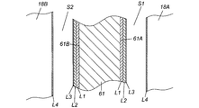
- FIG. 1 is an enlarged cross-sectional view of a first cylindrical body made of fiber-reinforced plastic that constitutes a rotor that is a rotating body of the vacuum pump of FIG. 1 and a thread groove pump portion stator that is a fixing member of the vacuum pump facing the first cylinder.
- FIG. 1 is an enlarged cross-sectional view of a first cylindrical body made of fiber-reinforced plastic that constitutes a rotor that is a rotating body of the vacuum pump of FIG. 1 and a thread groove pump portion stator that is a fixing member of the vacuum pump facing the first cylinder.
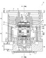
- FIG. 1 is a sectional view of a vacuum pump to which the present invention is applied.
- the vacuum pump P shown in the figure is used as, for example, a gas exhaust means for a process chamber or other sealed chamber in a semiconductor manufacturing apparatus, a flat panel display manufacturing apparatus, or a solar panel manufacturing apparatus.
- the vacuum pump P includes a blade exhaust part Pt that exhausts gas by the rotary blade 13 and the fixed blade 14 in the outer case 1, a screw groove pump part Ps that exhausts gas using the screw grooves 19A and 19B, These drive systems are included.
- the outer case 1 has a bottomed cylindrical shape in which a cylindrical pump case 1A and a bottomed cylindrical pump base 1B are integrally connected with bolts in the cylinder axis direction.
- the upper end portion side of the pump case 1A is opened as a gas intake port 2, and a gas exhaust port 3 is provided on the side surface of the lower end portion of the pump base 1B.
- the gas inlet 2 is connected to a sealed chamber (not shown), which is a high vacuum, such as a process chamber of a semiconductor manufacturing apparatus, by a bolt (not shown) provided on the flange 1C on the upper edge of the pump case 1A.
- the gas exhaust port 3 is connected so as to communicate with an auxiliary pump (not shown).
- a cylindrical stator column 4 containing various electrical components is provided in the center of the pump case 1A, and the stator column 4 is erected in such a manner that its lower end is screwed and fixed onto the pump base 1B. is there.
- a rotor shaft 5 is provided inside the stator column 4, and the rotor shaft 5 is arranged such that its upper end portion faces the gas inlet 2 and its lower end portion faces the pump base 1B. is there. Further, the upper end portion of the rotor shaft 5 is provided so as to protrude upward from the cylindrical upper end surface of the stator column 4.
- the rotor shaft 5 is supported by a radial magnetic bearing 10 and an axial magnetic bearing 11 so as to be rotatable in the radial direction and the axial direction, and is rotated by a drive motor 12 in this state.
- the drive motor 12 has a structure including a stator 12A and a rotor 12B, and is provided near the center of the rotor shaft 5.
- the stator 12 ⁇ / b> A of the drive motor 12 is installed inside the stator column 4, and the rotor 12 ⁇ / b> B of the drive motor 12 is integrally mounted on the outer peripheral surface side of the rotor shaft 5.
- Two sets of radial magnetic bearings 10 are arranged one by one above and below the drive motor 12, and one set of axial magnetic bearings 11 is arranged on the lower end side of the rotor shaft 5.
- the two sets of radial magnetic bearings 10 and 10 are respectively a radial electromagnet target 10A attached to the outer peripheral surface of the rotor shaft 5, a plurality of radial electromagnets 10B installed on the inner side surface of the stator column 4 facing this, and a radial direction displacement sensor. 10C is comprised.
- the radial electromagnet target 10A is made of a laminated steel plate in which steel plates of high permeability material are laminated, and the radial electromagnet 10B attracts the rotor shaft 5 with a magnetic force in the radial direction through the radial electromagnet target 10A.
- the radial direction displacement sensor 10 ⁇ / b> C detects the radial displacement of the rotor shaft 5.
- the rotor shaft 5 is levitated and supported by a magnetic force at a predetermined position in the radial direction.
- the axial magnetic bearing 11 includes a disk-shaped armature disk 11A attached to the outer periphery of the lower end portion of the rotor shaft 5, an axial electromagnet 11B facing up and down across the armature disk 11A, and a position slightly away from the lower end surface of the rotor shaft 5. And an axial direction displacement sensor 11C installed in The armature disk 11A is made of a material having high magnetic permeability, and the upper and lower axial electromagnets 11B attract the armature disk 11A from the upper and lower directions with a magnetic force.
- the axial direction displacement sensor 11 ⁇ / b> C detects the axial displacement of the rotor shaft 5.
- the rotor shaft 5 is levitated and supported at a predetermined position in the axial direction by controlling the excitation current of the upper and lower axial electromagnets 11B based on the detection value (axial displacement of the rotor shaft 5) detected by the axial direction displacement sensor 11C.
- a rotor 6 is provided outside the stator column 4 as a rotating body of the vacuum pump P.
- the rotor 6 has a cylindrical shape surrounding the outer periphery of the stator column 4, and has two cylindrical bodies (a first cylindrical body 61 and a first cylindrical body 61) having different diameters via an annular plate-shaped support member 60 positioned substantially in the middle. 2 cylinders 62) are connected in the axial direction.
- the support member 60 is integrally provided at the lower end of the second cylindrical body 62, and the ring-shaped convex portion 60 ⁇ / b> A is integrally formed on the back outer peripheral portion of the support member 60.
- the first cylinder 61 and the second cylinder 62 are connected in the axial direction by press-fitting and mounting the first cylinder 61 on the outer periphery of the ring-shaped convex portion 60A. It is configured.
- An end member 63 is provided at the upper end of the second cylindrical body 62, and the rotor 6 and the rotor shaft 5 are integrated via the end member 63.
- a boss hole 7 is provided at the center of the end member 63, and a stepped shoulder (hereinafter referred to as “rotor shaft shoulder” is formed on the outer periphery of the upper end of the rotor shaft 5. Part 9 "). Then, by inserting the tip of the rotor shaft 5 above the rotor shaft shoulder 9 into the boss hole 7 of the end member 63 and fastening and fixing the end member 63 and the rotor shaft shoulder 9 with bolts, The rotor shaft 5 is integrated.
- the first cylinder 61 includes AFPR (aramid fiber reinforced plastic), BFRP (boron fiber reinforced plastic), It is formed of a fiber reinforced plastic such as CFRP (carbon fiber reinforced plastic), DFRP (polyethylene fiber reinforced plastic), or GFRP (glass fiber reinforced plastic).
- CFRP carbon fiber reinforced plastic
- DFRP polyethylene fiber reinforced plastic
- GFRP glass fiber reinforced plastic
- the vacuum pump P of FIG. 1 employs the rotor 6 having a configuration including the first cylindrical body 61 made of fiber reinforced plastic as an example of a rotating body partially made of fiber reinforced plastic. Is.
- the rotor 6 is supported by the radial magnetic bearings 10 and 10 and the axial magnetic bearing 11 via the rotor shaft 5 so as to be rotatable around its axis (rotor shaft 5). Therefore, in the vacuum pump P of FIG. 1, the rotor shaft 5, the radial magnetic bearings 10 and 10, and the axial magnetic bearing 11 function as support means that rotatably supports the rotor 6 about its axis. Further, since the rotor 6 rotates integrally with the rotor shaft 5, the drive motor 12 that rotationally drives the rotor shaft 5 functions as drive means that rotationally drives the rotor 6.
- the vacuum pump P shown in FIG. 1 is configured so that the upstream from the substantially middle of the rotor 6 (the range from the substantially middle of the rotor 6 to the gas inlet 2 side end of the rotor 6) functions as the blade exhaust part Pt. is there.
- the blade exhaust part Pt will be described in detail below.
- a plurality of rotor blades 13 are integrally provided on the outer circumferential surface of the rotor 6 (specifically, the outer circumferential surface of the second cylindrical body 62) on the upstream side of the middle of the rotor 6.
- the plurality of rotor blades 13 are arranged radially about the rotation axis of the rotor 6 (rotor shaft 5) or the axis of the outer case 1 (hereinafter referred to as “pump axis”).
- a plurality of fixed wings 14 are provided on the inner peripheral surface side of the pump case 1A, and these fixed wings 14 are arranged radially around the pump axis.
- the rotor blades 13 and the stationary blades 14 are alternately arranged in multiple stages along the pump axis, thereby forming the blade exhaust part Pt.
- Each of the rotor blades 13 is a blade-like cut product that is cut and formed integrally with the outer diameter machining portion of the rotor 6 and is inclined at an angle that is optimal for exhaust of gas molecules.
- Each fixed blade 14 is also inclined at an angle optimum for exhausting gas molecules.
- the vacuum pump P in FIG. 1 is configured so that the downstream side from the substantially middle of the rotor 6 (the range from the substantially middle of the rotor 6 to the gas exhaust port 3 side end of the rotor 6) functions as the thread groove pump part Ps. is there.
- the thread groove pump portion Ps will be described in detail below.
- a rotor 6 (specifically, a portion of the first cylindrical body 61) on the downstream side from the substantially middle of the rotor 6 is a portion that rotates as a rotating member of the thread groove pump portion Ps. It is configured to be inserted and accommodated between the double cylindrical thread groove pump part stators 18A and 18B via a predetermined gap.
- the outer thread groove pump section stator 18A serves as a fixing member for the vacuum pump P located outside the rotor 6 and is the outer periphery of the rotor 6 (abbreviation of the rotor 6). It is provided so as to face the outer peripheral surface of the rotor 6 by being disposed so as to surround a portion downstream from the middle. Further, a screw groove 19A that changes to a tapered cone shape whose depth is reduced in diameter toward the bottom is formed in the inner peripheral portion of the outer screw groove pump portion stator 18A.
- the thread groove 19A is spirally engraved from the upper end to the lower end of the thread groove pump portion stator 18A, and the screw groove 19A causes a spiral between the rotor 6 and the outer thread groove pump portion stator 18A.
- a thread groove pump flow path (hereinafter referred to as “outer thread groove pump flow path S1”) is formed. Note that the lower end of the outer thread groove pump portion stator 18A is supported by the pump base 1B.
- the inner thread groove pump portion stator 18 ⁇ / b> B is disposed so as to be surrounded by the inner periphery of the rotor 6 as a fixing member of the vacuum pump P located inside the rotor 6, so as to face the inner peripheral surface of the rotor 6.
- a thread groove 19B is formed in the outer peripheral portion of the inner thread groove pump portion stator 18B.
- a spiral thread groove pump flow path (hereinafter referred to as “inner thread groove pump flow path S2”) is also formed between the rotor 6 and the inner thread groove pump portion stator 18B. Note that the lower end portion of the inner thread groove pump portion stator 18B is also supported by the pump base 1B.
- the thread groove pump portion Ps gas is compressed and transferred by the drag effect on the outer circumferential surface of the thread groove 19A and the rotor 6 and the drag effect on the inner circumferential surface of the thread groove 19B and the rotor 6, so that the depth of the thread groove 19A is increased.
- the depth is deepest on the upstream inlet side (passage opening end closer to the gas intake port 2) of the outer thread groove pump flow path S1, and is the deepest on the downstream outlet side (passage opening end closer to the gas exhaust port 3). It is set to be shallow. The same applies to the thread groove 19B.
- the upstream inlet of the outer thread groove pump flow path S1 is the lowermost blade (the fixed blade 14 in the example of FIG. 1) of the rotor blades 13 and the fixed blades 14 arranged in multiple stages and a communication opening H described later. It communicates with a gap between the upstream ends (hereinafter referred to as “final gap G”), and the downstream outlet of the passage S1 is configured to communicate with the gas exhaust port 3 side.
- the upstream inlet of the inner thread groove pump flow path S2 opens toward the inner peripheral surface of the rotor 6 substantially in the middle of the rotor 6, and the downstream outlet of the passage S2 joins the downstream outlet of the outer thread groove pump flow path S1. Thus, it is configured to communicate with the gas exhaust port 3.
- a communication opening H is formed substantially in the middle of the rotor 6, and the communication opening H is formed so as to penetrate the front and back surfaces of the support member 60. It functions to lead a part to the inner thread pump channel S2.
- the rotor 6 is provided with a corrosion-resistant treatment layer L1 on the fiber reinforced plastic portion (the surface of the first cylindrical body 61 in the example shown in the figure), which is the base material.
- a high emissivity layer L3 having a higher emissivity than the anticorrosion treatment layer L1 is provided on the anticorrosion treatment layer L1.
- the vacuum pump P in FIG. 1 is used in an environment in which corrosive gas that decomposes the plastic component is exhausted. Therefore, the fiber reinforced plastic portion of the rotor 6 (the first cylinder 61 in the example of FIG. 1) is corrosive. As a means for protecting from gas, as described above, the surface of the first cylindrical body 61 is protected by the corrosion-resistant treatment layer L1 such as nickel alloy.
- the fiber reinforced plastic forming the first cylindrical body 61 which is a part of the rotor has a lower thermal conductivity than the aluminum or the alloy forming the other part of the rotor 6 and generates a temperature distribution. Easy to do.
- the first cylinder 61 has a relatively high temperature due to heat (friction heat) generated by friction with the gas to be exhausted at the end portion on the gas exhaust port 3 side where the pressure is high.
- the corrosion-resistant treatment layer L1 is provided on the first cylindrical body 61 (fiber reinforced plastic portion of the rotor 6), and a higher level is provided on the corrosion-resistant treatment layer L1.
- the emissivity layer L3 By providing the emissivity layer L3, the emissivity of the first cylinder 61 is increased. Therefore, heat generated in the first cylinder 61 is easily released by radiation, and the outer and inner thread groove pumps.
- the first cylinder 61 having a high pressure near the exhaust port side end becomes a high temperature due to the frictional heat described above and effectively prevents a malfunction that exceeds the allowable temperature of the fiber reinforced plastic. .
- the corrosion-resistant layer L1 on the inner peripheral surface of the rotor 6 is made of a first metal film having excellent corrosion resistance, such as a nickel alloy, and is formed so as to entirely cover the outer peripheral surface of the first cylindrical body 61.
- the high emissivity layer L3 covering the corrosion resistant layer L1 forms a second metal film L2 such as an aluminum alloy or a nickel alloy on the corrosion resistant layer L1, and the surface of the second metal film L2 Is formed so as to entirely cover the corrosion-resistant layer L1.
- the high emissivity layer L3 there is also a method of oxidizing the surface of the first metal coating (corrosion resistant layer L1) and adopting the oxide film layer as the high emissivity layer L3. Conceivable.
- the corrosion-resistant treatment layer L1 is formed by electroless Ni—P plating treatment, pinholes are generated in the corrosion-resistant treatment layer L1, and oxidation of the corrosion-resistant treatment layer L1 having pinholes occurs.
- the corrosion-resistant layer L1 is easily damaged and destroyed near the pinholes, so that the protection function of the first cylindrical body 61 (made of fiber-reinforced plastic) by the corrosion-resistant layer L1 is impaired.
- the above-described method that is, on the corrosion-resistant layer (first metal coating) L1.
- the high emissivity layer L3 is formed by oxidizing the surface of the second metal film L2 after protecting the corrosion-resistant layer L1 with the second metal film L2 by forming the second metal film L2. Preferably formed.
- the corrosion-resistant layer L1 (first metal film) and the second metal film L2 described above can be formed by, for example, an electrolytic plating method, an electroless plating method, or a sputtering method. .
- a DLC layer formed by performing DLC (Diamond Like Carbon) coating treatment on the corrosion-resistant treatment layer L1 Can also be adopted.
- the screw grooves 19A and 19B described above are formed on the opposing surfaces of the outer screw groove pump portion stator 18A and the inner screw groove pump portion stator 18B, the high emissivity layer provided on the opposite surfaces. L4 may be formed on the inner surface and the side surface of the screw grooves 19A and 19B in addition to being formed on the screw thread portions of the screw grooves 19A and 19B.
- the high emissivity layer L4 on the opposite surface of the fixing member is formed, for example, when the fixing member is formed of aluminum or an alloy thereof.
- An oxide film layer formed by oxidizing the surface of the alloy can be employed.
- emissivity is higher than aluminum or an alloy thereof, which is a base material of the fixing member (screw groove pump stators 18A and 18B) such as fluorine resin or epoxy resin, for example.
- a coating film layer formed by coating the surface of the fixing member with a high material, or a DLC layer formed by applying a DLC coating process to the surface of the fixing member can also be employed.
- the thread groove pump portion stators 18A and 18B are used as means for guiding and escaping the heat inside the pump to the outside.
- the thread groove pump stators 18A and 18B are made of a metal material having high thermal conductivity such as aluminum or an alloy thereof, the surface radiation rate is low, and the fiber reinforced plastic part (the first part of the rotor 6) 1 has a low ability to receive by radiation of the cylindrical body 61).
- the capability is enhanced by the high emissivity layer L4, so that the thread groove pump portion stators 18A and 18B efficiently receive the heat of the fiber reinforced plastic portion of the rotor 6 by radiation. It is possible to guide the received heat to the outside and escape.
- the corrosion-resistant treatment layer L1 is provided on the fiber-reinforced plastic portion (the first cylindrical body 61), and the corrosion resistance thereof.
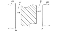
- the configuration in which the high emissivity layer L3 is provided on the treatment layer L1 is an example applied when the vacuum pump P of FIG. 1 is used in an environment in which a corrosive gas that decomposes a plastic component is exhausted. Therefore, when the vacuum pump P of FIG. 1 is used in an environment in which non-corrosive gas is exhausted, the corrosion-resistant treatment layer L1 may be omitted from the above configuration as shown in FIG.
- the fiber-reinforced plastic forming the first cylinder 61 of the rotor 6 forms a rotor component other than the first cylinder 61 (second cylinder 62, support member 60, end member 63). Since the emissivity is higher than that of aluminum or its alloy, etc., the high emissivity layer L3 may be omitted together with the second metal coating L2 in the above configuration as shown in FIG.
- Thread Groove Pump Stator 18A, 18B (Same Vacuum) Opposing Fiber Reinforced Plastic Part (First Cylinder 61) of Rotor 6 It is only necessary to provide a high emissivity layer L4 having a higher emissivity than aluminum or an alloy thereof as a base material of the thread groove pump portion stators 18A and 18B on the opposite surface of the fixing member of the pump P (see FIG. 3).
- heat released by radiation from the fiber reinforced plastic portion of the rotor 6 can be efficiently received by the high emissivity layers of the thread groove pump portion stators 18A and 18B.
- the amount of heat accumulated in the reinforced plastic portion decreases, and the temperature of the fiber reinforced plastic portion (first cylinder 61) of the rotor 6 increases due to heat (friction heat) generated by friction between the exhaust gas and the rotor 6. A situation where the allowable temperature is exceeded is effectively prevented.
- the embodiment described above is an example in which the present invention is applied to a structure in which a part of the rotor 6 (specifically, a part of the first cylindrical body 61) which is a rotating body of the vacuum pump P is made of fiber reinforced plastic.
- the present invention is not limited to this example, and can also be applied to a structure in which the entire rotor 6 (including the rotary blades 13) is made of fiber reinforced plastic.
Landscapes
- Engineering & Computer Science (AREA)
- Mechanical Engineering (AREA)
- General Engineering & Computer Science (AREA)
- Non-Positive Displacement Air Blowers (AREA)
Abstract
【課題】排気性能の向上と、連続的に排気可能なガス流量(=最大流量)の向上と、を同時に実現する信頼性の高い真空ポンプを得るのに好適な真空ポンプの回転体と、これに対向する固定部材、及び、これらを備えた真空ポンプを提供する。 【解決手段】真空ポンプPの回転体(ロータ6)は、その一部(第1の筒体61)が繊維強化プラスティックからなり、回転によりガスを排気するように構成されていて、その母材である繊維強化プラスティック部上には耐食処理層L1が設けられ、この耐食処理層L1上には該耐食処理層L1より輻射率の高い高輻射率層L3が設けられる。真空ポンプPの回転体と対向する固定部材(ネジ溝ポンプ部ステータ18A、18B)は、前記回転体の繊維強化プラスティック部(第1の筒体61)と対向する面(対向面)に、その固定部材の母材より輻射率の高い高輻射率層L4が設けられる。
Description
本発明は、例えば半導体製造装置、フラット・パネル・ディスプレイ製造装置、ソーラー・パネル製造装置におけるプロセスチャンバやその他の密閉チャンバ内のガスを真空排気する手段等として利用される真空ポンプの回転体と、これに対向設置する固定部材、及び、これらを備えた真空ポンプに関し、特に、排気性能の向上と、連続的に排気可能なガス流量(=最大流量)の向上と、を同時に実現できるようにしたものである。
従来この種の真空ポンプとしては、例えば、特許文献1に記載の複合型ターボ分子ポンプが知られている。この複合型ターボ分子ポンプは、同文献1の図1とその請求項1並びに段落0012~0013の記載から分かるように、回転翼(2a)と固定翼(2b)の相互作用によりガスを排気する翼排気部としてターボ分子ポンプ部(2)、及び、ネジ溝(7a)によりガスを排気するネジ溝ポンプ部(3)を備えており、ターボ分子ポンプ部(2)のロータ(4a)はアルミニウム合金製とし、ネジ溝ポンプ部(3)のロータ(6)はCFRP(carbon fiber reinforced plastics,繊維強化プラスティック)製としたものである。
ところで、先に説明した特許文献1のようなターボ分子ポンプ部(2)とネジ溝ポンプ部(3)からなる複合分子ポンプは、ネジ溝ポンプ部(3)のロータ(6)を軽量かつ強度の高い繊維強化プラスティック材料により形成しているので、当該部分をアルミ合金により形成したロータよりも、ロータ(6)の回転数を上げたり、ロータ(6)の直径を拡大したりすることにより、ロータ(6)の周速を向上させ、ネジ溝ポンプ部(3)の排気能力を高めることができる。
しかしながら、前記のようにロータ(6)の周速を向上させた場合には、ネジ溝ポンプ部(3)においてロータ(6)の周速が排気するガスの音速に近い速度に達するので、ネジ溝ポンプ部(3)において排気するガスとロータ(6)との摩擦によって発生する熱(摩擦熱)でロータ(6)の温度が上昇し、ロータ(6)の構成材料であるCFRPがその許容温度を超過することで、CFRP材料強度が低下したり、CFRP材料の熱変性でロータ(6)が脆く壊れ易くなったりする等、耐熱性の問題が生じる。このことから、ロータ(6)の周速向上によって排気性能を向上したポンプでは、排気性能の向上と同時に、最大流量の向上を図ることの実現は困難である。
前記ロータ(6)に蓄積された熱は、一般に、排気するガスを介した熱伝導(第1の放熱ルート)、ロータ(6)の軸受を介した熱伝導(第2の放熱ルート)、ロータ(6)の表面からの輻射(第3の放熱ルート)によって放熱されるが、ロータ(6)の軸受として磁気軸受等の非接触軸受を採用した場合は、前記第2の放熱ルートを介するロータ(6)の放熱は期待できない。また、前記第1の放熱ルートを介するロータ(6)の放熱も排気するガスの種類によっては殆ど期待できない。
従って、前記のようにロータ(6)の軸受として非接触軸受を採用した場合における当該ロータ(6)の放熱は、専ら前記第3の放熱ルートを介するものとなる。しかし、ロータ(6)の構成材料であるCFRPは、ターボ分子ポンプ部(2)のロータ(4a)や回転翼(2a)の構成材料であるアルミニウム合金に比べて熱伝導率が低く、温度分布が発生し易い傾向にある。特に、前述のようにロータ(6)の回転数を上げる、又は、ロータ(6)の直径を拡大する構成を採用した場合は、ネジ溝ポンプ(3)において圧力が高くガスとの摩擦が大きい排気口(8)に近いロータ(6)下端部周辺が前述の摩擦熱で高温化することによって破壊し易くなる。
なお、前記カッコ内の符号は特許文献1で使用されている符号である。
本発明は、前記問題点を解決するためになされたもので、その目的は、排気性能の向上と、最大流量の向上と、を同時に実現する信頼性の高い真空ポンプを得るのに好適な真空ポンプの回転体と、これに対向設置する固定部材、及び、これらを備えた真空ポンプを提供することである。
前記目的を達成するために、本発明に係る真空ポンプの回転体は、一部又は全部が繊維強化プラスティックからなり、回転によりガスを排気する真空ポンプの回転体であって、前記回転体は、その母材である繊維強化プラスティック部上に耐食処理層が設けられ、この耐食処理層上に該耐食処理層より輻射率の高い高輻射率層が設けられていることを特徴とする。
前記本発明に係る真空ポンプの回転体において、前記高輻射率層は、前記耐食処理層上に形成した金属被膜の表面を酸化させてなる酸化膜層、又は、前記耐食処理層上にDLCコーティング処理を施して形成したDLC層からなるものとしてもよい。
本発明に係る真空ポンプの回転体に対向設置する固定部材は、一部又は全部が繊維強化プラスティックからなる真空ポンプの回転体の内周面又は外周面と対向し、かつ、該回転体との間にガスを排気するための螺旋状のネジ溝排気流路を形成する真空ポンプの固定部材であって、前記回転体の繊維強化プラスティック部と対向する前記固定部材の対向面に、その固定部材の母材より輻射率の高い高輻射率層を設けたことを特徴とする。
前記本発明に係る真空ポンプの回転体に対向設置する固定部材において、前記高輻射率層は、前記固定部材の母材であるアルミニウム合金の表面を酸化させてなる酸化膜層、又は、前記母材のアルミニウム合金より輻射率の高い材料で前記固定部材の表面を塗装して形成した塗装膜層からなるものとしてもよい。
また、本発明の真空ポンプは、前記真空ポンプの回転体を備えたことを特徴とする、又は、前記真空ポンプの回転体と固定部材を備えたことを特徴とする。
本発明にあっては、真空ポンプの回転体の具体的な構成として、該回転体は、その母材である繊維強化プラスティック部上に耐食処理層が設けられ、この耐食処理層上に該耐食処理層より輻射率の高い高輻射率層が設けられる構成を採用した。このため、例えば、排気能力を高める手段として、回転体の回転数を上げたり、回転体の繊維強化プラスティック部の直径を拡大したりする方式により、回転体の周速を向上させた場合でも、回転体の繊維強化プラスティック部と対向する固定部材の対向面に同様の高輻射率層を設けることで、回転体の繊維強化プラスティック部に発生する熱は、輻射によって固定部材側へスムーズにかつ効率よく放熱されるから、排気するガスと回転体との摩擦によって発生する熱(摩擦熱)で回転体の繊維強化プラスティック部の温度が上昇してその許容温度を超えてしまうような事態を効果的に防止でき、排気性能を向上と、最大流量の向上と、を同時に実現する信頼性の高い真空ポンプを得ることができる。
また、本発明にあっては、真空ポンプの回転体に対向設置する固定部材の具体的な構成として、かかる固定部材は、前記回転体の繊維強化プラスティック部と対向する面(対向面)に、その固定部材の母材より輻射率の高い高輻射率層を設けた構成を採用した。このため、例えば、前述の方式により回転体の周速を向上させた場合でも、回転体の繊維強化プラスティック部で発生した熱は、輻射によって固定部材側へスムーズにかつ効率よく放熱されるから、排気するガスと回転体との摩擦によって発生する熱(摩擦熱)で回転体の繊維強化プラスティック部の温度が上昇してその許容温度を超えてしまうような事態を効果的に防止でき、排気性能を向上と、最大流量の向上とを、同時に実現する信頼性の高い真空ポンプを得ることができる。
以下、本発明を実施するための最良の形態について、添付した図面を参照しながら詳細に説明する。
図1は本発明を適用した真空ポンプの断面図である。同図の真空ポンプPは、例えば半導体製造装置、フラット・パネル・ディスプレイ製造装置、ソーラー・パネル製造装置におけるプロセスチャンバやその他の密閉チャンバのガス排気手段等として利用される。この真空ポンプPは、外装ケース1内に、回転翼13と固定翼14によりガスを排気する翼排気部Ptと、ネジ溝19A、19Bを利用してガスを排気するネジ溝ポンプ部Psと、これらの駆動系とを有している。
外装ケース1は、筒状のポンプケース1Aと有底筒状のポンプベース1Bとをその筒軸方向にボルトで一体に連結した有底円筒形になっている。ポンプケース1Aの上端部側はガス吸気口2として開口しており、ポンプベース1Bの下端部側面にはガス排気口3を設けてある。
ガス吸気口2は、ポンプケース1A上縁のフランジ1Cに設けた図示しないボルトにより、例えば半導体製造装置のプロセスチャンバ等、高真空となる図示しない密閉チャンバに接続される。ガス排気口3は、図示しない補助ポンプに連通するように接続される。
ポンプケース1A内の中央部には各種電装品を内蔵する円筒状のステータコラム4が設けられており、ステータコラム4はその下端側がポンプベース1B上にネジ止め固定される形態で立設してある。
ステータコラム4の内側にはロータ軸5が設けられており、ロータ軸5は、その上端部がガス吸気口2の方向を向き、その下端部がポンプベース1Bの方向を向くように配置してある。また、ロータ軸5の上端部はステータコラム4の円筒上端面から上方に突出するように設けてある。
上記ロータ軸5は、ラジアル磁気軸受10とアキシャル磁気軸受11により径方向と軸方向が回転可能に支持され、この状態で駆動モータ12により回転駆動される。
駆動モータ12は、固定子12Aと回転子12Bとからなる構造であって、ロータ軸5の略中央付近に設けられている。かかる駆動モータ12の固定子12Aはステータコラム4の内側に設置しており、同駆動モータ12の回転子12Bはロータ軸5の外周面側に一体に装着してある。
ラジアル磁気軸受10は、駆動モータ12の上下に1組ずつ合計2組配置され、アキシャル磁気軸受11はロータ軸5の下端部側に1組配置されている。
2組のラジアル磁気軸受10、10は、それぞれ、ロータ軸5の外周面に取り付けたラジアル電磁石ターゲット10A、これに対向するステータコラム4内側面に設置した複数のラジアル電磁石10B、およびラジアル方向変位センサ10Cを備えて構成される。ラジアル電磁石ターゲット10Aは高透磁率材料の鋼板を積層した積層鋼板からなり、ラジアル電磁石10Bはラジアル電磁石ターゲット10Aを通じてロータ軸5を径方向に磁力で吸引する。ラジアル方向変位センサ10Cはロータ軸5の径方向変位を検出する。そして、ラジアル方向変位センサ10Cでの検出値(ロータ軸5の径方向変位)に基づきラジアル電磁石10Bの励磁電流を制御することによって、ロータ軸5は径方向所定位置に磁力で浮上支持される。
アキシャル磁気軸受11は、ロータ軸5の下端部外周に取り付けた円盤形状のアーマチュアディスク11Aと、アーマチュアディスク11Aを挟んで上下に対向するアキシャル電磁石11Bと、ロータ軸5の下端面から少し離れた位置に設置したアキシャル方向変位センサ11Cとを備えて構成される。アーマチュアディスク11Aは透磁率の高い材料からなり、上下のアキシャル電磁石11Bはアーマチュアディスク11Aをその上下方向から磁力で吸引するようになっている。アキシャル方向変位センサ11Cはロータ軸5の軸方向変位を検出する。そして、アキシャル方向変位センサ11Cでの検出値(ロータ軸5の軸方向変位)に基づき上下のアキシャル電磁石11Bの励磁電流を制御することによって、ロータ軸5は軸方向所定位置に磁力で浮上支持される。
前記ステータコラム4の外側には真空ポンプPの回転体としてロータ6が設けられている。ロータ6は、ステータコラム4の外周を囲む円筒形状であって、その略中間に位置する円環板状の支持部材60を介して直径の異なる2つの筒体(第1の筒体61と第2の筒体62)をその軸方向に連結した構造になっている。この連結構造の一例として、図1の真空ポンプPでは、第2の筒体62の下端に前記支持部材60を一体に設けるとともに、その支持部材60の裏面外周部にリング状凸部60Aを一体に設けている。そして、かかるリング状凸部60Aの外周に第1の筒体61が圧入で嵌め込み装着されることにより、第1の筒体61と第2の筒体62とがその軸方向に連結されるように構成してある。
第2の筒体62の上端には端部材63が設けられており、この端部材63を介してロータ6とロータ軸5は一体化されている。このような一体化構造の一例として、図1の真空ポンプPでは、端部材63の中心にボス孔7を設けるとともに、ロータ軸5の上端部外周に段状の肩部(以下「ロータ軸肩部9」という)を形成している。そして、ロータ軸肩部9より上のロータ軸5先端部を端部材63のボス孔7に嵌め込み、かつ、端部材63とロータ軸肩部9とをボルトで締め付け固定することにより、ロータ6とロータ軸5は一体化している。
図1の真空ポンプPでは、ポンプ全体の軽量化やロータ6の回転速度の高速化を図るため、第1の筒体61は、AFPR(アラミド繊維強化プラスティック)、BFRP(ボロン繊維強化プラスティック)、CFRP(カーボン繊維強化プラスティック)、DFRP(ポリエチレン繊維強化プラスティック)、又は、GFRP(ガラス繊維強化プラスティック)等の繊維強化プラスティックで形成してある。第1の筒体61以外のロータ構成部分、具体的には第2の筒体62や支持部材60、端部材63は、いずれもアルミニウム又はその合金等の軽量な金属材料で形成している。
以上の説明から分かるように、図1の真空ポンプPは、一部が繊維強化プラスティックからなる回転体の一例として、繊維強化プラスティック製の第1の筒体61を含む構成のロータ6を採用したものである。
前記ロータ6は、ロータ軸5を介してラジアル磁気軸受10、10及びアキシャル磁気軸受11で、その軸心(ロータ軸5)周りに回転可能に支持されている。従って、図1の真空ポンプPでは、ロータ軸5、ラジアル磁気軸受10、10及びアキシャル磁気軸受11が、ロータ6をその軸心周りに回転可能に支持する支持手段として機能する。また、前記ロータ6はロータ軸5と一体に回転するので、ロータ軸5を回転駆動する駆動モータ12が、ロータ6を回転駆動する駆動手段として機能する。
《翼排気部Ptの詳細構成》
図1の真空ポンプPにおいては、ロータ6の略中間より上流(ロータ6の略中間からロータ6のガス吸気口2側端部までの範囲)が翼排気部Ptとして機能するように構成してある。以下この翼排気部Ptを詳細に説明する。
図1の真空ポンプPにおいては、ロータ6の略中間より上流(ロータ6の略中間からロータ6のガス吸気口2側端部までの範囲)が翼排気部Ptとして機能するように構成してある。以下この翼排気部Ptを詳細に説明する。
ロータ6の略中間より上流側のロータ6外周面(具体的には第2の筒体62外周面)には回転翼13が一体に複数設けられている。これら複数の回転翼13は、ロータ6の回転軸心(ロータ軸5)若しくは外装ケース1の軸心(以下「ポンプ軸心」という)を中心として放射状に並んでいる。一方、ポンプケース1Aの内周面側には固定翼14が複数設けられており、これらの固定翼14は、ポンプ軸心を中心として放射状に並んで配置されている。そして、上記回転翼13と固定翼14とがポンプ軸心に沿って交互に多段に配置されることによって翼排気部Ptを形成している。
いずれの回転翼13も、ロータ6の外径加工部と一体的に切削加工で切り出し形成したブレード状の切削加工品であって、ガス分子の排気に最適な角度で傾斜している。いずれの固定翼14もまた、ガス分子の排気に最適な角度で傾斜している。
《翼排気部Ptによる排気動作説明》
以上の構成からなる翼排気部Ptでは、駆動モータ12の起動により、ロータ軸5、ロータ6および複数の回転翼13が一体に高速回転し、最上段の回転翼13がガス吸気口2から入射したガス分子にガス吸気口2からガス排気口3側に向かう方向の運動量を付与する。この排気方向の運動量を有するガス分子が固定翼14によって次段の回転翼13側へ送り込まれる。以上のようなガス分子への運動量の付与と送り込み動作とが繰り返し多段に行われることにより、ガス吸気口2側のガス分子はロータ6の下流に向かって順次移行するように排気される。
以上の構成からなる翼排気部Ptでは、駆動モータ12の起動により、ロータ軸5、ロータ6および複数の回転翼13が一体に高速回転し、最上段の回転翼13がガス吸気口2から入射したガス分子にガス吸気口2からガス排気口3側に向かう方向の運動量を付与する。この排気方向の運動量を有するガス分子が固定翼14によって次段の回転翼13側へ送り込まれる。以上のようなガス分子への運動量の付与と送り込み動作とが繰り返し多段に行われることにより、ガス吸気口2側のガス分子はロータ6の下流に向かって順次移行するように排気される。
《ネジ溝ポンプ部Psの詳細構成》
図1の真空ポンプPでは、ロータ6の略中間より下流(ロータ6の略中間からロータ6のガス排気口3側端部までの範囲)がネジ溝ポンプ部Psとして機能するように構成してある。以下このネジ溝ポンプ部Psを詳細に説明する。
図1の真空ポンプPでは、ロータ6の略中間より下流(ロータ6の略中間からロータ6のガス排気口3側端部までの範囲)がネジ溝ポンプ部Psとして機能するように構成してある。以下このネジ溝ポンプ部Psを詳細に説明する。
ロータ6の略中間より下流側のロータ6(具体的には第1の筒体61の部分)は、ネジ溝ポンプ部Psの回転部材として回転する部分であって、ネジ溝ポンプ部Psの内外2重円筒形のネジ溝ポンプ部ステータ18A、18B間に所定のギャップを介して挿入・収容される構成になっている。
内外2重円筒形のネジ溝ポンプ部ステータ18A、18Bのうち、外側ネジ溝ポンプ部ステータ18Aは、ロータ6の外側に位置する真空ポンプPの固定部材として、ロータ6の外周(ロータ6の略中間より下流の部分)を囲むように配置されることで、ロータ6の外周面と対向するように設けている。また、この外側ネジ溝ポンプ部ステータ18Aの内周部には、深さが下方に向けて小径化したテーパコーン形状に変化するネジ溝19Aを形成してある。ネジ溝19Aは、ネジ溝ポンプ部ステータ18Aの上端から下端にかけて螺旋状に刻設してあり、このようなネジ溝19Aにより、ロータ6と外側ネジ溝ポンプ部ステータ18Aとの間には、螺旋状のネジ溝ポンプ流路(以下「外側ネジ溝ポンプ流路S1」という)が形成される。尚、外側ネジ溝ポンプ部ステータ18Aはその下端部がポンプベース1Bで支持されている。
内側ネジ溝ポンプ部ステータ18Bは、ロータ6の内側に位置する真空ポンプPの固定部材として、ロータ6の内周によって囲まれるように配置されることで、ロータ6の内周面と対向するように設けている。また、この内側ネジ溝ポンプ部ステータ18Bの外周部にも同様にネジ溝19Bを形成してある。このようなネジ溝19Bにより、ロータ6と内側ネジ溝ポンプ部ステータ18Bとの間にも、螺旋状のネジ溝ポンプ流路(以下「内側ネジ溝ポンプ流路S2」という)が形成される。なお、内側ネジ溝ポンプ部ステータ18Bもまたその下端部がポンプベース1Bで支持されている。
図示は省略するが、先に説明したネジ溝19A、19Bをロータ6の外周面又は内周面に形成することで、前記のような外側ネジ溝ポンプ流路S1や内側ネジ溝ポンプ流路S2が設けられるように構成してもよい。
ネジ溝ポンプ部Psでは、ネジ溝19Aとロータ6の外周面でのドラッグ効果やネジ溝19Bとロータ6の内周面でのドラック効果によりガスを圧縮しながら移送するため、ネジ溝19Aの深さは、外側ネジ溝ポンプ流路S1の上流入口側(ガス吸気口2に近い方の通路開口端)で最も深く、その下流出口側(ガス排気口3に近い方の通路開口端)で最も浅くなるように設定してある。ネジ溝19Bも同様である。
外側ネジ溝ポンプ流路S1の上流入口は、多段に配置されている回転翼13と固定翼14のうち最下段の翼(図1の例では、固定翼14)と後述する連通開口部Hの上流端との間の隙間(以下「最終隙間G」という)に連通しており、同通路S1の下流出口は、ガス排気口3側に連通するように構成してある。内側ネジ溝ポンプ流路S2の上流入口は、ロータ6の略中間でロータ6の内周面に向って開口し、同通路S2の下流出口は、外側ネジ溝ポンプ流路S1の下流出口と合流してガス排気口3に連通するように構成してある。
ロータ6の略中間には連通開口部Hが開設されており、連通開口部Hは、支持部材60の表裏面を貫通するように形成されることで、ロータ6の外周側に存在するガスの一部を内側ネジ溝ポンプ流路S2へ導くように機能する。
《ネジ溝ポンプ部Psにおける排気動作説明》
先に説明した翼排気部Ptの排気動作による移送で外側ネジ溝ポンプ流路S1の上流入口や最終隙間Gに到達したガス分子は、外側ネジ溝ポンプ流路S1や、連通開口部Hから内側ネジ溝ポンプ流路S2に移行する。移行したガス分子は、ロータ6の回転によって生じる効果、すなわち、ロータ6の外周面とネジ溝19Aでのドラッグ効果やロータ6の内周面とネジ溝19Bでのドラッグ効果によって、遷移流から粘性流に圧縮されながらガス排気口3に向って移行し、最終的に図示しない補助ポンプを通じて外部へ排気される。
先に説明した翼排気部Ptの排気動作による移送で外側ネジ溝ポンプ流路S1の上流入口や最終隙間Gに到達したガス分子は、外側ネジ溝ポンプ流路S1や、連通開口部Hから内側ネジ溝ポンプ流路S2に移行する。移行したガス分子は、ロータ6の回転によって生じる効果、すなわち、ロータ6の外周面とネジ溝19Aでのドラッグ効果やロータ6の内周面とネジ溝19Bでのドラッグ効果によって、遷移流から粘性流に圧縮されながらガス排気口3に向って移行し、最終的に図示しない補助ポンプを通じて外部へ排気される。
《ロータ6(真空ポンプPの回転体)の輻射率を高める構成》
図2に示したように、前記ロータ6は、その母材である繊維強化プラスティック部上(同図の例では第1の筒体61の表面)に、耐食処理層L1を設け、更に、その耐食処理層L1上に、該耐食処理層L1より輻射率の高い高輻射率層L3を設けた構造になっている。
図2に示したように、前記ロータ6は、その母材である繊維強化プラスティック部上(同図の例では第1の筒体61の表面)に、耐食処理層L1を設け、更に、その耐食処理層L1上に、該耐食処理層L1より輻射率の高い高輻射率層L3を設けた構造になっている。
図1の真空ポンプPは、プラスティック成分を分解するような腐食性ガスを排気する環境で使用するため、ロータ6の繊維強化プラスティック部(同図の例では第1の筒体61)を腐食性ガスから保護する手段として、前記の通り、第1の筒体61の表面をニッケル合金等の耐食処理層L1で保護している。
前記耐食処理層L1はその下層の繊維強化プラスティックに比べて輻射率が低いため、第1の筒体61から輻射によって放出される熱量は大幅に減少する。ロータの一部である第1の筒体61を形成している繊維強化プラスティックは、ロータ6の他の部分を形成しているアルミニウム又はその合金に比べて熱伝導率が低く、温度分布が発生し易い。特に、真空ポンプPの排気性能を向上する手段として、第1の筒体61の直径を拡大して第1の筒体61の周速を向上させた場合には、外側及び内側ネジ溝ポンプ流路S1、S2内では圧力の高い、ガス排気口3側端部において、排気するガスとの摩擦により発生する熱(摩擦熱)によって第1の筒体61が比較的高温となる。
しかしながら、図1の真空ポンプPでは、先に説明した通り、第1の筒体61(ロータ6の繊維強化プラスティック部)上に耐食処理層L1を設けるとともに、その耐食処理層L1上に更に高輻射率層L3を設けることによって、第1の筒体61の輻射率を高めているので、第1の筒体61に発生する熱は輻射によって放出し易くなっており、外側及び内側ネジ溝ポンプ流路S1、S2内では圧力の高い第1の筒体61排気口側端部周辺が前述の摩擦熱で高温になって繊維強化プラスティックの許容温度を超えるような不具合は効果的に防止される。
前記ロータ6内外周面の耐食処理層L1は、ニッケル合金等、耐食性に優れた第1の金属被膜からなり、第1の筒体61の外周面を全体的に覆うように形成してある。また、その耐食処理層L1を覆っている高輻射率層L3は、耐食処理層L1上にアルミニウム合金又はニッケル合金等の第2の金属被膜L2を形成し、その第2の金属被膜L2の表面を酸化させてなる酸化膜層からなり、耐食処理層L1を全体的に覆うように形成してある。
ところで、先に説明した高輻射率層L3の他の実施形態として、第1の金属被膜(耐食処理層L1)の表面を酸化させ、その酸化膜層を高輻射率層L3として採用する方法も考えられる。しかしながら、この方法によると、例えば耐食処理層L1を無電解Ni-Pメッキ処理で形成した場合にはその耐食処理層L1にピンホールが生じること、及び、ピンホールの有る耐食処理層L1の酸化によりピンホール付近で耐食処理層L1がダメージを受けて破壊し易いことから、耐食処理層L1による第1の筒体61(繊維強化プラスティック製)の保護機能が損なわれてしまうという問題が生じる。
以上のことから、プラスティック成分を分解するような腐食性ガスを排気する環境において本真空ポンプPを使用する場合は、先に述べた方式、すなわち、耐食処理層(第1の金属被膜)L1上に第2の金属被膜L2を形成することにより第2の金属被膜L2で耐食処理層L1を保護した上で、その第2の金属被膜L2の表面を酸化させる方式により、高輻射率層L3を形成するのが好ましい。
先に説明した耐食処理層L1(第1の金属被膜)や第2の金属皮膜L2については、例えば、電解メッキ処理法、無電解メッキ処理法、又は、スパッタ処理法などによって形成することができる。
前記耐食処理層L1上に設けられる高輻射率層L3の他の実施形態としては、図示は省略するが、耐食処理層L1上にDLC(Diamond Like Carbon)コーティング処理を施すことによって形成したDLC層を採用することもできる。
《ロータ6の繊維強化プラスティック部(第1の筒体61)と対向する固定部材(ネジ溝ポンプ部ステータ18A、18B)の輻射率を高める構成》
図1において、ロータ6の繊維強化プラスティック部(第1の筒体61)と対向する固定部材、具体的には外側ネジ溝ポンプ部ステータ18Aと内側ネジ溝ポンプ部ステータ18Bそれぞれの対向面には、これらの固定部材の母材(例えばアルミニウムやその合金)より輻射率の高い高輻射率層L4を設けている。
図1において、ロータ6の繊維強化プラスティック部(第1の筒体61)と対向する固定部材、具体的には外側ネジ溝ポンプ部ステータ18Aと内側ネジ溝ポンプ部ステータ18Bそれぞれの対向面には、これらの固定部材の母材(例えばアルミニウムやその合金)より輻射率の高い高輻射率層L4を設けている。
前記外側ネジ溝ポンプ部ステータ18Aと内側ネジ溝ポンプ部ステータ18Bそれぞれの対向面には、先に説明したネジ溝19A、19Bが形成されているので、その対向面に設けられる前記高輻射率層L4は、ネジ溝19A、19Bのネジ山部に形成するほか、ネジ溝19A、19Bの内面および側面に形成してもよい。
前記固定部材(ネジ溝ポンプ部ステータ18A、18B)対向面の高輻射率層L4は、例えば、かかる固定部材がアルミニウム又はその合金で形成されるなら、かかる固定部材の母材(アルミニウム合金又はその合金)の表面を酸化させてなる酸化膜層を採用することができる。
また、前記高輻射率層L4の他の実施形態としては、例えばフッ素樹脂やエポキシ系樹脂など、前記固定部材(ネジ溝ポンプ部ステータ18A、18B)の母材であるアルミニウム又はその合金より輻射率の高い材料で前記固定部材の表面を塗装して形成した塗装膜層や、前記固定部材の表面にDLCコーティング処理を施して形成したDLC層を採用することもできる。
図1の真空ポンプPでは、ポンプ内部の熱を外部へ導き逃がす手段としてネジ溝ポンプ部ステータ18A、18Bを利用している。このため、ネジ溝ポンプ部ステータ18A、18Bは、アルミニウムやその合金等、熱伝導率の高い金属材料で形成しているので、その表面の輻射率が低く、ロータ6の繊維強化プラスティック部(第1の筒体61)の輻射によって受け取る能力が低いものである。しかしながら、図1の真空ポンプPでは、その能力を高輻射率層L4により高めているので、ネジ溝ポンプ部ステータ18A、18Bは、ロータ6の繊維強化プラスティック部の熱を輻射によって効率よく受け取ることができ、受け取った熱を外部へ導き逃がすことができる。従って、ロータ6の繊維強化プラスティック部(第1の筒体61)に蓄積される熱量は減り、排気するガスとロータ6との摩擦によって発生する熱(摩擦熱)でロータ6の繊維強化プラスティック部(第1の筒体61)の温度が上昇してその許容温度を超えてしまうような事態は効果的に防止される。
先に説明した《ロータ6(真空ポンプPの回転体)の輻射率を高める構成》、具体的には繊維強化プラスティック部(第1の筒体61)上に耐食処理層L1を設け、その耐食処理層L1上に高輻射率層L3を設ける構成は、プラスティック成分を分解するような腐食性ガスを排気する環境で図1の真空ポンプPを使用する場合に適用される例である。従って、腐食性の無いガスを排気する環境で図1の真空ポンプPを使用する場合には、図3のように前記構成のうち、耐食処理層L1は省略してもよい。また、ロータ6の第1の筒体61を形成している繊維強化プラスティックは、第1の筒体61以外のロータ構成部分(第2の筒体62、支持部材60、端部材63)を形成しているアルミニウム又はその合金等に比べて輻射率が高いので、図3のように、前記構成のうち、第2の金属被膜L2と一緒に高輻射率層L3も省略してよい。
要するに、腐食性の無いガスを排気する環境において図1の真空ポンプPを使用する場合は、先に説明した《ロータ6の繊維強化プラスティック部(第1の筒体61)と対向する固定部材(ネジ溝ポンプ部ステータ18A、18B)の輻射率を高める構成》、具体的にはロータ6の繊維強化プラスティック部(第1の筒体61)と対向するネジ溝ポンプ部ステータ18A、18B(同真空ポンプPの固定部材)の対向面に、そのネジ溝ポンプ部ステータ18A、18Bの母材であるアルミニウム又はその合金より輻射率の高い高輻射率層L4を設けるだけでよい(図3参照)。このような構成によれば、前記ロータ6の繊維強化プラスティック部から輻射によって放出される熱をネジ溝ポンプ部ステータ18A、18Bの高輻射率層で効率よく受け取ることができるので、ロータ6の繊維強化プラスティック部に蓄積される熱量は減り、排気するガスとロータ6との摩擦によって発生する熱(摩擦熱)でロータ6の繊維強化プラスティック部(第1の筒体61)の温度が上昇してその許容温度を超えてしまうような事態は効果的に防止される。
以上説明した実施形態は、真空ポンプPの回転体であるロータ6の一部(具体的には第1の筒体61の部分)が繊維強化プラスティックからなる構造に対して本発明を適用した例であるが、本発明は、この例に限定されることはなく、ロータ6(回転翼13を含む)の全部が繊維強化プラスティックからなる構造にも適用することができる。
1 外装ケース
1A ポンプケース
1B ポンプベース
1C フランジ
2 ガス吸気口
3 ガス排気口
4 ステータコラム
5 ロータ軸
6 ロータ(真空ポンプの回転体)
60 支持部材
61 第1の筒体
61A 第1の筒体の外周面
61B 第1の筒体の内周面
62 第2の筒体
63 端部材
7 ボス孔
9 ロータ軸肩部
10 ラジアル磁気軸受
10A ラジアル電磁石ターゲット
10B ラジアル電磁石
10C ラジアル方向変位センサ
11 アキシャル磁気軸受
11A アーマチュアディスク
11B アキシャル電磁石
11C アキシャル方向変位センサ
12 駆動モータ
12A 固定子
12B 回転子
13 回転翼
14 固定翼
18A 外側ネジ溝ポンプ部ステータ(真空ポンプの回転体と対向する固定部材)
18B 内側ネジ溝ポンプ部ステータ(真空ポンプの回転体と対向する固定部材)
19A、19B ネジ溝
H 連通開口部
L1 耐食処理層(第1の金属被膜)
L2 第2の金属被膜
L3、L4 高輻射率層
P 真空ポンプ
Pt 翼排気部
Ps ネジ溝ポンプ部
S1 外側ネジ溝ポンプ流路
S2 内側ネジ溝ポンプ流路
1A ポンプケース
1B ポンプベース
1C フランジ
2 ガス吸気口
3 ガス排気口
4 ステータコラム
5 ロータ軸
6 ロータ(真空ポンプの回転体)
60 支持部材
61 第1の筒体
61A 第1の筒体の外周面
61B 第1の筒体の内周面
62 第2の筒体
63 端部材
7 ボス孔
9 ロータ軸肩部
10 ラジアル磁気軸受
10A ラジアル電磁石ターゲット
10B ラジアル電磁石
10C ラジアル方向変位センサ
11 アキシャル磁気軸受
11A アーマチュアディスク
11B アキシャル電磁石
11C アキシャル方向変位センサ
12 駆動モータ
12A 固定子
12B 回転子
13 回転翼
14 固定翼
18A 外側ネジ溝ポンプ部ステータ(真空ポンプの回転体と対向する固定部材)
18B 内側ネジ溝ポンプ部ステータ(真空ポンプの回転体と対向する固定部材)
19A、19B ネジ溝
H 連通開口部
L1 耐食処理層(第1の金属被膜)
L2 第2の金属被膜
L3、L4 高輻射率層
P 真空ポンプ
Pt 翼排気部
Ps ネジ溝ポンプ部
S1 外側ネジ溝ポンプ流路
S2 内側ネジ溝ポンプ流路
Claims (6)
- 一部又は全部が繊維強化プラスティックからなり、回転によりガスを排気する真空ポンプの回転体であって、
前記回転体は、その母材である繊維強化プラスティック部上に耐食処理層が設けられ、この耐食処理層上に該耐食処理層より輻射率の高い高輻射率層が設けられていること
を特徴とする真空ポンプの回転体。 - 請求項1に記載の高輻射率層は、前記耐食処理層上に形成した金属被膜の表面を酸化させてなる酸化膜層、又は、前記耐食処理層上にDLCコーティング処理を施して形成したDLC層からなること
を特徴とする請求項1に記載の真空ポンプの回転体。 - 一部又は全部が繊維強化プラスティックからなる真空ポンプの回転体の内周面又は外周面と対向し、かつ、該回転体との間にガスを排気するための螺旋状のネジ溝排気流路を形成する真空ポンプの固定部材であって、
前記回転体の繊維強化プラスティック部と対向する前記固定部材の対向面に、その固定部材の母材より輻射率の高い高輻射率層を設けたこと
を特徴とする真空ポンプの回転体に対向設置する固定部材。 - 請求項3に記載の高輻射率層は、前記固定部材の母材であるアルミニウム合金の表面を酸化させてなる酸化膜層、又は、前記母材のアルミニウム合金より輻射率の高い材料で前記固定部材の表面を塗装して形成した塗装膜層からなること
を特徴とする請求項1に記載の真空ポンプの回転体に対向設置する固定部材。 - 請求項1に記載の回転体を備えたことを特徴とする真空ポンプ。
- 請求項3に記載の回転体と固定部材を備えたことを特徴とする真空ポンプ。
Priority Applications (2)
| Application Number | Priority Date | Filing Date | Title |
|---|---|---|---|
| US13/982,412 US20130309076A1 (en) | 2011-02-04 | 2011-11-28 | Rotating Body of Vacuum Pump, Fixed Member Disposed Opposite Rotating Body, and Vacuum Pump Provided with Rotating Body and Fixed Member |
| CN2011800654999A CN103299083A (zh) | 2011-02-04 | 2011-11-28 | 真空泵的旋转体、与其相对设置的固定部件以及具备它们的真空泵 |
Applications Claiming Priority (2)
| Application Number | Priority Date | Filing Date | Title |
|---|---|---|---|
| JP2011022923 | 2011-02-04 | ||
| JP2011-022923 | 2011-02-04 |
Publications (1)
| Publication Number | Publication Date |
|---|---|
| WO2012105116A1 true WO2012105116A1 (ja) | 2012-08-09 |
Family
ID=46602348
Family Applications (1)
| Application Number | Title | Priority Date | Filing Date |
|---|---|---|---|
| PCT/JP2011/077301 Ceased WO2012105116A1 (ja) | 2011-02-04 | 2011-11-28 | 真空ポンプの回転体と、これに対向設置する固定部材、及び、これらを備えた真空ポンプ |
Country Status (3)
| Country | Link |
|---|---|
| US (1) | US20130309076A1 (ja) |
| CN (1) | CN103299083A (ja) |
| WO (1) | WO2012105116A1 (ja) |
Cited By (1)
| Publication number | Priority date | Publication date | Assignee | Title |
|---|---|---|---|---|
| DE102014203172A1 (de) | 2014-02-21 | 2015-08-27 | Oerlikon Leybold Vacuum Gmbh | Beschichtete CFK Oberflächen von Turbomolekularpumpen |
Families Citing this family (9)
| Publication number | Priority date | Publication date | Assignee | Title |
|---|---|---|---|---|
| TWI586893B (zh) * | 2011-11-30 | 2017-06-11 | Edwards Japan Ltd | Vacuum pump |
| EP2615307B1 (de) * | 2012-01-12 | 2019-08-21 | Vacuubrand Gmbh + Co Kg | Schraubenvakuumpumpe |
| DE202013010195U1 (de) * | 2013-11-12 | 2015-02-18 | Oerlikon Leybold Vacuum Gmbh | Vakuumpumpen-Rotoreinrichtung sowie Vakuumpumpe |
| JP6287475B2 (ja) * | 2014-03-28 | 2018-03-07 | 株式会社島津製作所 | 真空ポンプ |
| JP6758865B2 (ja) * | 2016-03-04 | 2020-09-23 | エドワーズ株式会社 | 真空ポンプ |
| JP7150565B2 (ja) * | 2018-10-31 | 2022-10-11 | エドワーズ株式会社 | 真空ポンプ、及び、真空ポンプ構成部品 |
| US11255220B1 (en) * | 2019-10-02 | 2022-02-22 | Battelle Memorial Institute | Heating assemblies, heat exchange assemblies, methods for providing and/or exchanging heat, turbine combustion engines, and methods for powering turbine combustion engines |
| JP7671586B2 (ja) * | 2021-01-18 | 2025-05-02 | エドワーズ株式会社 | 真空ポンプとその回転体 |
| JP2026043283A (ja) * | 2024-08-28 | 2026-03-12 | エドワーズ株式会社 | 真空ポンプ、真空ポンプ用部品およびその製造方法 |
Citations (5)
| Publication number | Priority date | Publication date | Assignee | Title |
|---|---|---|---|---|
| JPH10122179A (ja) * | 1996-10-18 | 1998-05-12 | Osaka Shinku Kiki Seisakusho:Kk | 真空ポンプ |
| JP2000161286A (ja) * | 1998-11-25 | 2000-06-13 | Shimadzu Corp | ターボ分子ポンプ |
| JP2003254285A (ja) * | 2002-02-28 | 2003-09-10 | Boc Edwards Technologies Ltd | ポンプ装置 |
| JP2006046074A (ja) * | 2004-07-30 | 2006-02-16 | Boc Edwards Kk | 真空ポンプ |
| JP2006233978A (ja) * | 2006-06-05 | 2006-09-07 | Mitsubishi Heavy Ind Ltd | ターボ分子ポンプ |
Family Cites Families (3)
| Publication number | Priority date | Publication date | Assignee | Title |
|---|---|---|---|---|
| JP2005155403A (ja) * | 2003-11-25 | 2005-06-16 | Boc Edwards Kk | 真空ポンプ |
| JP2005320905A (ja) * | 2004-05-10 | 2005-11-17 | Boc Edwards Kk | 真空ポンプ |
| CN1986213B (zh) * | 2005-12-22 | 2010-12-08 | 鸿富锦精密工业(深圳)有限公司 | 一种磁性耐磨镀膜的制作方法 |
-
2011
- 2011-11-28 CN CN2011800654999A patent/CN103299083A/zh active Pending
- 2011-11-28 US US13/982,412 patent/US20130309076A1/en not_active Abandoned
- 2011-11-28 WO PCT/JP2011/077301 patent/WO2012105116A1/ja not_active Ceased
Patent Citations (5)
| Publication number | Priority date | Publication date | Assignee | Title |
|---|---|---|---|---|
| JPH10122179A (ja) * | 1996-10-18 | 1998-05-12 | Osaka Shinku Kiki Seisakusho:Kk | 真空ポンプ |
| JP2000161286A (ja) * | 1998-11-25 | 2000-06-13 | Shimadzu Corp | ターボ分子ポンプ |
| JP2003254285A (ja) * | 2002-02-28 | 2003-09-10 | Boc Edwards Technologies Ltd | ポンプ装置 |
| JP2006046074A (ja) * | 2004-07-30 | 2006-02-16 | Boc Edwards Kk | 真空ポンプ |
| JP2006233978A (ja) * | 2006-06-05 | 2006-09-07 | Mitsubishi Heavy Ind Ltd | ターボ分子ポンプ |
Cited By (2)
| Publication number | Priority date | Publication date | Assignee | Title |
|---|---|---|---|---|
| DE102014203172A1 (de) | 2014-02-21 | 2015-08-27 | Oerlikon Leybold Vacuum Gmbh | Beschichtete CFK Oberflächen von Turbomolekularpumpen |
| EP2918628A1 (de) | 2014-02-21 | 2015-09-16 | Oerlikon Leybold Vacuum GmbH | Beschichtete CFK Oberflächen von Turbomolekularpumpen |
Also Published As
| Publication number | Publication date |
|---|---|
| US20130309076A1 (en) | 2013-11-21 |
| CN103299083A (zh) | 2013-09-11 |
Similar Documents
| Publication | Publication Date | Title |
|---|---|---|
| WO2012105116A1 (ja) | 真空ポンプの回転体と、これに対向設置する固定部材、及び、これらを備えた真空ポンプ | |
| KR102106658B1 (ko) | 로터, 및, 이 로터를 구비한 진공 펌프 | |
| JP2005320905A (ja) | 真空ポンプ | |
| JP5763660B2 (ja) | 排気ポンプ | |
| JP5767644B2 (ja) | 排気ポンプ | |
| JP6331491B2 (ja) | 真空ポンプ | |
| US10190597B2 (en) | Vacuum pump and rotor thereof | |
| CN108708863B (zh) | 真空泵、真空泵的旋转体和静翼及其制造方法 | |
| JP6133213B2 (ja) | 固定部材及び真空ポンプ | |
| JP6758865B2 (ja) | 真空ポンプ | |
| JP2003021092A (ja) | 真空ポンプ | |
| JP5577798B2 (ja) | ターボ分子ポンプ | |
| TWI665388B (zh) | 渦輪分子幫浦 | |
| JP2005155403A (ja) | 真空ポンプ | |
| CN121219497A (zh) | 涡轮分子真空泵 |
Legal Events
| Date | Code | Title | Description |
|---|---|---|---|
| 121 | Ep: the epo has been informed by wipo that ep was designated in this application |
Ref document number: 11857709 Country of ref document: EP Kind code of ref document: A1 |
|
| WWE | Wipo information: entry into national phase |
Ref document number: 13982412 Country of ref document: US |
|
| NENP | Non-entry into the national phase |
Ref country code: DE |
|
| 122 | Ep: pct application non-entry in european phase |
Ref document number: 11857709 Country of ref document: EP Kind code of ref document: A1 |
|
| NENP | Non-entry into the national phase |
Ref country code: JP |