WO2012102285A1 - 送信モジュール - Google Patents
送信モジュール Download PDFInfo
- Publication number
- WO2012102285A1 WO2012102285A1 PCT/JP2012/051496 JP2012051496W WO2012102285A1 WO 2012102285 A1 WO2012102285 A1 WO 2012102285A1 JP 2012051496 W JP2012051496 W JP 2012051496W WO 2012102285 A1 WO2012102285 A1 WO 2012102285A1
- Authority
- WO
- WIPO (PCT)
- Prior art keywords
- isolator
- transmission module
- transmission
- low
- impedance conversion
- Prior art date
Links
Images


Classifications
-
- H—ELECTRICITY
- H04—ELECTRIC COMMUNICATION TECHNIQUE
- H04B—TRANSMISSION
- H04B1/00—Details of transmission systems, not covered by a single one of groups H04B3/00 - H04B13/00; Details of transmission systems not characterised by the medium used for transmission
- H04B1/005—Details of transmission systems, not covered by a single one of groups H04B3/00 - H04B13/00; Details of transmission systems not characterised by the medium used for transmission adapting radio receivers, transmitters andtransceivers for operation on two or more bands, i.e. frequency ranges
- H04B1/0053—Details of transmission systems, not covered by a single one of groups H04B3/00 - H04B13/00; Details of transmission systems not characterised by the medium used for transmission adapting radio receivers, transmitters andtransceivers for operation on two or more bands, i.e. frequency ranges with common antenna for more than one band
- H04B1/0057—Details of transmission systems, not covered by a single one of groups H04B3/00 - H04B13/00; Details of transmission systems not characterised by the medium used for transmission adapting radio receivers, transmitters andtransceivers for operation on two or more bands, i.e. frequency ranges with common antenna for more than one band using diplexing or multiplexing filters for selecting the desired band
Definitions
- the present invention relates to a transmission module that amplifies and outputs a transmission signal, and more particularly to a multiband transmission module that can amplify and output transmission signals in a plurality of frequency bands.
- a wireless communication module mounted on a cellular phone or the like includes a transmission circuit that generates a transmission signal and outputs the transmission signal to an antenna, and a reception circuit that amplifies the signal received by the antenna.
- a transmission signal generator that generates a plurality of types of transmission signals
- a power amplifier that amplifies the transmission signals from the transmission signal generator
- a transmission signal that is output from the PA are switched.
- a transmission device including a switch element that outputs to a duplexer provided for each type of transmission signal.
- the transmission device (transmission circuit) as shown in Patent Document 1 has a structure in which the transmission signal amplified by the PA is switched and output by the switch element. Attenuate unnecessarily.
- an object of the present invention is to realize a multiband transmission module that can prevent loss due to a switch element, amplify a plurality of types of transmission signals, and output them with lower loss.
- the present invention relates to a transmission module that amplifies a transmission signal and outputs the amplified signal.
- the transmission module of the present invention includes a power amplifier, a multiband isolator, and a low-pass filter type impedance conversion circuit.
- the power amplifier amplifies a plurality of transmission signals using different frequency bands.
- a multi-band isolator is connected to the output terminal of the power amplifier, and has a plurality of output terminals for each of a plurality of transmission signals with respect to a single input terminal, and a plurality of terminals connected between the input terminal and the output terminal. Individual isolator.
- the low-pass filter type impedance conversion circuit is configured by combining an inductor and a capacitor, and is connected between the output terminal of the power amplifier and the single input terminal of the multiband isolator.
- transmission signals in each frequency band output from the power amplifier pass through individual isolators corresponding to the transmission signals and are output from individual output terminals.
- impedance matching is performed by a low-pass filter type impedance conversion circuit connected between the power amplifier and the multiband isolator, and transmission loss in the multiband isolator is reduced.
- an individual impedance conversion circuit is provided between the single input terminal of the multiband isolator and the input side of the individual isolator.
- the individual impedance conversion circuit is configured by an inductor or a capacitor connected between the transmission line on the input side of the individual isolator and the ground potential.
- the transmission module of the present invention preferably has the following configuration.
- the multiband isolator is composed of an individual isolator for a high frequency band and an individual isolator for a low frequency band.
- a second low-pass filter type impedance conversion circuit having the high frequency band within the attenuation band is provided.
- the transmission signal in the high frequency band is attenuated and not input to the individual isolator for the low frequency band. Further, the impedance matching stage between the power amplifier and the individual isolator for the low frequency band can be increased. Thereby, the transmission module which is further excellent in transmission characteristics can be realized.
- the transmission module of the present invention preferably has one of the following aspects.
- An inductor constituting a low-pass filter type impedance conversion circuit is formed by an electrode pattern formed on a laminated body forming a transmission module or a linear electrode mounted on the laminated body.
- the inductor that constitutes the second low-pass filter type impedance conversion circuit is formed by an electrode pattern formed on the laminate forming the transmission module or a linear electrode mounted on the laminate.
- Each inductor constituting the low-pass filter type impedance conversion circuit and the second low-pass filter type impedance conversion circuit is mounted on the electrode pattern or the laminate formed on the laminate forming the transmission module. It is formed by a linear electrode.
- These configurations show examples of structures that specifically realize at least one inductor of the low-pass filter type impedance conversion circuit and the second low-pass filter type impedance conversion circuit.
- it is not necessary to realize the inductors of the low-pass filter type impedance conversion circuit and the second low-pass filter type impedance conversion circuit with a single independent element, and the transmission module Can be downsized.
- 1 is an external perspective view of a transmission module 10 according to an embodiment of the present invention. 4 is a Smith chart when the impedance conversion circuit 13 side is viewed from the output terminal of the power amplifier 11. 6 is a Smith chart when the input terminal side of the multiband isolator 12 is viewed from the output terminal of the impedance conversion circuit 13.
- a WCDMA850 communication signal or a WCDMA900 communication signal is used as a low-frequency communication signal
- a WCDMA1800 communication signal or a WCDMA1900 communication signal is used as a high-frequency communication signal.
- FIG. 1 is a circuit configuration diagram of a communication module 1 including a transmission module 10 according to the present embodiment.
- FIG. 2 is a diagram illustrating the circuit configuration of the transmission module 10 according to the present embodiment and the impedance of each part.
- FIG. 3 is an external perspective view of the communication module 1 according to the present embodiment. In FIG. 3, only main mounting elements in the present embodiment are shown, and other mounting elements (for example, a switch element, a duplexer, a mounting inductor, a mounting capacitor, etc.) are not shown.
- the transmission module 10 is provided in the communication module 1 as shown in FIGS.
- the communication module 1 includes a transmission module 10, a control IC 20, a switch element 30, duplexers 40H and 40L, and a switch element 50.
- the control IC 20 includes a baseband IC 21 and an RFIC 22. These generate a transmission signal of each frequency, specifically, a transmission signal for the low frequency side communication (first transmission signal) and a transmission signal for the high frequency side communication (second transmission signal). Further, the control IC 20 outputs or demodulates the reception signal (first reception signal) of the low frequency side communication and the reception signal (second reception signal) of the high frequency side communication output from the duplexers 40H and 40L. . . The control IC 20 also performs switching control of the switch elements 30 and 50.
- the communication module 1 is configured by mounting the communication module 10 and other components on a mother board such as a printed circuit board, for example, and the control IC 20 is realized by a mounting IC mounted on the mother board.
- the first transmission signal or the second transmission signal output from the RFIC 22 of the control IC 20 is output to the switch element 30.
- the switch element 30 outputs either the first transmission signal or the second transmission signal to the input terminal TXin of the transmission module 10 according to switching control.
- the transmission module 10 amplifies the first transmission signal input from the input end TXin, outputs it from the low frequency side output end TXoutL, and inputs the second transmission signal input from the input end TXin. Is output from the high frequency side output end TXoutH.
- the first transmission signal output from the low frequency side output terminal TXoutL is input to the common terminal of the duplexer 40L.
- the second transmission signal output from the high frequency side output terminal TXoutH is input to the common terminal of the duplexer 40H.
- the duplexer 40L is realized by, for example, a SAW duplexer, and includes a transmission-side SAW filter and a reception-side SAW filter.
- the transmission-side SAW filter of the duplexer 40L is a filter having the frequency band of the first transmission signal as a pass band and the other frequency band including the frequency band of the first reception signal as an attenuation band.
- the reception-side SAW filter of the duplexer 40L is a filter that uses the frequency band of the first reception signal as a pass band and uses other frequency bands including the frequency band of the first transmission signal as an attenuation band.
- the first transmission signal input to the common terminal of the duplexer 40L is output to the switch element 50 via the transmission-side SAW filter.
- the first reception signal from the switch element 50 passes through the reception-side SAW filter and is output to the RFIC 22 of the control IC 20.
- the basic configuration of the duplexer 40H is the same as that of the duplexer 40L except that the passband is different.
- the second transmission signal input to the common terminal of the duplexer 40H is output to the switch element 50 via the transmission-side SAW filter.
- the second reception signal from the switch element 50 passes through the reception-side SAW filter and is output to the RFIC 22 of the control IC 20.
- the switch element 50 includes individual terminals connected to the duplexers 40H and 40L and a common terminal connected to the external antenna ANT, and connects any of the individual terminals to the common terminal based on switch control. Specifically, when transmitting / receiving low-frequency communication, the individual terminal and the common terminal for low-frequency communication are connected so that the duplexer 40L and the antenna ANT are connected. When performing transmission / reception of high frequency side communication, the individual terminal for high frequency communication and the common terminal are connected so as to connect the duplexer 40H and the antenna ANT.
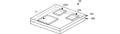
- the communication module 1 is realized by the circuit configuration as described above. Although the communication module 1 has been partially described in the above description, as illustrated in FIG. 3, the circuit illustrated in FIG. 1 is mechanically realized from the stacked body 900 and the mounting element.
- the laminated body 900 is formed by laminating a predetermined number of dielectric layers on which internal electrode patterns are formed. The internal electrode pattern and the via-hole electrode connecting the layers realize a circuit configuration other than the mounted element.
- mounted elements for realizing the control IC 20, the power amplifier 11 constituting the transmission module 10, and the individual isolators 120 ⁇ / b> L and 120 ⁇ / b> H are mounted.
- achieves the duplexers 40L and 40H and the switch elements 30 and 50 is also mounted.
- the top surface of the laminate 900 on which these mounting elements are mounted is covered with a resin 901 to protect the top surface and each mounting element from the external environment.
- the transmission module 1 includes a power amplifier 11, a low-pass (low-pass) filter 13, and a multiband isolator 12.
- the first transmission signal or the second transmission signal from the input end TXin of the transmission module 10, that is, from the switch element 30 is input to the power amplifier 11.
- the power amplifier 11 amplifies and outputs the first transmission signal or the second transmission signal.
- the power amplifier 11 has an output impedance of several ⁇ (for example, about 5 ⁇ ). By setting such a low output impedance, the final stage FET can be made small. For this reason, the power amplifier 11 can be reduced in size, and the transmission module 10 can also be reduced in size.
- the single input terminal of the multiband isolator 12 is connected to the output terminal of the power amplifier 11 via the impedance conversion circuit 13.
- the impedance conversion circuit 13 includes an inductor L0 connected between the output terminal of the power amplifier 11 and a single input terminal of the multiband isolator 12, and the end of the inductor L0 on the multiband isolator 12 side to the ground potential. It consists of a capacitor C0 to be connected.
- the impedance conversion circuit 13 appropriately sets the inductance of the inductor L0 and the capacitance of the capacitor C0, so that a low-pass filter function having at least a higher frequency band than the frequency band of the second transmission signal as an attenuation band. May be set to have In other words, the element value may be set so as to attenuate high-order harmonics of the transmission signal on the high frequency side.
- FIG. 4 is a Smith chart when the low-pass filter 13 side is viewed from the output terminal of the power amplifier 11.
- FIG. 5 is a Smith chart when the input terminal side of the multiband isolator 12 is viewed from the output end of the low-pass filter 13.
- both the frequency band of the first transmission signal and the frequency band of the second transmission signal are about 5 ⁇ . It is set so as to be impedance-converted.
- the impedance conversion circuit 13 sees the input terminal side of the multiband isolator 12 from the output end of the impedance conversion circuit 13, it remains about 5 ⁇ in the frequency band of the first transmission signal.
- the frequency band of the second transmission signal is set to be about 25 ⁇ .
- the impedance conversion circuit 13 has a function of converting impedance from several ohms (about 5 ohms) to about 25 ohms for the second transmission signals while hardly producing an impedance conversion function for the first transmission signals. .
- the multiband isolator 12 is a 1-input 2-output isolator and includes an individual isolator 120L corresponding to the first transmission signal and an individual isolator 120H corresponding to the second transmission signal.
- the single input terminal as the multi-band isolator 12 is directly connected to the input terminal of the individual isolator 120H, and is connected to the input terminal of the individual isolator 120L via the second impedance conversion circuit 121. is doing.
- the two output terminals of the multiband isolator 12 that is, the two output terminals TXoutL and TXoutH of the transmission module are connected to the output terminals of the individual isolators 120L and 120H, respectively.
- the impedance conversion circuit 121 includes an inductor L1 connected between a single input terminal of the multiband isolator 12 and an input end of the individual isolator 120L, and capacitors C11 and C12 that connect both ends of the inductor L1 to the ground potential. And is realized by a ⁇ -type circuit.
- the impedance conversion circuit 121 sets the element values of the inductor L1 and the capacitors C11 and C12 as appropriate, thereby setting the frequency band of the first transmission signal as the pass band and including the frequency band of the second transmission signal. It has the characteristic of attenuating the frequency band side. Thus, only the first transmission signal is input to the individual isolator 120L, and the second transmission signal is not input.
- the impedance conversion circuit 121 sets the element values of the inductor L1 and the capacitors C11 and C12 as appropriate based on the same principle as that of the impedance conversion circuit 13 described above, so that it is several ⁇ (about 5 ⁇ ) with respect to the first transmission signal. Functions as a circuit that converts the impedance from 1 to about 25 ⁇ .
- the individual isolator 120L is a permanent magnet that sandwiches a ferrite core, an electrode pattern disposed with respect to the ferrite core, and a core member composed of the ferrite core and the electrode pattern.
- the main component is an isolator element 1201L formed only from the above.
- the shape of the core member of the isolator element 1201L is set so that only the frequency band of the first transmission signal is transmitted from the input end to the output end with low loss.
- the input terminal of the isolator element 1201L is connected to the ground potential by the capacitor Cm.
- the capacitor Cm functions as a circuit that performs impedance conversion from about 25 ⁇ to about 50 ⁇ with respect to the first transmission signal by appropriately setting the capacitance.
- the individual isolator 120H is a permanent magnet that sandwiches a ferrite core, an electrode pattern disposed with respect to the ferrite core, and a core member composed of the ferrite core and the electrode pattern.
- the main component is an isolator element 1201H formed only from the above.
- the shape of the core member of the isolator element 1201H is set so that the loss is transmitted from the input end to the output end only with respect to the frequency band of the second transmission signal.
- the input end of the isolator element 1201H is connected to the ground potential by the inductor Lm.
- the inductor Lm functions as a circuit that converts the impedance of the second transmission signal from about 25 ⁇ to about 50 ⁇ by appropriately setting the inductance.
- the first transmission signal is amplified by the power amplifier 11 from the input terminal TXin of the transmission module 10, and passes through the individual isolator 120 ⁇ / b> L via the impedance conversion circuits 13 and 121. And output from the output terminal TXoutL.
- impedance conversion is performed by the impedance conversion circuits 13 and 121 and the matching circuit of the input stage of the individual isolator 120L, even if the output impedance of the power amplifier 11 and the input impedance of the isolator element 1201L are different, the impedance is surely low. Loss impedance matching becomes possible. As a result, the first transmission signal can be output with low loss.
- the impedance conversion is gradually performed in three stages of the impedance conversion circuits 13 and 121 and the matching circuit of the input stage of the individual isolator 120L, so that a sudden impedance change due to a single impedance conversion is performed. Compared with matching, impedance matching with low loss can be performed more accurately.
- the second transmission signal is amplified by the power amplifier 11 from the input terminal TXin of the transmission module 10, and passes through the individual isolator 120 ⁇ / b> H via the impedance conversion circuit 13. And output from the output terminal TXoutH.
- impedance conversion is performed by the impedance conversion circuit 13 and the matching circuit of the input stage of the individual isolator 120H, even if the output impedance of the power amplifier 11 and the input impedance of the isolator element 1201H are different, reliable and low loss is achieved. Impedance matching becomes possible. As a result, the second transmission signal can be output with low loss.
- a multiband transmission module that amplifies a plurality of transmission signals of different frequency bands and outputs them from individual output terminals with almost no loss is realized. can do.
- the inductors and capacitors constituting the impedance conversion circuits 13 and 121 described above can be realized by mounted elements.
- the inductors L0 and L1 are formed by using the inner layer electrode pattern of the multilayer body 900 and the top of the multilayer body 900. It can also be realized by a surface electrode pattern or a wire electrode (linear electrode) mounted on the top surface of the laminate 900. If these configurations are used, it is not necessary to prepare the inductors L0 and L1 as individual mounted elements, and thus the transmission module 10 can be downsized.
- a WCDMA850 communication signal or a WCDMA900 communication signal is used as a low-frequency communication signal
- a WCDMA1800 communication signal or a WCDMA1900 communication signal is used as a high-frequency communication signal.
- WCDMA 850 is used as a communication signal on the low frequency side
- a communication signal of WCDMA 950 is used as a communication signal on the high frequency side.
- the above-described configuration is used, the more effective the frequency band of the communication signal on the low frequency side and the frequency band of the communication signal on the high frequency side are, the more effective.
- the above-described configuration can be applied not only to WCDMA communication signals but also to other communication signals.
- the multi-band isolator having one input and two outputs has been described as an example.
Landscapes
- Engineering & Computer Science (AREA)
- Computer Networks & Wireless Communication (AREA)
- Signal Processing (AREA)
- Transceivers (AREA)
- Transmitters (AREA)
Abstract
スイッチ素子による損失を防止し、複数種類の送信信号を増幅して、より低損失に出力できるマルチバンドの送信モジュールを実現する。送信モジュール(10)は、パワーアンプ(11)およびマルチバンドアイソレータ(12)を備える。パワーアンプ(11)の出力端は、低域通過フィルタ機能を有するインピーダンス変換回路(13)を介してマルチバンドアイソレータ(12)の単一の入力端子へ接続している。マルチバンドアイソレータ(12)は、低周波数用の個別アイソレータ(120L)と、高周波数用の個別アイソレータ(120H)とを備える。個別アイソレータ(120H)の入力端は、マルチバンドアイソレータ(12)の単一の入力端子に直接接続し、個別アイソレータ(120L)の入力端は、マルチバンドアイソレータ(12)の単一の入力端子に対して低域通過フィルタ機能を有するインピーダンス変換回路(121)を介して接続している。
Description
本発明は、送信信号を増幅して出力する送信モジュール、特に、複数の周波数帯域の送信信号を増幅して出力可能なマルチバンドの送信モジュールに関する。
携帯電話機等に搭載されている無線通信モジュールは、送信信号を生成してアンテナへ出力する送信回路と、アンテナで受信した信号を増幅する受信回路とが備えられている。特に、現在マルチバンド対応の無線通信モジュールが要求されており、送信回路としては、それぞれに異なる周波数の送信信号を生成し、アンテナへ供給する必要がある。このため、特許文献1には、複数種類の送信信号を生成する送信信号発生器と、送信信号発生器からの送信信号を増幅するパワーアンプ(PA)と、PAから出力される送信信号を切り替えて、送信信号の種類毎に設けられたデュプレクサへ出力するスイッチ素子と、を備えた送信装置が開示されている。
しかしながら、特許文献1に示すような送信装置(送信回路)では、PAによって増幅された送信信号を、スイッチ素子で切り替えて出力する構造となるため、当該スイッチ素子で発生する損失により、送信信号が不要に減衰してしまう。
したがって、本発明の目的は、スイッチ素子による損失を防止し、複数種類の送信信号を増幅して、より低損失に出力できるマルチバンドの送信モジュールを実現することにある。
この発明は、送信信号を増幅して出力する送信モジュールに関する。本発明の送信モジュールは、パワーアンプとマルチバンドアイソレータと低域通過フィルタ型のインピーダンス変換回路とを備える。パワーアンプは、異なる周波数帯域を利用した複数の送信信号を増幅する。マルチバンドアイソレータは、該パワーアンプの出力端に接続し、単一の入力端子に対して、複数の送信信号毎に異なる出力端子を備え、入力端子と出力端子との間にそれぞれ接続された複数の個別アイソレータを備える。低域通過フィルタ型のインピーダンス変換回路は、インダクタおよびキャパシタを組み合わせて回路構成され、パワーアンプの出力端とマルチバンドアイソレータの単一の入力端子との間に接続されている。
この構成では、パワーアンプから出力された各周波数帯域の送信信号は、それぞれの送信信号に対応した個別アイソレータを通過して、個別の出力端子から出力される。この際、パワーアンプとマルチバンドアイソレータとの間に接続された低域通過フィルタ型のインピーダンス変換回路によりインピーダンス整合がされ、マルチバンドアイソレータでの伝送損失が低減される。これにより、従来の構成のようなスイッチ素子による損失は生じず、且つ伝送損失が低くなり、送信モジュールとしての伝送損失が従来よりも大幅に低減される。
また、この発明の送信モジュールでは、マルチバンドアイソレータの単一の入力端子と個別アイソレータの入力側との間に、それぞれに個別のインピーダンス変換回路を備えている、ことが好ましい。
この構成では、個別アイソレータの入力側に、さらにインピーダンス変換回路が備えられるので、段階的なインピーダンス整合が可能になる。これにより、一度で大幅なインピーダンス変換を行う場合よりも低損失なインピーダンス変換が可能になり、さらに伝送損失を低減することができる。
また、この発明の送信モジュールでは、個別のインピーダンス変換回路は、個別アイソレータの入力側の伝送線路とグランド電位との間に接続されたインダクタもしくはキャパシタにより構成されている、ことが好ましい。
この構成では、個別アイソレータの入力側にそれぞれ挿入される個別のインピーダンス変換回路を、簡素な構成で実現できる。これにより、送信モジュールを大型化することなく、インピーダンス不整合による損失を大幅に抑制する構成を実現できる。
また、この発明の送信モジュールでは、次の構成であることが好ましい。マルチバンドアイソレータは、高周波数帯域用の個別アイソレータと、低周波数帯域用の個別アイソレータとで構成される。低周波数帯域用の個別アイソレータの入力側に、高周波数帯域を減衰帯域内とする第2の低域通過フィルタ型のインピーダンス変換回路を備える。
この構成では、第2の低域通過フィルタ型のインピーダンス変換回路において、高周波数帯域の送信信号が減衰されて、低周波数帯域用の個別アイソレータに入力されない。また、パワーアンプと低周波数帯域用の個別アイソレータとの間のインピーダンス整合の段階を増加させることができる。これにより、さらに伝送特性に優れる送信モジュールを実現できる。
また、この発明の送信モジュールでは、次のいずれかの態様であることが好ましい。
・低域通過フィルタ型のインピーダンス変換回路を構成するインダクタを、送信モジュールを形成する積層体に形成された電極パターンもしくは積層体に実装された線状電極により形成する。
・第2の低域通過フィルタ型のインピーダンス変換回路を構成するインダクタを、送信モジュールを形成する積層体に形成された電極パターンもしくは積層体に実装された線状電極により形成する。
・低域通過フィルタ型のインピーダンス変換回路および第2の低域通過フィルタ型のインピーダンス変換回路を構成する各インダクタを、送信モジュールを形成する積層体に形成された電極パターンもしくは積層体に実装された線状電極により形成する。
これらの構成は、低域通過フィルタ型のインピーダンス変換回路および第2の低域通過フィルタ型のインピーダンス変換回路の少なくとも一方のインダクタを、具体的に実現する構造の例を示している。このような構造とすることで、低域通過フィルタ型のインピーダンス変換回路および第2の低域通過フィルタ型のインピーダンス変換回路のインダクタを、単独の独立した素子で実現する必要がなく、送信モジュールを小型化できる。
この発明によれば、複数種類の送信信号を増幅して、殆ど損失を生じさせることなく出力するマルチバンドの送信モジュールを実現することができる。
本発明の実施形態に係る送信モジュール10について、図を参照して説明する。なお、本実施形態では、低周波数側の通信信号としてWCDMA850の通信信号もしくはWCDMA900の通信信号を用い、高周波数側の通信信号としてWCDMA1800の通信信号もしくはWCDMA1900の通信信号を用いる場合を示す。
図1は本実施形態に係る送信モジュール10を含む通信モジュール1の回路構成図である。図2は本実施形態に係る送信モジュール10の回路構成および各部のインピーダンスを示す図である。図3は本実施形態に係る通信モジュール1の外観斜視図である。なお、図3では本実施形態における主要な実装型素子のみを記載し、それ以外の実装型素子(例えばスイッチ素子、デュプレクサ、実装型インダクタ、実装型キャパシタ等)については図示を省略している。
送信モジュール10は、図1、図2に示すような通信モジュール1に備えられる。通信モジュール1は、送信モジュール10、コントロールIC20、スイッチ素子30、デュプレクサ40H,40L、スイッチ素子50を備える。
コントロールIC20は、ベースバンドIC21およびRFIC22を備える。これらは、各周波数の送信信号、具体的には低周波数側通信の送信信号(第1送信信号)および高周波数側通信の送信信号(第2送信信号)を生成する。また、コントロールIC20は、デュプレクサ40H,40Lから出力された低周波数側通信の受信信号(第1受信信号)および高周波数側通信の受信信号(第2受信信号)を出力したり、復調したりする。また、コントロールIC20は、スイッチ素子30,50のスイッチング制御も行う。通信モジュール1は、例えばプリント基板などのマザー基板上に通信モジュール10や他の部品が実装されて構成され、コントロールIC20は、マザー基板上に実装される実装型ICで実現される。
コントロールIC20のRFIC22から出力された第1送信信号もしくは第2送信信号は、スイッチ素子30へ出力される。スイッチ素子30は、第1送信信号もしくは第2送信信号のいずれかを、スイッチング制御に応じて送信モジュール10の入力端TXinへ出力する。
送信モジュール10は、詳細な構成は後述するが、入力端TXinから入力された第1送信信号を増幅して、低周波数側出力端TXoutLから出力し、入力端TXinから入力された第2送信信号を増幅して、高周波数側出力端TXoutHから出力する。低周波数側出力端TXoutLから出力された第1送信信号は、デュプレクサ40Lの共通端子へ入力される。高周波数側出力端TXoutHから出力された第2送信信号は、デュプレクサ40Hの共通端子へ入力される。
デュプレクサ40Lは、例えばSAWデュプレクサによって実現され、送信側SAWフィルタと受信側SAWフィルタとから構成される。デュプレクサ40Lの送信側SAWフィルタは、第1送信信号の周波数帯域を通過帯域とし、第1受信信号の周波数帯域を含む他の周波数帯域を減衰帯域とするフィルタである。デュプレクサ40Lの受信側SAWフィルタは、第1受信信号の周波数帯域を通過帯域とし、第1送信信号の周波数帯域を含む他の周波数帯域を減衰帯域とするフィルタである。
デュプレクサ40Lの共通端子へ入力された第1送信信号は、送信側SAWフィルタを介してスイッチ素子50へ出力される。スイッチ素子50からの第1受信信号は、受信側SAWフィルタを通過して、コントロールIC20のRFIC22へ出力される。
デュプレクサ40Hも、通過帯域が異なるだけで、基本構成はデュプレクサ40Lと同じである。デュプレクサ40Hの共通端子へ入力された第2送信信号は、送信側SAWフィルタを介してスイッチ素子50へ出力される。スイッチ素子50からの第2受信信号は、受信側SAWフィルタを通過して、コントロールIC20のRFIC22へ出力される。
スイッチ素子50は、デュプレクサ40H,40Lに接続する個別端子と、外部のアンテナANTに接続する共通端子とを備え、スイッチ制御に基づいて、個別端子のいずれかを共通端子へ接続する。具体的には、低周波数側通信の送受信を行う場合には、デュプレクサ40LとアンテナANTを接続するように、低周波数通信用の個別端子と共通端子を接続する。高周波数側通信の送受信を行う場合には、デュプレクサ40HとアンテナANTを接続するように、高周波数通信用の個別端子と共通端子を接続する。
以上のような回路構成により、通信モジュール1が実現される。なお、当該通信モジュール1は、上述の説明で部分的に説明したが、図3に示すように、積層体900と実装型素子とから、図1に示す回路を機構的に実現している。積層体900は内部電極パターンが形成された誘電体層を所定層積層してなる。この内部電極パターンおよび層間を接続するビアホール電極により、実装型素子以外の回路構成を実現している。積層体900の天面には、コントロールIC20と、送信モジュール10を構成するパワーアンプ11、個別アイソレータ120L,120Hと、をそれぞれに実現する実装型素子が実装されている。また、図示しないが、デュプレクサ40L,40Hやスイッチ素子30,50を実現する実装型素子も実装されている。そして、これら実装型素子が実装された積層体900の天面は樹脂901により覆われており、天面および各実装型素子を外部環境から保護している。
次に、送信モジュール1の具体的構成および機能について説明する。
図2に示すように、送信モジュール1は、パワーアンプ11、ローパス(低域通過)フィルタ13、マルチバンドアイソレータ12を備える。送信モジュール10の入力端TXinからの、すなわちスイッチ素子30からの第1送信信号または第2送信信号は、パワーアンプ11に入力される。
パワーアンプ11は、第1送信信号または第2送信信号を、増幅して出力する。当該パワーアンプ11は、出力インピーダンスが数Ω(例えば5Ω程度)である。このような低出力インピーダンスに設定することで、最終段のFETを小さくすることができる。このため、パワーアンプ11を小型化でき、ひいては送信モジュール10も小型化できる。
パワーアンプ11の出力端には、インピーダンス変換回路13を介して、マルチバンドアイソレータ12の単一の入力端子が接続されている。
インピーダンス変換回路13は、パワーアンプ11の出力端とマルチバンドアイソレータ12の単一の入力端子との間に接続されたインダクタL0と、該インダクタL0のマルチバンドアイソレータ12側の端部をグランド電位へ接続するキャパシタC0とからなる。
この際、インピーダンス変換回路13は、インダクタL0のインダクタンスおよびキャパシタC0のキャパシタンスを適宜設定することで、少なくとも第2送信信号の周波数帯域よりも高周波数側の帯域を減衰帯域とする低域通過フィルタ機能を有するように、設定されてもよい。言い換えれば、高周波数側の送信信号の高次高調波を減衰させるような素子値の設定がされていてもよい。
また、インピーダンス変換回路13は、図4、図5に示すような反射特性が得られるように、設定されている。図4はパワーアンプ11の出力端からローパスフィルタ13側を見た時のスミスチャートである。図5はローパスフィルタ13の出力端からマルチバンドアイソレータ12の入力端子側を見た時のスミスチャートである。
図4に示すように、インピーダンス変換回路13は、パワーアンプ11の出力端からインピーダンス変換回路13側を見ると、第1送信信号の周波数帯域も、第2送信信号の周波数帯域もともに、5Ω程度にインピーダンス変換されるように設定されている。
また、図5に示すように、インピーダンス変換回路13は、インピーダンス変換回路13の出力端からマルチバンドアイソレータ12の入力端子側を見ると、第1送信信号の周波数帯域では5Ω程度のままであり、第2送信信号の周波数帯域では25Ω程度になるように設定されている。
このように、インピーダンス変換回路13は、第1送信信号に対してはインピーダンス変換機能を殆ど生じず、第2送信信号に対しては数Ω(約5Ω)から約25Ωにインピーダンス変換する機能を備える。
マルチバンドアイソレータ12は、1入力2出力のアイソレータであり、第1送信信号に対応した個別アイソレータ120Lと、第2送信信号に対応した個別アイソレータ120Hとを備える。
マルチバンドアイソレータ12としての単一の入力端子は、個別アイソレータ120Hの入力端に対しては直接接続するとともに、個別アイソレータ120Lの入力端に対しては、第2のインピーダンス変換回路121を介して接続している。
マルチバンドアイソレータ12の二つの出力端子すなわち送信モジュールの二つの出力端子TXoutL,TXoutHは、それぞれに個別アイソレータ120L,120Hの出力端に接続している。
インピーダンス変換回路121は、マルチバンドアイソレータ12の単一の入力端子と個別アイソレータ120Lの入力端との間に接続されたインダクタL1と、該インダクタL1の両端をそれぞれグランド電位に接続するキャパシタC11,C12と、からなるπ型の回路で実現される。
インピーダンス変換回路121は、インダクタL1、キャパシタC11,C12の素子値を適宜設定することで、第1送信信号の周波数帯域を通過帯域として、第2送信信号の周波数帯域を含む、当該通過帯域の高周波数帯側を減衰する特性を有する。これにより、個別アイソレータ120Lには、第1送信信号のみが入力され、第2送信信号は入力されない。
また、インピーダンス変換回路121は、上述のインピーダンス変換回路13と同様の原理により、インダクタL1、キャパシタC11,C12の素子値を適宜設定することで、第1送信信号に対して数Ω(約5Ω)から約25Ωにインピーダンス変換する回路として機能する。
個別アイソレータ120Lは、例えば特開2006-311455に示すように、フェライトコアと、当該フェライトコアに対して配設された電極パターンと、これらフェライトコアおよび電極パターンからなるコア部材を狭持する永久磁石とのみから形成されるアイソレータ素子1201Lを主体とする。この際、アイソレータ素子1201Lは、第1送信信号の周波数帯域に対してのみ、入力端から出力端へ低損失に伝送するように、コア部材の形状が設定されている。
アイソレータ素子1201Lの入力端は、キャパシタCmによりグランド電位に接続されている。このキャパシタCmは、キャパシタンスを適宜設定することで、第1送信信号に対して約25Ωから約50Ωにインピーダンス変換する回路として機能する。
個別アイソレータ120Hは、例えば特開2006-311455に示すように、フェライトコアと、当該フェライトコアに対して配設された電極パターンと、これらフェライトコアおよび電極パターンからなるコア部材を狭持する永久磁石とのみから形成されるアイソレータ素子1201Hを主体とする。この際、アイソレータ素子1201Hは、第2送信信号の周波数帯域に対してのみ、入力端から出力端へ低損失に伝送するように、コア部材の形状が設定されている。
アイソレータ素子1201Hの入力端は、インダクタLmによりグランド電位に接続されている。このインダクタLmは、インダクタンスを適宜設定することで、第2送信信号に対して約25Ωから約50Ωにインピーダンス変換する回路として機能する。
このような構成とすることで、送信モジュール10では、第1送信信号は、送信モジュール10の入力端子TXinからパワーアンプ11で増幅され、インピーダンス変換回路13,121を介し、個別アイソレータ120Lを通過して出力端子TXoutLから出力される。この際、インピーダンス変換回路13,121、および個別アイソレータ120Lの入力段の整合回路でインピーダンス変換されるので、パワーアンプ11の出力インピーダンスと、アイソレータ素子1201Lの入力インピーダンスが異なっていても、確実且つ低損失なインピーダンス整合が可能になる。これにより、第1送信信号を低損失で出力することができる。
さらに、上述のように、インピーダンス変換回路13,121、および個別アイソレータ120Lの入力段の整合回路の三段階で徐々にインピーダンス変換していくことで、一回のインピーダンス変換による急激なインピーダンスの変化による整合と比較して、より正確に低損失なインピーダンス整合が可能になる。
また、このような構成とすることで、送信モジュール10では、第2送信信号は、送信モジュール10の入力端子TXinからパワーアンプ11で増幅され、インピーダンス変換回路13を介し、個別アイソレータ120Hを通過して出力端子TXoutHから出力される。この際、インピーダンス変換回路13、および個別アイソレータ120Hの入力段の整合回路でインピーダンス変換されるので、パワーアンプ11の出力インピーダンスと、アイソレータ素子1201Hの入力インピーダンスが異なっていても、確実且つ低損失なインピーダンス整合が可能になる。これにより、第2送信信号を低損失で出力することができる。
さらに、上述のように、インピーダンス変換回路13および個別アイソレータ120Lの入力段の整合回路の二段階で徐々にインピーダンス変換していくことで、一回のインピーダンス変換による急激なインピーダンスの変化による整合と比較して、より正確に低損失なインピーダンス整合が可能になる。
以上のように、本実施形態の構成を用いることで、それぞれ異なる周波数帯域の複数の送信信号を増幅して、殆ど損失を生じさせることなく個別の出力端子から出力するマルチバンドの送信モジュールを実現することができる。
なお、上述のインピーダンス変換回路13,121を構成するインダクタやキャパシタは、実装型素子で実現することができるが、例えば、インダクタL0、L1を、積層体900の内層電極パターン、積層体900の天面の電極パターン、積層体900の天面に実装されたワイヤ電極(線状電極)で実現することもできる。これら構成を用いれば、インダクタL0,L1を個別の実装型素子で用意する必要がないので、送信モジュール10の小型化が可能になる。
なお、上述の実施形態では、低周波数側の通信信号としてWCDMA850の通信信号もしくはWCDMA900の通信信号を用い、高周波数側の通信信号としてWCDMA1800の通信信号もしくはWCDMA1900の通信信号を用いる例を示したが、低周波数側の通信信号としてWCDMA850を用い、高周波数側の通信信号としてWCDMA950の通信信号を用いるような構成に利用することもできる。ただし、上述の構成を用いる場合、低周波数側の通信信号の周波数帯域と高周波数側の通信信号の周波数帯域とが離間しているほど、より有効となる。また、WCDMA系の通信信号のみでなく、他の通信信号に対しても同様に、上述の構成を適用することができる。
また、上述の実施形態では、一入力二出力のマルチバンドアイソレータを例に説明したが、N=2以上の整数とし、一入力N出力のマルチバンドアイソレータに対しても、上述の構成を適用することができる。
1:通信モジュール、10:送信モジュール、11:パワーアンプ、12:マルチバンドアイソレータ、13:インピーダンス変換回路、20:コントロールIC、21:ベースバンドIC、22:RFIC、30,50:スイッチ素子、40H,40L:デュプレクサ、120L,120H:個別アイソレータ、121:インピーダンス変換回路、1201L,1201H:アイソレータ素子
Claims (7)
- 異なる周波数帯域を利用した複数の送信信号を増幅するパワーアンプと、
該パワーアンプの出力端に接続し、単一の入力端子に対して、前記複数の送信信号毎に異なる出力端子を備え、前記入力端子と前記出力端子との間にそれぞれ個別アイソレータが接続されたマルチバンドアイソレータと、
前記パワーアンプの出力端と前記マルチバンドアイソレータの前記単一の入力端子との間に、インダクタおよびキャパシタを組み合わせてなる低域通過フィルタ型のインピーダンス変換回路を備えた、送信モジュール。 - 請求項1に記載の送信モジュールであって、
前記マルチバンドアイソレータの前記単一の入力端子と前記個別アイソレータの入力側との間に、それぞれに個別のインピーダンス変換回路を備えた、送信モジュール。 - 請求項2に記載の送信モジュールであって、
前記個別のインピーダンス変換回路は、前記個別アイソレータの入力側の伝送線路とグランド電位との間に接続されたインダクタもしくはキャパシタにより構成されている、送信モジュール。 - 請求項1乃至請求項3のいずれかに記載の送信モジュールであって、
前記マルチバンドアイソレータは、高周波数帯域用の個別アイソレータと、低周波数帯域用の個別アイソレータとで構成され、
前記低周波数帯域用の個別アイソレータの入力側に、前記高周波数帯域を減衰帯域内とする第2の低域通過フィルタ型のインピーダンス変換回路を備える、送信モジュール。 - 請求項1乃至請求項4のいずれかに記載の送信モジュールであって、
前記低域通過フィルタ型の整合回路を構成するインダクタは、前記送信モジュールを形成する積層体に形成された電極パターンもしくは前記積層体に実装された線状電極により形成される、送信モジュール。 - 請求項4に記載の送信モジュールであって、
前記第2の低域通過フィルタ型のインピーダンス変換回路を構成するインダクタは、前記送信モジュールを形成する積層体に形成された電極パターンもしくは前記積層体に実装された線状電極により形成される、送信モジュール。 - 請求項4に記載の送信モジュールであって、
前記低域通過フィルタ型のインピーダンス変換回路および前記第2の低域通過フィルタ型のインピーダンス変換回路を構成する各インダクタは、前記送信モジュールを形成する積層体に形成された電極パターンもしくは前記積層体に実装された線状電極により形成される、送信モジュール。
Applications Claiming Priority (2)
| Application Number | Priority Date | Filing Date | Title |
|---|---|---|---|
| JP2011015892 | 2011-01-28 | ||
| JP2011-015892 | 2011-01-28 |
Publications (1)
| Publication Number | Publication Date |
|---|---|
| WO2012102285A1 true WO2012102285A1 (ja) | 2012-08-02 |
Family
ID=46580850
Family Applications (1)
| Application Number | Title | Priority Date | Filing Date |
|---|---|---|---|
| PCT/JP2012/051496 WO2012102285A1 (ja) | 2011-01-28 | 2012-01-25 | 送信モジュール |
Country Status (1)
| Country | Link |
|---|---|
| WO (1) | WO2012102285A1 (ja) |
Citations (2)
| Publication number | Priority date | Publication date | Assignee | Title |
|---|---|---|---|---|
| JPH07283615A (ja) * | 1994-04-07 | 1995-10-27 | Matsushita Electric Ind Co Ltd | 非可逆回路装置 |
| JP2007329669A (ja) * | 2006-06-07 | 2007-12-20 | Murata Mfg Co Ltd | 電力増幅装置 |
-
2012
- 2012-01-25 WO PCT/JP2012/051496 patent/WO2012102285A1/ja active Application Filing
Patent Citations (2)
| Publication number | Priority date | Publication date | Assignee | Title |
|---|---|---|---|---|
| JPH07283615A (ja) * | 1994-04-07 | 1995-10-27 | Matsushita Electric Ind Co Ltd | 非可逆回路装置 |
| JP2007329669A (ja) * | 2006-06-07 | 2007-12-20 | Murata Mfg Co Ltd | 電力増幅装置 |
Similar Documents
| Publication | Publication Date | Title |
|---|---|---|
| JP5569571B2 (ja) | 分波回路及び高周波モジュール | |
| JP4466788B2 (ja) | 高周波スイッチモジュール | |
| WO2017033564A1 (ja) | 高周波モジュール | |
| JP2012505580A (ja) | 平面アンテナ用のインピーダンス整合回路 | |
| JP5837045B2 (ja) | 高周波スイッチモジュール | |
| WO2018123972A1 (ja) | 高周波モジュール及び通信装置 | |
| JP5387510B2 (ja) | 高周波スイッチモジュール | |
| JP5773251B2 (ja) | 高周波回路、高周波部品およびそれらを用いた通信装置 | |
| US10027008B2 (en) | Irreversible circuit element and module | |
| WO2012102284A1 (ja) | 送信モジュール | |
| JP6662349B2 (ja) | 方向性結合器、高周波フロントエンドモジュール、および、通信機器 | |
| JP5304811B2 (ja) | 高周波モジュール | |
| WO2002054591A1 (fr) | Filtre passe-bas haute frequence | |
| WO2022034824A1 (ja) | 高周波回路及び通信装置 | |
| US9088064B2 (en) | Non-reciprocal circuit element | |
| WO2010044373A1 (ja) | Lcフィルタおよび高周波スイッチモジュール | |
| WO2012102285A1 (ja) | 送信モジュール | |
| JP2007110271A (ja) | 平衡−不平衡変換回路及びこれを用いた高周波部品 | |
| CN101257286B (zh) | 具有∏型网络电路的天线多工器及∏型网络电路的应用 | |
| WO2013108677A1 (ja) | 電力増幅回路 | |
| WO2018180150A1 (ja) | トラップフィルタおよびフィルタ回路 | |
| CN106936464A (zh) | 通信设备以及包括在其中的前端模块 | |
| JP2008034980A (ja) | 複合高周波部品 |
Legal Events
| Date | Code | Title | Description |
|---|---|---|---|
| 121 | Ep: the epo has been informed by wipo that ep was designated in this application |
Ref document number: 12739154 Country of ref document: EP Kind code of ref document: A1 |
|
| NENP | Non-entry into the national phase |
Ref country code: DE |
|
| 122 | Ep: pct application non-entry in european phase |
Ref document number: 12739154 Country of ref document: EP Kind code of ref document: A1 |
|
| NENP | Non-entry into the national phase |
Ref country code: JP |