WO2012102227A1 - 面状照明装置、および、それを備えた電子機器、並びに液晶表示装置 - Google Patents
面状照明装置、および、それを備えた電子機器、並びに液晶表示装置 Download PDFInfo
- Publication number
- WO2012102227A1 WO2012102227A1 PCT/JP2012/051315 JP2012051315W WO2012102227A1 WO 2012102227 A1 WO2012102227 A1 WO 2012102227A1 JP 2012051315 W JP2012051315 W JP 2012051315W WO 2012102227 A1 WO2012102227 A1 WO 2012102227A1
- Authority
- WO
- WIPO (PCT)
- Prior art keywords
- light
- light guide
- guide portion
- guide plate
- light emitting
- Prior art date
- Legal status (The legal status is an assumption and is not a legal conclusion. Google has not performed a legal analysis and makes no representation as to the accuracy of the status listed.)
- Ceased
Links
Images









Classifications
-
- G—PHYSICS
- G02—OPTICS
- G02B—OPTICAL ELEMENTS, SYSTEMS OR APPARATUS
- G02B6/00—Light guides; Structural details of arrangements comprising light guides and other optical elements, e.g. couplings
- G02B6/0001—Light guides; Structural details of arrangements comprising light guides and other optical elements, e.g. couplings specially adapted for lighting devices or systems
- G02B6/0011—Light guides; Structural details of arrangements comprising light guides and other optical elements, e.g. couplings specially adapted for lighting devices or systems the light guides being planar or of plate-like form
- G02B6/0033—Means for improving the coupling-out of light from the light guide
- G02B6/0058—Means for improving the coupling-out of light from the light guide varying in density, size, shape or depth along the light guide
- G02B6/0061—Means for improving the coupling-out of light from the light guide varying in density, size, shape or depth along the light guide to provide homogeneous light output intensity
-
- G—PHYSICS
- G02—OPTICS
- G02B—OPTICAL ELEMENTS, SYSTEMS OR APPARATUS
- G02B6/00—Light guides; Structural details of arrangements comprising light guides and other optical elements, e.g. couplings
- G02B6/0001—Light guides; Structural details of arrangements comprising light guides and other optical elements, e.g. couplings specially adapted for lighting devices or systems
- G02B6/0011—Light guides; Structural details of arrangements comprising light guides and other optical elements, e.g. couplings specially adapted for lighting devices or systems the light guides being planar or of plate-like form
- G02B6/0033—Means for improving the coupling-out of light from the light guide
- G02B6/0035—Means for improving the coupling-out of light from the light guide provided on the surface of the light guide or in the bulk of it
- G02B6/0045—Means for improving the coupling-out of light from the light guide provided on the surface of the light guide or in the bulk of it by shaping at least a portion of the light guide
- G02B6/0046—Tapered light guide, e.g. wedge-shaped light guide
-
- G—PHYSICS
- G02—OPTICS
- G02B—OPTICAL ELEMENTS, SYSTEMS OR APPARATUS
- G02B6/00—Light guides; Structural details of arrangements comprising light guides and other optical elements, e.g. couplings
- G02B6/0001—Light guides; Structural details of arrangements comprising light guides and other optical elements, e.g. couplings specially adapted for lighting devices or systems
- G02B6/0011—Light guides; Structural details of arrangements comprising light guides and other optical elements, e.g. couplings specially adapted for lighting devices or systems the light guides being planar or of plate-like form
- G02B6/0075—Arrangements of multiple light guides
- G02B6/0078—Side-by-side arrangements, e.g. for large area displays
Definitions
- the present invention relates to a planar illumination device that emits light from a light source in a planar shape by a light guide plate, and an electronic device such as a liquid crystal display device including the planar illumination device.
- a backlight having a side edge (also referred to as sidelight) type light guide plate that emits light from a light source in a planar shape by the light guide plate is frequently used.
- the light guide plate is divided into a plurality of areas, a light source is associated with each divided area, and light is emitted from only the corresponding divided area (light emitting area) by emitting a desired light source.
- area control By such area control, pseudo-impulse type display is realized, or light transmittance is controlled in the liquid crystal layer of the liquid crystal display element, and brightness adjustment of a specific area is also performed in the backlight, thereby improving display quality. It can be improved.
- Patent Document 1 discloses an illumination device that realizes area control of a light guide plate.
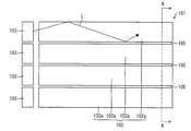
- FIG. 16 is a plan view of the illumination device of Patent Document 1.
- FIG. FIG. 17 is a cross-sectional view taken along line AA ′ shown in FIG. 16 and 17, the light guide plate 102 including a plurality of blocks 102a arranged in a row, and a plurality of light sources 103 provided for each block 102a and irradiating light to the blocks 102a. Is provided.
- a gap of 0.1 ⁇ m or more is formed in at least a part of the region between the adjacent blocks 102a, and the block is optically separated by forming an air layer 105 in the gap.
- a prism or pattern (not shown) for diffusing light is formed on at least one of the upper surface and the lower surface of the light guide plate 102.
- this light enters the inside of one block 102a from the end face of the light guide plate 102, and the surface of the block 102a (that is, the light guide plate 102).
- the surface 102b forming the side surface or the interface between the block 102a and the air layer 105, and the upper and lower surfaces of the block 102a) are totally reflected, and propagates in the block 102a away from the light source 103.
- this light propagation path is illustrated as an optical path L.
- the light is scattered by the prisms or patterns formed on the upper and / or lower surface of the block 102a, and the light that does not satisfy the total reflection condition is emitted from the upper or lower surface of the block 102a to the outside.
- the light is uniformly emitted from the light guide plate 102 by increasing the prism or pattern formation density toward the downstream side in the light traveling direction. Accordingly, light is emitted from the light guide plate 102 in a planar shape.
- Patent Document 1 also discloses a light guide plate shown in FIG. FIG. 18 shows a configuration corresponding to FIG. In FIG. 18, a wedge-shaped groove 284c is formed in the light guide plate 282c, and the light guide plate 282c is divided into a plurality of blocks 282d by the groove 284c. Therefore, the cross-sectional shape orthogonal to the longitudinal direction of the block 282d is a trapezoid.
- the taper angle of the block 282d that is, the angle formed by the side surface of the groove 284c with respect to the direction perpendicular to the surface of the light guide plate 282c is, for example, 5 degrees.
- the groove 284c penetrates the light guide plate 282c in the longitudinal direction, but does not penetrate the light guide plate 282c in the thickness direction of the light guide plate 282c. Thereby, the adjacent blocks 282d are locally optically coupled.
- Japanese Patent Publication Japanese Patent Laid-Open No. 2008-34372 (published on Feb. 14, 2008)”
- the light source corresponding to one block 102a is turned on and the light source corresponding to the other block 102a is turned off among the two adjacent blocks 102a.
- a part of the light propagating through the block 102 a in which the light source is lit repeats reflection and transmission at the interface between the block 102 a and the air layer 105.
- the reflected light propagates again in the block 102a.
- the light transmitted through the interface is reflected at the interface between the block 102a adjacent to the block 102a and the air layer 105 and is incident on the block 102a again.
- the end side of the block 102a is formed with an acute angle as shown in FIG. 17, the light is concentrated there and is easily recognized as a bright line.
- the display quality of the display device is significantly deteriorated.
- the light diffusing means that can be installed on the light emitting side of the light guide plate needs to be a sheet-like thin layer. Therefore, in a mobile device, sufficient light diffusibility cannot be expected in the light diffusing unit as compared with a large display device. Therefore, the bright line generated in the light guide plate of FIGS. 16 and 17 becomes a serious problem in the mobile device.
- the angle formed by the slit (air layer 105) formed between adjacent blocks 282d is an acute angle, and bright lines are generated in this shape.
- the present invention has been made in view of the above-described conventional problems, and an object thereof is a planar illumination device having a light guide plate that can realize area control without generating bright lines, and An electronic device including the same and a liquid crystal display device are provided.
- the planar illumination device is A light guide plate in which a plurality of light guide portions each having a light emitting surface provided in an effective light emitting region and an opposite surface on the opposite side of the light emitting surface are arranged with each light emitting surface facing one side; A light source group arranged along the end face of the light guide plate so that one or more light sources correspond to each light guide portion, and a planar illumination device comprising:
- the light guide plate is (I) The opposite surface of the first light guide portion is more along the light emission direction from the light emission surface than the light emission surface of the second light guide portion adjacent to the first light guide portion.
- the opposite surface of the first light guide portion and the light exit surface of the second light guide portion adjacent to the first light guide portion are positioned at the same height along the light exit direction.
- the opposite surface of the first light guide portion is higher in the light emission direction from the light emission surface than the opposite surface of the second light guide portion adjacent to the first light guide portion.
- the light exit surface of the first light guide portion is higher than the light exit surface of the second light guide portion along the light exit direction from the light exit surface.
- the opposite surface of the first light guide portion is at a lower position along the light emission direction than the light emission surface of the second light guide portion, and the opposite surface of the first light guide portion and the light guide surface.
- the difference in height along the light exit direction with the light exit surface of the second light guide portion is at most 35% of the difference between the light exit surface of the light guide portion and the opposite surface
- the light guide plate has a first connection surface that connects the adjacent light emitting surfaces, and a second connection surface that connects the adjacent opposite surfaces.
- the corners of the light guide plate formed by the light emitting surface and the first connection surface and the corners of the light guide plate formed by the opposite surface and the second connection surface are obtuse. It is characterized by that.
- the planar illumination device has a light source corresponding to each light guide portion of the light guide plate, and the light emitted from the light source enters the inside of a certain light guide portion and away from the light source. Propagate to.
- a part of the propagating light is directed to another light guiding part adjacent to the certain light guiding part in the nature of light and in the process of propagation, and the conventional light guiding body (guided light).
- the conventional light guiding body guided light.
- this light penetrates into the adjacent light guide portion as it is, or is reflected on the side surface and visually recognized as a bright line.
- the planar illumination device has the above-described configuration, thereby providing a difference in height between adjacent light guide portions and using a connection surface formed between the light guide portions.
- Inconvenient light that is, light directed to the light guide part adjacent to the light guide part to be guided is repeatedly transmitted and reflected on the connection surface. Thereby, it is possible to prevent the inconvenient light from entering the adjacent light guide portion.
- two adjacent light guide portions be a first light guide portion and a second light guide portion.
- the light guide surfaces of the first light guide portion and the second light guide portion are directed in the same direction, and the opposite surfaces corresponding to the opposite surfaces of the light output surface are also in the same direction (the light output surface is directed).
- Light from the light source corresponding to each light guide portion propagates through each light guide portion and exits from the light exit surface. That is, it can be said that the light emission surface is formed substantially perpendicular to the light emission direction, and the opposite surface on the opposite side of the light emission surface is also formed substantially perpendicular to the light emission direction. In other words, the light emission surface of a certain light guide portion is higher than the opposite surface with respect to the light emission direction.
- the light emission surface and the reflection surface of the adjacent first light guide portion and second light guide portion are the light emission surface. At different heights along the direction of light emission from and satisfies any of the above conditions (i) to (iii).
- the opposite surface of the first light guide portion is at a higher position along the light exit direction than the light exit surface of the second light guide portion, or in (ii) above
- the opposite surface of the first light guide portion and the light exit surface of the second light guide portion are positioned at the same height along the light exit direction.
- the first light guide portion and the second light guide portion are formed to have a step.
- connection surface disposed at a step portion corresponding to the boundary portion, and is repeatedly transmitted and reflected on the connection surface.
- the first connecting surface that connects the light emitting surface and the light emitting surface and the second connecting surface that connects the opposite surface and the opposite surface face each other. Because of this relationship, the light reflected from the first connecting surface (inconvenient light) is incident on the second connecting surface and is transmitted and reflected.
- the thickness from the light emitting surface to the reflecting surface in each light guide portion is equal, and the opposite surface of the first light guide portion is adjacent to the first light guide portion.
- the opposite surface of the first light guide portion and the second light guide even at a position lower than the light output surface of the matching second light guide portion along the light output direction from the light output surface.
- the planar illumination device includes a corner portion of the light guide plate formed by the light emitting surface and the first connection surface, and a light guide plate formed by the opposite surface and the second connection surface. Since the angle of the corner is an obtuse angle, light that concentrates on the angle is less than in the case where the angle of the corner is an acute angle. Therefore, no bright line is generated, and the display quality is not deteriorated by the bright line as before.
- the present invention is provided with a light guide plate.
- a light guide plate there is no need to fix them together.
- the individual light guide portions are arranged and fixed individually, it is necessary to align the positions of the end surfaces of the respective light guide portions, and if there is a misalignment, the distance between the light source and the end surfaces will be different.
- the light introduction rate varies depending on the light portion, and that the light introduction rate varies depending on the individual light guide portions.
- the light guide plate as in the present invention, it is not necessary to align the position of the end face of each light guide portion, and the distance between the light source and the end face is uniform, so the light introduction rate is also high. Can be even.
- the present invention includes an electronic device provided with a planar illumination device having the above-described configuration.
- the present invention also provides a liquid crystal display device comprising a planar illumination device having the above-described configuration and a liquid crystal display panel having a liquid crystal layer, wherein the liquid crystal display panel is used as the effective light emission of the light guide plate.
- a liquid crystal display device characterized in that the liquid crystal display device is disposed to face the region is also included.
- a plurality of light guide portions each having a light emitting surface provided in an effective light emitting region and an opposite surface on the opposite side of the light emitting surface have each light emitting surface on one side.
- a light source group arranged along an end surface of the light guide plate so that one or more light sources correspond to each light guide portion.
- the light guide plate is (I) The opposite surface of the first light guide portion is more along the light emission direction from the light emission surface than the light emission surface of the second light guide portion adjacent to the first light guide portion. Is in a high position, (Ii) The opposite surface of the first light guide portion and the light exit surface of the second light guide portion adjacent to the first light guide portion are positioned at the same height along the light exit direction.
- the opposite surface of the first light guide portion is higher in the light emission direction from the light emission surface than the opposite surface of the second light guide portion adjacent to the first light guide portion. And the light exit surface of the first light guide portion is higher than the light exit surface of the second light guide portion along the light exit direction from the light exit surface. And the opposite surface of the first light guide portion is at a lower position along the light emission direction than the light emission surface of the second light guide portion, and the opposite surface of the first light guide portion and the light guide surface.
- the difference in height along the light exit direction with the light exit surface of the second light guide portion is at most 35% of the difference between the light exit surface of the light guide portion and the opposite surface
- the light guide plate has a first connection surface that connects the adjacent light emitting surfaces, and a second connection surface that connects the adjacent opposite surfaces.
- the corners of the light guide plate formed by the light emitting surface and the first connection surface and the corners of the light guide plate formed by the opposite surface and the second connection surface are obtuse. It is characterized by being.
- planar illumination device having a light guide plate that can realize area control without generating bright lines, an electronic device including the same, and a liquid crystal display device.
- FIG. 4 is an arrow sectional view showing a state in which the light guide plate is cut along a cutting line AA ′ shown in FIG. 3. It is the elements on larger scale of the structure shown in FIG. It is a side view of the planar illuminating device shown in FIG.
- FIG. It is a side view of another example of the planar lighting device shown in FIG. It is sectional drawing which shows schematic structure of one Embodiment of the planar illuminating device which concerns on this invention. It is a perspective view which shows schematic structure of the planar illuminating device which concerns on this invention. It is sectional drawing which shows another example of the light-guide plate provided in the planar illuminating device shown in FIG. It is the elements on larger scale which show another example of the light-guide plate provided in the planar illuminating device shown in FIG. It is the figure which showed schematic structure of the liquid crystal display device which is an electronic device provided with the planar illuminating device based on this invention.
- a liquid crystal display device in which the planar illumination device is mounted as a backlight will be described as an electronic apparatus including the planar illumination device of the present invention.
- a liquid crystal display device has a problem of blurring of moving images as compared with a CRT (Cathode-Ray Tube) display device. That is, in the CRT display device, since there is a non-light emission period in which this pixel does not emit light between the light emission period of the pixel in a certain frame and the light emission period of this pixel in the next frame, there is little afterimage feeling.
- CRT Cathode-Ray Tube
- the planar illumination device 1 that is a backlight is divided and sequentially turned off in synchronization with the timing of applying the video signal to the liquid crystal panel.
- backlight blinking which is a technique for inserting a black display between image displays, can be realized.
- pseudo-impulse type display can be realized, and afterimage feeling can be suppressed.
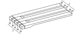
- FIG. 1 is a perspective view showing a schematic configuration of an embodiment of a planar lighting device according to the present invention.
- 2 is a perspective view of the planar illumination device shown in FIG. 1 as seen from the back side.
- the planar illumination device of the present embodiment includes a light guide plate 2 and a light source group 3 as shown in FIG.
- the light guide plate 2 is a light guide member that allows light from a light source to enter from an end surface that is a side edge thereof, propagates light, and emits light in a planar shape from a light exit surface formed on one surface of the light guide plate 2. is there.
- the planar illumination device of the present invention has a special structure in order to realize the above-described backlight blinking, so-called area control. Hereinafter, this point will be described.
- the light guide plate 2 has a light source group 3 disposed along one end face thereof, and a plurality of light guide portions extending along a direction away from the light source group 3 are provided along the one end face. It is formed in an array.
- a light guide plate 2 provided with five light guide portions 2A to 2E is shown.
- one light source corresponds to each light guide portion as shown in FIG. Specifically, the light source 3A is disposed on the one end surface side of the light guide portion 2A, the light source 3B is disposed on the one end surface side of the light guide portion 2B, and the light source is disposed on the one end surface side of the light guide portion 2C. 3C is disposed, the light source 3D is disposed on the one end surface side of the light guide portion 2D, and the light source 3E is disposed on the one end surface side of the light guide portion 2E.
- Each light source can control light emission and non-light emission independently of each other.
- Basics of area control by adopting a configuration in which light is emitted only from the light guide part supported by the light source that emits light (lights on) and light is not emitted from the light guide part that corresponds to the light source that does not emit light (lights off). Is realized.
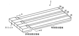
- FIG. 3 is a perspective view showing only the light guide plate 2 of FIG.
- the light guide plate 2 is provided with an effective light emitting region and an ineffective light emitting region.
- the light emitting surface of the light guide portion is in the effective light emitting region, and light is emitted from the light emitting surface. For this reason, in a liquid crystal display device described later, a display panel is disposed to face this effective light emitting region.
- the light emitting surface is not provided in the ineffective light emitting region, and the light source group 3 is disposed on the end surface provided in the ineffective light emitting region.
- a slit 23 is provided. The slit 23 penetrates from the surface of the light guide plate 2 shown in FIG. 1 to the back surface of the light guide plate 2 shown in FIG. 2, and also passes through the end face on which the light source group 3 is disposed. That is, the end face is divided into five areas by the slit 23. One area corresponds to one light guide portion.
- the ineffective light emitting regions can be optically separated from each other, so that the light from the light source arranged adjacent to each end face of the ineffective light emitting region divided by the slits Good area control can be realized without propagating to a light guide portion that does not correspond to the light source.
- the light source group 3 includes the five light sources 3A to 3E as described above, and is configured in such a manner that one light source is provided for one light guide member as described above.
- the light emission region of the light source is preferably within the range of the one area, and in particular, it is necessary to arrange a light source having a size that does not reach the adjacent area.
- the five light sources 3A to 3E can be composed of, for example, LEDs (Light Emitting Diodes).
- the light source group 3 may be provided with an LED board electrically connected to the light source.
- the configuration may be such that five light sources 3A to 3E are mounted on one LED substrate, or one or two or more light sources of five light sources 3A to 3E are mounted on one LED substrate. There may be.
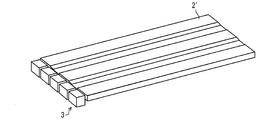
- the ineffective light-emitting region is not necessarily provided.
- the light guide plate 2 ' is an effective light-emitting region as a whole, and the light source group 3 is disposed on the end surface of the effective light-emitting region. It may be configured.
- the five light guide portions 2A to 2E of the light guide plate 2 have an integral structure rather than an independent structure. Therefore, the light guide plate 2 can be manufactured by integral molding using a mold.
- optically divided from each other means that light can be emitted only from a light guide portion corresponding to a light source that emits light, and light propagating through the light guide portion is a light source that does not emit light. It means that light does not exit from the light guide portion extending to the corresponding light guide portion.
- the light guide plate of the planar lighting device according to the present invention has a special structure for optical division in the effective light emitting region. This point will be described in detail below.
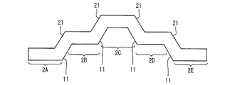
- FIG. 5 is a cross-sectional view of the light guide plate 2 taken along the cutting line AA ′ shown in FIG.
- the light guide plate 2 has five light guide portions 2A to 2E arranged generally in the left-right direction on the paper.
- Each of the five light guide portions 2A to 2E has a light emitting surface provided in the effective light emitting region and an opposite surface on the opposite side of each light emitting surface.
- the light guide portion 2A is formed with a light emitting surface 20a and an opposite surface 10a on the opposite side.
- the light guide portion 2B is formed with a light exit surface 20b and an opposite surface 10b on the opposite side.
- the light guide portion 2C is formed with a light exit surface 20c and an opposite surface 10c on the opposite side.
- the light guide portion 2D is formed with a light exit surface 20d and an opposite surface 10d on the opposite side.
- the light guide portion 2E is formed with a light exit surface 20e and an opposite surface 10e on the opposite side.
- the five light guide portions 2A to 2E are arranged with the light emitting surfaces 20a to 20e facing the same direction. That is, light is emitted from each of the light emitting surfaces 20a to 20e generally in the light emitting direction shown in FIG.
- the arrangement direction of the five light guide portions 2A to 2E is substantially perpendicular to the light emission direction, and each light emission surface 20a to 20e spreads in a two-dimensional direction perpendicular to the light emission direction. It can be said that it is a surface.
- the length between the light emitting surface and the opposite surface of each of the five light guide portions 2A to 2E, that is, the thickness of each light guide portion is configured to be equal to each other.
- the light guide plate 2 has two adjacent light guide portions that satisfy the following condition i, and the first connecting surface 21 that connects the adjacent light emitting surfaces 20a to 20e, and the adjacent opposite surface. And a second connecting surface 11 connecting 10a to 10e.
- the light guide portion 2B and the light guide portion 2C shown in FIG. 5 will be described as two adjacent light guide portions.
- condition i is; [Condition i]
- the opposite surface 10b of one light guide portion 2B (first light guide portion) of the adjacent light guide portions is more than the light exit surface 20c of the other light guide portion 2C (second light guide portion). It is a condition that it is at a high position along the light emission direction.
- condition i is that the light exit surface 20c of one light guide portion 2C (second light guide portion) of the adjacent light guide portions is connected to the other light guide portion 2B (first light guide portion). It is a condition that the opposite surface 10b of the portion) is at a higher position along the light emission direction.
- Portion) satisfies this condition i
- the light guide part 2A, the light guide part 2B, the light guide part 2C, the light guide part 2D, and the light guide part 2E are in this order, and the height along the light emitting direction is low, Steps are provided such as high, low, high and low.
- the “height along the light exit direction” represents a position along the direction from the opposite surface of a certain light guide portion toward the light exit surface.
- the height along the emission direction can be expressed as “higher” than the height along the light emission direction of the opposite surface.
- the light emission surface 20a of the light guide portion 2A, the light emission surface 20c of the light guide portion 2C, and the light emission surface 20e of the light guide portion 2E are the same height along the light emission direction.
- the light exit surface 20b of the light guide portion 2B and the light exit surface 20e of the light guide portion 2E are at the same height (high position).
- the light guide plate 2 of the present embodiment can be said to have a one-step surface change.
- the first connecting surface 21 and the second connecting surface 11 between the adjacent light guide portions that satisfy the condition i are smooth and inclined with respect to the light emitting surface and the opposite surface.
- An inclined surface may be used.
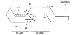
- FIG. 6 is an enlarged view of the light guide part 2C (second light guide part) and the light guide part 2D (first light guide part) shown in FIG.
- the light source 3C (FIGS. 1 and 2) corresponding to the light guide portion 2C is turned on, while the light source 3D (FIGS. 1 and 2) corresponding to the light guide portion 2D is turned off.
- the light introduced from the light source 3C to the light guide portion 2C propagates between the light emitting surface 20c and the opposite surface 10c in a direction away from the light source 3C.
- the propagating light is scattered by a reflection sheet, which will be described later, formed on the opposite surface 10c side of the light guide portion 2C, so that the total reflection condition is not satisfied, and finally from the light emitting surface 20c of the light guide portion 2C to the outside. It emits toward.
- the inconvenient light NGL propagating toward the light guide portion 2D must have a structure in which the light guide plate satisfies the above condition i. In this case, the light reaches the light guide portion 2D as it is and exits from the light exit surface 20d.
- inconvenient light NGL hits the first connecting surface 21 and the second connecting surface 11 which are inclined surfaces as shown in FIG. And repeat. In this way, the light is gradually attenuated by repeatedly reflecting and transmitting, and as a result, the inconvenient light NGL attenuates without reaching the light guide portion 2D.
- the light guide portion 2A (second light guide portion) and the light guide portion 2B (first light guide portion) satisfy the condition i and have the first connection surface 21 and the second connection surface 11. Between the light guide portion 2B (first light guide portion) and the light guide portion 2C (second light guide portion), and the light guide portion 2D (first light guide portion). Between the light guide portion) and the light guide portion 2E (second light guide portion).
- the inclination angle ⁇ of the first connecting surface 21 and the second connecting surface 11 is an angle of more than 0 degree and not more than 65 degrees (that is, at most 65 degrees) with respect to the light emitting direction. It has a slope.
- the tilt angle ⁇ exceeds the upper limit (65 degrees)
- the tilted portion becomes sufficiently large with respect to the pixel size, which increases the afterimage feeling.
- the angle formed by the light emitting surface that is a horizontal plane and the inclined surface becomes an obtuse angle. If the angle is 90 ° or an acute angle, the light concentrates at that angle and is easily recognized as a bright line. On the other hand, by satisfying the above angle condition and forming an obtuse angle, light is not concentrated on the corner of the structure having the angle. Thereby, it becomes difficult to be visually recognized as a bright line.
- the light guide plate 2 can be formed using a conventionally known light guide or a material used for the light guide plate.
- the light guide plate 2 is subjected to R processing at a boundary portion between each light emitting surface 20a to 20e and each first connection surface 21 and a boundary portion between each opposite surface 10a to 10e and the second connection surface 11. May be given. Thereby, an inflection point can be eliminated in the boundary portion, light concentration can be reduced, and visibility as a bright line can be reduced.
- the five light sources 3A to 3E can be arranged at equal heights along the arrangement direction of the light guide portions 2A to 2E. By arranging them at the same height in this way, it is possible to mount five light sources 3A to 3E on one LED substrate.
- FIG. 8 shows an arrangement pattern different from FIG. In the pattern shown in FIG. 8, each of the light sources 3A to 3E may be arranged with a height difference in accordance with the steps of the light guide portions 2A to 2E.
- one light source corresponds to one light guide portion.
- the present invention is not limited to this, and a plurality of light guide portions are provided. It is good also as a structure which the light source of this corresponds.
- the planar lighting device 1 includes a reflection sheet 4, a diffusion sheet 5, and a lens sheet 6, as shown in FIG.
- FIG. 9 is a cross-sectional view of the planar illumination device of this embodiment, and is a cross-sectional view of the planar illumination device cut along a direction away from the light source group 3.
- the reflection sheet 4 is disposed on the side opposite to the light emitting side of the light guide plate 2, that is, on the side of the opposite surfaces 10a to 10e of the light guide portions 2A to 2E.
- the light transmitted to the outside from the opposite surfaces 10 a to 10 e and the second connection surface 11 is incident on the reflection sheet 4 and reflected to enter the light guide plate 2. Let me introduce it again.
- the reflective sheet 4 is not overlapped only with the light guide plate 2 but is further spread out below the light source group 3 to directly guide light out of the light emitted from the light source group 3 directly.
- Light that is not incident on the end face of the optical plate 2 can be reflected and incident on the inside of the light guide plate 2 from the end face.
- a conventionally known reflection sheet 4 can be used.
- the diffusion sheet 5 is a light diffusing sheet disposed on the light emitting side of the light guide plate 2, that is, on the light emitting surface 20a to light emitting surface 20e side.
- a conventionally known sheet can be used, and diffuses when light emitted from at least one of the light emitting surface 20 a to the light emitting surface 20 e is incident, so that uniform light emission from the light emitting surface is performed. Can be realized.
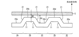
- FIG. 10 is a cross-sectional view corresponding to FIG. 5 in which the diffusion sheet 5 is disposed.
- the distance CH between the light emitting surface 20c at the low position and the diffusion sheet 5 is at the high position. It is longer than the distance BH between a certain light emitting surface 20 b and the diffusion sheet 5. If the distance between the light emitting surface and the diffusion sheet is long, the diffusibility of the emitted light is increased, so that the light emitted from the light emitting surface 20c can form a more uniform light emitting surface.
- the difference in the intensity of the emitted light due to the difference in height of the light emitting surface is different from the light emitting intensity from the light source, and the light source 3C corresponding to the light emitting surface 20c in the low position is made to emit light in the high position.
- the intensity from each light exit surface can be made equal.
- the lens sheet 6 is provided on the side of the diffusion sheet 5 opposite to the light guide plate 2 and is composed of one or a plurality of sheets.
- the lens sheet can give a desired refractive index to the light emitted from the diffusion sheet.
- FIG. 11 is a cross-sectional view showing another example of the step structure of the light guide plate.
- the light guide portion 2A, the light guide portion 2B, the light guide portion 2C, the light guide portion 2D, and the light guide portion 2E are in this order, and the height along the light emitting direction is low, high, and low. , High and low.
- the light guide portion 2A, the light guide portion 2B, the light guide portion 2C, the light guide portion 2D, and the light guide portion 2E are arranged in this order along the light emitting direction while satisfying the condition i.
- the height is three levels, low, medium, high, medium, and low, in other words, the structure is changed in two steps.
- the light emission direction height relationship between the light emission surface 20a of the light guide portion 2A and the light emission surface 20b of the light guide portion 2B is the light emission surface 20b (high)>.
- the light exit surface 20a (low) is formed.
- the height relationship between the light emitting surface 20b of the light guide portion 2B and the light emitting surface 20c of the light guide portion 2C in the light emitting direction is light emitting surface 20c (high)> light emitting surface 20b (low).
- the height relationship between the light exit surface 20c of the light guide portion 2C and the light exit surface 20d of the light guide portion 2D is such that the light exit surface 20c (high)> the light exit surface 20d (low).
- the height relationship between the light emitting surface 20d of the light guide portion 2D and the light emitting surface 20e of the light guide portion 2E in the light emitting direction is light emitting surface 20d (high)> light emitting surface 20e (low).
- the light exit surface 20a to the light exit surface 20e are sequentially arranged with respect to the height in the light exit direction.
- the light exit surface 20b and the light exit surface 20d have the same height, and the light exit surface 20a and the light exit surface 20e have the same height.
- Light output surface 20a), second layer (light output surface 20b), third layer (light output surface 20c), second layer (light output surface 20d), and first layer (light output surface 20e) It has become.
- the same effect as in FIG. 5 can be obtained by satisfying the condition i and having an inclined surface similar to FIG. 5 between the light guide portion and the light guide portion.
- ⁇ Another example of the light guide plate (2) / Another example of the first connecting surface and the second connecting surface> 12 is a cross-sectional view illustrating another example of the first connection surface and the second connection surface of the light guide plate, and is a partially enlarged cross-sectional view of the light guide plate corresponding to FIG. 6.
- the first connection surface 21 and the second connection surface 11 of the light guide plate 2 shown in FIG. 6 are planar inclined surfaces, whereas the first connection surface 21 ′ of the light guide plate 2 shown in FIG. And 2nd connection surface 11 'is a curved surface.
- the light emitting surfaces satisfying the above condition i and the opposite surfaces are connected by the first connecting surface 21 ′ and the second connecting surface 11 ′ which are curved surfaces.
- the light NGL hits the first connection surface 21 ′ and the second connection surface 11 ′ and repeats reflection and transmission. In this way, the light is gradually attenuated by repeatedly reflecting and transmitting, and as a result, the inconvenient light NGL attenuates without reaching the light guide portion 2D.
- the first connecting surface and the second connecting surface do not need to be flat inclined surfaces, and inconvenient light is reflected and transmitted so as not to block the light emitted from each light emitting surface.
- the shape is not particularly limited.
- FIG. 13 shows a liquid crystal display device 55 of the present embodiment.
- FIG. 13 is a diagram illustrating a schematic configuration of a liquid crystal display device that is an electronic apparatus including the planar illumination device 1 of the present embodiment.
- the liquid crystal display device 55 of the present embodiment includes a planar illumination device 1 that is a backlight, a liquid crystal panel 50, a backlight control unit 51, and a liquid crystal panel control unit 52. .
- liquid crystal panel 50 a conventionally known transmissive liquid crystal panel can be used.
- the light emitted from the light source group 3 of the planar illumination device 1 is irradiated to the liquid crystal panel 50 from the light emission surfaces 20 a to 20 e of the light guide plate 2 through the diffusion sheet 5 and the lens sheet 6.
- the backlight control unit 51 controls the light source group 3 to turn on and off the light sources 3A to 3E.
- a conventionally known backlight control unit 51 can be used.
- liquid crystal panel control unit 52 As the liquid crystal panel control unit 52 , a conventionally known one can be adopted, and the light transmittance of a liquid crystal layer (not shown) of the liquid crystal panel 50 is controlled.
- the backlight control unit 51 and the liquid crystal panel control unit 52 are configured to be synchronized.
- the planar illumination device 1 is divided and sequentially turned off in synchronism with the timing of applying the video signal to the liquid crystal panel, so that the interval between the image display and the image display is reduced.
- Backlight blinking which is a technology that inserts a black display into the screen, is realized. Thereby, pseudo-impulse type display can be realized, and afterimage feeling can be suppressed.
- the light emission from the light emission surface is opposite to the light emission surface of another light guide portion adjacent to the certain light guide portion. It is in a high position along the direction, and the adjacent light emitting surfaces are connected by the first connecting surface 21, and the adjacent opposite surfaces are connected by the second connecting surface 11. Accordingly, a difference in height is provided between the adjacent light guide portions, and the connection surface formed between the light guide portions is used to cause inconvenient light, that is, the light guide portion next to the light guide portion to be guided. Is transmitted and reflected repeatedly at the connecting surface. In this way, by repeating transmission and reflection on the connecting surface, the inconvenient light attenuates before reaching the adjacent light guide part, so that the inconvenient light does not enter the adjacent light guide part. Can do.
- the angle formed by the light emitting surface and the reflecting surface which are horizontal surfaces, and the inclined surface (an angle smaller than 180 degrees) an obtuse angle, it is possible to avoid the concentration of light at the angle and Can be prevented from being visually recognized as a bright line.
- the present invention is provided with a light guide plate.
- a light guide plate there is no need to fix them together.
- the individual light guide portions are arranged and fixed individually, it is necessary to align the positions of the end surfaces of the respective light guide portions, and if there is a misalignment, the distance between the light source and the end surfaces will be different.
- the light introduction rate varies depending on the light portion, and that the light introduction rate varies depending on the individual light guide portions.
- the light guide plate as in the present invention, it is not necessary to align the position of the end face of each light guide portion, and the distance between the light source and the end face is uniform, so the light introduction rate is also high. Can be even.
- Embodiment 2 The present embodiment described below has the same configuration as that of the first embodiment except that the condition i of the first embodiment described above is different. Therefore, for convenience of explanation, members having the same functions as those used in Embodiment 1 are given the same reference numerals, and explanations thereof are omitted.
- FIG. 14 is a partial enlarged cross-sectional view of a light guide plate disposed in the planar illumination device of the present embodiment, and corresponds to FIG.
- each light guide portion is equal to each other, and as a characteristic structure, two adjacent light guide portions satisfy the following condition ii.
- the first connection surface 21 that connects the adjacent light emitting surfaces 20a to 20e and the second connection surface 11 that connects the adjacent opposite surfaces 10a to 10e are provided.
- the light guide portion 2C and the light guide portion 2D among the five light guide portions will be described as two adjacent light guide portions.
- condition ii is; [Condition ii] An opposite surface 10d of one light guide portion 2D (first light guide portion) of adjacent light guide portions, and a light output surface 20c of the other light guide portion 2C (second light guide portion), The condition is that they are at the same position P along the light emission direction.
- the adjacent light guide part 2A (second light guide part) and the light guide part 2B (first light guide part) satisfy this condition ii
- the adjacent light guide part 2B (first light guide part 2B) 1 light guide portion) and the light guide portion 2C (second light guide portion) satisfy this condition ii
- the adjacent light guide portion 2C (second light guide portion) and light guide portion 2D (first light guide portion) The light guide portion) satisfies this condition ii
- the adjacent light guide portion 2D (first light guide portion) and light guide portion 2E (second light guide portion) satisfy this condition ii.
- the light guide portion 2A, the light guide portion 2B, the light guide portion 2C, the light guide portion 2D, and the light guide portion 2E are arranged in this order in the light emitting direction.
- the height along the line is low, high, low, high, low, and steps are provided.
- the light exit surface 20a of the light guide portion 2A, the light exit surface 20c of the light guide portion 2C, and the light exit surface 20e of the light guide portion 2E are at the same height (low position) along the light exit direction.
- the light exit surface 20b of the light guide portion 2B and the light exit surface 20e of the light guide portion 2E are at the same height (high position). That is, it can be said that the surface of the light guide plate 2 ′′ of the present embodiment is also changed by one step, as in FIG. 5 of the first embodiment.
- Embodiment 3 The present embodiment described below has the same configuration as that of the first embodiment except that the condition iii of the first embodiment described above is different. Therefore, for convenience of explanation, members having the same functions as those used in Embodiment 1 are given the same reference numerals, and explanations thereof are omitted.
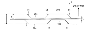
- FIG. 15 is a partially enlarged cross-sectional view of the light guide plate disposed in the planar illumination device of the present embodiment, and corresponds to FIG.
- each light guide portion is equal to each other, and as a characteristic structure, two adjacent light guide portions satisfy the following condition iii.
- a first connecting surface 21 that connects and connects adjacent light emitting surfaces 20a to 20e and a second connecting surface 11 that connects adjacent opposite surfaces 10a to 10e are provided.
- the light guide portion 2C and the light guide portion 2D among the five light guide portions will be described as two adjacent light guide portions.
- condition iii is; [Condition iii]
- the opposite surface 10d of one light guide portion 2D (first light guide portion) of adjacent light guide portions is lighter than the opposite surface 10c of the other light guide portion 2C (second light guide portion).
- the light exit surface 20d of the light guide portion 2D is at a higher position along the light exit direction than the light exit surface 20c of the light guide portion 2C; and
- the opposite surface 10d of the light guide portion 2D (first light guide portion) is positioned lower than the light emission surface 20c of the light guide portion 2C (second light guide portion) along the light emission direction.
- the adjacent light guide portion 2 A (second light guide portion) and the light guide portion 2 B (first light guide portion) satisfy this condition iii
- the adjacent light guide portions 2 B The first light guide portion) and the light guide portion 2C (second light guide portion) satisfy this condition iii
- the adjacent light guide portion 2C (second light guide portion) and light guide portion 2D first light guide portion.
- the light guide portion) satisfies this condition iii
- the adjacent light guide portion 2D (first light guide portion) and light guide portion 2E (second light guide portion) satisfy this condition iii.
- the light guide portion 2A, the light guide portion 2B, the light guide portion 2C, the light guide portion 2D, and the light guide portion 2E are arranged in this order in the light emitting direction.
- the height along the line is low, high, low, high, low, and steps are provided.
- the light exit surface 20a of the light guide portion 2A, the light exit surface 20c of the light guide portion 2C, and the light exit surface 20e of the light guide portion 2E are at the same height (low position) along the light exit direction.
- the light exit surface 20b of the light guide portion 2B and the light exit surface 20e of the light guide portion 2E are at the same height (high position). That is, it can be said that the surface of the light guide plate 2 ′′ of the present embodiment is also changed by one step, as in FIG. 5 of the first embodiment.
- the difference h is 35 of the thickness of the light guide portion (t in FIG. 15). % Or less, the difference h can be 0.1 mm or less. If the difference h exceeds 35% of the thickness of the light guide portion (t in FIG. 15), light leaks to the adjacent light guide portion, so the difference h is the thickness of the light guide portion (t in FIG. 15). ) 35% or less.
- each light guide portion can be 0.3 mm
- the maximum thickness of the light guide plate 2 can be 0.5 mm.
- Satisfying the above condition iii can also provide the same operational effects as those of the first embodiment, can be controlled to be turned on and off for each light guide portion, and can be a light emitting surface and a reflection surface that are horizontal surfaces. By making the angle formed by the surface and the inclined surface (an angle smaller than 180 degrees) an obtuse angle, the light is prevented from concentrating on the angle and the angle is prevented from being viewed as a bright line.
- a planar lighting device can be provided.
- the planar lighting device according to the present invention is as described above.
- a light guide plate in which a plurality of light guide portions each having a light emitting surface provided in an effective light emitting region and an opposite surface on the opposite side of the light emitting surface are arranged with each light emitting surface facing one side;
- a light source group arranged along the end face of the light guide plate so that one or more light sources correspond to each light guide portion, and a planar illumination device comprising:
- the light guide plate is (I) The opposite surface of the first light guide portion is more along the light emission direction from the light emission surface than the light emission surface of the second light guide portion adjacent to the first light guide portion.
- the opposite surface of the first light guide portion and the light exit surface of the second light guide portion adjacent to the first light guide portion are positioned at the same height along the light exit direction.
- the opposite surface of the first light guide portion is higher in the light emission direction from the light emission surface than the opposite surface of the second light guide portion adjacent to the first light guide portion.
- the light exit surface of the first light guide portion is higher than the light exit surface of the second light guide portion along the light exit direction from the light exit surface.
- the opposite surface of the first light guide portion is at a lower position along the light emission direction than the light emission surface of the second light guide portion, and the opposite surface of the first light guide portion and the light guide surface.
- the difference in height along the light exit direction with the light exit surface of the second light guide portion is at most 35% of the difference between the light exit surface of the light guide portion and the opposite surface
- the light guide plate has a first connection surface that connects the adjacent light emitting surfaces, and a second connection surface that connects the adjacent opposite surfaces.
- the corners of the light guide plate formed by the light emitting surface and the first connection surface and the corners of the light guide plate formed by the opposite surface and the second connection surface are obtuse. It is characterized by that.
- the planar illumination device has a light source corresponding to each light guide portion of the light guide plate, and the light emitted from the light source enters the inside of a certain light guide portion and away from the light source. Propagate to.
- a part of the propagating light is directed to another light guiding part adjacent to the certain light guiding part in the nature of light and in the process of propagation, and the conventional light guiding body (guided light).
- this light directly enters the adjacent light guide portion or is reflected on the side surface and is visually recognized as a bright line.
- the planar illumination device has the above-described configuration, thereby providing a difference in height between adjacent light guide portions and using a connection surface formed between the light guide portions.
- Inconvenient light that is, light directed to the light guide part adjacent to the light guide part to be guided is repeatedly transmitted and reflected on the connection surface. Thereby, it is possible to prevent the inconvenient light from entering the adjacent light guide portion.
- two adjacent light guide portions be a first light guide portion and a second light guide portion.
- the light guide surfaces of the first light guide portion and the second light guide portion are directed in the same direction, and the opposite surfaces corresponding to the opposite surfaces of the light output surface are also in the same direction (the light output surface is directed).
- Light from the light source corresponding to each light guide portion propagates through each light guide portion and exits from the light exit surface. That is, it can be said that the light emission surface is formed substantially perpendicular to the light emission direction, and the opposite surface on the opposite side of the light emission surface is also formed substantially perpendicular to the light emission direction. In other words, the light emission surface of a certain light guide portion is higher than the opposite surface with respect to the light emission direction.
- the light emission surface and the reflection surface of the adjacent first light guide portion and second light guide portion are the light emission surface. At different heights along the direction of light emission from and satisfies any of the above conditions (i) to (iii).
- the opposite surface of the first light guide portion is at a higher position along the light exit direction than the light exit surface of the second light guide portion, or in (ii) above
- the opposite surface of the first light guide portion and the light exit surface of the second light guide portion are positioned at the same height along the light exit direction.
- the first light guide portion and the second light guide portion are formed to have a step.
- connection surface disposed at a step portion corresponding to the boundary portion, and is repeatedly transmitted and reflected on the connection surface.
- the first connecting surface that connects the light emitting surface and the light emitting surface and the second connecting surface that connects the opposite surface and the opposite surface face each other. Because of this relationship, the light reflected from the first connecting surface (inconvenient light) is incident on the second connecting surface and is transmitted and reflected.
- the thickness from the light emitting surface to the reflecting surface in each light guide portion is equal, and the opposite surface of the first light guide portion is adjacent to the first light guide portion.
- the opposite surface of the first light guide portion and the second light guide even at a position lower than the light output surface of the matching second light guide portion along the light output direction from the light output surface.
- the planar illumination device includes a corner portion of the light guide plate formed by the light emitting surface and the first connection surface, and a light guide plate formed by the opposite surface and the second connection surface. Since the angle of the corner is an obtuse angle, light that concentrates on the angle is less than in the case where the angle of the corner is an acute angle. Therefore, no bright line is generated, and the display quality is not deteriorated by the bright line as before.
- the present invention is provided with a light guide plate.
- a light guide plate there is no need to fix them together.
- the individual light guide portions are arranged and fixed individually, it is necessary to align the positions of the end surfaces of the respective light guide portions, and if there is a misalignment, the distance between the light source and the end surfaces will be different.
- the light introduction rate varies depending on the light portion, and that the light introduction rate varies depending on the individual light guide portions.
- the light guide plate as in the present invention, it is not necessary to align the position of the end face of each light guide portion, and the distance between the light source and the end face is uniform, so the light introduction rate is also high. Can be even.
- one form of the planar illuminating device which concerns on this invention is It is preferable that the first connecting surface and the second connecting surface are inclined surfaces inclined with respect to the light emitting surface and the opposite surface.
- the inclined surface is preferably inclined with an angle of more than 0 degree and not more than 65 degrees with respect to the light emitting direction.
- one form of the planar illuminating device which concerns on this invention is It is preferable that a boundary portion between the light emitting surface and the first connecting surface is a curved surface.
- the boundary part of a light-projection surface and a 1st connection surface is a curved surface, and what is called R process is given, An inflection point is made in a boundary part (the said corner
- one form of the planar illuminating device which concerns on this invention is It is preferable that the first light guide portion and the second light guide portion are alternately arranged along the end face of the light guide.
- the first, second, first, second, first, second, and first light guide portions are alternately configured along the end surface of the light guide. That is, the step formed by the adjacent light guide portions changes by one step along the end face of the light guide, and has a step configuration of high, low, high, low, high, low, and high.
- the light guide plate can be realized in a relatively thin shape, which is particularly significant in an electronic device that requires a thin shape such as a mobile device. is there.
- one form of the planar illuminating device which concerns on this invention is It is preferable that the light guide portions are arranged along the end face of the light guide so that the light output surface is located at any one of three levels having different heights along the light output direction. .
- the light emitting surface is located at any one of the three layers having different heights along the light emitting direction, that is, the three layers are formed by the light emitting surfaces arranged along the end surface of the light guide. That means.
- the three layers are formed by the light emitting surfaces arranged along the end face of the light guide.
- three light guide portions A to C are arranged in this order along the end face of the light guide.
- the relationship among the heights of the light exit surface a, the light exit surface b, and the light exit surface c of the three light guide portions A, B, and C is as follows: light exit surface a (high)> light exit Surface b (medium)> light exit surface c (low).
- the light exit surface a of the light guide portion A and the light guide portion B has a height relationship in the light emission direction such that the light emission surface a (high)> the light emission surface b (low). Further, regarding the relationship between the light guide portion B and the light guide portion C, if the light guide portion B is the first light guide portion and the light guide portion C is the second light guide portion, the same as described above.
- the relationship between the heights of the light exit directions of the light exit surface b of the light guide portion B and the light exit surface c of the light guide portion C is such that the light exit surface b (high)> the light exit surface c (low). From these, the height relationship of the light exit surfaces of the three light guide portions of the light guide portion A, the light guide portion B, and the light guide portion C is as follows: light exit surface a (high)> light exit surface b (middle)> The light exit surface is c (low).
- the light guide portion A, the light guide portion B, the light guide portion C The height relationship between the light exit surface a, the light exit surface b, the light exit surface c, the light exit surface d, and the light exit surface e of the five light guide portions of the light guide portion D and the light guide portion E is, for example,
- the light guide plate is configured in three layers, with the light exit surface a and the light exit surface e being high, the light exit surface b and the light exit surface d being middle, and the light exit surface c being lower.
- the light guide portions A to C have the above-described relationship, and the light guide portion C and the light guide portion D are guided by using the light guide portion C as the second light guide portion.
- the portion D is the first light guide portion
- the height relationship in the light emission direction between the light exit surface c of the light guide portion C and the light exit surface d of the light guide portion D is the light exit surface d (high).
- Light exit surface c (low) and for the light guide portion D and the light guide portion E, the light guide portion D is the second light guide portion, and the light guide portion E is the first light guide portion.
- the light guide portion is a light emission surface d of the light guide portion D and the light emission surface e of the light guide portion E
- the height relationship in the light emission direction is: light emission surface e (high)> light emission surface d (low )
- the relationship between the heights of the light exit surfaces of the five light guide portions A to E is as follows: light exit surface a> light exit surface b> light exit surface c ⁇ light exit surface d ⁇ light exit surface e. Can be formed.
- a structure corresponding to a curved surface display can be realized by adopting a three-layer structure or a structure higher than the three layers in this way.
- one form of the planar illuminating device which concerns on this invention is
- the light guide plate has an ineffective light emitting region between the end face and the light exit surface, In the non-effective light emitting region, it is preferable that a slit is formed at a position corresponding to a boundary portion between the adjacent light emitting surfaces.
- the ineffective light emitting region can be optically separated by the slit.
- Favorable area control can be realized without propagating light from the light source adjacent to the end face to a light guide portion not supported by the light source.
- one form of the planar illuminating device which concerns on this invention is In the light source group, the light sources are preferably arranged at the same height along the end face.
- the light sources can be integrally configured, and positioning is easy.
- one form of the planar illuminating device which concerns on this invention is In the light source group, it is preferable that the light sources are arranged at different positions along the end surface in accordance with the position of the light emitting surface of each light guide portion.
- the light source can be disposed at the position closest to the corresponding light guide portion, the light use efficiency is high, and inconvenient light is not generated.
- one form of the planar illuminating device which concerns on this invention is It is preferable that a reflective sheet is provided on the opposite surface side of the light guide plate.
- emitted outside the light guide member can be reflected toward an opposite surface again by a reflective sheet, and again in the inside of a light guide member Can be introduced.
- the utilization efficiency of light can be improved.
- one form of the planar illuminating device which concerns on this invention is It is preferable that a diffusion sheet is provided on the light emitting surface side of the light guide plate.
- the diffusion sheet since the light emitted from the light emitting surface can be diffused by the diffusion sheet, uniform light can be emitted from the diffusion sheet.
- one form of the planar illuminating device which concerns on this invention is It is preferable that one or more lens sheets are provided on the opposite side of the diffusion sheet from the light guide plate.
- a desired refractive index can be imparted to the light emitted from the diffusion sheet by the plurality of lens sheets.
- the present invention includes an electronic device provided with a planar illumination device having the above-described configuration.
- the present invention also provides a liquid crystal display device comprising a planar illumination device having the above-described configuration and a liquid crystal display panel having a liquid crystal layer, wherein the liquid crystal display panel is used as the effective light emission of the light guide plate.
- a liquid crystal display device characterized in that the liquid crystal display device is disposed to face the region is also included.
- planar illumination device can be used not only as a general illumination device but also as a light source module such as a backlight, and can be applied to an electronic apparatus such as a liquid crystal display device.
Landscapes
- Physics & Mathematics (AREA)
- General Physics & Mathematics (AREA)
- Optics & Photonics (AREA)
- Planar Illumination Modules (AREA)
Abstract
本発明の一形態に係る面状照明装置(1)の導光板(2)は、隣り合う光出射面をつなぐ第1の連結面(21)と、隣り合う反対面をつなぐ第2の連結面(11)とを有しており、[条件i]導光部分(2B)の反対面(10b)が導光部分(2C)の光出射面(20c)よりも光出射方向に沿って高い位置にあるか、[条件ii]導光部分の反対面と隣り合う導光部分の光出射面とが光出射方向に沿って同じ位置にあるか、[条件iii]導光部分の反対面が隣り合う導光部分の光出射面よりも当該光出射方向に沿って低い位置にあるとともに当該反対面と当該光出射面との光出射方向に沿った高さの差が導光部分の光出射面と反対面との間の差の大きくとも35%である。
Description
本発明は、光源からの光を導光板によって面状に出射させる面状照明装置と、これを具備する例えば液晶表示装置といった電子機器に関するものである。
液晶表示装置の分野では、装置の薄型化を図るために、光源からの光を導光板によって面状に出射させるサイドエッジ(サイドライトともいう)型導光板を備えたバックライトが多用されている。またこれに加えて、導光板を複数の領域に分割して各分割領域に光源を対応させ、所望の光源を発光させることでこれに対応する分割領域(発光領域)のみから光を出射するというエリア制御を行うことが知られている。このようなエリア制御によって、疑似インパルス型の表示を実現したり、液晶表示素子の液晶層において光透過率を制御しつつ、バックライトにおいても特定のエリアの輝度調整を行うことで、表示品位の向上を図ったりすることができる。
例えば特許文献1には、導光板のエリア制御を実現した照明装置が開示されている。図16は、特許文献1の照明装置の平面図である。また、図17は、図16に示す線分A-A´における矢視断面図である。図16および図17の照明装置101においては、一列に配列された複数のブロック102aからなる導光板102と、ブロック102aごとに設けられ、ブロック102aに対して光を照射する複数の光源103とが設けられている。そして、隣り合うブロック102a間の少なくとも一部の領域には、0.1ミクロン以上の隙間が形成されており隙間内は空気層105となってことにより、ブロック同士を光学的に分離している。また、導光板102の上面および下面のうち少なくとも一方には、光を拡散させるためのプリズムまたはパターン(図示せず)が形成されている。
図16および図17の照明装置101において1つの光源103が光を出射すると、この光が導光板102の端面から1つのブロック102aの内部に進入し、ブロック102aの表面(すなわち、導光板102の側面を形成する面102bまたはブロック102aと空気層105との界面、並びにブロック102aの上面および下面)において全反射され、ブロック102a内を光源103から遠ざかる方向に伝播していく。図16においては、この光の伝播経路を光路Lとして例示している。この伝播の過程で、光はブロック102aの上面および/または下面に形成されたプリズムまたはパターンにより散乱され、全反射条件を満たさなくなった光は、ブロック102aの上面または下面から外部に向けて出射する。なお、ブロック102aにおいて、光の進行方向下流側ほど、プリズムまたはパターンの形成密度を高くすることにより、導光板102から均一に光を出射させる。これにより、導光板102から面状に光を出射させる。これにより、あるブロックを発光させているときに、このブロックに隣接する他のブロックが発光することがなく、疑似インパルス型の表示を実現することができる。
また、特許文献1には、図18に示す導光板も開示されている。図18は図17に対応した構成である。図18は、導光板282cに楔形の溝284cが形成されており、この溝284cにより、導光板282cが複数のブロック282dに分割されている。従って、ブロック282dの長手方向に直交する断面の形状は、台形となっている。ブロック282dのテーパ角、すなわち、導光板282cの表面に垂直な方向に対する溝284cの側面がなす角度は、例えば5度である。また、溝284cは、その長手方向において導光板282cを貫通しているが、導光板282cの厚さ方向においては導光板282cを貫通していない。これにより、隣り合うブロック282d同士は、局所的に光学的に結合されている。
しかしながら、図16および図17の構成では、ブロック102aにおける端辺(ブロック102aの側面のエッジ)において輝線が生じ、これが表示品位を劣化させる原因となってしまう。
具体的には、図16および図17の構成において、隣り合う2つのブロック102aのうち、一方のブロック102aに対応する光源が点灯して、他方のブロック102aに対応する光源が消灯している場合を想定する。光源が点灯しているブロック102aを伝播する光は、その一部が当該ブロック102aと空気層105との界面において反射と透過とを繰り返す。反射した光は再び当該ブロック102a内を伝播する。一方、当該界面を透過した光は、当該ブロック102aと隣り合うブロック102aと当該空気層105との界面において、反射して再び当該ブロック102aに入射する。しかしながら、図17のようにブロック102aにおける端辺が鋭角で構成されている場合、そこに光が集中し輝線として視認されやすい。このような導光板を表示装置のバックライトとして採用した場合、表示装置の表示品位を著しく劣化させてしまうことになる。
ここで、携帯電話のようなモバイル機器は厚さに制限があるため導光板の光出射側に設置できる光拡散手段はシート状の薄層とする必要がある。そのため、モバイル機器では、大型の表示装置と比べて光拡散手段において十分な光拡散性を望めない。したがって、図16および図17の導光板に生じる輝線は、モバイル機器においては重大な問題となる。
また、図18の構成の場合も、隣り合うブロック282dの間に形成されているスリット(空気層105)のなす角度が鋭角であり、この形状では輝線が発生する。
本発明は、上記従来の問題点に鑑みなされたものであって、その目的は、輝線を生じさせることなく、且つ、エリア制御を実現することができる導光板を有した面状照明装置、および、それを備えた電子機器、並びに液晶表示装置を提供することにある。
すなわち、本発明に係る面状照明装置は、上記の課題を解決するために、
有効発光領域内に設けられた光出射面と、当該光出射面の反対側にある反対面とを有する複数の導光部分が各光出射面を一方側に向けて配列している導光板と、当該導光部分ごとに1つまたは複数の光源が対応するように当該導光板の端面に沿って配列した光源群と、を備えた面状照明装置であって、
上記導光板は、
(i) 第1の上記導光部分の反対面が、当該第1の導光部分と隣り合う第2の導光部分の光出射面よりも、当該光出射面からの光出射方向に沿って高い位置にあるか、
(ii) 上記第1の導光部分の反対面と、当該第1の導光部分と隣り合う第2の導光部分の光出射面とが上記光出射方向に沿って同じ高さに位置しているか、もしくは、
(iii) 第1の上記導光部分の反対面は、当該第1の導光部分と隣り合う第2の上記導光部分の反対面よりも当該光出射面からの光出射方向に沿って高い位置にあり、且つ、当該第1の上記導光部分の光出射面は、当該第2の上記導光部分の光出射面よりも当該光出射面からの光出射方向に沿って高い位置にあり、且つ、第1の導光部分の反対面は、第2の導光部分の光出射面よりも当該光出射方向に沿って低い位置にあるとともに当該第1の導光部分の反対面と当該第2の導光部分の光出射面との光出射方向に沿った高さの差が、導光部分の光出射面と反対面との間の差の大きくとも35%であり、
上記導光板は、隣り合う上記光出射面をつなぐ第1の連結面と、隣り合う上記反対面をつなぐ第2の連結面とを有しており、
上記光出射面と上記第1の連結面とによって形成される導光板の角部、および、上記反対面と上記第2の連結面とによって形成される導光板の角部は、角度が鈍角である、ことを特徴としている。
有効発光領域内に設けられた光出射面と、当該光出射面の反対側にある反対面とを有する複数の導光部分が各光出射面を一方側に向けて配列している導光板と、当該導光部分ごとに1つまたは複数の光源が対応するように当該導光板の端面に沿って配列した光源群と、を備えた面状照明装置であって、
上記導光板は、
(i) 第1の上記導光部分の反対面が、当該第1の導光部分と隣り合う第2の導光部分の光出射面よりも、当該光出射面からの光出射方向に沿って高い位置にあるか、
(ii) 上記第1の導光部分の反対面と、当該第1の導光部分と隣り合う第2の導光部分の光出射面とが上記光出射方向に沿って同じ高さに位置しているか、もしくは、
(iii) 第1の上記導光部分の反対面は、当該第1の導光部分と隣り合う第2の上記導光部分の反対面よりも当該光出射面からの光出射方向に沿って高い位置にあり、且つ、当該第1の上記導光部分の光出射面は、当該第2の上記導光部分の光出射面よりも当該光出射面からの光出射方向に沿って高い位置にあり、且つ、第1の導光部分の反対面は、第2の導光部分の光出射面よりも当該光出射方向に沿って低い位置にあるとともに当該第1の導光部分の反対面と当該第2の導光部分の光出射面との光出射方向に沿った高さの差が、導光部分の光出射面と反対面との間の差の大きくとも35%であり、
上記導光板は、隣り合う上記光出射面をつなぐ第1の連結面と、隣り合う上記反対面をつなぐ第2の連結面とを有しており、
上記光出射面と上記第1の連結面とによって形成される導光板の角部、および、上記反対面と上記第2の連結面とによって形成される導光板の角部は、角度が鈍角である、ことを特徴としている。
上記の構成によれば、輝線を生じさせることなく、且つ、エリア制御を実現することができる導光板を有した面状照明装置を提供することができる。
本発明に係る面状照明装置は、導光板の各導光部分に対応する光源を有し、光源から出射した光が或る導光部分の内部に進入して、当該内部を光源から遠ざかる方向に伝播する。従来から知られているように、伝播する光の一部は、光の性質上および伝播の過程で当該或る導光部分と隣り合う別の導光部分に向かい、従前の導光体(導光板)ではこの光がそのまま隣接する導光部分に侵入してしまったり、側面において反射して輝線として視認されてしまったりという問題がある。これに対して本発明に係る面状照明装置は、上記構成を具備することによって、隣り合う導光部分に高さの差を設けて、導光部分同士の間に形成した連結面を用いて、不都合な光、すなわち導光させたい導光部分の隣の導光部分に向かう光、を当該連結面において繰り返し透過、反射させる。これにより、当該不都合な光を上記隣の導光部分に侵入させないようにすることができる。
より具体的には、隣り合う2つの導光部分を第1の導光部分と第2の導光部分とする。第1の導光部分および第2の導光部分は、光出射面が同一方向を向いており、当該光出射面の反対側の面に相当する反対面同士も同一方向(光出射面が向いた方向とは反対側の方向)を向いている。各導光部分に対応した光源からの光は、各導光部分内部を伝播して、光出射面から出射する。すなわち、光出射方向に対して、光出射面はほぼ垂直に形成されており、光出射面の反対側にある反対面も光出射方向にほぼ垂直に形成されているといえる。換言すれば、光出射方向に対して、或る導光部分の光出射面はその反対面よりも高い位置にある。
このような第1の導光部分と第2の導光部分に関して、本発明では、隣り合う第1の導光部分と第2の導光部分の光出射面、反射面が、当該光出射面からの光出射方向に沿って異なる高さにあり、上記(i)~(iii)の条件のうちのいずれかを満たしている。
まず、上記(i)のように、第1の導光部分の反対面が第2の導光部分の光出射面よりも光出射方向に沿って高い位置にある、もしくは、上記(ii)のように第1の導光部分の反対面と第2の導光部分の光出射面とが光出射方向に沿って同じ高さに位置している。
すなわち、第1の導光部分と第2の導光部分とは段差を有するように形成されている。
このような構成とすると、例えば第1の導光部分の内部を伝播する光が、第2の導光部分に直接入射することなく、第1の導光部分と第2の導光部分との境界部分に相当する段差部分に配設された連結面に入射して当該連結面において繰り返し透過、反射する。
ここで、上記(i)または(ii)の条件下において、光出射面と光出射面とをつなぐ第1の連結面と、反対面と反対面とをつなぐ第2の連結面とは対向する関係になるので、第1の連結面において反射した光(不都合な光)は、第2の連結面に入射して透過、反射する。
このように、対向する2つの連結面の間で透過、反射を繰り返すことによって、不都合な光は隣の導光部分に到達するまでに減衰して、隣の導光部分には侵入しない構成を実現することができる。
よって、上記(i)または(ii)の条件下においては、高いエリア制御を実現することができる。
次に、上記(iii)のように、各導光部分における光出射面から反射面までの厚さが等しく、第1の上記導光部分の反対面が、当該第1の導光部分と隣り合う第2の導光部分の光出射面よりも、当該光出射面からの光出射方向に沿って低い位置にあっても、当該第1の導光部分の反対面と当該第2の導光部分の光出射面との光出射方向に沿った高さの差が、導光部分の光出射面と反対面との間の差に対して、大きくとも35%であるという条件を満たすことによって、対向する2つの連結面の間によって不都合な光を透過、反射させて、隣の導光部分において不都合に光出射しないレベルまで減衰させることができる。
また、本発明に係る面状照明装置は、光出射面と第1の連結面とによって形成される導光板の角部、および、反対面と第2の連結面とによって形成される導光板の角部は、角度が鈍角であることから、当該角部の角度が鋭角である場合に比べて、当該角度に集中する光がすくなくなる。よって、輝線が生じず、従前のような輝線による表示品位の劣化を生じさせない。
よって、以上の構成を採用することによって、輝線を生じさせることなく、且つ、エリア制御を実現することができる導光板を有した面状照明装置を提供することができる。
また例えば、複数の分割ブロックを固定冶具などによって固定して1つの導光体を形成しているものと比較して、本発明に具備されるのは導光板であることから、導光部分それぞれを互いに固定する必要がない。また仮に個々に独立した導光部分を並べて固定する構成の場合、各導光部分の端面の位置を揃える必要があり、位置ズレが生じれば、光源と端面との間の距離が個々の導光部分によってばらついて光の導入率が個々の導光部分によって異なる虞がある。しかしながら、本発明のように導光板を具備することによって、各導光部分の端面の位置を揃える作業が不要であり、また光源と端面との間の距離が均等であるので光の導入率も均等にすることができる。
また、本発明には、上記した構成を具備する面状照明装置を備えた電子機器も含まれる。
また、本発明は、上述した構成を有した面状照明装置と、液晶層を有した液晶表示パネルとを備えた液晶表示装置であって、上記液晶表示パネルを、上記導光板の上記有効発光領域に対向配置していることを特徴とする液晶表示装置も含まれる。
本発明は、以上のように、有効発光領域内に設けられた光出射面と、当該光出射面の反対側にある反対面とを有する複数の導光部分が各光出射面を一方側に向けて配列している導光板と、当該導光部分ごとに1つまたは複数の光源が対応するように当該導光板の端面に沿って配列した光源群と、を備えた面状照明装置であって、
上記導光板は、
(i) 第1の上記導光部分の反対面が、当該第1の導光部分と隣り合う第2の導光部分の光出射面よりも、当該光出射面からの光出射方向に沿って高い位置にあるか、
(ii) 上記第1の導光部分の反対面と、当該第1の導光部分と隣り合う第2の導光部分の光出射面とが上記光出射方向に沿って同じ高さに位置しているか、もしくは、
(iii) 第1の上記導光部分の反対面は、当該第1の導光部分と隣り合う第2の上記導光部分の反対面よりも当該光出射面からの光出射方向に沿って高い位置にあり、且つ、当該第1の上記導光部分の光出射面は、当該第2の上記導光部分の光出射面よりも当該光出射面からの光出射方向に沿って高い位置にあり、且つ、第1の導光部分の反対面は、第2の導光部分の光出射面よりも当該光出射方向に沿って低い位置にあるとともに当該第1の導光部分の反対面と当該第2の導光部分の光出射面との光出射方向に沿った高さの差が、導光部分の光出射面と反対面との間の差の大きくとも35%であり、
上記導光板は、隣り合う上記光出射面をつなぐ第1の連結面と、隣り合う上記反対面をつなぐ第2の連結面とを有しており、
上記光出射面と上記第1の連結面とによって形成される導光板の角部、および、上記反対面と上記第2の連結面とによって形成される導光板の角部は、角度が鈍角であることを特徴としている。
上記導光板は、
(i) 第1の上記導光部分の反対面が、当該第1の導光部分と隣り合う第2の導光部分の光出射面よりも、当該光出射面からの光出射方向に沿って高い位置にあるか、
(ii) 上記第1の導光部分の反対面と、当該第1の導光部分と隣り合う第2の導光部分の光出射面とが上記光出射方向に沿って同じ高さに位置しているか、もしくは、
(iii) 第1の上記導光部分の反対面は、当該第1の導光部分と隣り合う第2の上記導光部分の反対面よりも当該光出射面からの光出射方向に沿って高い位置にあり、且つ、当該第1の上記導光部分の光出射面は、当該第2の上記導光部分の光出射面よりも当該光出射面からの光出射方向に沿って高い位置にあり、且つ、第1の導光部分の反対面は、第2の導光部分の光出射面よりも当該光出射方向に沿って低い位置にあるとともに当該第1の導光部分の反対面と当該第2の導光部分の光出射面との光出射方向に沿った高さの差が、導光部分の光出射面と反対面との間の差の大きくとも35%であり、
上記導光板は、隣り合う上記光出射面をつなぐ第1の連結面と、隣り合う上記反対面をつなぐ第2の連結面とを有しており、
上記光出射面と上記第1の連結面とによって形成される導光板の角部、および、上記反対面と上記第2の連結面とによって形成される導光板の角部は、角度が鈍角であることを特徴としている。
これにより、輝線を生じさせることなく、且つ、エリア制御を実現することができる導光板を有した面状照明装置、および、それを備えた電子機器、並びに液晶表示装置を提供することができる。
以下に、本発明の一実施形態を説明する。なお、本実施形態の後半において、本発明の面状照明装置を具備する電子機器として、面状照明装置をバックライトとして搭載した液晶表示装置について説明する。一般に液晶表示装置は、CRT(Cathode-Ray Tube:陰極線管)表示装置と比較して、動画のボヤケという問題点がある。すなわち、CRT表示装置においては、あるフレームにおける画素の発光期間と、次のフレームにおけるこの画素の発光期間との間に、この画素が発光しない非発光期間があるため、残像感が少ない。これに対して、液晶表示装置の表示方式はこのような非発光期間がない「ホールド型」であるため、残像感が生じ、この残像感が使用者に動画のボヤケとして認識される。そこで、本実施形態におけるバックライト型の液晶表示装置においては、後述するようにバックライトである面状照明装置1を分割し、液晶パネルに映像信号を印加するタイミングに同期して順次消灯することにより、画像表示と画像表示との間に黒表示を挿入する技術であるバックライトブリンキングを実現することができる構成である。これにより、疑似インパルス型の表示を実現し、残像感を抑えることができる。以下では、まず本実施形態の面状照明装置について、説明する。
<面状照明装置>
図1は、本発明に係る面状照明装置の一実施形態の概略構成を示す斜視図である。また図2は、図1に示す面状照明装置を裏側からみた斜視図である。
図1は、本発明に係る面状照明装置の一実施形態の概略構成を示す斜視図である。また図2は、図1に示す面状照明装置を裏側からみた斜視図である。
本実施形態の面状照明装置は、図1に示すように、導光板2と、光源群3とを備えている。
上記導光板2は、そのサイドエッジである端面から光源の光を入射させて、光を伝播させ、導光板2の一表面に形成した光出射面から面状に光を出射させる導光部材である。このような導光部材としては一般的に知られているが、本発明の面状照明装置は、上述したバックライトブリンキング、いわゆるエリア制御を実現するべく、特殊な構造を有している。以下、この点を説明する。
導光板2は、図1に示すように、その一端面に沿って光源群3を配設しており、光源群3から離れる方向に沿って延びる導光部分が、当該一端面に沿って複数配列したかたちに形成されている。本実施形態では、図1に示すように5つの導光部分2A~2Eを設けた導光板2を示している。
そして、導光板2は、図1に示すように、各導光部分に1つの光源が対応している。具体的には、導光部分2Aにおける上記一端面側に光源3Aを配設し、導光部分2Bにおける上記一端面側に光源3Bを配設し、導光部分2Cにおける上記一端面側に光源3Cを配設し、導光部分2Dにおける上記一端面側に光源3Dを配設し、導光部分2Eにおける上記一端面側に光源3Eを配設している。
各光源は、互いに独立して発光、非発光を制御することができる。発光する光源が対応している導光部分のみから光を出射させ(点灯)、発光しない光源に対応している導光部分からは光を出射させない(消灯)構成とすることでエリア制御の基本を実現している。
図3は、図1の導光板2のみを示した斜視図である。導光板2には、有効発光領域と非有効発光領域とが設けられており、導光部分の光出射面は有効発光領域内にあって当該光出射面から光が出射される。そのため、後述する液晶表示装置においては、この有効発光領域に表示パネルを対向配置させている。
一方、非有効発光領域は、上記光出射面は設けられておらず、光源群3は、この非有効発光領域に設けられた端面に配設されている。
導光板2の非有効発光領域には、隣り合う導光部分同士の境界部分に対応した位置に、非有効発光領域の有効発光領域側の端部から、光源群3が配設された端面に至る、スリット23が設けられている。スリット23は、図1に示す導光板2の表面から、図2に示す導光板2の裏面まで貫通していて、光源群3が配設された端面にも通っている。すなわち、スリット23によって、上記端面が5つのエリアに分かれている。1つのエリアは、1つの導光部分に対応している。
このように、スリットを設けることによって、非有効発光領域は個々を光学的に分離することができるので、スリットによって分割された非有効発光領域の各端面に隣接配置した光源からの光を、当該光源が対応していない導光部分に伝播させることがなく、良好なエリア制御を実現することができる。
光源群3は、上述のように5つの光源3A~3Eを有しており、上述のように1つの導光部材に対して1つの光源が配設されるかたちに構成されている。光源の光出射領域は、上記1つのエリアの範囲内にあることが好ましく、特に、隣接するエリアに出射した光が及ばない大きさの光源を配設する必要がある。5つの光源3A~3Eとしては、例えばLED(Light Emitting Diode:発光ダイオード)から構成することができる。
また光源群3には、光源3A~3Eに加えて、光源に電気的に接続したLED基板を設けても良い。このとき5つの光源3A~3Eが1つのLED基板に実装された構成であってもよいし、5つの光源3A~3Eの1つまたは2つ以上の光源を1つのLED基板に実装した構成であってもよい。
なお、非有効発光領域は、必ずしも設けなくてもよく、例えば図4のように導光板2´が全体的に有効発光領域となっていて、その有効発光領域の端面に光源群3が配設されている構成であってもよい。
ところで、導光板2の5つの導光部分2A~2Eは、互いに独立した構造ではなく、一体的な構造となっている。そのため、導光板2は、金型を用いた一体成形によって製造することができる。
そして本発明の特徴は、このように5つの導光部分が構造的に一体的であるにもかかわらず、光学的には導光部分同士が分割されている点にある。ここで、光学的には互いに分割しているとは、発光した光源に対応している導光部分のみから光を出射することができ、当該導光部分を伝播する光が、発光しない光源に対応している導光部分に及んでこの導光部分からも光が出射してしまうことがないことをいう。
すなわち、本発明に係る面状照明装置の導光板は、光学的に分割するための特殊な構造を有効発光領域に有している。以下に、この点を詳述する。
図5は、図3に示す切断線A-A´において導光板2を切断した状態を示した矢視断面図である。
導光板2は、図5に示すように、概して紙面左右方向に5つの導光部分2A~2Eが配列している。そして、5つの導光部分2A~2Eはそれぞれ、有効発光領域内に設けられた光出射面と、各光出射面の反対側にある反対面とを有している。
具体的には、導光部分2Aには、光出射面20aと、その反対側にある反対面10aとが形成されている。また、導光部分2Bには、光出射面20bと、その反対側にある反対面10bとが形成されている。また、導光部分2Cには、光出射面20cと、その反対側にある反対面10cとが形成されている。また、導光部分2Dには、光出射面20dと、その反対側にある反対面10dとが形成されている。また、導光部分2Eには、光出射面20eと、その反対側にある反対面10eとが形成されている。
5つの導光部分2A~2Eは、各光出射面20a~20eを同一方向に向けて、配列している。すなわち、各光出射面20a~20eからは、概して図5に示す光出射方向に光が出射する。
よって換言すれば、5つの導光部分2A~2Eの配列方向は光出射方向に対してほぼ垂直であり、各光出射面20a~20eは光出射方向に対して垂直な二次元方向に広がった面であるといえる。
5つの導光部分2A~2Eそれぞれの光出射面と反対面との間の長さ、すなわち各導光部分の厚さは互いに等しく構成されている。
そして、特徴的構造として、導光板2は隣り合う2つの導光部分が次の条件iを満たし、且つ、隣り合う光出射面20a~20eをつなぐ第1の連結面21と、隣り合う反対面10a~10eをつなぐ第2の連結面11とを有している。なお、以下では隣り合う2つの導光部分として図5に示す導光部分2Bと導光部分2Cとを例に挙げて説明する。
すなわち、条件iとは;
[条件i]
隣り合う導光部分のうちの一方の導光部分2B(第1の導光部分)の反対面10bが、他方の導光部分2C(第2の導光部分)の光出射面20cよりも、光出射方向に沿って高い位置にある
という条件である。
[条件i]
隣り合う導光部分のうちの一方の導光部分2B(第1の導光部分)の反対面10bが、他方の導光部分2C(第2の導光部分)の光出射面20cよりも、光出射方向に沿って高い位置にある
という条件である。
この条件iは、換言すれば、隣り合う導光部分のうちの一方の導光部分2C(第2の導光部分)の光出射面20cが、他方の導光部分2B(第1の導光部分)の反対面10bよりもが光出射方向に沿って高い位置にあるという条件である。
導光板2は、隣り合う導光部分2A(第2の導光部分)と導光部分2B(第1の導光部分)とがこの条件iを満たし、隣り合う導光部分2B(第1の導光部分)と導光部分2C(第2の導光部分)とがこの条件iを満たし、隣り合う導光部分2C(第2の導光部分)と導光部分2D(第1の導光部分)とがこの条件iを満たし、隣り合う導光部分2D(第1の導光部分)と導光部分2E(第2の導光部分)とがこの条件iを満たしている。
すなわち、図5に示すように、導光部分2A、導光部分2B、導光部分2C、導光部分2D、導光部分2Eがこの順で、光出射方向に沿った高さが、低、高、低、高、低となって段差が設けられている。
ここで「光出射方向に沿った高さ」とは、或る導光部分の反対面から光出射面に向かう方向に沿った位置を表しており、この表現においては、当該光出射面の光出射方向に沿った高さは、当該反対面の光出射方向に沿った高さよりも「高い」と表現することができる。
本実施形態の場合は、導光部分2Aの光出射面20aと、導光部分2Cの光出射面20cと、導光部分2Eの光出射面20eとが互いに光出射方向に沿って同じ高さ(低位置)にあり、導光部分2Bの光出射面20bと、導光部分2Eの光出射面20eとが互いに同じ高さ(高位置)にある。すなわち、本実施形態の導光板2は、表面が一段変化していると換言することもできる。
この条件iを満たす隣り合う導光部分の間にある上記第1の連結面21および上記第2の連結面11は、図5のように、光出射面および反対面に対して傾斜した平滑な傾斜面とすればよい。
以下、この条件iによって奏する効果について図6に基づいて説明する。図6は、図5に示す導光部分2C(第2の導光部分)および導光部分2D(第1の導光部分)を拡大した図である。
図6では、導光部分2Cに対応する光源3C(図1および図2)が点灯している一方、導光部分2Dに対応する光源3D(図1および図2)は消灯している状態を示している。光源3Cから導光部分2Cに導入された光は、光源3Cから離れる方向に光出射面20cと反対面10cとの間を伝播する。伝播する光は、導光部分2Cの反対面10c側に形成されている後述する反射シートにより散乱されて、全反射条件を満たさなくなり、最終的に導光部分2Cの光出射面20cから外部に向けて出射する。この伝播の過程で、光の一部が、光の性質上および伝播の過程で隣の導光部分2Dに向かって伝播する。ここで、導光部分2Dと導光部分2Cとは構造的に一体であるため、この導光部分2Dに向かって伝播する不都合な光NGLは、もし導光板が上記条件iを満たす構造でなければ、そのまま導光部分2Dに到達して光出射面20dから出射してしまう。しかしながら、本実施形態では、導光板が上記条件iを満たしているため、不都合な光NGLは図6に示すように傾斜面である第1の連結面21および第2の連結面11に当たって、反射と透過とを繰り返す。このように繰り返し反射、透過することで徐々に減衰し、結果的に、不都合な光NGLは導光部分2Dに到達することなく減衰する。
ここで説明した作用効果は、条件iを満たし且つ第1の連結面21および第2の連結面11を有する、導光部分2A(第2の導光部分)と導光部分2B(第1の導光部分)との間でも成立し、導光部分2B(第1の導光部分)と導光部分2C(第2の導光部分)との間でも成立し、導光部分2D(第1の導光部分)と導光部分2E(第2の導光部分)との間でも成立する。
よって、導光部分ごとに点灯と消灯とを精度良く制御することができる。
また、複数の連結面において透過、反射を繰り返すので、一つの面のみが反射によって輝くことはなく、従前のような輝線を生じさせない。
また、上記第1の連結面21および上記第2の連結面11の傾斜角度θは、光出射方向に対して、0度を超えて、65度以下(すなわち大きくても65度)、の角度を有して傾斜している。
傾斜角度θが上限値(65度)を超えると、傾斜部が画素サイズに対し充分に大きくなり残像感が増すため好ましくない。
換言すれば、上記の角度条件を満たすことによって、水平面である光出射面と、傾斜面とがなす角度(180度よりも小さいほうの角度)が鈍角になる。もし当該角度が90°もしくは鋭角であるとその角に光が集中して輝線として視認されやすい。これに対して、上記の角度条件を満たして鈍角に構成することによって角を有する構成のその角に光が集中させない。これにより、輝線として視認されにくくなる。
導光板2は、従来周知の導光体や導光板に用いる材料を用いて形成することができる。
また、導光板2は、各光出射面20a~20eと各第1の連結面21との境界部分、および、各反対面10a~10eと第2の連結面11との境界部分に、R加工が施されていてもよい。これにより、境界部において変曲点をなくし、光の集中を低減し、輝線として視認されることを低減することができる。
ここで、図5において、光源3A~3Eを配設した例を図7に示す。図7に示すように、5つの光源3A~3Eは、導光部分2A~2Eの配列方向に沿って、互いに等しい高さで配列することができる。このように互いに同じ高さに配列することによって、1つのLED基板に5つの光源3A~3Eを実装することができる。
また、図7とは異なる配設パターンを図8に示す。図8に示すパターンでは、光源3A~3Eのそれぞれが、導光部分2A~2Eの段差に合わせて、高低差を有して配設されていてもよい。
なお、以上の説明では、1つの導光部分に対して1つの光源が対応している構成であるが、本発明はこれに限定されるものではなく、1つの導光部分に対して複数個の光源が対応する構成としてもよい。
以上が、本実施形態の面状照明装置の特徴的構成についての説明である。
ところで、面状照明装置1は、この構成以外の構成として、図9に示すように反射シート4と、拡散シート5と、レンズシート6とを備えている。なお、図9は、本実施形態の面状照明装置の断面図であり、光源群3から離れる方向に沿って面状照明装置を切断した状態の断面図である。
反射シート4は、導光板2の光出射側とは反対側、すなわち、各導光部分2A~2Eの反対面10a~10e側に配設されている。光源群3から導光板2に導入された光のうち、反対面10a~10eおよび第2の連結面11から外部に透過した光が反射シート4に入射し、反射することによって、導光板2に再び導入させる。
また、反射シート4を、導光板2とだけ重畳させるのではなく、更に光源群3の下側にも広げて配設することにより、光源群3から放射状に出射する光のうち、直接は導光板2の端面に入射しない光を反射させて、当該端面から導光板2内部に入射させることができる。反射シート4としては従来周知のものを用いることができる。
拡散シート5は、導光板2の光出射側、すなわち光出射面20a~光出射面20e側に配設された光拡散性を有するシートである。拡散シート5としては、従来周知のものを用いることができ、光出射面20a~光出射面20eの少なくとも何れかから出射した光が入射すると拡散するため、光出射面からの一様な発光を実現することができる。
ここで、図10は、拡散シート5を配設した状態の図5に対応する断面図である。上述したように導光板2は段差が設けられた構造となっているので、図10に示すように、低位置にある光出射面20cと拡散シート5との間の距離CHは、高位置にある光出射面20bと拡散シート5との間の距離BHよりも長い。光出射面と拡散シートとの間の距離が長ければ、出射光の拡散性が高まるため、光出射面20cから出射した光はより一様な発光面を形成することができる。なお、光出射面の高低差による出射光の強度の差は、光源からの光出射強度に差をつけて、低位置にある光出射面20cに対応する光源3Cを、高位置にある光出射面に対応する光源に比べて強度を高くすることによって、各光出射面からの光強度を等しくすることが可能である。
レンズシート6は、拡散シート5における導光板2とは反対側に設けられており、1枚または複数枚から構成されている。レンズシートによって、拡散シートから出射する光に所望の屈折率を付与することができる。
ここで、本実施形態の液晶表示装置の説明に入る前に、導光板2の段差構造の別例を別例(1)として図11を用いて説明し、導光板2における第1の連結面および第2の連結面の別例を別例(2)として図12を用いて説明する。
<導光板の別例(1)/段差構造の別例>
図11は、導光板の段差構造の別例を示す断面図である。
図11は、導光板の段差構造の別例を示す断面図である。
上述した実施形態では、導光部分2A、導光部分2B、導光部分2C、導光部分2D、導光部分2Eがこの順で、光出射方向に沿った高さが、低、高、低、高、低となっている。これに対して、本別例では、条件iを満たしつつ、導光部分2A、導光部分2B、導光部分2C、導光部分2D、導光部分2Eがこの順で、光出射方向に沿った高さが低、中、高、中、低という3つの階層となっており、換言すれば2段変化した構成である。
具体的には、図11に示すように、導光部分2Aの光出射面20aと導光部分2Bの光出射面20bとにおける光出射方向の高さの関係が光出射面20b(高)>光出射面20a(低)となっている。また、導光部分2Bの光出射面20bと導光部分2Cの光出射面20cとにおける光出射方向の高さの関係が光出射面20c(高)>光出射面20b(低)となる。また、導光部分2Cの光出射面20cと導光部分2Dの光出射面20dとにおける光出射方向の高さの関係が光出射面20c(高)>光出射面20d(低)となる。また、導光部分2Dの光出射面20dと導光部分2Eの光出射面20eとにおける光出射方向の高さの関係が光出射面20d(高)>光出射面20e(低)となる。以上の関係性に基づけば、光出射面20a~光出射面20eは順に、光出射方向の高さに関して光出射面20a<光出射面20b<光出射面20c>光出射面20d>光出射面20eという複数階層で形成することができる。このとき、本実施形態では、光出射面20bと光出射面20dとの高さが同じで、且つ、光出射面20aと光出射面20eとの高さを同じとしているので、第1階層(光出射面20a)、第2階層(光出射面20b)、第3階層(光出射面20c)、第2階層(光出射面20d)、第1階層(光出射面20e)という3階層の構造となっている。
この別例においても、条件iを満たし、導光部分と導光部分との間に図5と同様の傾斜面を有することにより、図5と同等の効果を奏することができる。
<導光板の別例(2)/第1の連結面および第2の連結面の別例>
図12は、導光板の第1の連結面および第2の連結面の別例を示す断面図であり、図6に対応した導光板の部分拡大断面図である。
図12は、導光板の第1の連結面および第2の連結面の別例を示す断面図であり、図6に対応した導光板の部分拡大断面図である。
図6に示す導光板2の第1の連結面21および第2の連結面11は、平面的な傾斜面であるのに対して、図12に示す導光板2の第1の連結面21´および第2の連結面11´は湾曲面である。
湾曲面である第1の連結面21´および第2の連結面11´によって、上記条件iを満たす各光出射面同士と各反対面同士を連結することによって、図12に示すように、不都合な光NGLは、図6に示したのと同様に、第1の連結面21´および第2の連結面11´に当たって、反射と透過とを繰り返す。このように繰り返し反射、透過することで徐々に減衰し、結果的に、不都合な光NGLは導光部分2Dに到達することなく減衰する。
このように、第1の連結面および第2の連結面は平面的な傾斜面である必要はなく、各光出射面からの出射光を遮らないように、且つ、不都合な光が反射と透過を繰り返すことができるような配置であれば、その形状は特に制限されない。
<液晶表示装置(電子機器)>
本実施形態の最後として、本実施形態の液晶表示装置について説明する。
本実施形態の最後として、本実施形態の液晶表示装置について説明する。
本実施形態の液晶表示装置55を、図13に示す。図13は、本実施形態の面状照明装置1を備えた電子機器である液晶表示装置の概略構成を示した図である。
本実施形態の液晶表示装置55は、図13に示すように、バックライトである面状照明装置1と、液晶パネル50と、バックライト制御部51と、液晶パネル制御部52とを備えている。
液晶パネル50は、従来周知の透過型の液晶パネルを用いることができる。面状照明装置1の光源群3から出射した光は、導光板2の光出射面20a~20eから拡散シート5およびレンズシート6を通して、液晶パネル50に照射される。
バックライト制御部51は、光源群3を光源3A~3Eの点灯、消灯を制御する。バックライト制御部51には従来周知のものを採用することができる。
液晶パネル制御部52も従来周知のものを採用することができ、液晶パネル50の液晶層(不図示)の光透過率を制御する。
バックライト制御部51と液晶パネル制御部52とは同期をとることができるように構成されている。
本実施形態におけるバックライト型の液晶表示装置においては、面状照明装置1を分割し、液晶パネルに映像信号を印加するタイミングに同期して順次消灯することにより、画像表示と画像表示との間に黒表示を挿入する技術であるバックライトブリンキングを実現している。これにより、疑似インパルス型の表示を実現し、残像感を抑えることができる。
<本実施形態の作用効果>
本実施形態の面状照明装置1は、或る導光部分の反対面が、当該或る導光部分と隣り合う別の導光部分の光出射面よりも、当該光出射面からの光出射方向に沿って高い位置にあり、隣り合う光出射面は第1の連結面21で連結され、隣り合う反対面は第2の連結面11で連結されている。これにより、隣り合う導光部分に高さの差を設けて、導光部分同士の間に形成した連結面を用いて、不都合な光、すなわち導光させたい導光部分の隣の導光部分に向かう光、を当該連結面において繰り返し透過、反射させる。このように、連結面において透過、反射を繰り返すことによって、不都合な光は隣の導光部分に到達するまでに減衰するので、当該不都合な光を隣の導光部分に侵入させないようにすることができる。
本実施形態の面状照明装置1は、或る導光部分の反対面が、当該或る導光部分と隣り合う別の導光部分の光出射面よりも、当該光出射面からの光出射方向に沿って高い位置にあり、隣り合う光出射面は第1の連結面21で連結され、隣り合う反対面は第2の連結面11で連結されている。これにより、隣り合う導光部分に高さの差を設けて、導光部分同士の間に形成した連結面を用いて、不都合な光、すなわち導光させたい導光部分の隣の導光部分に向かう光、を当該連結面において繰り返し透過、反射させる。このように、連結面において透過、反射を繰り返すことによって、不都合な光は隣の導光部分に到達するまでに減衰するので、当該不都合な光を隣の導光部分に侵入させないようにすることができる。
また、水平面である光出射面および反射面と、傾斜面とがなす角度(180度よりも小さいほうの角度)を鈍角とすることによって、当該角に光が集中するのを回避して当該角が輝線として視認されることを防ぐことができる。
よって、以上の構成を採用することによって、輝線を生じさせることなく、且つ、エリア制御を実現することができる導光板を有した面状照明装置を提供することができる。
また例えば、複数の分割ブロックを固定冶具などによって固定して1つの導光体を形成しているものと比較して、本発明に具備されるのは導光板であることから、導光部分それぞれを互いに固定する必要がない。また仮に個々に独立した導光部分を並べて固定する構成の場合、各導光部分の端面の位置を揃える必要があり、位置ズレが生じれば、光源と端面との間の距離が個々の導光部分によってばらついて光の導入率が個々の導光部分によって異なる虞がある。しかしながら、本発明のように導光板を具備することによって、各導光部分の端面の位置を揃える作業が不要であり、また光源と端面との間の距離が均等であるので光の導入率も均等にすることができる。
〔実施形態2〕
以下に説明する本実施形態では、上述した実施形態1の条件iが異なる以外は、実施の形態1と同じ構成である。したがって、説明の便宜上、実施の形態1で用いたものと同じ機能を有する部材には同じ参照符号を付して、その説明を省略する。
以下に説明する本実施形態では、上述した実施形態1の条件iが異なる以外は、実施の形態1と同じ構成である。したがって、説明の便宜上、実施の形態1で用いたものと同じ機能を有する部材には同じ参照符号を付して、その説明を省略する。
図14は、本実施形態の面状照明装置に配設される導光板の部分拡大断面図であり、図6に対応した図である。
本実施形態の面状照明装置に配設される導光板2´´は、各導光部分の厚さが互いに等しく、特徴的構造として、隣り合う2つの導光部分が次の条件iiを満たし、且つ、隣り合う光出射面20a~20eをつなぐ第1の連結面21と、隣り合う反対面10a~10eをつなぐ第2の連結面11とを有している。なお、以下では隣り合う2つの導光部分として5つの導光部分のうちの導光部分2Cと導光部分2Dとを挙げて説明する。
すなわち、条件iiとは;
[条件ii]
隣り合う導光部分のうちの一方の導光部分2D(第1の導光部分)の反対面10dと、他方の導光部分2C(第2の導光部分)の光出射面と20cが、光出射方向に沿って同じ位置Pにある
という条件である。
[条件ii]
隣り合う導光部分のうちの一方の導光部分2D(第1の導光部分)の反対面10dと、他方の導光部分2C(第2の導光部分)の光出射面と20cが、光出射方向に沿って同じ位置Pにある
という条件である。
導光板2´´は、隣り合う導光部分2A(第2の導光部分)と導光部分2B(第1の導光部分)とがこの条件iiを満たし、隣り合う導光部分2B(第1の導光部分)と導光部分2C(第2の導光部分)とがこの条件iiを満たし、隣り合う導光部分2C(第2の導光部分)と導光部分2D(第1の導光部分)とがこの条件iiを満たし、隣り合う導光部分2D(第1の導光部分)と導光部分2E(第2の導光部分)とがこの条件iiを満たしている。
実施形態1の図5と同様に、本実施形態の場合も、導光部分2A、導光部分2B、導光部分2C、導光部分2D、導光部分2Eがこの順で、光出射方向に沿った高さが、低、高、低、高、低となって段差が設けられている。そして、導光部分2Aの光出射面20aと、導光部分2Cの光出射面20cと、導光部分2Eの光出射面20eとが互いに光出射方向に沿って同じ高さ(低位置)にあり、導光部分2Bの光出射面20bと、導光部分2Eの光出射面20eとが互いに同じ高さ(高位置)にある。すなわち、本実施形態の導光板2´´も、実施形態1の図5と同様に、表面が一段変化していると換言することもできる。
以上の条件iiを満たすことによっても、実施形態1と同様の作用効果を奏することができ、導光部分ごとに点灯と消灯とを精度良く制御することができ、また、水平面である光出射面および反射面と、傾斜面とがなす角度(180度よりも小さいほうの角度)を鈍角とすることによって、当該角に光が集中するのを回避して当該角が輝線として視認されることを防いだ面状照明装置を提供することができる。
〔実施形態3〕
以下に説明する本実施形態では、上述した実施形態1の条件iiiが異なる以外は、実施の形態1と同じ構成である。したがって、説明の便宜上、実施の形態1で用いたものと同じ機能を有する部材には同じ参照符号を付して、その説明を省略する。
以下に説明する本実施形態では、上述した実施形態1の条件iiiが異なる以外は、実施の形態1と同じ構成である。したがって、説明の便宜上、実施の形態1で用いたものと同じ機能を有する部材には同じ参照符号を付して、その説明を省略する。
図15は、本実施形態の面状照明装置に配設される導光板の部分拡大断面図であり、図6に対応した図である。
本実施形態の面状照明装置に配設される導光板2´´´は、各導光部分の厚さが互いに等しく、特徴的構造として、隣り合う2つの導光部分が次の条件iiiを満たし、且つ、隣り合う光出射面20a~20eをつなぐ第1の連結面21と、隣り合う反対面10a~10eをつなぐ第2の連結面11とを有している。なお、以下では隣り合う2つの導光部分として5つの導光部分のうちの導光部分2Cと導光部分2Dとを挙げて説明する。
すなわち、条件iiiとは;
[条件iii]
隣り合う導光部分のうちの一方の導光部分2D(第1の上記導光部分)の反対面10dは他方の導光部分2C(第2の導光部分)の反対面10cよりも当該光出射面からの光出射方向に沿って高い位置にあり、且つ、導光部分2Dの光出射面20dは導光部分2Cの光出射面20cよりも光出射方向に沿って高い位置にあり、且つ、導光部分2D(第1の上記導光部分)の反対面10dが導光部分2C(第2の導光部分)の光出射面20cよりも当該光出射方向に沿って低い位置にあるとともに、当該導光部分2Dの反対面10dと当該導光部分2Cの光出射面20cとの光出射方向に沿った高さの差(図15中のh)が、導光部分の光出射面と反対面との間の差(図15中のt)に対して、大きくとも35%であり、
という条件である。
[条件iii]
隣り合う導光部分のうちの一方の導光部分2D(第1の上記導光部分)の反対面10dは他方の導光部分2C(第2の導光部分)の反対面10cよりも当該光出射面からの光出射方向に沿って高い位置にあり、且つ、導光部分2Dの光出射面20dは導光部分2Cの光出射面20cよりも光出射方向に沿って高い位置にあり、且つ、導光部分2D(第1の上記導光部分)の反対面10dが導光部分2C(第2の導光部分)の光出射面20cよりも当該光出射方向に沿って低い位置にあるとともに、当該導光部分2Dの反対面10dと当該導光部分2Cの光出射面20cとの光出射方向に沿った高さの差(図15中のh)が、導光部分の光出射面と反対面との間の差(図15中のt)に対して、大きくとも35%であり、
という条件である。
導光板2´´´は、隣り合う導光部分2A(第2の導光部分)と導光部分2B(第1の導光部分)とがこの条件iiiを満たし、隣り合う導光部分2B(第1の導光部分)と導光部分2C(第2の導光部分)とがこの条件iiiを満たし、隣り合う導光部分2C(第2の導光部分)と導光部分2D(第1の導光部分)とがこの条件iiiを満たし、隣り合う導光部分2D(第1の導光部分)と導光部分2E(第2の導光部分)とがこの条件iiiを満たしている。
実施形態1の図5と同様に、本実施形態の場合も、導光部分2A、導光部分2B、導光部分2C、導光部分2D、導光部分2Eがこの順で、光出射方向に沿った高さが、低、高、低、高、低となって段差が設けられている。そして、導光部分2Aの光出射面20aと、導光部分2Cの光出射面20cと、導光部分2Eの光出射面20eとが互いに光出射方向に沿って同じ高さ(低位置)にあり、導光部分2Bの光出射面20bと、導光部分2Eの光出射面20eとが互いに同じ高さ(高位置)にある。すなわち、本実施形態の導光板2´´も、実施形態1の図5と同様に、表面が一段変化していると換言することもできる。
また、本実施形態の一例として、各導光部分の厚さ(図15中のt)を0.3mmとすれば、差hは、導光部分の厚さ(図15中のt)の35%以下ということで、差h=0.1mm以下とすることができる。差hが導光部分の厚さ(図15中のt)の35%を超えると隣りの導光部分に光が漏れてしまうため、差hは導光部分の厚さ(図15中のt)の35%以下とする。
また一具体例として、各導光部分の厚さ(図15中のt)を0.3mm、導光板2の最大厚さ(図15中のT)を0.5mmとすることができる。
以上の条件iiiを満たすことによっても、実施形態1と同様の作用効果を奏することができ、導光部分ごとに点灯と消灯とを制御することができ、また、水平面である光出射面および反射面と、傾斜面とがなす角度(180度よりも小さいほうの角度)を鈍角とすることによって、当該角に光が集中するのを回避して当該角が輝線として視認されることを防いだ面状照明装置を提供することができる。
なお、本発明は上述した各実施形態に限定されるものではない。当業者は、請求項に示した範囲内において、本発明をいろいろと変更できる。すなわち、請求項に示した範囲内において、適宜変更された技術的手段を組み合わせれば、新たな実施形態が得られる。すなわち、発明の詳細な説明の項においてなされた具体的な実施形態は、あくまでも、本発明の技術内容を明らかにするものであって、そのような具体例にのみ限定して狭義に解釈されるべきものではなく、本発明の精神と次に記載する請求の範囲内で、いろいろと変更して実施することができるものである。
(本発明の総括)
本発明に係る面状照明装置は、以上のように、
有効発光領域内に設けられた光出射面と、当該光出射面の反対側にある反対面とを有する複数の導光部分が各光出射面を一方側に向けて配列している導光板と、当該導光部分ごとに1つまたは複数の光源が対応するように当該導光板の端面に沿って配列した光源群と、を備えた面状照明装置であって、
上記導光板は、
(i) 第1の上記導光部分の反対面が、当該第1の導光部分と隣り合う第2の導光部分の光出射面よりも、当該光出射面からの光出射方向に沿って高い位置にあるか、
(ii) 上記第1の導光部分の反対面と、当該第1の導光部分と隣り合う第2の導光部分の光出射面とが上記光出射方向に沿って同じ高さに位置しているか、もしくは、
(iii) 第1の上記導光部分の反対面は、当該第1の導光部分と隣り合う第2の上記導光部分の反対面よりも当該光出射面からの光出射方向に沿って高い位置にあり、且つ、当該第1の上記導光部分の光出射面は、当該第2の上記導光部分の光出射面よりも当該光出射面からの光出射方向に沿って高い位置にあり、且つ、第1の導光部分の反対面は、第2の導光部分の光出射面よりも当該光出射方向に沿って低い位置にあるとともに当該第1の導光部分の反対面と当該第2の導光部分の光出射面との光出射方向に沿った高さの差が、導光部分の光出射面と反対面との間の差の大きくとも35%であり、
上記導光板は、隣り合う上記光出射面をつなぐ第1の連結面と、隣り合う上記反対面をつなぐ第2の連結面とを有しており、
上記光出射面と上記第1の連結面とによって形成される導光板の角部、および、上記反対面と上記第2の連結面とによって形成される導光板の角部は、角度が鈍角である、ことを特徴としている。
本発明に係る面状照明装置は、以上のように、
有効発光領域内に設けられた光出射面と、当該光出射面の反対側にある反対面とを有する複数の導光部分が各光出射面を一方側に向けて配列している導光板と、当該導光部分ごとに1つまたは複数の光源が対応するように当該導光板の端面に沿って配列した光源群と、を備えた面状照明装置であって、
上記導光板は、
(i) 第1の上記導光部分の反対面が、当該第1の導光部分と隣り合う第2の導光部分の光出射面よりも、当該光出射面からの光出射方向に沿って高い位置にあるか、
(ii) 上記第1の導光部分の反対面と、当該第1の導光部分と隣り合う第2の導光部分の光出射面とが上記光出射方向に沿って同じ高さに位置しているか、もしくは、
(iii) 第1の上記導光部分の反対面は、当該第1の導光部分と隣り合う第2の上記導光部分の反対面よりも当該光出射面からの光出射方向に沿って高い位置にあり、且つ、当該第1の上記導光部分の光出射面は、当該第2の上記導光部分の光出射面よりも当該光出射面からの光出射方向に沿って高い位置にあり、且つ、第1の導光部分の反対面は、第2の導光部分の光出射面よりも当該光出射方向に沿って低い位置にあるとともに当該第1の導光部分の反対面と当該第2の導光部分の光出射面との光出射方向に沿った高さの差が、導光部分の光出射面と反対面との間の差の大きくとも35%であり、
上記導光板は、隣り合う上記光出射面をつなぐ第1の連結面と、隣り合う上記反対面をつなぐ第2の連結面とを有しており、
上記光出射面と上記第1の連結面とによって形成される導光板の角部、および、上記反対面と上記第2の連結面とによって形成される導光板の角部は、角度が鈍角である、ことを特徴としている。
上記の構成によれば、輝線を生じさせることなく、且つ、エリア制御を実現することができる導光板を有した面状照明装置を提供することができる。
本発明に係る面状照明装置は、導光板の各導光部分に対応する光源を有し、光源から出射した光が或る導光部分の内部に進入して、当該内部を光源から遠ざかる方向に伝播する。従来から知られているように、伝播する光の一部は、光の性質上および伝播の過程で当該或る導光部分と隣り合う別の導光部分に向かい、従前の導光体(導光板)ではこの光がそのまま隣接する導光部分に侵入してしまったり、側面において反射して輝線として視認されてしまったりという問題がある。これに対して本発明に係る面状照明装置は、上記構成を具備することによって、隣り合う導光部分に高さの差を設けて、導光部分同士の間に形成した連結面を用いて、不都合な光、すなわち導光させたい導光部分の隣の導光部分に向かう光、を当該連結面において繰り返し透過、反射させる。これにより、当該不都合な光を上記隣の導光部分に侵入させないようにすることができる。
より具体的には、隣り合う2つの導光部分を第1の導光部分と第2の導光部分とする。第1の導光部分および第2の導光部分は、光出射面が同一方向を向いており、当該光出射面の反対側の面に相当する反対面同士も同一方向(光出射面が向いた方向とは反対側の方向)を向いている。各導光部分に対応した光源からの光は、各導光部分内部を伝播して、光出射面から出射する。すなわち、光出射方向に対して、光出射面はほぼ垂直に形成されており、光出射面の反対側にある反対面も光出射方向にほぼ垂直に形成されているといえる。換言すれば、光出射方向に対して、或る導光部分の光出射面はその反対面よりも高い位置にある。
このような第1の導光部分と第2の導光部分に関して、本発明では、隣り合う第1の導光部分と第2の導光部分の光出射面、反射面が、当該光出射面からの光出射方向に沿って異なる高さにあり、上記(i)~(iii)の条件のうちのいずれかを満たしている。
まず、上記(i)のように、第1の導光部分の反対面が第2の導光部分の光出射面よりも光出射方向に沿って高い位置にある、もしくは、上記(ii)のように第1の導光部分の反対面と第2の導光部分の光出射面とが光出射方向に沿って同じ高さに位置している。
すなわち、第1の導光部分と第2の導光部分とは段差を有するように形成されている。
このような構成とすると、例えば第1の導光部分の内部を伝播する光が、第2の導光部分に直接入射することなく、第1の導光部分と第2の導光部分との境界部分に相当する段差部分に配設された連結面に入射して当該連結面において繰り返し透過、反射する。
ここで、上記(i)または(ii)の条件下において、光出射面と光出射面とをつなぐ第1の連結面と、反対面と反対面とをつなぐ第2の連結面とは対向する関係になるので、第1の連結面において反射した光(不都合な光)は、第2の連結面に入射して透過、反射する。
このように、対向する2つの連結面の間で透過、反射を繰り返すことによって、不都合な光は隣の導光部分に到達するまでに減衰して、隣の導光部分には侵入しない構成を実現することができる。
よって、上記(i)または(ii)の条件下においては、高いエリア制御を実現することができる。
次に、上記(iii)のように、各導光部分における光出射面から反射面までの厚さが等しく、第1の上記導光部分の反対面が、当該第1の導光部分と隣り合う第2の導光部分の光出射面よりも、当該光出射面からの光出射方向に沿って低い位置にあっても、当該第1の導光部分の反対面と当該第2の導光部分の光出射面との光出射方向に沿った高さの差が、導光部分の光出射面と反対面との間の差に対して、大きくとも35%であるという条件を満たすことによって、対向する2つの連結面の間によって不都合な光を透過、反射させて、隣の導光部分において不都合に光出射しないレベルまで減衰させることができる。
また、本発明に係る面状照明装置は、光出射面と第1の連結面とによって形成される導光板の角部、および、反対面と第2の連結面とによって形成される導光板の角部は、角度が鈍角であることから、当該角部の角度が鋭角である場合に比べて、当該角度に集中する光がすくなくなる。よって、輝線が生じず、従前のような輝線による表示品位の劣化を生じさせない。
よって、以上の構成を採用することによって、輝線を生じさせることなく、且つ、エリア制御を実現することができる導光板を有した面状照明装置を提供することができる。
また例えば、複数の分割ブロックを固定冶具などによって固定して1つの導光体を形成しているものと比較して、本発明に具備されるのは導光板であることから、導光部分それぞれを互いに固定する必要がない。また仮に個々に独立した導光部分を並べて固定する構成の場合、各導光部分の端面の位置を揃える必要があり、位置ズレが生じれば、光源と端面との間の距離が個々の導光部分によってばらついて光の導入率が個々の導光部分によって異なる虞がある。しかしながら、本発明のように導光板を具備することによって、各導光部分の端面の位置を揃える作業が不要であり、また光源と端面との間の距離が均等であるので光の導入率も均等にすることができる。
また本発明に係る面状照明装置の一形態は、上記の構成に加えて、
上記第1の連結面および上記第2の連結面は、上記光出射面および上記反対面に対して傾斜した傾斜面であることが好ましい。
上記第1の連結面および上記第2の連結面は、上記光出射面および上記反対面に対して傾斜した傾斜面であることが好ましい。
より具体的には、上記傾斜面は、上記光出射方向に対して、0度を超えて、65度以下の角度を有して傾斜していることが好ましい。
上記の構成によれば、動画の残像を改善し、かつ輝線の発生を抑えることができる。
また本発明に係る面状照明装置の一形態は、上記の構成に加えて、
上記光出射面と上記第1の連結面との境界部は、曲面になっていることが好ましい。
上記光出射面と上記第1の連結面との境界部は、曲面になっていることが好ましい。
上記の構成によれば、光出射面と第1の連結面との境界部が曲面になっている、いわゆるR加工が施されていることによって、境界部(上記角部)において変曲点をなくし、光の集中を低減し、輝線として視認されることを低減することができる。
また本発明に係る面状照明装置の一形態は、上記の構成に加えて、
上記第1の導光部分と上記第2の導光部分とが上記導光体の上記端面に沿って交互に配列していることが好ましい。
上記第1の導光部分と上記第2の導光部分とが上記導光体の上記端面に沿って交互に配列していることが好ましい。
上記の構成によれば、導光体の端面に沿って、第1、第2、第1、第2、第1、第2、第1の導光部分というように交互に構成されている。すなわち、隣り合う導光部分によって形成される段差が導光体の端面に沿って1段変化して、高、低、高、低、高、低、高という段構成を有する。
これにより、不都合な光を減衰させてエリア制御を良好に行うことができるとともに、導光板を比較的薄型で実現することができるので、モバイル機器のような薄型化を求める電子機器において特に有意である。
また本発明に係る面状照明装置の一形態は、上記の構成に加えて、
上記光出射方向に沿った高さの異なる3つの階層のいずれかに上記光出射面が位置するように、上記導光部分が上記導光体の上記端面に沿って配列していることが好ましい。
上記光出射方向に沿った高さの異なる3つの階層のいずれかに上記光出射面が位置するように、上記導光部分が上記導光体の上記端面に沿って配列していることが好ましい。
光出射方向に沿った高さの異なる3つの階層のいずれかに上記光出射面が位置するとは、すなわち、導光体の端面に沿って配列する光出射面によって3つの階層が形成されていることをいう。導光体の端面に沿って配列する光出射面によって3つの階層が形成されているとは、例えば導光体の端面に沿って3つの導光部分A~Cがこの順で配列した構成の場合、3つの導光部分A、導光部分B、導光部分Cの光出射面a、光出射面b、光出射面cの高さの関係は、光出射面a(高)>光出射面b(中)>光出射面c(低)となることをいう。具体的には、導光部分Aを上記第1の導光部分として、導光部分Bを上記第2の導光部分とすれば、導光部分Aの光出射面aと導光部分Bの光出射面bとにおける光出射方向の高さの関係は、光出射面a(高)>光出射面b(低)となる。また、導光部分Bと導光部分Cとの関係について、導光部分Bを上記第1の導光部分として、導光部分Cを上記第2の導光部分とすれば、上述と同様に、導光部分Bの光出射面bと導光部分Cの光出射面cとにおける光出射方向の高さの関係は、光出射面b(高)>光出射面c(低)となる。これらから、導光部分A、導光部分B、導光部分Cの3つの導光部分の光出射面の高さの関係は、光出射面a(高)>光出射面b(中)>光出射面c(低)となる。
また、もし導光体の端面に沿って5つの導光部分A~Eがこの順で端面に沿って配列している構成の場合、導光部分A、導光部分B、導光部分C、導光部分D、導光部分Eの5つの導光部分の光出射面a、光出射面b、光出射面c、光出射面d、光出射面eの高さの関係を、例えば、両端の光出射面aおよび光出射面eを高位、光出射面bおよび光出射面dを中位、光出射面cを下位とする3階層で導光板を構成することをいう。具体的には、導光部分A~Cが上述の関係にあり、さらに、導光部分Cと導光部分Dとについて、ここでは導光部分Cを上記第2の導光部分として、導光部分Dを上記第1の導光部分とすると、導光部分Cの光出射面cと導光部分Dの光出射面dとにおける光出射方向の高さの関係が光出射面d(高)>光出射面c(低)であり、また、導光部分Dと導光部分Eとについて、ここでも導光部分Dを上記第2の導光部分として、導光部分Eを上記第1の導光部分とすると、導光部分Dの光出射面dと導光部分Eの光出射面eとにおける光出射方向の高さの関係が光出射面e(高)>光出射面d(低)する。すると、以上の5つの導光部分A~Eの光出射面の高さの関係は、光出射面a>光出射面b>光出射面c<光出射面d<光出射面eという複数階層で形成することができる。このとき、光出射面bと光出射面dとの高さを同じとして、且つ、光出射面aと光出射面eとの高さを同じとすれば、上述の導光体の場合、第1階層(光出射面a)、第2階層(光出射面b)、第3階層(光出射面c)、第2階層(光出射面d)、第1階層(光出射面e)という3階層の構造とすることができる。
また、このように3階層の構造、あるいは、3階層より高階層の構造とすることで曲面ディスプレイに対応する構造にすることが可能になる。
また本発明に係る面状照明装置の一形態は、上記の構成に加えて、
上記導光板は、上記端面と上記光出射面との間に非有効発光領域を有しており、
上記非有効発光領域には、隣り合う上記光出射面の境界部分に対応する位置にスリットが形成されていることが好ましい。
上記導光板は、上記端面と上記光出射面との間に非有効発光領域を有しており、
上記非有効発光領域には、隣り合う上記光出射面の境界部分に対応する位置にスリットが形成されていることが好ましい。
上記の構成によれば、導光板の端面と光出射面との間に非有効発光領域が形成されている場合であっても、非有効発光領域はスリットによって光学的に分離することができるので、上記端面に隣接した光源からの光を、当該光源が対応していない導光部分に伝播させることがなく、良好なエリア制御を実現することができる。
また本発明に係る面状照明装置の一形態は、上記の構成に加えて、
上記光源群は、光源を上記端面に沿って同じ高さの位置に配列させていることが好ましい。
上記光源群は、光源を上記端面に沿って同じ高さの位置に配列させていることが好ましい。
上記の構成によれば、光源同士を一体的に構成することができ、位置決めが容易である。
また本発明に係る面状照明装置の一形態は、上記の構成に加えて、
上記光源群は、光源を各上記導光部分の上記光出射面の位置に併せて、上記端面に沿って高さを変えて配列していることが好ましい。
上記光源群は、光源を各上記導光部分の上記光出射面の位置に併せて、上記端面に沿って高さを変えて配列していることが好ましい。
上記の構成によれば、光源を、対応する導光部分に最も近い位置に配設することができ、光利用効率が高く、且つ、不都合な光を生じさせることがない。
また本発明に係る面状照明装置の一形態は、上記の構成に加えて、
上記導光板の上記反対面の側には、反射シートが設けられていることが好ましい。
上記導光板の上記反対面の側には、反射シートが設けられていることが好ましい。
上記の構成によれば、上記反対面を透過して導光部材の外部に出射してしまった光を、反射シートによって再び反対面に向けて反射させることができ、再び導光部材の内部に導入させることができる。これにより、光の利用効率を高めることができる。
また本発明に係る面状照明装置の一形態は、上記の構成に加えて、
上記導光板の上記光出射面の側には、拡散シートが設けられていることが好ましい。
上記導光板の上記光出射面の側には、拡散シートが設けられていることが好ましい。
上記の構成によれば、上記光出射面から出射した光を、上記拡散シートによって拡散させることができるので、拡散シートから一様な光を出射させることができる。
また本発明に係る面状照明装置の一形態は、上記の構成に加えて、
上記拡散シートにおける上記導光板とは反対側に1枚または複数枚のレンズシートが設けられていることが好ましい。
上記拡散シートにおける上記導光板とは反対側に1枚または複数枚のレンズシートが設けられていることが好ましい。
上記の構成によれば、上記複数枚のレンズシートによって、拡散シートから出射する光に所望の屈折率を付与することができる。
また、本発明には、上記した構成を具備する面状照明装置を備えた電子機器も含まれる。
また、本発明は、上述した構成を有した面状照明装置と、液晶層を有した液晶表示パネルとを備えた液晶表示装置であって、上記液晶表示パネルを、上記導光板の上記有効発光領域に対向配置していることを特徴とする液晶表示装置も含まれる。
本発明に係る面状照明装置は、一般的な照明装置としても用いることができるだけでなく、バックライト等の光源モジュールとして液晶表示装置等の電子機器に適用することも可能である。
1 面状照明装置
2、2´、2´´、2´´´ 導光板
2A~2E 導光部分
3 光源群
3A~3E 光源
4 反射シート
5 拡散シート
6 レンズシート
10a~10e 反対面
11、11´ 第2の連結面
20a~20e 光出射面
21、21´ 第1の連結面
23 スリット
50 液晶パネル
51 バックライト制御部
52 液晶パネル制御部
55 液晶表示装置(電子機器)
NGL 不都合な光
2、2´、2´´、2´´´ 導光板
2A~2E 導光部分
3 光源群
3A~3E 光源
4 反射シート
5 拡散シート
6 レンズシート
10a~10e 反対面
11、11´ 第2の連結面
20a~20e 光出射面
21、21´ 第1の連結面
23 スリット
50 液晶パネル
51 バックライト制御部
52 液晶パネル制御部
55 液晶表示装置(電子機器)
NGL 不都合な光
Claims (14)
- 有効発光領域内に設けられた光出射面と、当該光出射面の反対側にある反対面とを有する複数の導光部分が各光出射面を一方側に向けて配列している導光板と、当該導光部分ごとに1つまたは複数の光源が対応するように当該導光板の端面に沿って配列した光源群と、を備えた面状照明装置であって、
上記導光板は、
(i) 第1の上記導光部分の反対面が、当該第1の導光部分と隣り合う第2の導光部分の光出射面よりも、当該光出射面からの光出射方向に沿って高い位置にあるか、
(ii) 上記第1の導光部分の反対面と、当該第1の導光部分と隣り合う第2の導光部分の光出射面とが上記光出射方向に沿って同じ高さに位置しているか、もしくは、
(iii) 第1の上記導光部分の反対面は、当該第1の導光部分と隣り合う第2の上記導光部分の反対面よりも当該光出射面からの光出射方向に沿って高い位置にあり、且つ、当該第1の上記導光部分の光出射面は、当該第2の上記導光部分の光出射面よりも当該光出射面からの光出射方向に沿って高い位置にあり、且つ、第1の導光部分の反対面は、第2の導光部分の光出射面よりも当該光出射方向に沿って低い位置にあるとともに当該第1の導光部分の反対面と当該第2の導光部分の光出射面との光出射方向に沿った高さの差が、導光部分の光出射面と反対面との間の差の大きくとも35%であり、
上記導光板は、隣り合う上記光出射面をつなぐ第1の連結面と、隣り合う上記反対面をつなぐ第2の連結面とを有しており、
上記光出射面と上記第1の連結面とによって形成される導光板の角部、および、上記反対面と上記第2の連結面とによって形成される導光板の角部は、角度が鈍角である、ことを特徴とする面状照明装置。 - 上記第1の連結面および上記第2の連結面は、上記光出射面および上記反対面に対して傾斜した傾斜面であることを特徴とする請求項1に記載の面状照明装置。
- 上記光出射面と上記第1の連結面との境界部は、曲面になっていることを特徴とする請求項1または2に記載の面状照明装置。
- 上記第1の導光部分と上記第2の導光部分とが上記導光板の上記端面に沿って交互に配列していることを特徴とする請求項1から3までの何れか1項に記載の面状照明装置。
- 上記光出射方向に沿った高さの異なる3つの階層のいずれかに上記光出射面が位置するように、上記導光部分が上記導光板の上記端面に沿って配列していることを特徴とする請求項1から3までの何れか1項に記載の面状照明装置。
- 上記傾斜面は、上記光出射方向に対して、0度を超えて、65度以下の角度を有して傾斜していることを特徴とする請求項2に記載の面状照明装置。
- 上記導光板は、上記端面と上記光出射面との間に非有効発光領域を有しており、
上記非有効発光領域には、隣り合う上記光出射面の境界部分に対応する位置にスリットが形成されていることを特徴とする請求項1から6までの何れか1項に記載の面状照明装置。 - 上記光源群は、光源を上記端面に沿って同じ高さの位置に配列させていることを特徴とする請求項1から7までの何れか1項に記載の面状照明装置。
- 上記光源群は、光源を各上記導光部分の上記光出射面の位置に併せて、上記端面に沿って高さを変えて配列していることを特徴とする請求項1から7までの何れか1項に記載の面状照明装置。
- 上記導光板の上記反対面の側には、反射シートが設けられていることを特徴とする請求項1から9までの何れか1項に記載の面状照明装置。
- 上記導光板の上記光出射面の側には、拡散シートが設けられていることを特徴とする請求項1から10までの何れか1項に記載の面状照明装置。
- 上記拡散シートにおける上記導光板とは反対側に1枚または複数枚のレンズシートが設けられていることを特徴とする請求項11に記載の面状照明装置。
- 請求項1から12までの何れか1項に記載の面状照明装置を備えていることを特徴とする電子機器。
- 請求項1から12までの何れか1項に記載の面状照明装置と、液晶層を有した液晶表示パネルとを備え、上記液晶表示パネルを、上記導光板の上記有効発光領域に対向配置していることを特徴とする液晶表示装置。
Priority Applications (1)
| Application Number | Priority Date | Filing Date | Title |
|---|---|---|---|
| US13/981,129 US9013654B2 (en) | 2011-01-28 | 2012-01-23 | Planar lighting device, electronic device provided therewith, and liquid-crystal display device |
Applications Claiming Priority (2)
| Application Number | Priority Date | Filing Date | Title |
|---|---|---|---|
| JP2011-016521 | 2011-01-28 | ||
| JP2011016521 | 2011-01-28 |
Publications (1)
| Publication Number | Publication Date |
|---|---|
| WO2012102227A1 true WO2012102227A1 (ja) | 2012-08-02 |
Family
ID=46580794
Family Applications (1)
| Application Number | Title | Priority Date | Filing Date |
|---|---|---|---|
| PCT/JP2012/051315 Ceased WO2012102227A1 (ja) | 2011-01-28 | 2012-01-23 | 面状照明装置、および、それを備えた電子機器、並びに液晶表示装置 |
Country Status (2)
| Country | Link |
|---|---|
| US (1) | US9013654B2 (ja) |
| WO (1) | WO2012102227A1 (ja) |
Cited By (1)
| Publication number | Priority date | Publication date | Assignee | Title |
|---|---|---|---|---|
| US11929042B2 (en) | 2021-09-28 | 2024-03-12 | Nichia Corporation | Image display method and image display device |
Families Citing this family (4)
| Publication number | Priority date | Publication date | Assignee | Title |
|---|---|---|---|---|
| US9615418B2 (en) * | 2013-12-28 | 2017-04-04 | Intel Corporation | Segemented light guide panels in liquid crystal displays |
| EP3392685B1 (de) * | 2015-01-19 | 2021-03-03 | SMR Patents S.à.r.l. | Rückblickvorrichtung für ein kraftfahrzeug |
| CN204687853U (zh) * | 2015-03-20 | 2015-10-07 | 京东方科技集团股份有限公司 | 一种车载显示系统和汽车 |
| KR102479097B1 (ko) * | 2015-08-27 | 2022-12-20 | 삼성디스플레이 주식회사 | 표시장치 |
Citations (3)
| Publication number | Priority date | Publication date | Assignee | Title |
|---|---|---|---|---|
| WO2007125575A1 (ja) * | 2006-04-27 | 2007-11-08 | Fujitsu Limited | 照明装置及び液晶表示装置 |
| JP2010282900A (ja) * | 2009-06-05 | 2010-12-16 | Citizen Electronics Co Ltd | 面状光源及び液晶表示装置 |
| JP2011009208A (ja) * | 2009-06-26 | 2011-01-13 | Samsung Electronics Co Ltd | バックライト装置、導光板、及びこれを適用したディスプレイ装置 |
Family Cites Families (2)
| Publication number | Priority date | Publication date | Assignee | Title |
|---|---|---|---|---|
| EP1780464A4 (en) * | 2004-08-06 | 2009-08-19 | Kuraray Co | LIGHT GUIDE PLATE, MANUFACTURING METHOD AND SURFACE LIGHT SOURCE DEVICE THEREFOR |
| JP4695626B2 (ja) | 2006-06-30 | 2011-06-08 | 株式会社東芝 | 照明装置及び液晶表示装置 |
-
2012
- 2012-01-23 WO PCT/JP2012/051315 patent/WO2012102227A1/ja not_active Ceased
- 2012-01-23 US US13/981,129 patent/US9013654B2/en not_active Expired - Fee Related
Patent Citations (3)
| Publication number | Priority date | Publication date | Assignee | Title |
|---|---|---|---|---|
| WO2007125575A1 (ja) * | 2006-04-27 | 2007-11-08 | Fujitsu Limited | 照明装置及び液晶表示装置 |
| JP2010282900A (ja) * | 2009-06-05 | 2010-12-16 | Citizen Electronics Co Ltd | 面状光源及び液晶表示装置 |
| JP2011009208A (ja) * | 2009-06-26 | 2011-01-13 | Samsung Electronics Co Ltd | バックライト装置、導光板、及びこれを適用したディスプレイ装置 |
Cited By (2)
| Publication number | Priority date | Publication date | Assignee | Title |
|---|---|---|---|---|
| US11929042B2 (en) | 2021-09-28 | 2024-03-12 | Nichia Corporation | Image display method and image display device |
| US12300189B2 (en) | 2021-09-28 | 2025-05-13 | Nichia Corporation | Image display method and image display device |
Also Published As
| Publication number | Publication date |
|---|---|
| US20130300982A1 (en) | 2013-11-14 |
| US9013654B2 (en) | 2015-04-21 |
Similar Documents
| Publication | Publication Date | Title |
|---|---|---|
| JP4902566B2 (ja) | 面状照明装置および表示装置 | |
| JP5738742B2 (ja) | 面光源装置 | |
| CN101896765B (zh) | 照明装置和液晶显示装置 | |
| US8120726B2 (en) | Surface light source device and display | |
| CN101680636B (zh) | 照明装置和液晶显示装置 | |
| JP4775578B2 (ja) | 面状照明装置 | |
| JP5440989B1 (ja) | 面状照明装置 | |
| JP2010021131A (ja) | 表示装置及びそれに用いられるバックライトユニット | |
| CN101675296A (zh) | 照明装置和液晶显示装置 | |
| JP2009093808A (ja) | 照明装置および液晶表示装置 | |
| WO2012102227A1 (ja) | 面状照明装置、および、それを備えた電子機器、並びに液晶表示装置 | |
| JP2011228078A (ja) | バックライト装置および液晶表示装置 | |
| JP2012104342A (ja) | 面照明装置 | |
| CN108885302B (zh) | 照明装置和显示装置 | |
| CN103375740A (zh) | 照明装置以及使用它的液晶显示装置 | |
| CN102954369B (zh) | 照明单元和使用该照明单元的显示装置 | |
| WO2013061866A1 (ja) | 照明装置およびそれを備えた表示装置 | |
| WO2010001653A1 (ja) | 導光体ユニット、面光源装置、および液晶表示装置 | |
| JP2005228535A (ja) | 面状光源装置及び液晶表示装置 | |
| WO2011077848A1 (ja) | 導光ユニット、照明装置、および表示装置 | |
| JP2008243808A (ja) | 照明装置及び表示装置 | |
| JP2006134661A (ja) | 面状光源及びこれを用いた液晶表示装置 | |
| JP2010287556A (ja) | 照明装置及びこれを備える表示装置 | |
| JP2012174599A (ja) | 照明装置 | |
| JP4374979B2 (ja) | バックライト装置及び液晶表示装置 |
Legal Events
| Date | Code | Title | Description |
|---|---|---|---|
| 121 | Ep: the epo has been informed by wipo that ep was designated in this application |
Ref document number: 12739935 Country of ref document: EP Kind code of ref document: A1 |
|
| WWE | Wipo information: entry into national phase |
Ref document number: 13981129 Country of ref document: US |
|
| NENP | Non-entry into the national phase |
Ref country code: DE |
|
| 122 | Ep: pct application non-entry in european phase |
Ref document number: 12739935 Country of ref document: EP Kind code of ref document: A1 |
|
| NENP | Non-entry into the national phase |
Ref country code: JP |