WO2012102074A1 - 欠陥検査方法および欠陥検査装置 - Google Patents
欠陥検査方法および欠陥検査装置 Download PDFInfo
- Publication number
- WO2012102074A1 WO2012102074A1 PCT/JP2012/050344 JP2012050344W WO2012102074A1 WO 2012102074 A1 WO2012102074 A1 WO 2012102074A1 JP 2012050344 W JP2012050344 W JP 2012050344W WO 2012102074 A1 WO2012102074 A1 WO 2012102074A1
- Authority
- WO
- WIPO (PCT)
- Prior art keywords
- molded part
- defect
- defect inspection
- internal pressure
- boot
- Prior art date
- Legal status (The legal status is an assumption and is not a legal conclusion. Google has not performed a legal analysis and makes no representation as to the accuracy of the status listed.)
- Ceased
Links
Images











Classifications
-
- G—PHYSICS
- G01—MEASURING; TESTING
- G01M—TESTING STATIC OR DYNAMIC BALANCE OF MACHINES OR STRUCTURES; TESTING OF STRUCTURES OR APPARATUS, NOT OTHERWISE PROVIDED FOR
- G01M3/00—Investigating fluid-tightness of structures
- G01M3/02—Investigating fluid-tightness of structures by using fluid or vacuum
- G01M3/027—Details with respect to the testing of elastic elements, e.g. gloves, condoms
-
- G—PHYSICS
- G01—MEASURING; TESTING
- G01M—TESTING STATIC OR DYNAMIC BALANCE OF MACHINES OR STRUCTURES; TESTING OF STRUCTURES OR APPARATUS, NOT OTHERWISE PROVIDED FOR
- G01M3/00—Investigating fluid-tightness of structures
- G01M3/02—Investigating fluid-tightness of structures by using fluid or vacuum
- G01M3/26—Investigating fluid-tightness of structures by using fluid or vacuum by measuring rate of loss or gain of fluid, e.g. by pressure-responsive devices, by flow detectors
- G01M3/32—Investigating fluid-tightness of structures by using fluid or vacuum by measuring rate of loss or gain of fluid, e.g. by pressure-responsive devices, by flow detectors for containers, e.g. radiators
- G01M3/3218—Investigating fluid-tightness of structures by using fluid or vacuum by measuring rate of loss or gain of fluid, e.g. by pressure-responsive devices, by flow detectors for containers, e.g. radiators for flexible or elastic containers
-
- G—PHYSICS
- G01—MEASURING; TESTING
- G01M—TESTING STATIC OR DYNAMIC BALANCE OF MACHINES OR STRUCTURES; TESTING OF STRUCTURES OR APPARATUS, NOT OTHERWISE PROVIDED FOR
- G01M3/00—Investigating fluid-tightness of structures
- G01M3/02—Investigating fluid-tightness of structures by using fluid or vacuum
- G01M3/26—Investigating fluid-tightness of structures by using fluid or vacuum by measuring rate of loss or gain of fluid, e.g. by pressure-responsive devices, by flow detectors
- G01M3/32—Investigating fluid-tightness of structures by using fluid or vacuum by measuring rate of loss or gain of fluid, e.g. by pressure-responsive devices, by flow detectors for containers, e.g. radiators
- G01M3/3236—Investigating fluid-tightness of structures by using fluid or vacuum by measuring rate of loss or gain of fluid, e.g. by pressure-responsive devices, by flow detectors for containers, e.g. radiators by monitoring the interior space of the containers
- G01M3/3272—Investigating fluid-tightness of structures by using fluid or vacuum by measuring rate of loss or gain of fluid, e.g. by pressure-responsive devices, by flow detectors for containers, e.g. radiators by monitoring the interior space of the containers for verifying the internal pressure of closed containers
-
- G—PHYSICS
- G01—MEASURING; TESTING
- G01M—TESTING STATIC OR DYNAMIC BALANCE OF MACHINES OR STRUCTURES; TESTING OF STRUCTURES OR APPARATUS, NOT OTHERWISE PROVIDED FOR
- G01M3/00—Investigating fluid-tightness of structures
- G01M3/02—Investigating fluid-tightness of structures by using fluid or vacuum
- G01M3/36—Investigating fluid-tightness of structures by using fluid or vacuum by detecting change in dimensions of the structure being tested
Definitions
- the present invention relates to a method and an inspection apparatus for detecting a hole defect occurring in a part having a thin portion molded using a resin or a rubber material, and in particular, a constant velocity functioning to transmit the power of an automobile engine to a tire.
- the present invention relates to a detection method and an inspection device for a hole defect that occurs due to a thin wall, foreign matter, or the like in a manufacturing process of a boot that covers an operating part of a universal joint.
- a universal joint (universal shaft joint) is required to connect two axes that do not coincide with each other and have a certain angle. Among them, the angular velocity of the main shaft is always changed to the driven shaft at the same angular velocity. Constant velocity joints (constant velocity universal joints) that transmit rotation are often used in vehicle drive systems and the like.
- a constant velocity universal joint of an automobile or an industrial machine is equipped with a sealing device called a boot in order to hold grease sealed inside the joint or prevent entry of dust or the like.
- the general properties required for constant velocity universal joint boots are: followability corresponding to rocking and sliding movements of constant velocity universal joints, sealing performance against dust and muddy water entering from the outside, and transmission from drive system.
- impact resistance against vibrations and oil resistance, low temperature resistance, heat resistance, heat aging resistance, and wear resistance to grease.
- chloroprene rubber has been known as one of the diene rubbers as a material that basically satisfies the requirements of following performance, sealing performance, impact resistance, and low cost.
- thermoplastic elastomers that can be injection-molded for the purpose of improving impact resistance, expanding the operating temperature range, and reducing the weight, especially polyester-based or polyamide-based excellent in oil resistance and heat aging resistance. An elastomer is used.
- blow molding such as a direct blow method or an injection blow method.
- these blow molding methods have the following problems.
- the direct blow method in which a cylindrical parison extruded with a screw or the like is expanded in a mold to obtain a molded product, even if a parison control that controls the thickness of the extruded parison is used, this type is still used.
- the thickness of the crests and troughs is uneven.
- Patent Document 1 an inspection device for such a boot (light-shielding boot) has been proposed (Patent Document 1).
- the inspection apparatus described in Patent Document 1 uses an image processing apparatus to detect a defect present in a boot bellows part, and includes an extension mechanism part, an illumination light source, the image processing apparatus, and a CCD camera. Etc.
- the extension mechanism unit includes a rotation drive unit, and can rotate the boot in the extended state around its axis. This makes it possible to change the imaging area of the boot.
- the extension mechanism section includes a linear motion mechanism, an upper suction section, and a lower suction section. That is, the upper bellows part is extended by adsorbing one flange part of the boot to the upper adsorbing part, adsorbing the other flange part of the boot to the lower adsorbing part, and raising the upper upper adsorbing part It is.
- the constant velocity universal joint to which the constant velocity universal joint boot is attached is an outer side in which a plurality of track grooves 82 are formed along the axial direction at equal intervals in the circumferential direction.
- a plurality of balls 87 that transmit torque between the track groove 82 of the member 83 and the track groove 85 of the inner joint member 86, the inner diameter surface 81 of the outer joint member 83, and the outer diameter surface 84 of the inner joint member 36.
- the cage 88 is provided with a plurality of pockets 89 for accommodating the balls 87 along the circumferential direction.
- the inner joint member 86 is provided with a shaft insertion hole 90, and a female spline 90a is formed on the inner diameter surface of the shaft insertion hole 90.
- An end male spline 91 a of the shaft 91 is fitted into the shaft fitting hole 90 of the inner joint member 86, and the end male spline 91 a is fitted to the female spline 90 a of the inner joint member 86.
- the constant velocity universal joint boot 100 includes a large-diameter portion 100a, a small-diameter portion 100b, and a bellows portion 100c that connects the large-diameter portion 100a and the small-diameter portion 100b.
- a circumferential groove 101 is formed on the outer diameter surface of the large diameter portion 100 a, and a boot band 102 is formed in the circumferential groove 101 in a state where the large diameter portion 100 a is fitted over the opening of the outer joint member 83.
- the large-diameter portion 100a is attached and fastened to the opening of the outer joint member 83 by tightening the large-diameter portion 100a with the boot band 102.
- a circumferential groove 103 is formed on the outer diameter surface of the small diameter portion 100b of the constant velocity universal joint boot 100, and the circumferential direction groove 100b is externally fitted to the boot mounting portion 91b of the shaft 91.
- a boot band 102 is mounted in the concave groove 103, and the small diameter portion 100 b is fastened to the boot mounting portion 91 b of the shaft 91 by tightening the small diameter portion 100 b with the boot band 102.
- the outer diameter surface of the opening portion and the large diameter inner diameter surface of the boot are fixed by geometrical tolerance and tightening by the band 102, and on the boot mounting portion 91b side of the shaft 91, The shaft 91 is fixed by the geometrical tolerance between the outer diameter surface of the boot mounting portion 91 b of the shaft 91 and the inner diameter surface of the small diameter portion of the boot and the tightening by the band 102.
- the boot band may come off due to rotation of the constant velocity universal joint or movement of the movable part. If the boot band comes off, the boot for the constant velocity universal joint will come off, and grease will flow out of the joint, and dust and dirty water will enter the joint. If this happens, the life of the constant velocity universal joint will be reduced. Therefore, in order to prevent the boot band from coming off, there is a conventional boot opening, that is, a large-diameter portion or a small-diameter portion provided with a protrusion protruding in the outer-diameter direction perpendicular to the rotation axis. (Patent Document 2).
- the boot using the thermoplastic polyelastomer as described above may cause chipping or lacking in the projection. In this way, when the protrusions are chipped or lacked, the boot band is detached. Therefore, an appearance inspection after boot molding is essential.
- Patent Document 3 there is an inspection apparatus that inspects a chip of a semiconductor substrate using a laser displacement sensor.
- a disk-shaped semiconductor substrate is mounted on a rotary chuck, and the semiconductor substrate is rotated around its center. In this state, the chip formed in the peripheral end portion of the semiconductor substrate is detected by irradiating the peripheral end portion of the rotating semiconductor substrate with laser light from the reflection type laser displacement sensor.
- Patent Document 1 requires an image processing device, an expansion mechanism, and the like, which complicates the entire device and increases the cost.
- the said patent document 1 is a light-shielding boot used for a camera etc.
- the thickness of the boot is, for example, several tens ⁇ m to several hundreds ⁇ m. For this reason, in this patent document 1, it presupposes inspecting the thing of such thickness. Therefore, it is difficult to apply the structure described in Patent Document 1 to a constant velocity universal joint boot having a thickness of about several hundred ⁇ m to several mm. That is, in the constant velocity universal joint boot, it is necessary to increase the external force (tensile force) when the bellows portion is extended.
- an appearance inspection after boot formation is indispensable for the protrusion to be chipped or missing.
- visual inspection can detect chipping or lack of protrusions, but the workability is poor and the cost for the inspection is large.
- the constant velocity universal joint boot When inspecting a constant velocity universal joint boot having a protrusion using the inspection apparatus described in Patent Document 2 or the like, the constant velocity universal joint boot is placed on the rotation chuck and the rotation chuck is rotated. Thus, the constant velocity universal joint boot is rotated. However, if an inspection is performed using such an inspection apparatus, the rotating boot is irradiated with laser light from the laser displacement sensor.
- the rotary chuck is rotated around its axis while the rotary chuck (rotary table) holds the constant velocity universal joint boot.
- the distance between the laser displacement sensor and the constant velocity universal joint boot cannot be kept constant due to the rotational runout of the boot or deformation of the constant velocity universal joint boot.
- the distance between the laser displacement sensor and the constant velocity universal joint boot is not constant, it may be judged as a defective product regardless of the non-defective product, or conversely, it may be determined as a good product regardless of the defective product. There is.
- the present invention seeks to provide a defect detection method and a defect detection apparatus that can detect defects in molded parts such as boots for constant velocity universal joints stably and efficiently and at low cost. Is.
- a first defect detection method is a defect inspection method for inspecting a defect of a molded part made of an elastic material having a bellows part that can be bent and stretched and having both axial ends open. After both openings are sealed, the molded part is compressed inward in the axial direction to increase the internal pressure in the molded part to the specified internal pressure, and then this compressed state is maintained for a predetermined time. The internal pressure in the molded part is measured as it is, and the quality of the molded part is judged based on the measured internal pressure.
- the internal pressure in the molded part can be increased to the specified internal pressure by compressing the molded part inward in the axial direction. At this time, if a minute hole or the like is formed in the molded part, air is released from the hole, and the internal pressure of the formed part is reduced. On the other hand, if a minute hole is not generated, air does not escape and the internal pressure of the formed part does not decrease. For this reason, by measuring the internal pressure in the molded part in a compressed state, if this internal pressure is lower than the specified internal pressure, air may have escaped, and it may be assumed that a minute hole or the like has occurred. it can. On the other hand, if the measured internal pressure is not lower than the specified internal pressure, it can be assumed that a minute hole or the like is not generated.
- an image processing device a CCD camera, and a rotation drive device are not required, and the molded component is compressed. It is possible to stably detect defects.
- the air is blown out little by little from the time when it is raised to the specified internal pressure. Therefore, when the internal pressure is measured at the time when the internal pressure is increased to the specified internal pressure (reference internal pressure) and judged based on the measured internal pressure, the measured internal pressure is the specified internal pressure even though a minute hole is formed. It may not be lower than (reference internal pressure), and there is a risk of determining that there is no defect. Therefore, if the measurement is made after the elapse of the predetermined time without measuring until the predetermined time elapses from the time when the pressure is increased to the specified internal pressure, the minute hole may be formed little by little. Since the internal pressure decreases, it can be determined that the internal pressure decreases and there is a defect.
- defects in a cylindrical molded part made of an elastic material having openings at both ends in the axial direction and provided with protrusions projecting to the outer diameter side at the openings are provided.
- a defect inspection method for inspecting wherein after measuring the amount of protrusion of the protrusion with respect to the molded part rotating around the axis, the displacement based on the rotational vibration and deformation of the molded part from the measured data Correction data obtained by correcting the correction data, and then a first pass / fail judgment that compares the correction data with a threshold value that is set as a defect determination reference, and a normal value of the slope of the correction data within the set section The second pass / fail judgment to be compared is performed, and a defect of the molded part is inspected based on these comparisons.
- the comparison with the threshold value serving as a defect determination standard is correction data obtained by correcting displacement based on rotational runout and deformation of a molded part from measurement data.
- the defect determination based on the accuracy is high.
- the inclination of the waveform of the correction data is “positive” or “negative” and constant.
- the inclination is not stable, and a waveform in which the inclination is “positive” and “negative” is obtained. For this reason, by comparing the inclination of the correction data with the normal inclination, it is possible to detect a lacking part, a chipped defect, or the like.
- correction data for example, after FFT of the measurement data, the constant term and the coefficients of the first and second frequency components are removed, and IFFT is performed.
- the displacement may be corrected.
- the threshold value is set based on the difference between the minimum value of the protrusion and the maximum value of the protrusion in a normal molded part having no defect, and the protrusion in the molded part of the inspection target product It is also possible to calculate a difference between the minimum measured value and the maximum measured value of the protrusion, and compare the calculated value with the threshold value.
- the inclination of the correction data within the set section is detected, and when a different inclination is included, it can be determined as a defective product.
- the defect inspection of the constant velocity universal joint boot can be performed using the defect inspection method. Moreover, as a boot for constant velocity universal joints, a defect inspection may be performed using the defect inspection method.
- a constant velocity universal joint boot can be used as a molded part in the first and second defect detection methods of the present invention.
- a first defect detection apparatus of the present invention is a defect inspection apparatus that inspects a defect of a molded part made of an elastic material that includes a bellows part that can be bent and stretched and that is open at both ends in the axial direction.
- Sealing means for sealing the opening, compression means for compressing the molded part inward in the axial direction to increase the internal pressure in the molded part to a specified internal pressure, internal pressure measuring means for measuring the internal pressure in the molded part, Setting means for setting a threshold value as a defect determination reference, and determination means for comparing the threshold value set by the setting means with the internal pressure measured by the internal pressure measuring means to determine the quality of the molded part. It is a thing.
- both openings of the molded part can be sealed by the sealing means, and in this sealed state, the molded part can be compressed in the axial direction by the compression means. .
- the molded part can be increased to the specified internal pressure.
- the internal pressure of the molded part can be measured by the internal pressure measuring means in a state where the internal pressure is increased by compression.
- the threshold value set by the setting means and the internal pressure measured by the internal pressure measuring means can be compared by the judging means. And when the measured internal pressure is lower than the set threshold value, it is understood that air leakage has occurred and it is a defective product in which a hole is formed in the molded part. Moreover, when the measured internal pressure is not lower than the set threshold value, it can be seen that no air leakage occurs and the product is a non-defective product.
- a maintaining means for maintaining the compressed state by the compressing means may be provided, and the determination by the determining means may be performed after a predetermined time has elapsed from the start of maintenance while maintaining the compressed state by the maintaining means. That is, it is possible to measure after a predetermined time elapses without measuring until a predetermined time elapses from the time when the pressure is increased to the specified internal pressure. By setting in this way, it can be determined that there is a defect in which the internal pressure is reduced even if minute holes are formed and the internal pressure is reduced even if it is little.
- the sealing means may comprise a pair of pressing members that are clamped in a state where both openings of the molded part are covered. Moreover, it is preferable that each pressing member is provided with a seal member that is in close contact with the opening edge of the molded part.
- the compression means can be constituted by a drive mechanism that compresses the bellows portion in the axial direction by bringing the pressing members closer to each other.
- the internal pressure measuring means can be configured with a pressure sensor attached to either side of the pressing member.
- the second defect detection apparatus of the present invention detects defects in a cylindrical molded part made of an elastic material having openings at both ends in the axial direction and provided with protrusions projecting to the outer diameter side at the openings.
- a defect inspection apparatus for inspecting a rotation drive mechanism for rotating the molded part about its axis, and detecting a projection amount of a protrusion of the molded part rotating about the axis by the rotation drive mechanism Detecting means for detecting, a data analyzing means for correcting an error based on rotational shake and deformation of a molded part from a detection value detected by the detecting means, a threshold value as a set defect determination criterion, and the data analyzing means First pass / fail judgment means for judging pass / fail by comparing with the corrected data corrected in the second, second pass / fail judgment means for judging whether the inclination of the correction data within a set section is normal, and First pass / fail judgment means and second pass / fail It is obtained by a defect determination unit for
- the molded part can be rotated around its axis by the rotation drive mechanism, and during this rotation, the detecting means detects the protrusion of the opening of the molded part.
- the amount of protrusion can be detected (measured).
- the correction data which corrected the detection data measured by this detection means by the data analysis means can be obtained.
- the correction data is for correcting an error based on the runout and deformation of the molded part.
- the first pass / fail judgment means can judge pass / fail by comparing a preset threshold value as a defect judgment standard with the correction data. That is, if it exceeds the threshold range, it can be determined as defective, and if it is within the threshold range, it can be determined as non-defective product. Further, the second determination means determines whether or not the inclination of the correction data within the set section is normal. That is, when a lacking or missing defect is formed, a waveform in which the inclination of the correction data is a mixture of “positive” and “negative” is obtained. For this reason, by comparing the inclination of the correction data with the normal inclination, it is possible to detect a lacking part, a chipped defect, or the like.
- the determination means can determine whether the molded part is a product based on the determination by the first quality determination means and the determination by the second quality determination means. In this case, what is determined to be good by the first pass / fail judgment means and the second pass / fail judgment means can be regarded as good as a product.
- the defect judgment based on the comparison is highly accurate.
- the rotation drive mechanism is preferably provided with a fixing mechanism for fixing the molded part.
- a fixing mechanism for fixing the molded part.
- the fixing mechanism includes a pair of pressing surfaces that come into contact with each opening end surface to sandwich the molded part, and a shaft portion that protrudes from each pressing surface and fits into each opening portion, and each shaft portion fits into the opening portion.
- the molded part can be configured to be held at a position where the detection unit can detect the protruding portion while being sandwiched between the pair of pressing surfaces.
- the rotation drive mechanism can rotate the molded part around its axis while holding the molded part by the fixing mechanism.
- the detection means includes a laser beam projecting unit and a laser beam receiving unit, and uses a transmission type laser displacement meter that measures displacement due to the amount of laser beam transmitted, or the laser beam from the laser beam projecting unit is to be inspected.
- a reflective laser displacement meter that projects light onto an object, receives the laser light reflected by the object to be inspected by a laser light receiving unit, and measures displacement by reflection can be used.
- the molded part is a constant velocity universal joint boot, and the defect inspection device can be used to inspect the constant velocity universal joint boot. Therefore, the constant velocity universal joint boot of the present invention is a constant velocity universal joint boot comprising a large diameter portion, a small diameter portion, and a bellows portion between the large diameter portion and the small diameter portion, A defect is inspected as a part by the defect inspection apparatus.
- the defect is inspected by the defect inspection apparatus, and a defective product is not shipped.
- defects in molded parts such as boots for constant velocity universal joints can be detected stably and efficiently at low cost. If a measurement is made after a lapse of a predetermined time without measuring until the predetermined time elapses from the time when the pressure is increased to the specified internal pressure, a minute hole (for example, a hole having a diameter of about 0.3 mm) is formed. Thus, even if the internal pressure decreases little by little, it can be determined that there is a defect that the internal pressure decreases, and the detection accuracy can be improved.
- the sealing means can be configured with a pair of pressing members, the configuration can be simplified, and the sealing function can be improved by attaching the sealing member, It is possible to effectively prevent air leakage and improve detection accuracy.
- the internal pressure measuring means can be configured with a pressure sensor attached to one side of the pressing member, and can stably measure the internal pressure and can make the apparatus compact.
- the chipping that occurs quantitatively at the protrusions of the two openings of the molded part without being affected by rotational runout or deformation during the inspection It is possible to detect a molding defect such as a lack of wall.
- FFT and IFFT can be used, and the displacement based on rotational runout and deformation of the molded part can be stably corrected, and high-precision determination can be performed.
- pass / fail can be determined based on the determination by the first pass / fail determination means and the determination by the second pass / fail determination means, and high-precision determination can be performed.
- the rotation drive mechanism When the rotation drive mechanism is provided with a fixing mechanism, the rotation of the molded part by the rotation drive mechanism is stable, and more accurate determination can be performed. Further, when the fixing mechanism includes a pair of pressing surfaces, more stable rotation can be obtained, and stable quality determination can be performed.
- the defect is inspected by the first defect inspection device and the second defect inspection device, and no defective product is shipped. It becomes a boot for a constant velocity universal joint that can exhibit stable performance.
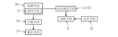
- FIG. 1 is a simplified diagram of a defect inspection apparatus showing a first embodiment of the present invention. It is a simplified block diagram which shows the whole structure of the said defect inspection apparatus. It is a simplified diagram showing a state immediately before sealing, showing an inspection method using the defect inspection apparatus.
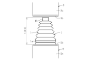
- FIG. 3 is a simplified diagram showing a compressed state, showing an inspection method using the defect inspection apparatus. It is a flowchart figure of the defect inspection method of this invention using the said defect inspection apparatus. It is a graph which shows the internal pressure at the time of a test
- FIG. 1 is a simplified diagram of a defect inspection apparatus showing a first embodiment of the present invention. It is a simplified block diagram which shows the whole structure of the said defect inspection apparatus. It is a simplified diagram showing a state immediately before sealing, showing an inspection method
- FIG. 8 is a simplified plan view of the constant velocity universal joint boot shown in FIG. 7. It is a principal part expanded sectional view of the boot for constant velocity universal joints shown in the said FIG. It is a simplified block diagram of the control part of the defect inspection apparatus shown in the said FIG.
- FIG. 7 is a simplified diagram showing a state immediately before fixing a constant velocity universal joint boot, showing an inspection method using the defect inspection apparatus shown in FIG. 6.
- FIG. 7 is a simplified diagram showing a constant velocity universal joint boot fixing state, showing an inspection method using the defect inspection apparatus shown in FIG. 6.
- It is a simplified diagram of the state which measures the amount of projections of a projection part using a transmission type laser displacement meter. It is a flowchart figure which shows the inspection method of this invention.
- FIG. 19 is an output waveform diagram of transmission laser displacement in the state shown in FIG. 18.
- FIG. 20 is an output waveform diagram of transmission laser displacement in the state shown in FIG. 19.
- FIG. 21 is an output waveform diagram of transmission laser displacement in the state shown in FIG. 20.
- It is a simplified diagram of a reflection type laser displacement meter. It is sectional drawing of the constant velocity universal joint with which the boot for constant velocity universal joints is mounted
- FIG. 1 shows a defect detection apparatus according to the first embodiment.
- This defect detection device is, for example, a device that detects whether or not there is a defect in the constant velocity universal joint boot 1.
- the constant velocity universal joint boot 1 is made of, for example, an elastic member such as rubber or resin, and has a large diameter portion 1a, a small diameter portion 1b, and a bellows portion 1c between the large diameter portion 1a and the small diameter portion 1b. .
- the defect detection apparatus includes an apparatus main body 60 having a mounting table 2 as one pressing member, and a pressing table 3 as the other pressing member disposed above the mounting table 2 so as to face the mounting table 2.
- the mounting table 2 has a table body 2a, and a seal member 2b made of silicon resin or the like is attached to the upper surface of the table body 2a.
- the pressing table 3 has a table body 3a, and a seal member 3b made of silicon resin or the like is attached to the lower surface of the table body 3a.
- the pressing table 3 moves up and down by an elevating mechanism (drive mechanism) (not shown).
- this lifting mechanism can be constituted by a cylinder mechanism or the like.
- the mounting table 2, the pressing table 3, and the like can constitute a sealing means 15 (see FIG. 2) that can seal both the openings 11 and 12 of the boot 1 that is a forming part.
- the pressing table 3 is lowered by a drive mechanism (not shown) to compress the boot 1 in the axial direction as shown in FIG. 3B. That is, the compression unit 16 (see FIG. 2) can be configured by the pressing table 3 and a driving mechanism (not shown).
- the drive mechanism is controlled by the control means 20 of this apparatus.
- the control means 20 can control the vertical position of the pressing table 3, and can maintain the pressing table 3 at a predetermined position.
- the control means 20 can constitute the maintenance means 17.
- the control means 20 can be constituted by a microcomputer or the like.
- this apparatus is provided with an internal pressure measuring means 21 for measuring the internal pressure in the boot 1.
- a pressure sensor 5 arranged in the mounting table 2 is used as shown in FIG.
- the mounting table 2 is provided with a communication path 25 communicating with the opening 11 of the large-diameter portion 1 a of the boot 1, and the sensor 5 is disposed in the communication path 25.
- a determination means 6 is connected to the pressure sensor 5.
- the internal pressure in the boot 1 measured by the pressure sensor 5 is input to the determination means 6.
- a threshold value of the internal pressure preset by the setting unit 22 is input to the determination unit 6.
- the determination means 6 can be configured by a microcomputer similar to the control means 20. Therefore, the determination means 6 may be constituted by a microcomputer separate from the control means 20 or may be constituted by a microcomputer constituting the control means 20.
- the setting means 22 can be configured by an operation panel (keyboard) provided in the apparatus main body 60, and the threshold value can be input via the operation panel.
- the judging means 6 compares the preset internal pressure threshold value with the internal pressure measured by the internal pressure measuring means 21. When the measured internal pressure is lower than the threshold value, a hole is formed and air is leaking. Further, if the measured internal pressure is not lower than the threshold value, no air leakage has occurred.
- a display screen 7 is provided on the apparatus main body 60. That is, the determination result by the determination unit 6 is displayed on the display screen 7. For example, when the measured internal pressure is lower than the threshold value, it is displayed as a defective product (abnormal product), and when the measured internal pressure is not lower than the threshold value, it is displayed as a non-defective product (normal product). When it is determined that the product is defective, an alarm sound may be generated by an alarm device or the like.
- a threshold value is set and input to the determination means 6. This threshold value is set based on the volume of the boot to be detected, the amount of compression being detected, and the like.
- step S1 of FIG. 4 the boot 1 that is a formed part is sealed. That is, as shown in FIG. 1 and FIG. 3A, the large-diameter portion 1 a of the boot 1 is placed on the mounting table 2. Thereafter, the pressing table 3 is lowered. Thus, the boot 1 is held between the mounting table 2 and the pressing table 3. That is, the opening 11 of the large diameter portion 1 a of the boot 1 is sealed by the mounting table 2, and the opening 12 of the small diameter portion 1 b of the boot 1 is sealed by the pressing table 3.
- the pressing table 3 is further lowered to compress the boot 1 as shown in FIG. 3B (step S2).
- the length L in the axial direction of the boot 1 in the free state is L1 (see FIG. 3A)
- the boot 1 is compressed to L2.
- the specified internal pressure is an internal pressure when the boot 1 is compressed to the above-mentioned size in a state where no air leakage occurs.
- the specified internal pressure was reached in about 2 seconds from the start of compression.
- step S4 it is determined whether a predetermined time has elapsed. Then, when the predetermined time has elapsed, the process proceeds to step S5, and the internal pressure of the boot 1 is measured by the pressure sensor 5 which is the internal pressure measuring means 21.
- step S6 it is determined whether or not the measured internal pressure is lower than a threshold value (reference value in FIG. 5).
- a threshold value reference value in FIG. 5
- step S6 if the measured internal pressure is lower than the threshold value, it is determined as an abnormal product (step S7). If the measured internal pressure is not lower than the threshold value in step S6, it is determined as a normal product (step S8).
- the determination result is displayed on the display screen 7. If an alarm device is provided, an alarm sound may be generated when it is determined that the product is defective.
- both the openings 11 and 12 of the formed part can be sealed by the sealing means 15, and the formed part can be compressed in the axial direction by the compression means 16 in this sealed state. .
- the formed component can be increased to the specified internal pressure.
- the internal pressure of the formed part can be measured by the internal pressure measuring means 21 in a state where the internal pressure is increased by compression.
- the threshold set by the setting means 22 and the internal pressure measured by the internal pressure measuring means 21 can be compared by the judging means 6. And when the measured internal pressure is lower than the set threshold value, it is understood that air leakage has occurred, and it is a defective product in which a hole is formed in the formed component. Moreover, when the measured internal pressure is not lower than the set threshold value, it can be seen that no air leakage occurs and the product is a non-defective product.
- the defect of the formed component can be stabilized without the need for a suction mechanism. Can be detected. That is, according to the present invention, defects in formed parts such as the constant velocity universal joint boot 1 can be detected stably and efficiently at low cost. If a measurement is made after a predetermined time has passed without measuring until the predetermined time has elapsed from the time when the pressure is increased to the specified internal pressure, a minute hole will be formed, and the internal pressure will decrease even if it is only a small amount. Even if it is a thing, it can determine with the defect which an internal pressure falls, and can aim at the improvement of detection accuracy.
- the sealing means 15 can be configured with a pair of pressing members, the configuration can be simplified, and the sealing function can be improved by providing the sealing members 2b and 3b. It is possible to effectively prevent air leakage from the openings 11 and 12 and improve detection accuracy.
- the internal pressure measuring means 21 can be configured by including a pressure sensor 5 attached to either one side of the pressing member, and can stably measure the internal pressure and reduce the size of the apparatus.
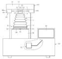
- FIG. 6 shows a defect detection apparatus according to the second embodiment.
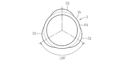
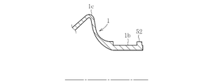
- the large-diameter portion 1a and the small-diameter portion 1b of the constant velocity universal joint boot 1 are provided with a band drop prevention protrusion (protrusion portion) 52 as shown in FIGS.
- the protrusions 52 of the large diameter portion 1a are disposed at a 90 ° pitch along the circumferential direction on the outer diameter of the opening end of the large diameter portion 1a, and the protrusions 52 of the small diameter portion 1b are outside the opening end of the small diameter portion 1b. It arrange
- the defect detection apparatus includes an apparatus main body 60 having a turntable 55 and a pressing member 56 disposed above the turntable 55 so as to face the turntable 55.
- the pressing member 56 moves up and down via a vertical movement mechanism (not shown). Further, the timing and the amount of vertical movement of the pressing member by the vertical movement mechanism are controlled by the control unit 61 that controls the apparatus.
- the large-diameter portion 1a of the constant velocity universal joint boot 1 is placed on the upper surface of the turntable 55, and the fitting shaft portion 58 (see FIG. 11A) is fitted (fitted) into the large diameter portion 1a.
- a pressing shaft 57 is suspended from the lower surface of the pressing member 56.
- the pressing shaft 57 includes a boss portion 57a on the pressing member side and a small-diameter fitting shaft portion 57b protruding from the boss portion 57a. That is, from the state shown in FIG. 11A, as shown in FIG. 11B, the pressing member 56 is lowered as shown by an arrow, so that the constant velocity universal joint boot 1 standing on the upper surface of the turntable 55 is lowered.
- the fitting shaft portion 57b is fitted into the small diameter portion 1b.
- the stepped surface between the boss portion 57 a and the fitting shaft portion 57 b becomes the pressing surface 53 that presses the opening end surface 6 of the small diameter portion 1 b of the boot 1, and the upper surface of the turntable 55 is the large diameter portion 1 a of the boot 1. It becomes the press surface 54 which presses the opening end surface 6 of this.
- this detection device includes a rotation drive mechanism M that rotates the constant velocity universal joint boot 1 around its axis.
- the rotation drive mechanism M is a drive that rotates the rotating table 55 on which the forming component is placed and the constant velocity universal joint boot 1 fixed to the rotating table 55 to rotate around the axis.
- Mechanism (not shown).
- the fixing mechanism 65 includes a pair of pressing surfaces 53 and 54 that contact each opening end surface (the opening end surface 14 of the large-diameter portion 1a and the opening end surface 13 of the small-diameter portion 1b) and sandwich the formed component, and the pressing surfaces 53 and 54.
- a pressing member 56 constituting one pressing surface 53 is moved up and down by a vertical movement mechanism (not shown). Therefore, the shafts 57b and 58 are fitted in the openings and are sandwiched by the pair of pressing surfaces 53 and 54, and can be freely controlled at a position where the protrusion 52 can be detected by the detection means 68 described later.
- the joint boot 1 is held.
- the vertical movement mechanism can be constituted by a cylinder mechanism, a ball nut mechanism, or the like.
- the drive mechanism (not shown) can be composed of a drive motor that is a rotational drive source, a transmission mechanism that transmits the rotational force of the drive motor to the turntable 55, and the like.
- the transmission mechanism can be constituted by a gear mechanism, a belt mechanism, or the like, and a servo motor or the like can be used as the drive motor.
- a detecting means 68 for detecting (measuring) the protrusion amount of the protrusion 52 of the constant velocity universal joint boot 1 is disposed on the pressing member 56 side.
- the detection means 68 can be constituted by a transmission type laser displacement meter 66, for example.
- the transmissive laser displacement meter 66 includes a laser light projector 66a that projects laser light, and a laser light receiver 66b that is disposed opposite to the laser light projector 66a. That is, the band-shaped laser beam L is irradiated from the laser beam projector 66a toward the laser beam receiver 66b, and the laser beam L is blocked by the object to be inspected (the constant velocity universal joint boot 1).
- the amount of protrusion (the amount of protrusion) is measured.
- the laser displacement meter 66 is preferably set so that it can move up and down.
- the control unit of this inspection apparatus includes a data analysis unit 70 that calculates correction data from the measurement data measured by the detection unit 68, and a threshold value that is a set defect determination criterion.
- the first pass / fail judgment means 71 for judging pass / fail by comparing with the corrected data corrected by the data analysis means, and the first for judging whether the slope of the correction data within the set section is normal.
- 2 pass / fail judgment means 72, and a defect judgment means 73 for detecting a defect of the formed part based on the judgments of the first pass / fail judgment means 71 and the second pass / fail judgment means 72.
- the data analysis means 70 corrects errors based on the rotational shake and deformation of the formed parts from the detection values detected by the detection means 68. That is, an FFT analysis is performed on the value output from the laser displacement meter, which is the detecting means 68, and the rotational vibration (for example, the frequency of one cycle / one round of the boot) and the deformation (the frequency of two cycles / one round of the boot) are determined from the analysis result. ) Is removed, and IFFT processing is performed.
- the first pass / fail judgment means 71 sets the threshold based on the difference between the minimum value of the protruding portion and the maximum value of the protruding portion in a normal formed component having no defect, and the protrusion in the formed component of the inspection target product The difference between the minimum measured value of the portion and the maximum measured value of the protrusion is calculated, and this calculated value is compared with the threshold value. Further, the second pass / fail judgment means 72 detects the inclination of the correction data within the set section, and determines a defective product when a different inclination is included.
- the data analysis means 70, the first pass / fail judgment means 71, the second pass / fail judgment means 72, and the defect judgment means 73 can be constituted by a microcomputer or the like. Further, as described above, the control unit 61 can control the vertical movement mechanism and can also perform rotation control of the rotation drive mechanism M.
- a display screen 62 is provided on the apparatus main body 60. That is, the determination result by the defect determination means 73 is displayed on the display screen 62.
- an alarm sound may be generated by an alarm device or the like.
- the threshold value used in the first pass / fail judgment means 71 is set, and the slope of the output waveform used in the second pass / fail judgment means 72 is set.
- the threshold value and the like are input to the pass / fail judgment means 71 and 72 of the control unit 61 via an operation panel (keyboard) provided in the apparatus main body 60.
- the constant velocity universal joint boot 1 is placed on the turntable 55. That is, the constant velocity universal joint boot 1 is erected and supported on the turntable 55 in a state where the shaft portion 58 is fitted in the large diameter portion 1 a of the constant velocity universal joint boot 1.
- the pressing member 56 is raised.
- the pressing member 56 is lowered so that the fitting shaft portion 57 b of the pressing shaft 57 is fitted into the small diameter portion 1 b of the constant velocity universal joint boot 1, and the stepped surface of the pressing shaft 57, that is, the pressing surface 53.
- the opening end of the small-diameter portion 1b of the constant velocity universal joint boot 1 is pressed downward to compress the boot 1 by a predetermined dimension along the axial direction.
- the position where the small diameter portion 1 b corresponds to the laser displacement meter 66 positioned on the upper side, that is, the projection amount of the projection 52 by the laser displacement meter 66 is set as a detectable position.
- the turntable 55 is rotated to rotate the constant velocity universal joint boot 1 on the turntable 55 about its axis.
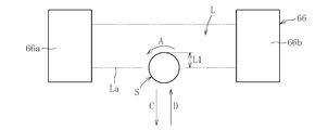
- the projection amount of the projection 52 is detected (measured) by the transmission laser displacement meter 66. That is, as shown in FIG. 12, the constant velocity universal joint boot 1 is supported so that the protrusion 52 is positioned in the belt-shaped laser beam projected from the laser beam projector 66a.
- the projection amount (height) of the projection portion 52 can be measured, and the projection amount (height) of the projection portion 52 is measured as shown in step S11 of FIG.
- the protrusion amount L1 is a dimension from one side edge (side edge) La of the laser light L to the outer edge of the protrusion 52.
- the transmission type laser displacement meter 66 shows a state in which the inspection object S is rotated while being displaced in the directions of arrows C and D, in a state of being eccentric in a perfect circle shape.
- the measurement value L1 is detected at, the output of the measurement value L1 changes.
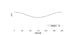
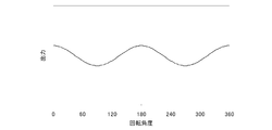
- the waveform draws a curve (curve) as shown in FIG.
- the measured value is measured by the transmission laser displacement meter 66 on the inspection object S rotating in a state of being deformed from a perfect circle (in a state of being deformed into an ellipse). Even when L1 is detected, the output of the measured value L1 changes.
- the waveform draws a sine (cosine) curve as shown in FIG.
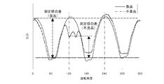
- the value output from the laser displacement meter 66 has a waveform as shown in FIG. 14, for example.
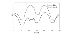
- a solid line indicates a non-defective product that does not have a chip or the like in the protrusion 52
- a one-dot chain line indicates a defective product that has a chip or the like in the protrusion 52.
- the swing of the turntable 55 or the boot 1 is deformed, it is determined that the non-defective product is not defective due to this swing or the like. There is a risk of determining that a defective product is a good product.
- step S11 measurement is started (step S11), and thereafter, the data analysis means 70 corrects the error based on the runout and deformation of the molded part from the detection value detected by the detection means 68. That is, correction data is calculated (step S12).
- every periodic function can be represented by a superposition of cos and sin having an integer multiple of the periodic function.
- l is a positive number
- the Fourier series of the periodic function f (x) having the period 2l is expressed by the following expression 1.
- the Fourier coefficients c 0 , a n , and b n are the following expressions 2, 3, and 4.
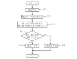
- the first pass / fail judgment means 71 and the second pass / fail judgment means 72 judge pass / fail (step S13). And it is determined whether the judgment of the 1st quality determination means 71 and the determination of the 2nd quality determination means 72 are good (step S14). If the judgment by the first pass / fail judgment means 71 and the second pass / fail judgment means 72 are good, the product is judged as good (step S15). If the judgment is bad, the product is judged as defective (step S16).
- the protrusions 52 are arranged at a pitch of 120 degrees along the circumferential direction on the small diameter portion 1b side of the constant velocity universal joint boot 1, the measured values of the protrusions 52 are measured.
- the minimum and maximum periods are every 120 degrees. For this reason, the difference between the measured value at the minimum position in the normal product and the measured value at the maximum position is obtained, and this difference is used in the first pass / fail judgment means 71. That is, as shown in FIG. 16, in the case of a non-defective product (waveform shown by a one-dot chain line), the maximum output is shown in the case of a non-defective product (waveform shown by a one-dot chain line).
- the difference between the value and the minimum output value is small. For example, if it is less than 60% of the difference in the case of a non-defective product, it can be regarded as a missing defect. Therefore, 60% of the difference in the case of a non-defective product becomes the threshold value of the first quality determination means 71.
- a value below this threshold is regarded as a defective product, and a product exceeding the threshold value is regarded as a good product. Can do.
- the threshold value can be variously changed according to the product type (model number) and the inspection status.
- the second pass / fail judgment means 72 performs a determination in order to detect a chipping or a lack of a wall other than the highest point of the protrusion 52.
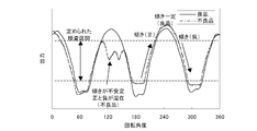
- the second pass / fail judgment means 72 can detect a chipping or a lack of thickness other than the highest point of the protrusion 52 by comparing the slopes of the respective measurement values within the determined measurement value section. That is, in the normal product (non-defective product), as shown in FIG. 15, the slope is “positive” or “negative” and is always constant in the determined output section.
- the inclination within the determined measurement value section is not stable, and “positive” is applied to the inclination. And “negative” are mixed.
- the 2nd quality determination means 72 the inclination of the measured value in the determined measured value area is compared. That is, when the difference value between the maximum value and the minimum value of the measured value is 100%, the lower limit value and the upper limit value of the determined section (inspection section) are set to about ⁇ 40% of the measured value average.
- the defect determination means 73 If the determination result by the defect determination means 73 is bad on the display screen 62, it is displayed as a defective product (abnormal product), and if the determination is good, it is displayed as a good product (normal product). When it is determined that the product is defective, an alarm sound may be generated by an alarm device or the like.
- correction data FFT and IFFT can be used, and the displacement based on the rotational shake and deformation of the formed part can be stably corrected, and high-precision determination can be performed.
- the rotational drive mechanism M includes the fixing mechanism 65
- the rotation of the formed part by the rotational drive mechanism M is stable, and more accurate determination can be performed.
- the fixing mechanism 65 includes the pair of pressing surfaces 53 and 54, more stable rotation can be obtained, and stable quality determination can be performed.
- inspection of the projection part 52 by the side of the small diameter part 1b was performed, the test
- the laser displacement meter may be made to correspond to the protrusion 52 of the large diameter portion 1a.
- the inspection of the protruding portion 52 on the large diameter portion 1a side can be performed using this inspection apparatus.
- a reflection type laser displacement meter 75 as shown in FIG. 24 may be used without using the transmission type laser displacement meter 66.
- the reflection-type laser displacement meter 75 includes a light projecting / receiving unit 78 having a laser projecting unit 76 that projects laser light onto a measurement object and a laser light receiving unit 77 that receives the laser light reflected by the measurement object. It is provided.
- the laser light emitted from the laser light projecting unit 76 is reflected by the measurement object and received by the laser light receiving unit 77, and a spot is formed on the laser light receiving unit 77. Since the spot moves each time the object moves, the amount of displacement up to the object is detected by detecting the position of the spot.
- the projection amount of the projection 52 can be measured as in the case of using the transmission type laser displacement meter 66. Therefore, the reflection type laser displacement meter 75 of FIG. 24 can be used in the inspection method and inspection apparatus of the present invention.
- the defect inspection is performed by the defect inspection apparatus, and a defective product is not shipped. For this reason, it becomes the boot for constant velocity universal joints which can exhibit the stable performance.
- the predetermined time until the internal pressure measurement, the threshold value, and the like can be arbitrarily set. That is, it is sufficient that there is a difference between the internal pressure when no hole is formed and the internal pressure so that it can be determined that air leaks through the hole when the hole is formed.
- the pressure sensor 5 constituting the internal pressure measuring means 21 is provided on the mounting table 2 side.
- the pressure sensor 5 may be provided on the pressing table 3 side.
- the mounting table 2 side when the molded part is compressed, the pressing table 3 side is lowered, but conversely, the mounting table 2 side may be moved up and down, and further, the mounting table 2 And the pressing table 3 may be close to each other.
- the shape and number of the protrusions 52 are not limited to those of the above-described embodiment, and the transmission laser displacement meter 66 is used as the rotation speed of the formed part during inspection.
- the amount of protrusion of the protrusion 52 can be measured by the detecting means 68 such as the above.
- the display screen is provided. However, such a display screen may be omitted, and an alarm may be issued when it is determined that the product is defective.
- the molded part is not limited to the constant velocity universal joint boot, but may be another part such as a light shielding boot for a camera. Further, the molded part is a rubber boot using chloroprene rubber or the like even if it is a resin boot formed of a thermoplastic elastomer such as ester, olefin, urethane, amide, or styrene. Also good.
- Constant velocity universal joints such as fixed constant velocity universal joints that allow only angular displacement (barfield type, undercut free type, etc.), sliding types that allow not only constant angular displacement but also axial displacement, etc. A speed universal joint (double offset type, cross groove type, tripod type, etc.) may be used.
Landscapes
- Physics & Mathematics (AREA)
- General Physics & Mathematics (AREA)
- Examining Or Testing Airtightness (AREA)
Abstract
等速自在継手用ブーツ等の成形部品の欠陥を安定して効率的にしかも安価に検出することができる欠陥検出方法及び欠陥検出装置を提供する。 屈曲及び伸縮可能な蛇腹部1cを備え、軸方向両端部が開口した弾性材料からなる成形部品の欠陥を検査する欠陥検査方法および欠陥検査装置である。成形部品の両開口部11,12を密封した状態で、圧縮手段16にて成形部品に対して軸方向内方に圧縮してこの成形部品内の内圧を規定内圧に高める。この圧縮状態を維持手段17にて所定時間維持する。その後、この圧縮状態のまま成形部品内の内圧を内圧測定手段21にて測定し、この測定した内圧に基づいて成形部品の良否を判断する。
Description
本発明は、樹脂やゴム材料を用いて成形された薄肉部分を有する部品に発生する穴開き欠陥を検出する方法および検査装置に関し、特に、自動車のエンジンの動力をタイヤに伝える働きをする等速自在継手の稼動部をカバーするブーツの製造工程で、薄肉及び異物混入等が原因となり発生する穴開き欠陥の検出方法及び検査装置に関するものである。
一般に、軸線が一致しないで、ある角度をもった二軸の接続には、ユニバーサルジョイント(自在軸継手)が必要であって、このうち、主動軸の角速度を変化なく常に等しい角速度で従動軸に回転を伝える等速ジョイント(等速自在継手)は、車両の駆動系などに多く使用されている。
自動車や産業機械の等速自在継手には、継手内部に封入されるグリースを保持するため、あるいは塵等の進入を防止するためにブーツと称される密封装置が装着される。等速自在継手用ブーツに要求される一般的性質としては、等速自在継手の揺動や摺動の動きに対応する追従性、外界から侵入する粉塵や泥水に対するシール性、及び駆動系から伝達される振動に対する耐衝撃性、さらには、グリースに対する耐油性、耐低温性、耐熱性、耐熱老化性、及び耐摩耗性が要求される。
これらの諸性質の中で、追従性、シール性、耐衝撃性、低コスト性の要求を基本的に満たす材料としては、従来ジエン系ゴムの一つとしてクロロプレンゴムが知られている。また、近年になって、耐衝撃性の向上、使用温度範囲の拡大、さらに軽量化の目的から射出成形が可能な熱可塑性エラストマー、特に耐油性、耐熱老化性に優れたポリエステル系またはポリアミド系のエラストマーが使用される。
熱可塑性ポリエステルエラストマーを使用するブーツ成形体の製造は、一般に、ダイレクト・ブロー法やインジェクション・ブロー法などの吹き込み成形によって行われている。しかし、これらの吹き込み成形法による場合は、次のような問題がある。たとえば、スクリューなどで押し出された筒状パリソンを金型内で膨張させることにより成形品を得るダイレクト・ブロー法の場合、押出しパリソンの肉厚をコントロールするパリソンコントロールを使用しても、なおこの種のジャバラ成形体の成形においては、山部と谷部の肉厚の不均一が発生する。また、溶融樹脂を射出して管状成形体を作り、これに空気を吹き込んで成形体を得るインジェクション・ブロー法の場合でも、やはり成形品内面の寸法精度を上げることは非常に難しい。ここで、ブーツ成形体の肉厚不均一は、機能面において重要な問題であり、耐久寿命に多大の影響を与えるものである。
また、ブーツの肉厚が不均一となることにより穴開き等の不良も発生する可能性が高くなる。穴開き欠陥によるグリースの漏れ及び外界からの異物混入等は等速自在継手そのものの寿命を大幅に低減させる。そこで、ブーツ成形後の外観検査が必須となる。
そして、従来には、このようなブーツ(遮光ブーツ)の検査装置が提案されている(特許文献1)。この特許文献1に記載の検査装置は、画像処理装置を用いて、ブーツ蛇腹部に存在する欠陥を検出するものであって、伸長機構部と、照明光源と、前記画像処理装置と、CCDカメラ等を備えたものである。
すなわち、伸長機構部にて、薄肉のブーツ蛇腹部を伸長させ、この伸長させた状態で、ブーツ内径側から照明光源の照明を蛇腹部に照射し、ブーツの外径側からCCDカメラで蛇腹部を撮像し、この画像を画像処理装置にて処理することになる。また、前記伸長機構部は、回転駆動部を備え、伸長状態にあるブーツをその軸心廻りに回転させることができる。これによって、ブーツの被撮像領域の変更を可能としている。
さらに、伸長機構部は、直動機構と上側吸着部と下側吸着部とを備える。すなわち、上側吸着部にブーツの一方のフランジ部を吸着するとともに、下側吸着部にブーツの他方のフランジ部を吸着し、上方の上側吸着部を上昇させることによって、ブーツ蛇腹部を伸長させるものである。
ところで、等速自在継手用ブーツが装着される等速自在継手は、図25に示すように、内径面81に複数のトラック溝82が円周方向等間隔に軸方向に沿って形成された外側継手部材83と、外径面84に外側継手部材83のトラック溝82と対をなす複数のトラック溝85が円周方向等間隔に軸方向に沿って形成された内側継手部材86と、外側継手部材83のトラック溝82と内側継手部材86のトラック溝85との間に介在してトルクを伝達する複数のボール87と、外側継手部材83の内径面81と内側継手部材36の外径面84との間に介在してボール87を保持するケージ88とを備えている。ケージ88には、ボール87が収容されるポケット89が周方向に沿って複数配設されている。
また、内側継手部材86はシャフト嵌入用孔部90が設けられ、このシャフト嵌入用孔部90の内径面に雌スプライン90aが形成されている。内側継手部材86のシャフト嵌入用孔部90にシャフト91の端部雄スプライン91aが嵌入され、この端部雄スプライン91aが内側継手部材86の雌スプライン90aに嵌合する。
そして、等速自在継手用ブーツ100にて継手内部が密封されて、継手内部には、潤滑剤としてグリースが封入されている。等速自在継手用ブーツ100は、大径部100aと、小径部100bと、大径部100aと小径部100bとを連結する蛇腹部100cとからなる。
大径部100aの外径面には周方向凹溝101が形成され、大径部100aが外側継手部材83の開口部に外嵌された状態で、前記周方向凹溝101にブーツバンド102が装着され、このブーツバンド102にて大径部100aを締め付けることによって、大径部100aを外側継手部材83の開口部に外嵌固定することができる。また、等速自在継手用ブーツ100の小径部100bの外径面には周方向凹溝103が形成され、小径部100bがシャフト91のブーツ装着部91bに外嵌された状態で、前記周方向凹溝103にブーツバンド102が装着され、このブーツバンド102にて小径部100bを締め付けることによって、小径部100bをシャフト91のブーツ装着部91bに外嵌固定することができる。
すなわち、外側継手部材83の開口側においては、開口部外径面とブーツの大径部内径面との幾何公差及びバンド102による締め付けにて固定され、シャフト91のブーツ装着部91b側においては、シャフト91のブーツ装着部91bの外径面とブーツの小径部内径面との幾何公差及びバンド102による締め付けにて固定される。
ところが、等速自在継手の回転、可動部の動き等によって、ブーツバンドが外れるおそれがある。ブーツバンドが外れれば、等速自在継手用ブーツが外れ、グリースの継手外部への流出、粉塵や汚水等の継手内部への侵入が発生することになる。このようなことが生じれば、等速自在継手の寿命の低下を招くことになる。そこで、従来においては、このブーツバンドの外れを防止するために、ブーツ開口部、つまり大径部や小径部に、回転軸と直角をなす外径方向に突出する突起部を設けたものがある(特許文献2)。
しかしながら、このような突起部を形成しようとした場合、前記したように熱可塑性ポリエラストマーを使用するブーツでは、突起部に欠けや欠肉が生じたりするおそれがある。このように突起部に欠けや欠肉が生じた場合、ブーツバンドの外れを招くことになる。そこで、ブーツ成形後の外観検査が必須となる。
ところで、従来には、半導体基板の欠けを検査する検査装置において、レーザ変位センサを用いるものがある(特許文献3)。この特許文献3に記載の検査装置は、円盤状の半導体基板を回転チャックに搭載して、この半導体基板をその中心廻りに回転させる。そして、その状態で、反射型のレーザ変位センサから回転している半導体基板の周端部にレーザ光を照射することによって、半導体基板の周端部に形成された欠けを検出するものである。
前記特許文献1に記載のものでは、画像処理装置及び伸長機構部等を必要として、装置全体が複雑化するとともに、高コスト化していた。また、前記特許文献1は、カメラ等に用いる遮光ブーツである。このブーツの肉厚としては、例えば、数十μm~数百μmである。このため、この特許文献1では、このような肉厚のものを検査することを前提としている。したがって、この特許文献1に記載の構成のものを、肉厚が数百μm~数mm程度の等速自在継手用ブーツに適用させにくい。すなわち、等速自在継手用ブーツでは、蛇腹部を伸長させる際の外力(引張り力)を大とする必要があるからである。
さらに、画像処理装置を用いる場合、欠陥が発生した箇所(部位)やカメラレンズ等に埃等の異物が付着すれば、欠陥が生じているかの判断を正確に行うことができない。すなわち、検査環境によっては、欠陥が生じているにも関わらず、その欠陥を見つけることができないおそれがある。
前記したように、等速自在継手用ブーツにおいて突起部を設けたものでは、突起部に欠けや欠肉が生じていないかブーツ成形後の外観検査が必須となる。しかしながら、目視による外観検査では、突起部の欠けや欠肉等を検出することができるが、作業性が悪く検査に掛かるコストが大となっていた。
前記特許文献2等に記載の検査装置を用いて、突起部を有する等速自在継手用ブーツを検査する場合、回転チャック上に等速自在継手用ブーツを載置し、回転チャックを回転させることによって、等速自在継手用ブーツを回転させることになる。しかしながら、このような検査装置を用いて検査を行えば、この回転しているブーツに対して、レーザ変位センサからレーザ光を照射することになる。
しかしながら、このような装置を用いると、回転チャック(回転台)に等速自在継手用ブーツを保持させた状態で、回転チャックをその軸心廻りに回転させるので、回転台および等速自在継手用ブーツの回転振れや等速自在継手用ブーツの変形等により、レーザ変位センサと等速自在継手用ブーツとの距離が一定に維持できない場合がある。このように、レーザ変位センサと等速自在継手用ブーツとの距離が一定でない場合、良品にかかわらず、不良品と判定したり、逆に、不良品にかかわらず、良品と判定したりするおそれがある。
そこで、本発明は斯かる実情に鑑み、等速自在継手用ブーツ等の成形部品の欠陥を安定して効率的にしかも安価に検出することができる欠陥検出方法及び欠陥検出装置を提供しようとするものである。
本発明の第1の欠陥検出方法は、屈曲及び伸縮可能な蛇腹部を備え、軸方向両端部が開口した弾性材料からなる成形部品の欠陥を検査する欠陥検査方法であって、前記成形部品の両開口部を密封した状態で、成形部品に対して軸方向内方に圧縮してこの成形部品内の内圧を規定内圧に高めた後、この圧縮状態を所定時間維持し、その後、この圧縮状態のまま成形部品内の内圧を測定し、この測定した内圧に基づいて成形部品の良否を判断するものである。
本発明の第1の欠陥検出方法によれば、成形部品に対して軸方向内方に圧縮することによって、成形部品内の内圧を規定内圧に高めることができる。この際、成形部品に微小な穴等が生じていれば、この穴からエアが抜け、形成部品の内圧が低下する。これに対して、微小な穴が生じていなければ、エアが抜けず、形成部品の内圧が低下しない。このため、圧縮状態のまま成形部品内の内圧を測定することによって、この内圧が規定内圧よりも低ければ、エアが抜けていることになって、微小な穴等が生じているとすることができる。これに対して、測定した内圧が規定内圧よりも低くなっていなければ、微小な穴等が生じていないとすることができる。
すなわち、本発明の欠陥検出方法によれば、画像処理装置やCCDカメラや回転駆動装置を必要とせず、しかも、成形部品を圧縮するものであるので、吸着機構を必要とすることなく、成形部品の欠陥を安定して検出することができる。
ところで、微小な穴形成による欠陥では、規定内圧に高めた時点から僅かずつしかエアがぬけない。このため、規定内圧(基準内圧)に高めた時点において内圧を測定し、この測定した内圧を基準として判断した場合、微小な穴が形成されているにも係らず、その測定内圧が、規定内圧(基準内圧)よりも低くならず、欠陥がないと判断するおそれがある。そこで、規定内圧に高めた時点から所定時間を経過するまで、測定せずに、所定時間を経過したのち測定するようにすれば、微小な穴が形成されていれば、僅かずつであっても内圧が低下するので、内圧が低下して欠陥があると判定できる。
本発明の第2の欠陥検出方法は、軸方向両端部に開口部を有し、かつこの開口部に外径側に突出する突起部を設けた弾性材料からなる筒状の成形部品における欠陥を検査する欠陥検査方法であって、軸心廻りに回転している前記成形部品に対してその突起部の突起量を測定した後、その測定した測定データから成形部品の回転振れ及び変形に基づく変位を修正した修正データを算出し、次に、設定された欠陥判断基準となる閾値と前記修正データとを比較する第1良否判断と、設定された区間内での前記修正データの傾きの正常値と比較する第2良否判断とを行い、これらの比較に基づいて成形部品の欠陥を検査するものである。
本発明の第2の欠陥検出方法によれば、欠陥判断基準となる閾値と比較するのは、測定データから成形部品の回転振れ及び変形に基づく変位を修正した修正データであるので、この比較に基づく欠陥判断は精度のよいものとなる。
ところで、修正データのある範囲においては、正常形状の突起部であれば、修正データの波形における傾きは「正」または「負」で一定となる。しかしながら、突起部の一部に欠肉または欠け欠陥等が生じている場合、この傾きが安定せず、傾きが「正」と「負」が混在する波形を得ることになる。このため、修正データの傾きを正規の傾きと比較することにより、欠肉や欠け欠陥等を検出することができる。
修正データを得るには、例えば、前記測定データをFFTした後、定数項及び第1次と第2次の周波数成分の係数を除き、IFFTを行うことにより、成形部品の回転振れ及び変形に基づく変位を修正するようにすればよい。
第1良否判断としては、欠陥を有さない正常状態の成形部品における突起部の最小値と突起部の最大値との差に基づいて前記閾値を設定し、検査対象品の成形部品における突起部の最小の測定値と突起部の最大の測定値との差を算出し、この算出値と前記閾値を比較するものであってもよい。
第2良否判断としては、設定された区間内での修正データの傾きを検出し、異なった傾きが含まれる場合に欠陥品とすることができる。
前記欠陥検査方法を用いて前記等速自在継手用ブーツの欠陥検査を行うことができる。また、等速自在継手用ブーツとして、前記欠陥検査方法を用いて欠陥検査を行ってなるものであってもよい。
また、本発明の第1及び第2の欠陥検出方法における成形部品として等速自在継手用ブーツとすることができる。
本発明の第1の欠陥検出装置は、屈曲及び伸縮可能な蛇腹部を備え、軸方向両端部が開口した弾性材料からなる成形部品の欠陥を検査する欠陥検査装置であって、成形部品の両開口部を密封する密封手段と、成形部品に対して軸方向内方に圧縮してこの成形部品内の内圧を規定内圧に高める圧縮手段と、成形部品内の内圧を測定する内圧測定手段と、欠陥判断基準となる閾値を設定する設定手段と、この設定手段にて設定された閾値と前記内圧測定手段にて測定された内圧とを比較して成形部品の良否を判断する判断手段とを備えたものである。
本発明の第1の欠陥検出装置によれば、密封手段にて成形部品の両開口部を密封することができ、この密封状態で、圧縮手段にて成形部品を軸方向に圧縮することができる。これによって、成形部品を規定内圧に高めることができる。また、圧縮して内圧を高めた状態でこの成形部品の内圧を内圧測定手段にて測定することができる。設定手段にて設定された閾値と前記内圧測定手段にて測定された内圧とを判断手段にて比較することができる。そして、測定された内圧が設定された閾値よりも低い場合、エア漏れが生じていることであり、成形部品に穴が形成された不良品であることがわかる。また、測定された内圧が設定された閾値よりも低くなっていない場合、エア漏れが生じておらず、良品であることがわかる。
圧縮手段による圧縮状態を維持する維持手段を備え、維持手段にて圧縮状態を維持したまま維持開始から所定時間経過後に前記判断手段による良否の判断を行うものであってもよい。すなわち、規定内圧に高めた時点から所定時間を経過するまで、測定せずに、所定時間を経過したのち測定するようにすることができる。このように設定すれば、微小な穴が形成されて、わずかずつであっても内圧が低下するものであっても、内圧が低下する欠陥があると判定できる。
前記密封手段は、成形部品の両開口部をそれぞれ施蓋した状態で挟持する一対の押付部材を備えたもので構成できる。また、各押付部材は、成形部品の開口部開口縁に密接するシール部材を付設するのが好ましい。
圧縮手段は、押付部材を相互に接近させて前記蛇腹部を軸方向に圧縮する駆動機構にて構成することができる。内圧測定手段は、押付部材のいずれか一方側に付設された圧力センサを備えたもので構成できる。
本発明の第2の欠陥検出装置は、軸方向両端部に開口部を有し、かつこの開口部に外径側に突出する突起部を設けた弾性材料からなる筒状の成形部品における欠陥を検査する欠陥検査装置であって、前記成形部品をその軸心廻りに回転させる回転駆動機構と、前記回転駆動機構にてその軸心廻りに回転している成形部品の突起部の突起量を検出する検出手段と、前記検出手段にて検出された検出値から成形部品の回転振れ及び変形に基づく誤差を修正するデータ解析手段と、設定された欠陥判定基準となる閾値と、前記データ解析手段にて修正された修正データとを比較して良否を判断する第1良否判断手段と、設定された区間内での前記修正データの傾きが正常か否かを判断する第2良否判断手段と、前記第1良否判断手段及び第2良否判断手段の判断に基づいて成形部品の欠陥を検出する欠陥判定手段とを備えたものである。
本発明の第2の欠陥検査装置によれば、回転駆動機構にて成形部品をその軸心廻りに回転させることができ、この回転中に、検出手段にて成形部品の開口部の突起部の突起量を検出(測定)することができる。そして、この検出手段にて測定した検出データをデータ解析手段にて修正した修正データを得ることができる。ここで、修正データは、成形部品の回転振れ及び変形に基づく誤差を修正するものである。
第1良否判断手段では、予め設定された欠陥判定基準となる閾値と、前記修正データとを比較して、良否を判断することができる。すなわち、閾値の範囲を越えていれば、不良と判断でき、閾値の範囲内であれば、良品と判断できる。また、第2判断手段では、設定された区間内での修正データの傾きが正常か否かを判定する。すなわち、欠肉や欠け欠陥が形成されている場合、修正データの傾きが「正」と「負」が混在する波形を得ることになる。このため、修正データの傾きを正規の傾きと比較することにより、欠肉や欠け欠陥等を検出することができる。
判定手段では、第1良否判断手段の判断と第2良否判断手段の判断とに基づいて、成形部品が製品として否かを判定することができる。この場合、第1良否判断手段及び第2良否判断手段にて良と判断したものを製品として良とすることができる。
しかも、第1良否判断手段の判断と第2良否判断手段の判断とは、修正データに基づくものであるので、比較に基づく欠陥判断は精度のよいものとなる。
回転駆動機構は、前記成形部品を固定する固定機構を備えたものが好ましい。このように固定機構を備えたものでは、回転駆動機構による成形部品の回転が安定する。
固定機構は、各開口端面に接触して成形部品を挟持する一対の押圧面と、各押圧面から突出して各開口部に嵌合される軸部とを備え、各軸部が開口部に嵌合して一対の押圧面にて挟持された状態で、前記検出手段による突起部の検出が可能な位置で成形部品が保持されるもので構成できる。
前記回転駆動機構は、前記固定機構にて成形部品を保持した状態で成形部品をその軸心廻りに回転させることができる。
前記検出手段に、レーザ光投光部とレーザ光受光部を備え、レーザ光の透過量による変位を測定する透過型レーザ変位計を用いたり、レーザ光投光部からのレーザ光を被検査対象物に投光し、この被検査対象物にて反射されたレーザ光をレーザ光受光部で受けて、反射により変位を測定する反射型レーザ変位計を用いたりできる。
前記成形部品が等速自在継手用ブーツであって、前記欠陥検査装置を用いてこの等速自在継手用ブーツの欠陥検査を行うことができる。このため、本発明の等速自在継手用ブーツは、大径部と、小径部と、大径部と小径部との間の蛇腹部とからなる等速自在継手用ブーツであって、前記成形部品として前記欠陥検査装置にて欠陥の検査が行われたものである。
本発明の等速自在継手用ブーツによれば、前記欠陥検査装置にて欠陥の検査が行われたものであり、不良品が出荷されることがない。
本発明の第1の欠陥検査方法および第1の欠陥検査装置では、等速自在継手用ブーツ等の成形部品の欠陥を安定して効率的にしかも安価に検出することができる。規定内圧に高めた時点から所定時間を経過するまで、測定せずに、所定時間を経過した後、測定するようにすれば、微小な穴(例えば、直径が0.3mm程度の穴)が形成されて、僅かずつであっても内圧が低下するものであっても、内圧が低下する欠陥があると判定でき、検出精度の向上を図ることができる。
密封手段を一対の押付部材を備えたものにて構成でき、構成の簡略化を図ることができ、また、シール部材を付設することによって、密封機能の向上を図ることができ、開口部からのエア漏れを有効に防止して、検出精度の向上を図ることができる。
圧縮手段が押付部材を相互に接近させるものであれば、この圧縮手段の構成の簡略化を図ることができる。内圧測定手段は、前記押付部材のいずれか一方側に付設された圧力センサを備えたもので構成でき、安定した内圧の測定が可能であるとともに、装置のコンパクト化を図ることができる。
本発明の第2の欠陥検査方法および第2の欠陥検査装置では、検査中の回転振れや変形等に影響を受けることなく、定量的に成形部品の両開口部の突起部に発生する欠けや欠肉といった成形不良品の検出が可能となる。
修正データとしては、FFT及びIFFTを用いることができ、成形部品の回転振れ及び変形に基づく変位を安定して修正することができ、高精度の判定を行うことができる。特に、第1良否判断手段の判断と第2良否判断手段の判断とに基づいて良否を判定することができ、高精度の判定を行うことができる。
回転駆動機構が固定機構を備えたものでは、回転駆動機構による成形部品の回転が安定して、より高精度の判定を行うことができる。また、固定機構が一対の押圧面を備えたものでは、より安定した回転を得ることができ、安定した良否判定を行うことができる。
本発明の等速自在継手用ブーツによれば、前記第1の欠陥検査装置や第2の欠陥検査装置にて欠陥の検査が行われたものであり、不良品が出荷されることがない。安定した性能を発揮できる等速自在継手用ブーツとなる。
以下本発明の実施の形態を図1~図24に基づいて説明する。
図1に第1の実施形態の欠陥検出装置を示す。この欠陥検出装置は、例えば、等速自在継手用ブーツ1の欠陥を有するか否かを検出する装置である。等速自在継手用ブーツ1は、例えば、ゴムや樹脂等の弾性部材からなり、大径部1aと、小径部1bと、大径部1aと小径部1bとの間の蛇腹部1cとからなる。
欠陥検出装置は、一方の押付部材としての載置台2を有する装置本体60と、この載置台2に対向して載置台2の上方に配置される他方の押付部材としての押付台3とを備える。この場合、載置台2は台本体2aを有し、この台本体2aの上面にはシリコン樹脂等からなるシール部材2bが付設されている。また、押付台3は台本体3aを有し、この台本体3aの下面にはシリコン樹脂等からなるシール部材3bが付設されている。
また、押付台3は、図示省略の昇降機構(駆動機構)によって上下動する。なお、この昇降機構としては、シリンダ機構等にて構成することができる。このため、載置台2上に大径部1aを載置した状態で、押付台3を下降させれば、載置台2と押付台3とでブーツ1を挟持状とすることができる。このように挟持状とすることによって、載置台2にて大径部1aの開口部11を密封することができるとともに、押付台3にて小径部1bの開口部12を密封することができる。すなわち、シール部材2b、3bが形成部品であるブーツ1の開口部開口縁に密接する。したがって、この載置台2と押付台3等とで、形成部品であるブーツ1の両開口部11,12を密封することができる密封手段15(図2参照)を構成することができる。
そして、前記押付台3は図示省略の駆動機構によって下降することによって、図3Bに示すように、ブーツ1を軸方向に圧縮することができる。すなわち、押付台3と図示省略の駆動機構等で、圧縮手段16(図2参照)を構成することができる。また、駆動機構は、この装置の制御手段20にて制御されることになる。このため、制御手段20が前記押付台3に上下方向位置を制御でき、所定位置で押付台3を維持することができる。このため、制御手段20が維持手段17を構成することができる。なお、制御手段20としては、マイクロコンピュータ等にて構成できる。
ところで、この装置は、図1と図2に示すように、ブーツ1内の内圧を測定する内圧測定手段21が設けられている。この内圧測定手段21としては、図1に示すように、載置台2内に配置される圧力センサ5が用いられる。このため、載置台2には、ブーツ1の大径部1aの開口部11に連通される連通路25が設けられ、この連通路25に前記センサ5が配置される。
そして、この圧力センサ5には判断手段6が接続される。この判断手段6に圧力センサ5にて測定されたブーツ1内の内圧が入力される。また、この判断手段6には、図2に示すように、設定手段22にて予め設定された内圧の閾値が入力される。なお、判断手段6として、前記制御手段20と同様のマイクロコンピュータ等にて構成できる。このため、判断手段6を制御手段20と別のマイクロコンピュータで構成しても、制御手段20を構成するマイクロコンピュータで構成してもよい。また、設定手段22としては、装置本体60に設けられる操作盤(キーボード)等にて構成でき、この操作盤を介して前記閾値を入力できる。
判断手段6では、予め設定された内圧の閾値と、内圧測定手段21にて測定された内圧を比較することになる。そして、測定された内圧が閾値よりも低い場合、穴が形成されてエアが漏れていることになる。また、測定された内圧が閾値よりも低くなければ、エア漏れが生じていないことになる。
このため、この装置では、図1に示すように、装置本体60に表示画面7が設けられている。すなわち、判断手段6による判断結果が表示画面7上に表示される。例えば、測定された内圧が閾値よりも低い場合には、不良品(異常品)として表示され、測定された内圧が閾値よりも低くなければ、良品(正常品)として表示される。なお、不良品であると判断した場合、警報機等にて警報音を発生するようにしてもよい。
次に前記図1と図2に示す欠陥検出装置を用いた欠陥検出方法を、図4に示すフローチャート図等を用いて説明する。まず、閾値を設定して判断手段6に入力しておく。この閾値は、検出するブーツの容積や検出中の圧縮量等に基づいて設定される。
そして、図4のステップS1に示すように形成部品であるブーツ1を密封状態とする。すなわち、図1や図3Aに示すように、ブーツ1の大径部1aを載置台2上に載置する。その後、押付台3を下降させる。これによって、ブーツ1を載置台2と押付台3とで挟持する状態とする。すなわち、ブーツ1の大径部1aの開口部11が載置台2にて密封され、ブーツ1の小径部1bの開口部12が押付台3にて密封される。
この状態からさらに押付台3を下降させて、ブーツ1を図3Bに示すように、圧縮する(ステップS2)。この場合、自由状態のブーツ1の軸方向長さLをL1(図3A参照)とした場合、L2となるまで圧縮する。
すなわち、このように圧縮することによって、ステップS3のように、内圧を規定内圧(図5参照)まで高める。ここで、規定内圧とは、エアもれが生じていない状態で、ブーツ1を前記寸法まで圧縮した際の内圧である。この実施形態では、図5に示すように、圧縮開始から約2秒で、規定内圧に達した。
その後、所定時間その圧縮状態を維持する。すなわち、ステップS4で、所定時間が経過しているかが判断される。そして、所定時間が経過すれば、ステップS5へ移行して、前記内圧測定手段21である圧力センサ5でブーツ1の内圧を測定する。
次に、ステップS6へ移行して、この測定した内圧が閾値(図5の基準値)よりも低いか否かを判断する。そして、ステップS6で、測定した内圧が閾値よりも低い場合は、異常品と判断する(ステップS7)。また、ステップS6で、測定した内圧が閾値よりも低くない場合は、正常品と判断する(ステップS8)。この判断結果が表示画面7に表示される。なお、警報機を備えたものであれば、不良品であると判断した場合に警報音を発生するようにしてもよい。
前記第1の実施形態では、密封手段15にて形成部品の両開口部11,12を密封することができ、この密封状態で、圧縮手段16にて形成部品を軸方向に圧縮することができる。これによって、形成部品を規定内圧に高めることができる。また、圧縮して内圧を高めた状態でこの形成部品の内圧を内圧測定手段21にて測定することができる。設定手段22にて設定された閾値と内圧測定手段21にて測定された内圧とを判断手段6にて比較することができる。そして、測定された内圧が設定された閾値よりも低い場合、エア漏れが生じていることであり、形成部品に穴が形成された不良品であることがわかる。また、測定された内圧が設定された閾値よりも低くなっていない場合、エア漏れが生じておらず、良品であることがわかる。
このため、本実施形態では、画像処理装置やCCDカメラや回転駆動装置を必要とせず、しかも、形成部品を圧縮するものであるので、吸着機構を必要とすることなく、形成部品の欠陥を安定して検出することができる。すなわち、本発明では、等速自在継手用ブーツ1等の形成部品の欠陥を安定して効率的にしかも安価に検出することができる。規定内圧に高めた時点から所定時間を経過するまで、測定せずに、所定時間を経過したのち測定するようにすれば、微小な穴が形成されて、僅かずつであっても内圧が低下するものであっても、内圧が低下する欠陥があると判定でき、検出精度の向上を図ることができる。
密封手段15を一対の押付部材を備えたものにて構成でき、構成の簡略化を図ることができ、また、シール部材2b、3bを付設することによって、密封機能の向上を図ることができ、開口部11,12からのエア漏れを有効に防止して、検出精度の向上を図ることができる。
圧縮手段16が押付部材を相互に接近させるものであれば、この圧縮手段16の構成の簡略化を図ることができる。内圧測定手段21は、前記押付部材のいずれか一方側に付設された圧力センサ5を備えたもので構成でき、安定した内圧の測定が可能であるとともに、装置のコンパクト化を図ることができる。
次に図6は第2の実施形態の欠陥検出装置を示す。この場合の等速自在継手用ブーツ1の大径部1a及び小径部1bには、図7~図9等に示すように、バンド抜け防止用突起(突起部)52が設けられている。大径部1aの突起部52は、大径部1aの開口端外径部に周方向に沿って90°ピッチで配設され、小径部1bの突起部52は、小径部1bの開口端外径部に周方向に沿って120°ピッチで配設される。また、各突起部52は、図8に示すように、円弧状をなす。
欠陥検出装置は、回転台55を有する装置本体60と、この回転台55に対向して回転台55の上方に配置される押付部材56とを備える。押付部材56は図示省略の上下動機構を介して、上下動する。また、この上下動機構による押付部材の上下動のタイミング及び上下動量は、本装置の制御を行う制御部61で制御される。
この場合、回転台55の上面に等速自在継手用ブーツ1の大径部1aが載置され、この載置された状態で、この回転台55の上面から突出した嵌合軸部58(図11A参照)が大径部1aに嵌入(嵌合)する。
また、図11Aと図11Bに示すように、押付部材56の下面には押付軸57が垂下されている。この押付軸57は押付部材側のボス部57aと、このボス部57aから突出される小径の嵌合軸部57bとからなる。すなわち、図11Aに示す状態から、図11Bに示すように、押付部材56を矢印のように、下降させることによって、回転台55の上面に立設されている等速自在継手用ブーツ1に対してその小径部1bに嵌合軸部57bが嵌入することになる。この場合、嵌合軸部57bが小径部1bに嵌入されることによって、ボス部57aと嵌合軸部57bとの間の段付面が小径部1bの開口端に当接する。このため、この当接した状態からさらに押付部材56を下降させると、ブーツ1を軸方向に圧縮することができる。
すなわち、ボス部57aと嵌合軸部57bとの間の段付面がブーツ1の小径部1bの開口端面6を押圧する押圧面53となり、回転台55の上面がブーツ1の大径部1aの開口端面6を押圧する押圧面54となる。
ところで、この検出装置は、等速自在継手用ブーツ1をその軸心廻りに回転させる回転駆動機構Mを備える。この回転駆動機構Mは、形成部品を載置する回転台55と、この回転台55を回転させてこの回転台55に固定されている等速自在継手用ブーツ1を軸心廻りに回転させる駆動機構(図示省略)とを備える。
固定機構65は、各開口端面(大径部1aの開口端面14および小径部1bの開口端面13)に接触して形成部品を挟持する一対の押圧面53,54と、各押圧面53,54から突出して各開口部に嵌合される軸部57b、58等を備え、一方の押圧面53を構成する押付部材56が図示省略の上下動機構にて上下動する。したがって、各軸部57b、58が開口部に嵌合して一対の押圧面53,54にて挟持された状態で、後述する検出手段68による突起部52の検出が可能な位置で等速自在継手用ブーツ1が保持される。なお、上下動機構としては、シリンダ機構やボールナット機構等にて構成できる。
また、前記図示省略の駆動機構は、回転駆動源である駆動用モータと、この駆動用モータの回転力を回転台55に伝達する伝達機構等から構成できる。伝達機構としては、ギア機構やベルト機構等にて構成でき、駆動用モータとしてはサーボモータ等を用いることができる。
このため、図11Bに示すように、固定機構65にて等速自在継手用ブーツ1を固定した状態で、駆動機構を駆動させることによって、回転台55が回転して等速自在継手用ブーツ1がその軸心廻りに回転することになる。
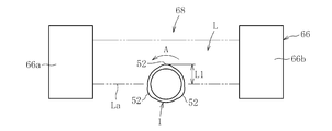
また、図6と図12に示すように、押付部材56側に、等速自在継手用ブーツ1の突起部52の突起量を検出(測定)する検出手段68が配置される。検出手段68は、例えば、透過型レーザ変位計66にて構成できる。透過型レーザ変位計66は、レーザ光を投光するレーザ光投光器66aと、このレーザ光投光器66aに相対向して配設されるレーザ光受光器66bとを備える。すなわち、レーザ光投光器66aからレーザ光受光器66bに向けて帯状のレーザ光Lを照射し、このレーザ光Lを被検査物(等速自在継手用ブーツ1)がさえぎったことで、突起部52の突出量(突起量)を測定するものである。なお、このレーザ変位計66としては、上下動できるように設定するのが好ましい。
ところで、図10に示すように、この検査装置の制御部は、前記検出手段68にて測定された測定データから修正データを算出するデータ解析手段70と、設定された欠陥判定基準となる閾値と、前記データ解析手段にて修正された修正データとを比較して良否を判断する第1良否判断手段71と、設定された区間内での前記修正データの傾きが正常か否かを判定する第2良否判断手段72と、前記第1良否判断手段71及び第2良否判断手段72の判断に基づいて形成部品の欠陥を検出する欠陥判断手段73とを備える。
データ解析手段70は、検出手段68にて検出された検出値から形成部品の回転振れ及び変形に基づく誤差を修正するものである。すなわち、検出手段68であるレーザ変位計より出力された値をFFT解析し、その解析結果から、回転振れ(例えば、1サイクル/ブーツ1周の周波数)と変形(2サイクル/ブーツ1周の周波数)の影響を除去し、IFFT処理するものである。
第1良否判断手段71は、欠陥を有さない正常状態の形成部品における突起部の最小値と突起部の最大値との差に基づいて前記閾値を設定し、検査対象品の形成部品における突起部の最小の測定値と突起部の最大の測定値との差を算出し、この算出値と前記閾値を比較するものである。また、第2良否判断手段72は、設定された区間内での修正データの傾きを検出し、異なった傾きが含まれる場合に欠陥品とするものである。
ところで、データ解析手段70、第1良否判断手段71、第2良否判断手段72、および欠陥判断手段73はマイクロコンピュータ等にて構成できる。また、この制御部61には、前記したように、上下動機構の制御を行うことができるとともに、回転駆動機構Mの回転制御も行うことができる。
この装置では、図6に示すように、装置本体60に表示画面62が設けられている。すなわち、欠陥判断手段73による判断結果が表示画面62上に表示される。なお、不良品であると判断した場合、警報機等にて警報音を発生するようにしてもよい。
次に、前記のように構成された検出装置にて成形部品である等速自在継手用ブーツ1の検査方法を説明する。まず、第1良否判断手段71において用いる閾値を設定するとともに、第2良否判断手段72において用いる出力波形の傾きを設定する。この場合、装置本体60に設けられる操作盤(キーボード)を介して前記閾値等を制御部61の良否判断手段71、72等に入力することになる。
そして、図11Aに示すように、等速自在継手用ブーツ1を回転台55上に載置する。すなわち、等速自在継手用ブーツ1の大径部1aに軸部58を嵌入させた状態で、等速自在継手用ブーツ1を回転台55上に立設支持する。この場合、押付部材56を上昇させておく。次に、押付部材56を下降させて、押付軸57の嵌合軸部57bを等速自在継手用ブーツ1の小径部1bに嵌入させ、押付軸57の段付面、つまり押付面53にて、等速自在継手用ブーツ1の小径部1bの開口端を下方に押圧して、ブーツ1をその軸心方向に沿って所定寸だけ圧縮する。この状態で、上方側に位置しているレーザ変位計66に小径部1bが対応する位置、つまりレーザ変位計66にて突起部52の突起量を検出可能位置とする。
そして、回転台55を回転させてこの回転台55上の等速自在継手用ブーツ1をその軸心廻りに回転させる。この回転中に、透過型レーザ変位計66にて、突起部52の突起量を検出(測定)する。すなわち、図12に示すように、レーザ光投光器66aから投光された帯状のレーザ光内で、突起部52が位置するように等速自在継手用ブーツ1を支持する。この際、等速自在継手用ブーツ1が例えば矢印A方向に回転することにより、突起部52によってレーザ光Lが遮蔽される量が変化する。このため、突起部52の突起量(高さ)を測定することができ、図13のステップS11に示すように、突起部52の突起量(高さ)を測定する。この場合の突起量L1は、レーザ光Lの一方の側縁(側辺)Laから突起部52の外縁までの寸法である。
ところで、図18に示すように、真円形状で偏芯がない状態で回転している被検査物Sを、前記透過型レーザ変位計66にて測定値L1を検出した場合、図21に示すように、その出力は一定となる。
これに対して、図19に示すように、真円形状で偏芯している状態、つまり矢印C、D方向に変位しつつ回転している被検査物Sを、前記透過型レーザ変位計66にて測定値L1を検出した場合、測定値L1の出力は変化する。その波形は、図22に示すように、曲線(カーブ)を描くことになる。
また、図20に示すように、真円形状から変形している状態(楕円形状に変形している状態)で回転している被検査物Sを、前記透過型レーザ変位計66にて測定値L1を検出した場合も、測定値L1の出力は変化する。その波形は、図23に示すように、サイン(コサイン)状カーブを描くことになる。
このため、前記検査装置において、回転台55に振れやブーツ1に変形を有する場合、レーザ変位計66より出力された値は、例えば、図14に示すような波形となる。なお、図14において、実線は突起部52に欠け等を有さない良品を示し、1点鎖線は突起部52に欠け等を有する不良品を示している。この場合、回転台55の振れやブーツ1に変形を有しているものであれば、この振れ等によって、欠肉等を有さない良品を不良品と判定したり、逆に欠肉等を有する不良品を良品と判定したりするおそれがある。
そこで、本発明では、測定を開始し(ステップS11)、その後、データ解析手段70にて、検出手段68にて検出された検出値から成形部品の回転振れ及び変形に基づく誤差を修正する。すなわち、修正データを算出する(ステップS12)。
ところで、一般に、あらゆる周期関数は、その整数倍の周期を有するcosとsinの重ね合わせにより表すことができる。lを正の数とするとき、周期2lの周期関数f(x)のフーリエ級数は次の数1のようになる。

フーリエ係数c0,an、bnは、次の数2、数3、数4である。



そこで、偏芯や変形があるブーツが1周(周期2l=2π)するとき、次の数5及び数6となる周波数成分を除いて(係数an=0及びbn=0とする)、IFFT処理を行う。


これによって、図15に示すように、回転振れおよび変形の影響がない波形の修正データを得ることができる。そして、修正データを得た後は、第1良否判断手段71と第2良否判断手段72にて良否を判断することになる(ステップS13)。そして、第1良否判断手段71の判断と第2良否判断手段72の判断とが良か否かを判定する(ステップS14)。そして、第1良否判断手段71の判断と第2良否判断手段72とが良の場合、良品とし(ステップS15)、不良であれば、不良品とする(ステップS16)。
すなわち、欠陥の無い正常品では、等速自在継手用ブーツ1の小径部1b側においては、突起部52が周方向に沿って120度ピッチで配設されているので、突起部52の測定値が最小と最大となる周期は120度毎である。このため、正常品で最小となる位置での測定値と、最大となる位置での測定値との差を求め、この差を第1良否判断手段71において用いる。すなわち、図16に示すように、良品の場合(実線で示す波形)の、最大出力値と最小出力値との差に対して、不良品の場合(1点鎖線で示す波形)は、最大出力値と最小出力値との差が小となっている。例えば、良品である場合の差の60%を下回る場合、欠肉欠陥とすることができる。このため、良品である場合の差の60%が第1良否判断手段71の閾値となって、第1良否判断手段71において、この閾値以下を不良品とし、閾値を越えるものを良品とすることができる。なお、閾値は製品の種類(型番)や検査状況に応じて種々変更することができる。
しかしながら、第1良否判断手段71の判断のみでは、各突起部52の最高点に発生する欠肉欠陥の検出が可能であるが、他の部位に発生する欠けや欠肉を検出することが困難である。そこで、突起部52の最高点以外に発生する欠けや欠肉を検出するために、第2良否判断手段72の判断を行うことになる。
第2良否判断手段72では、定められた測定値区間内の各測定値の傾きを比較することにより、突起部52の最高点以外に発生する欠けや欠肉を検出することができる。すなわち、正常品(良品)では、図15に示すように、定められた出力区間では、傾きが「正」又は「負」で常に一定である。
突起部52の最高点以外に欠けや欠肉が発生していれば、図17の1点鎖線で示すように、定められた測定値区間内での傾きは安定せず、傾きに「正」と「負」とが混在する波形が得られる。このため、第2良否判断手段72においては、定められた測定値区間内の測定値の傾きを比較することになる。すなわち、測定値の最大値と最小値の差値を100%とした場合、定める区間(検査区間)の下限値および上限値は、測定値平均の±40%程度に設定する。
欠陥判断手段73による判定結果が表示画面62上、判定が不良であれば、不良品(異常品)として表示され、判定が良であれば、良品(正常品)として表示される。なお、不良品であると判断した場合、警報機等にて警報音を発生するようにしてもよい。
本発明では、検査中の回転振れや変形等に影響を受けることなく、定量的に成形部品の両開口部の突起部52に発生する欠けや欠肉といった成形不良品の検出が可能となる。
修正データとしては、FFT及びIFFTを用いることができ、形成部品の回転振れ及び変形に基づく変位を安定して修正することができ、高精度の判定を行うことができる。特に、第1良否判断手段71の判断と第2良否判断手段72の判断とに基づいて良否を判定することができ、高精度の判定を行うことができる。
回転駆動機構Mが固定機構65を備えたものでは、回転駆動機構Mによる形成部品の回転が安定して、より高精度の判定を行うことができる。また、固定機構65が一対の押圧面53,54を備えたものでは、より安定した回転を得ることができ、安定した良否判定を行うことができる。
ところで、前記実施形態では、小径部1b側の突起部52の検査を行っていたが、大径部1a側の突起部52の検査も行うことができる。この場合、レーザ変位計を、大径部1aの突起部52に対応させればよい。このため、小径部1b側の突起部52の検査と同様にこの検査装置を用いて大径部1a側の突起部52の検査を行うことができる。
また、検出手段68としては、透過型レーザ変位計66を用いることなく、図24に示すような反射型レーザ変位計75を用いてもよい。反射型レーザ変位計75は、レーザ光を測定対象物に投光するレーザ投光部76と、測定対象物にて反射されたレーザ光を受けるレーザ光受光部77とを有する投受光部78を備えたものである。レーザ投光部76から照射されたレーザ光が測定対象物に反射されてレーザ光受光部77にて受光され、このレーザ光受光部77上にスポットを結ぶ。そして、対象物が移動するごとにスポットも移動するので、そのスポットの位置を検出することで、対象物までの変位量を検出するものである。
従って、このような反射型レーザ変位計75を用いても透過型レーザ変位計66を用いた場合と同様、突起部52の突起量を測定できる。このため、本発明の検査方法及び検査装置に図24の反射型レーザ変位計75を用いることができる。
このように、本発明の等速自在継手用ブーツ1によれば、前記欠陥検査装置にて欠陥の検査が行われたものであり、不良品が出荷されることがない。このため、安定した性能を発揮できる等速自在継手用ブーツとなる。
以上、本発明の実施形態につき説明したが、本発明は前記実施形態に限定されることなく種々の変形が可能であって、例えば、図1に示す第1の欠陥検査装置において、規定内圧や内圧測定までの所定時間や閾値等は任意で設定できる。すなわち、穴が形成されていない時の内圧と、穴が形成されてこの穴を介したエア漏れと判断できる程度の内圧差があればよい。
内圧測定手段21を構成する圧力センサ5を、前記図1に示す実施形態では、載置台2側に設けていたが、他の実施形態として、押付台3側に設けてもよい。また、成形部品を圧縮する際、前記実施形態では、押付台3側を下降させるものであったが、逆に、載置台2側を上昇降させるようにしてもよく、さらには、載置台2と押付台3との両者を相互に接近させるものであってもよい。
図6に示す第2の欠陥検査装置において、例えば、突起部52の形状及び数は、前記実施形態のものに限定されず、検査中における形成部品の回転速度としては、透過型レーザ変位計66等の検出手段68にて突起部52の突起量を測定できる範囲で種々変更できる。なお、前記各実施形態では、表示画面を備えたものであったが、このような表示画面を省略して、不良品と判断した場合に警報機によって警報するものであってもよい。
成形部品としては、等速自在継手用ブーツに限るものではなく、カメラ用の遮光ブーツ等の他の部品であってよい。また、成形部品は、エステル系、オレフィン系、ウレタン系、アミド系、スチレン系等の熱可塑性エラストマーにて形成される樹脂製ブーツであっても、クロロプレンゴム等を使用したゴム製ブーツであってもよい。等速自在継手は、角度変位のみを許容する固定式等速自在継手(バーフィールド型やアンダーカットフリー型等)であっても、等角度変位のみならず軸方向変位も許容する摺動式等速自在継手(ダブルオフセット型やクロスグルーブ型やトリポード型等)であってもよい。
1 等速自在継手用ブーツ
1b 小径部
1a 大径部
1c 蛇腹部
2b、3b シール部材
5 圧力センサ
6 判断手段
7 表示画面
11,12 開口部
15 密封手段
16 圧縮手段
17 維持手段
20 制御手段
21 内圧測定手段
22 設定手段
52 突起部
53,54 押圧面
57b、58 嵌合軸部
60 装置本体
65 固定機構
66 レーザ変位計
68 検出手段
70 データ解析手段
71 第1良否判断手段
72 第2良否判断手段
73 欠陥判断手段
75 反射型レーザ変位計
76 レーザ投光部
77 レーザ光受光部
L レーザ光
M 回転駆動機構
1b 小径部
1a 大径部
1c 蛇腹部
2b、3b シール部材
5 圧力センサ
6 判断手段
7 表示画面
11,12 開口部
15 密封手段
16 圧縮手段
17 維持手段
20 制御手段
21 内圧測定手段
22 設定手段
52 突起部
53,54 押圧面
57b、58 嵌合軸部
60 装置本体
65 固定機構
66 レーザ変位計
68 検出手段
70 データ解析手段
71 第1良否判断手段
72 第2良否判断手段
73 欠陥判断手段
75 反射型レーザ変位計
76 レーザ投光部
77 レーザ光受光部
L レーザ光
M 回転駆動機構
Claims (21)
- 屈曲及び伸縮可能な蛇腹部を備え、軸方向両端部が開口した弾性材料からなる成形部品の欠陥を検査する欠陥検査方法であって、
前記成形部品の両開口部を密封した状態で、成形部品に対して軸方向内方に圧縮してこの成形部品内の内圧を規定内圧に高めた後、この圧縮状態を所定時間維持し、その後、この圧縮状態のまま成形部品内の内圧を測定し、この測定した内圧に基づいて成形部品の良否を判断することを特徴とする欠陥検査方法。 - 軸方向両端部に開口部を有し、かつこの開口部に外径側に突出する突起部を設けた弾性材料からなる筒状の成形部品における欠陥を検査する欠陥検査方法であって、
軸心廻りに回転している前記成形部品に対してその突起部の突起量を測定した後、その測定した測定データから成形部品の回転振れ及び変形に基づく変位を修正した修正データを算出し、次に、設定された欠陥判断基準となる閾値と前記修正データとを比較する第1良否判断と、設定された区間内での前記修正データの傾きに基づく第2良否判断とを行い、これらの判断に基づいて成形部品の欠陥を検査することを特徴とする欠陥検査方法。 - 前記測定データをFFTした後、定数項及び第1次と第2次の周波数成分の係数を除き、IFFTを行うことにより、成形部品の回転振れ及び変形に基づく変位を修正して前記修正データを算出することを特徴とする請求項2に記載の欠陥検査方法。
- 第1良否判断は、欠陥を有さない正常状態の成形部品における突起部の最小値と突起部の最大値との差に基づいて前記閾値を設定し、検査対象品の成形部品における突起部の最小の測定値と突起部の最大の測定値との差を算出し、この算出値と前記閾値を比較することを特徴とする請求項2又は請求項3に記載の欠陥検査方法。
- 第2良否判断は、設定された区間内での修正データの傾きを検出し、異なった傾きが含まれる場合に欠陥品とすることを特徴とする請求項2~請求項4のいずれか1項に記載の欠陥検査方法。
- 前記成形部品が等速自在継手用ブーツであることを特徴とする請求項1~請求項5のいずれか1項に記載の欠陥検査方法。
- 前記請求項1~請求項5のいずれか1項に記載の欠陥検査方法を用いて欠陥検査を行ってなることを特徴とする等速自在継手用ブーツ。
- 屈曲及び伸縮可能な蛇腹部を備え、軸方向両端部が開口した弾性材料からなる成形部品の欠陥を検査する欠陥検査装置であって、
成形部品の両開口部を密封する密封手段と、成形部品に対して軸方向内方に圧縮してこの成形部品内の内圧を規定内圧に高める圧縮手段と、成形部品内の内圧を測定する内圧測定手段と、欠陥判断基準となる閾値を設定する設定手段と、この設定手段にて設定された閾値と前記内圧測定手段にて測定された内圧とを比較して成形部品の良否を判断する判断手段とを備えたことを特徴とする欠陥検査装置。 - 圧縮手段による圧縮状態を維持する維持手段を備え、維持手段にて圧縮状態を維持したまま維持開始から所定時間経過後に前記判断手段による良否の判断を行うことを特徴とする請求項8に記載の欠陥検査装置。
- 前記密封手段は、成形部品の両開口部をそれぞれ施蓋した状態で挟持する一対の押付部材を備えたことを特徴とする請求項8又は請求項9に記載の欠陥検査装置。
- 各押付部材は、成形部品の開口部開口縁に密接するシール部材が付設されていることを特徴とする請求項10に記載の欠陥検査装置。
- 内圧縮手段は、押付部材を相互に接近させて前記蛇腹部を軸方向に圧縮する駆動機構にて構成することを特徴とする請求項8~請求項11のいずれか1項に記載の欠陥検査装置。
- 内圧測定手段は、前記押付部材のいずれか一方側に付設された圧力センサを備えていることを特徴とする請求項8~請求項12のいずれか1項に欠陥検査装置。
- 軸方向両端部に開口部を有し、かつこの開口部に外径側に突出する突起部を設けた弾性材料からなる筒状の成形部品における欠陥を検査する欠陥検査装置であって、
前記成形部品をその軸心廻りに回転させる回転駆動機構と、
前記回転駆動機構にてその軸心廻りに回転している成形部品の突起部の突起量を測定する検出手段と、
前記検出手段にて測定された測定値から成形部品の回転振れ及び変形に基づく変位を修正するデータ解析手段と、
設定された欠陥判定基準となる閾値と、前記データ解析手段にて修正された修正データとを比較して良否を判断する第1良否判断手段と、
設定された区間内での前記修正データの傾きが正常か否かを判断する第2良否判断手段と、
前記第1良否判断手段及び第2良否判断手段の判断に基づいて成形部品の欠陥を検出する欠陥判定手段とを備えたことを特徴とする欠陥検査装置。 - 前記回転駆動機構は、前記成形部品を固定する固定機構を備えたことを特徴とする請求項14に記載の欠陥検査装置。
- 固定機構は、各開口端面に接触して成形部品を挟持する一対の押圧面と、各押圧面から突出して各開口部に嵌合される軸部とを備え、各軸部が開口部に嵌合して一対の押圧面にて挟持された状態で、前記検出手段による突起部の検出が可能位置で成形部品が保持されることを特徴とする請求項15に記載の欠陥検査装置。
- 前記回転駆動機構は、前記固定機構にて成形部品を保持した状態で成形部品をその軸心廻りに回転させることを特徴とする請求項15又は請求項16に記載の欠陥検査装置。
- 前記検出手段に、レーザ光投光部とレーザ光受光部を備え、レーザ光の透過量による変位を測定する透過型レーザ変位計を用いることを特徴とする請求項14~請求項17のいずれか1項に記載の欠陥検査装置。
- 前記検出手段に、レーザ光投光部からのレーザ光を被検査対象物に投光し、この被検査対象物にて反射されたレーザ光をレーザ光受光部で受けて、反射により変位を測定する反射型レーザ変位計を用いることを特徴とする請求項14~請求項17のいずれか1項に記載の欠陥検査装置。
- 前記成形部品が等速自在継手用ブーツであることを特徴とする請求項8~請求項19のいずれか1項に記載の欠陥検査装置。
- 大径部と、小径部と、大径部と小径部との間の蛇腹部とからなる等速自在継手用ブーツであって、前記成形部品として前記請求項8~請求項19のいずれか1項に記載の欠陥検査装置にて欠陥の検査が行われたことを特徴とする等速自在継手用ブーツ。
Applications Claiming Priority (4)
| Application Number | Priority Date | Filing Date | Title |
|---|---|---|---|
| JP2011012120A JP5726547B2 (ja) | 2011-01-24 | 2011-01-24 | 欠陥検査方法および欠陥検査装置 |
| JP2011-012120 | 2011-01-24 | ||
| JP2011041861A JP2012177662A (ja) | 2011-02-28 | 2011-02-28 | 欠陥検査方法および欠陥検査装置 |
| JP2011-041861 | 2011-02-28 |
Publications (1)
| Publication Number | Publication Date |
|---|---|
| WO2012102074A1 true WO2012102074A1 (ja) | 2012-08-02 |
Family
ID=46580647
Family Applications (1)
| Application Number | Title | Priority Date | Filing Date |
|---|---|---|---|
| PCT/JP2012/050344 Ceased WO2012102074A1 (ja) | 2011-01-24 | 2012-01-11 | 欠陥検査方法および欠陥検査装置 |
Country Status (1)
| Country | Link |
|---|---|
| WO (1) | WO2012102074A1 (ja) |
Cited By (1)
| Publication number | Priority date | Publication date | Assignee | Title |
|---|---|---|---|---|
| CN118242978A (zh) * | 2024-03-28 | 2024-06-25 | 中国人民解放军陆军工程大学 | 一种带有定心修正的身管内膛检测装置 |
Citations (3)
| Publication number | Priority date | Publication date | Assignee | Title |
|---|---|---|---|---|
| JPS49120284U (ja) * | 1973-02-09 | 1974-10-15 | ||
| JP2000258286A (ja) * | 1999-03-09 | 2000-09-22 | Fuji Photo Film Co Ltd | 容器の気密性検査装置 |
| JP2004279401A (ja) * | 2003-02-27 | 2004-10-07 | Hitachi Metals Ltd | 2重可撓管の内管の気密検査方法 |
-
2012
- 2012-01-11 WO PCT/JP2012/050344 patent/WO2012102074A1/ja not_active Ceased
Patent Citations (3)
| Publication number | Priority date | Publication date | Assignee | Title |
|---|---|---|---|---|
| JPS49120284U (ja) * | 1973-02-09 | 1974-10-15 | ||
| JP2000258286A (ja) * | 1999-03-09 | 2000-09-22 | Fuji Photo Film Co Ltd | 容器の気密性検査装置 |
| JP2004279401A (ja) * | 2003-02-27 | 2004-10-07 | Hitachi Metals Ltd | 2重可撓管の内管の気密検査方法 |
Cited By (1)
| Publication number | Priority date | Publication date | Assignee | Title |
|---|---|---|---|---|
| CN118242978A (zh) * | 2024-03-28 | 2024-06-25 | 中国人民解放军陆军工程大学 | 一种带有定心修正的身管内膛检测装置 |
Similar Documents
| Publication | Publication Date | Title |
|---|---|---|
| US12330242B2 (en) | Weld bead inspection apparatus | |
| KR20160021815A (ko) | 타이어 생산 라인에서 타이어를 제어하는 기기 및 방법 | |
| KR20090088722A (ko) | 기어 형상 검사장치 | |
| JP2012177662A (ja) | 欠陥検査方法および欠陥検査装置 | |
| KR102386682B1 (ko) | 음료병의 리크 검사장치 및 비젼검사방법 | |
| KR101955204B1 (ko) | 나사산 검사유닛 및 이를 구비한 검사장치 및 검사장치를 이용한 검사방법 | |
| US6293151B1 (en) | Ball bearing inspection apparatus | |
| CN112697434B (zh) | 一种智能主轴的轴承故障检测方法以及系统 | |
| WO2016117244A1 (ja) | 容器の肉厚検査装置 | |
| JP2008286302A (ja) | ロータリージョイントおよび回転弁体の異常検出機構 | |
| JPS63191007A (ja) | ネジの検査測定方法 | |
| JP5726547B2 (ja) | 欠陥検査方法および欠陥検査装置 | |
| JP2015172552A (ja) | ゴムの摩擦係数評価方法 | |
| JP2024155070A (ja) | メカニカルシール保全装置、メカニカルシール保全用部材、及びメカニカルシール保全方法 | |
| JP6926902B2 (ja) | ロボットの異常判定装置 | |
| CN115966494B (zh) | 传送装置及晶圆制作设备 | |
| US20060037415A1 (en) | Continuously variable transmission belt inspection method and inspection device thereof | |
| WO2005047815A1 (ja) | 雄ネジの外観検査装置 | |
| JP4668019B2 (ja) | 圧縮機検査装置 | |
| JP6926904B2 (ja) | ロボットの異常判定装置 | |
| JPH05126628A (ja) | 振動測定装置 | |
| EP3563137B1 (en) | Method for checking tyres | |
| JPH03194406A (ja) | 物体の端部位置検出装置 | |
| JP2604099Y2 (ja) | 成形品の検査装置 | |
| JP2000162149A (ja) | 回転シールの検査装置と検査方法 |
Legal Events
| Date | Code | Title | Description |
|---|---|---|---|
| 121 | Ep: the epo has been informed by wipo that ep was designated in this application |
Ref document number: 12739342 Country of ref document: EP Kind code of ref document: A1 |
|
| NENP | Non-entry into the national phase |
Ref country code: DE |
|
| 122 | Ep: pct application non-entry in european phase |
Ref document number: 12739342 Country of ref document: EP Kind code of ref document: A1 |