WO2012095950A1 - 冷却器 - Google Patents
冷却器 Download PDFInfo
- Publication number
- WO2012095950A1 WO2012095950A1 PCT/JP2011/050305 JP2011050305W WO2012095950A1 WO 2012095950 A1 WO2012095950 A1 WO 2012095950A1 JP 2011050305 W JP2011050305 W JP 2011050305W WO 2012095950 A1 WO2012095950 A1 WO 2012095950A1
- Authority
- WO
- WIPO (PCT)
- Prior art keywords
- refrigerant
- cooler
- inflow side
- region
- refrigerant reservoir
- Prior art date
Links
Images


Classifications
-
- F—MECHANICAL ENGINEERING; LIGHTING; HEATING; WEAPONS; BLASTING
- F28—HEAT EXCHANGE IN GENERAL
- F28F—DETAILS OF HEAT-EXCHANGE AND HEAT-TRANSFER APPARATUS, OF GENERAL APPLICATION
- F28F27/00—Control arrangements or safety devices specially adapted for heat-exchange or heat-transfer apparatus
- F28F27/02—Control arrangements or safety devices specially adapted for heat-exchange or heat-transfer apparatus for controlling the distribution of heat-exchange media between different channels
-
- H—ELECTRICITY
- H01—ELECTRIC ELEMENTS
- H01L—SEMICONDUCTOR DEVICES NOT COVERED BY CLASS H10
- H01L23/00—Details of semiconductor or other solid state devices
- H01L23/34—Arrangements for cooling, heating, ventilating or temperature compensation ; Temperature sensing arrangements
- H01L23/46—Arrangements for cooling, heating, ventilating or temperature compensation ; Temperature sensing arrangements involving the transfer of heat by flowing fluids
- H01L23/473—Arrangements for cooling, heating, ventilating or temperature compensation ; Temperature sensing arrangements involving the transfer of heat by flowing fluids by flowing liquids
-
- H—ELECTRICITY
- H05—ELECTRIC TECHNIQUES NOT OTHERWISE PROVIDED FOR
- H05K—PRINTED CIRCUITS; CASINGS OR CONSTRUCTIONAL DETAILS OF ELECTRIC APPARATUS; MANUFACTURE OF ASSEMBLAGES OF ELECTRICAL COMPONENTS
- H05K7/00—Constructional details common to different types of electric apparatus
- H05K7/20—Modifications to facilitate cooling, ventilating, or heating
- H05K7/2089—Modifications to facilitate cooling, ventilating, or heating for power electronics, e.g. for inverters for controlling motor
- H05K7/20927—Liquid coolant without phase change
-
- H—ELECTRICITY
- H01—ELECTRIC ELEMENTS
- H01L—SEMICONDUCTOR DEVICES NOT COVERED BY CLASS H10
- H01L2924/00—Indexing scheme for arrangements or methods for connecting or disconnecting semiconductor or solid-state bodies as covered by H01L24/00
- H01L2924/0001—Technical content checked by a classifier
- H01L2924/0002—Not covered by any one of groups H01L24/00, H01L24/00 and H01L2224/00
Definitions
- the present invention relates to a cooler, and more particularly to an improvement in refrigerant flow rate.
- a drive device that includes a motor, a drive device case that houses the motor, and an inverter that controls the motor has been proposed that has a cooling structure for cooling the inverter and the motor.
- FIG. 19 and FIG. 20 show a conventional cooler structure disclosed in Patent Document 1 below.
- 18 is an overall perspective view of the cooling structure
- FIG. 19 is a longitudinal sectional view of the cooling structure
- FIG. 20 is a longitudinal sectional view of the main part of the cooling structure.
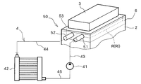
- the heat radiated by the heat radiating body such as the inverter 3 and the electric motor 1 is radiated to the refrigerant circulating in the refrigerant circulation path 4 with the radiator 42 to thermally protect the heat radiating body.
- the inverter 3 includes a switching transistor that converts direct current of the battery power source into alternating current, an accompanying circuit element, and a circuit board on which these are arranged.
- the inverter 3 is attached to the upper surface side of the heat sink 53 integrated with the substrate by attaching the substrate itself or another member to the substrate, and the heat sink 53 is fixed to the bottom of the inverter case 7 that accommodates the inverter 3.
- the lower surface of the heat sink 53 is formed as a heat radiating surface 53 a thermally connected to the inverter 3.
- the inverter case 7 is formed so as to cover the internal inverter 3 to protect it from rainwater and dust.
- the electric motor 1 is accommodated in a drive device case 2, and a spacer member 6 is provided on the upper surface of the drive device case 2.
- a facing surface 6 a that is disposed to face the heat radiating surface 53 a and is thermally connected to the electric motor 1 is formed.
- a rectangular recess for forming the refrigerant space R is formed between the lower surface of the heat sink 53, that is, the heat radiating surface 53a in a state where the heat sink 53 is mounted on the spacer member 6. .
- the bottom surface of the recess forms a facing surface 6a.
- a concave portion 61 that forms the inflow side refrigerant passage Ri and a concave portion 62 that forms the outflow side refrigerant passage Ro are formed in parallel to each other.
- a refrigerant space R is formed between the heat radiating surface 53a of the heat sink 53 and the opposing surface 6a of the spacer member 6, and a plurality of the cooling spaces R are erected from the heat radiating surface 53a toward the opposing surface 6a.
- the heat dissipating fins 56 are arranged in parallel to form an inter-fin passage Rp through which the refrigerant flows between adjacent ones of the heat dissipating fins 56.
- the heat radiating fins 56 extend from the heat radiating surface 53a on the heat sink 53 side toward the facing surface 6a of the spacer member 6 in the refrigerant space R to cross the refrigerant space R in the thickness direction in order to secure a heat exchange area. .
- the heat radiating fins 56 are formed by shaving the lower side of the heat sink 53, and the heat radiating surface 53a is close to the inverter 3 side.
- the length of the distal end portion of the radiating fin 56 is set to be shorter than the length of the base end portion with respect to the portion erected from the surface before shaving and the end surface of the inter-fin passage Rp is radiated by the fin. Inclined with respect to 56 standing directions.
- the inflow-side refrigerant reservoir Ri is formed to extend in the parallel arrangement direction of the inter-fin passage Rp by the recess 61 of the spacer member 6 and the upper surface of the drive device case 2.
- the outflow side refrigerant reservoir Ro is formed to extend in the direction in which the inter-fin passages Rp are arranged.
- the inflow-side refrigerant reservoir Ri and one end of the inter-fin passage Rp are connected in communication by a constricted portion Rs extending over the juxtaposed region of the inter-fin passage Rp, and the discharge-side refrigerant reservoir Ro and the other end of the inter-fin passage Rp are connected to the fin.
- fins 21 are erected in the inflow side refrigerant reservoir Ri and the outflow side refrigerant reservoir Ro to increase the heat transfer area.
- An inflow side port 51 through which refrigerant flows into the inflow side refrigerant reservoir Ri and an outflow side port 52 through which refrigerant flows out from the outflow side refrigerant reservoir Ro are connected in parallel to one side end of the spacer member 6. Then, the refrigerant supplied to the inflow side refrigerant reservoir Ri by the refrigerant pump 41 provided in the refrigerant circulation path is caused to flow through the plurality of inter-fin passages Rp arranged in parallel via the throttle portion Rs, so that the heat radiation surface 53a. Through this, the inverter 3 is cooled. The refrigerant after cooling the inverter 3 flows out to the outflow side refrigerant reservoir Ro through the throttle portion Rs.
- the throttle portion Rs located upstream of the refrigerant flow in the throttle portion Rs since the refrigerant supplied to the inflow side refrigerant reservoir Ri selectively flows into the inter-fin passage Rp via the throttle portion Rs located upstream of the refrigerant flow in the throttle portion Rs, the throttle located downstream. There may be a problem that the flow rate of the refrigerant flowing through the fin-to-fin passage via the portion Rs becomes relatively small, and air stays at the downstream end of the inflow-side refrigerant reservoir and the cooling performance is deteriorated.
- the object of the present invention is to improve the cooling performance on the downstream side of the inflow side refrigerant reservoir in the cooler in which the inflow side refrigerant reservoir and the outflow side refrigerant reservoir are communicated with the refrigerant passage on the heat radiation surface, that is, the refrigerant space via the throttle portion. There is to make it.
- the present invention is a cooler, wherein a refrigerant space flows through the refrigerant, an inflow side refrigerant reservoir communicating with one end side of the refrigerant space via an inflow side restrictor, and an outflow to the other end side of the refrigerant space.
- An outflow side refrigerant reservoir that communicates with the inflow side refrigerant reservoir, wherein the inflow side refrigerant reservoir and the inflow side throttle portion are formed to extend in a first direction and are supplied to the inflow side refrigerant reservoir.
- An adjusting means for increasing the flow rate of the refrigerant in this region by reducing and adjusting the cross-sectional area of the flow path is formed in a region near the side end.
- the adjusting means is a fin.
- the fin may be a pin fin.
- the pin fin is formed unevenly on the side where the inflow side throttle portion communicates.
- the pin fin is formed such that the fin diameter is relatively large on the side where the inflow side throttle portion communicates.
- the pin fin is formed so as to have a relatively high density on the side where the inflow side throttle portion communicates.
- the adjusting means is a guide formed along the first direction.
- the guide in another embodiment, includes a first portion formed along the first direction, and extends in a direction substantially perpendicular to the first direction to flow the refrigerant downstream. It consists of a second part to be regulated.
- a second adjusting means for reducing and adjusting the flow passage cross-sectional area of the inflow side refrigerant reservoir further upstream than the region near the downstream end.
- the second adjusting means is a fin formed along the first direction.
- third adjusting means for reducing and adjusting the flow passage cross-sectional area of the inflow side refrigerant reservoir between the adjusting means and the second adjusting means.
- the third adjusting means is a convex portion formed in the inflow side refrigerant reservoir.
- the basic configuration of the cooler in the embodiment includes the same parts as those of the conventional cooling structure shown in FIGS. That is, the cooler of the embodiment also forms the refrigerant space R between the heat radiation surface 53 a of the heat sink 53 and the facing surface 6 a of the spacer member 6.
- this refrigerant space R if necessary, a plurality of heat radiation fins 56 erected from the heat radiation surface 53a toward the opposing surface 6a are arranged in parallel, and the refrigerant flows between adjacent ones of the plurality of heat radiation fins 56.
- a fin-to-fin passage Rp may be formed.
- the radiation fins 56 are not essential, and in the embodiment, a configuration without the radiation fins 56 will be described.
- the inflow-side refrigerant reservoir Ri is formed in communication with the refrigerant space R by the recess 61 of the spacer member 6 and the upper surface of the drive device case 2. Further, the outflow side refrigerant reservoir Ro is formed in communication with the refrigerant space R by the recess 62 of the spacer member 6 and the upper surface of the drive device case 2.
- the inflow side refrigerant reservoir Ri and one end of the refrigerant space R are communicated with each other through the throttle portion Rs, and the outflow side refrigerant reservoir Ro and the other end of the refrigerant space are communicated with each other through the throttle portion Rs.
- the inflow side refrigerant reservoir Ri is connected to an inflow side port 51 through which refrigerant flows in, and the outflow side refrigerant reservoir Ro is connected to an outflow side port 52 through which refrigerant flows out.
- the refrigerant supplied to the inflow side refrigerant reservoir Ri by the refrigerant pump 41 provided in the refrigerant circulation path is caused to flow through the refrigerant space R via the throttle portion Rs, so that a heating element such as the inverter 3 is provided via the heat radiating surface 53a. Is cooled.
- the refrigerant after cooling the inverter 3 flows out to the outflow side refrigerant reservoir Ro through the throttle portion Rs.
- the heating element for example, the motor or the reactor, in the drive device case 2 is cooled by the refrigerant flowing through the inflow side refrigerant reservoir Ri.
- the cooler 50 of the embodiment cools the heating element at the upper part of the cooling space R and the heating element at the lower part of the inflow side refrigerant reservoir Ri by the heat sink 53 on the upper surface of the cooling space R.
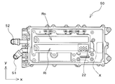
- FIG. 1 shows an overview perspective view of the basic configuration of the cooler 50 in the present embodiment.
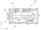
- FIG. 2 shows a plan view of the cooler 50.
- a spacer member 64 corresponding to the spacer member 6 is formed by being divided into three regions 64a, 64b, and 64c in the x direction in the three axes xyz orthogonal to each other. The reason why the spacer member 64 is divided into three corresponds to the fact that the heating element such as the inverter 3 positioned above the cooler 50 is roughly divided into three units.
- An inflow side refrigerant reservoir Ri and an outflow side refrigerant reservoir Ro are formed in the spacer members 64a, 64b and 64c, respectively, and as shown in FIG.
- a portion Rsi is formed and communicates with the inflow side refrigerant reservoir Ri. That is, the throttle portion Rsia is formed at one end of the spacer member 64a, and the throttle portion Rsia communicates with the inflow side refrigerant reservoir Ri. In addition, a throttle part Rsib is formed at one end of the spacer member 64b, and the throttle part Rsib is also in communication with the inflow side refrigerant reservoir Ri. Further, a throttle portion Rsic is formed at one end of the spacer member 64c, and the throttle portion Rsic is also in communication with the inflow side refrigerant reservoir Ri.
- An outflow side throttle portion Rso is formed at the other end of the spacer member 64 in the y direction, and communicates with the outflow side refrigerant reservoir Ro. That is, the throttle part Rsoa is formed at the other end of the spacer member 64a, and the throttle part Rsoa communicates with the outflow side refrigerant reservoir Ro. Further, a throttle portion Rsob is formed at the other end of the spacer member 64b, and the throttle portion Rsob communicates with the outflow side refrigerant reservoir Ro. Further, a throttle portion Rsoc is formed at the other end of the spacer member 64c, and the throttle portion Rsoc is also communicated with the outflow side refrigerant reservoir Ro. In FIG. 2, the refrigerant space R is formed in the upper part (the front side of the paper surface in FIG. 2) of each spacer member 64a, 64b, 64c.
- the inflow side port 51 communicates with one end of the inflow side refrigerant reservoir Ri in the x direction, and the refrigerant is supplied from the inflow side port 51 to the inflow side refrigerant reservoir Ri.
- the refrigerant is arbitrary, for example, cooling water is used.
- the refrigerant supplied to the inflow side refrigerant reservoir Ri flows into the refrigerant space R through the throttle portions Rsia, Rsib, Rsic formed in the three spacer members 64a, 64b, 64c, respectively.
- FIG. 3 shows a schematic perspective view of the cooler 50 with the spacer member 64 removed.
- FIG. 4 is a plan view of the cooler 50 from which the spacer member 64 is removed.
- An inflow side refrigerant reservoir Ri (the bottom surface of the inflow side refrigerant reservoir Ri is shown in the figure) is formed extending along the x direction.
- the outflow side refrigerant reservoir Ro (the bottom surface of the outflow side refrigerant reservoir Ro is shown in the drawing) is also formed to extend along the x direction, and the inflow side refrigerant reservoir Ri and the outflow side refrigerant reservoir Ro are in the y direction. Are arranged side by side.
- Both the inflow-side refrigerant reservoir Ri and the outflow-side refrigerant reservoir Ro are formed in recesses provided side by side in the spacer member 64, and communication holes 51a and 52a for the inflow side port 51 and the outflow side port 52 are formed at one end in the x direction, respectively. Is done.
- the refrigerant flows into the inflow side refrigerant reservoir Ri through the communication holes 51a and 52a, and the cooled refrigerant flows out of the outflow side refrigerant reservoir Ro.
- FIG. 5 and 6 schematically show the flow of the refrigerant that is supplied to the inflow side port 51 and flows out from the outflow side port 52.
- FIG. 5 shows a plan view of the cooler 50 with the spacer member 64 removed
- FIG. 6 shows a plan view of the cooler 50 including the spacer member 64.
- the refrigerant flowing into the inflow side refrigerant reservoir Ri from the inflow side port 51 is 1 ⁇ 2 ⁇ 3 ⁇ 4 according to numerals 1, 2, 3 and 4 in the figure. And flow. That is, the refrigerant flows along the extending direction (x direction) of the inflow side refrigerant reservoir Ri.
- the side communicating with the inflow side port 51 of the inflow side refrigerant reservoir Ri is defined as the upstream side
- the opposite side is defined as the downstream side.
- the refrigerant that has flowed into the inflow side refrigerant reservoir flows into the refrigerant space R through the inflow side throttle portions Rsia, Rsib, and Rsic. That is, a part of the refrigerant flowing into the inflow side refrigerant reservoir Ri is divided and flows into the refrigerant space R through the inflow side throttle portion Rsia of the spacer member 64a. Further, the refrigerant flows into the refrigerant space R through the inflow side restricting portion Rsib of the spacer member 64b. Further, the refrigerant flows into the refrigerant space R through the inflow side restricting portion Rsic of the spacer member 64c. In FIG. 6, these diversion flows are represented as numerals 5, 6, and 7. That is, the refrigerant flowing into the inflow side refrigerant reservoir Ri is 1 ⁇ 2 ⁇ 5 1 ⁇ 2 ⁇ 3 ⁇ 6 1 ⁇ 2 ⁇ 3 ⁇ 4 ⁇ 7 And flow through the refrigerant space R.
- the refrigerant that has flowed through the refrigerant space R and cooled the heating element flows out to the outflow side refrigerant reservoir Ro through the outflow side restricting portions Rsoa, Rsob, Rsoc, and in accordance with numerals 8, 9, 10, 11 in FIG. 8 ⁇ 9 ⁇ 10 ⁇ 11 And flows out from the outflow side port 52.
- FIG. 7 shows a longitudinal sectional view of the cooler 50 at a position where the spacer member 64a is present.
- the spacer member 64a is provided with recesses 61 and 62 arranged side by side in the y direction, and constitutes an inflow side refrigerant reservoir Ri and an outflow side refrigerant reservoir Ro, respectively.
- the refrigerant that has flowed into the inflow-side refrigerant reservoir Ri cools the opposing surface 61 and flows through the refrigerant space R through the inflow-side throttle portion Rsia formed at one end of the spacer member 64a, thereby cooling the heat sink 53.
- the cooled refrigerant flows out to the outflow side refrigerant reservoir Ro through the outflow side throttle portion Rsoa formed at the other end of the spacer member 64a.
- the refrigerant flows through the inflow side throttle portion Rsia located closest to the inflow side port 51 and upstream of the inflow side throttle portions Rsia, Rsib, and Rsic formed in the spacer member 64.
- the basic principle for increasing the flow velocity of the refrigerant in the region near the downstream end of the inflow-side refrigerant reservoir Ri, that is, in the region X, is to allow the refrigerant to flow into the inflow-side restrictor Rsic in the region X, while The purpose is to increase the flow velocity by reducing the cross-sectional area of the flow path.
- adjustment means for reducing and adjusting the channel cross-sectional area is formed in the region X.
- the adjusting means for reducing and adjusting the flow path cross-sectional area is, for example, a fin standing in the region X or a guide standing in the region X.
- FIG. 8 is a schematic perspective view of a cooler 50 according to this embodiment. It is a perspective view of the state which removed the spacer member 64, and respond
- a plurality of non-directional fins for example, pin fins 22, are erected at the downstream end of the inflow-side refrigerant reservoir Ri.
- the pin fins 22 are erected from the bottom surface of the inflow side refrigerant reservoir Ri toward the refrigerant space R.
- FIG. 9 shows a plan view of the cooler 50 shown in FIG.
- the pin fins 22 formed in the region near the downstream end of the inflow side refrigerant reservoir Ri, that is, the region X in FIG. 5 are not formed uniformly in the region X, but one end of the spacer member 64c in the region X. Are unevenly distributed on the side of the inflow side restricting portion Rsic formed in a non-uniform manner. That is, the pin fin 22 is not formed in the region X on the opposite side of the inflow side throttle portion Rsic in the y direction.
- the inflow side refrigerant reservoir Ri is divided into four equal parts in the y direction in the region X, and the pin fins 22 are erected in the region of 3/4 when viewed from the inflow side throttle portion Rsic side, and the remaining 1/4 There are no pin fins 22 in the region.
- the inflow-side refrigerant reservoir Ri is divided into two equal parts in the y direction in the region X, and the pin fins 22 are erected in the 1 ⁇ 2 region as viewed from the inflow-side throttle portion Rsic side, and the remaining
- the pin fins 22 may not be present in the / 2 region, and the inflow side refrigerant reservoir Ri is equally divided into three in the y direction in the region X, and the pin fins 22 are present in the 2/3 region as viewed from the inflow side throttle portion Rsic side.
- the pin fins 22 may not exist in the remaining 1/3 region.
- the pin fins 22 are erected in all of the region X, a configuration in which more pin fins 22 are erected on the inflow side throttle portion Rsic side may be employed.
- the standing density of the pin fins 22 changes along the y direction, and the standing density increases as the distance from the inflow side throttle portion Rsic increases. Since the pin fins 22 are unevenly distributed on the inflow side throttle part Rsic side and are erected unevenly, a difference occurs in the flow velocity of the refrigerant in the region X, and the flow velocity of the refrigerant decreases in the region where the pin fins 22 are erected.
- the refrigerant flow rate is relatively increased.
- FIG. 10 shows the flow of the refrigerant in the inflow side refrigerant reservoir Ri in the present embodiment.
- the refrigerant supplied from the inflow side port 51 flows from the upstream side to the downstream side, and is divided and flows to the inflow side throttle portions Rsia and Rsib. Then, the refrigerant flows into the region X at the downstream end.
- the pin fins 22 are unevenly distributed and are erected, and the flow velocity of the refrigerant is reduced by the pin fins 22, while in the region where the pin fins 22 are not present or the erection density of the pin fins 22 is relatively small, the refrigerant flow velocity. Increases relatively.
- a region where the pin fins 22 are erected or a region where the pin fins 22 are relatively dense is a relatively high pressure loss region, a region where the pin fins 22 are not erected, or the pin fins 22 are relatively dense.
- a relatively small region is a relatively low pressure loss region, and it can be said that the pin fin 22 generates a relatively low pressure loss region and a high pressure loss region in the region X to increase the flow rate of the refrigerant.
- the pin fin 22 reduces the flow path cross-sectional area of the region X and increases the flow rate of the refrigerant in the region X.
- FIG. 11 shows a configuration of a cooler 50 in the present embodiment. It is a top view of the cooler 50 of the state which removed the spacer member 64.
- FIG. A plurality of pin fins 23 are erected in a region near the downstream end of the inflow side refrigerant reservoir Ri, that is, in the region X.
- the pin fins 23 are erected from the bottom surface of the inflow side refrigerant reservoir Ri toward the refrigerant space R. Although the pin fins 23 are erected substantially uniformly in the region X, the fin diameters (diameters) of the fins are not the same.
- the fin diameter of the pin fins 23 is relatively large on the inflow side restricting portion Rsic side, and the fin diameter of the pin fins 23 is relatively small on the side opposite to the inflow side restricting portion Rsic.
- the fin diameter of the pin fins 23 varies along the y direction, and the closer to the inflow side throttle part Rsic, the larger the fin diameter.
- the change in the fin diameter of the pin fins 23 may be continuous or stepwise.
- the flow velocity of the refrigerant changes according to the diameter of the pin fin 23, and the flow velocity of the refrigerant relatively increases in a region where the diameter of the pin fin 23 is relatively small. Therefore, the stagnant air in the region X is effectively discharged, and the cooling performance in the region X is improved.
- the fin diameter of the pin fins 23 changes sequentially in the y direction.
- the fin diameter of the pin fins 23 changes in two stages, and a pin fin with a relatively large fin diameter is located closer to the throttle portion Rsic. 23 may be erected, and a pin fin 23 having a relatively small fin diameter may be erected on the opposite side.
- FIGS. 12 and 13 show a configuration of a cooler 50 in the present embodiment.
- FIG. 12 is a longitudinal sectional view of the cooler 50 at a position where the spacer member 64c exists
- FIG. 13 is a plan view of the state where the spacer member 64 is removed.
- a guide 24 is erected and formed in a region near the downstream end of the inflow side refrigerant reservoir Ri, that is, in a region X.
- the guide 24 is erected from the bottom surface of the inflow side refrigerant reservoir Ri and extends along the extending direction (x direction) of the inflow side refrigerant reservoir Ri.
- the guide 24 does not reach the downstream end of the inflow side refrigerant reservoir Ri, and a space is formed between the guide 24 and the downstream end.
- the guide 24 is erected substantially at the center in the width direction (y direction) of the inflow side refrigerant reservoir Ri, and divides the refrigerant flow path in the region X into two.
- the guide 24 is erected from the bottom surface of the inflow side refrigerant reservoir Ri toward the refrigerant space R, and does not reach the spacer member 64c but has a space, but the guide 24 reaches the spacer member 64c. You may stand up to.
- FIG. 14 shows a configuration of a cooler 50 in the present embodiment. It is the top view which removed the spacer member 64.
- FIG. As in the third embodiment, the guide 25 is formed upright at the downstream end of the inflow-side refrigerant reservoir Ri, that is, in the region X. The shape of the guide 25 is different from the guide 24 and has an L shape in plan view. . That is, the guide 25 has a portion 25a extending along the extending direction (x direction) of the inflow side refrigerant reservoir Ri, and a part thereof is bent substantially perpendicularly to the x direction so that the inflow side refrigerant reservoir Ri It is comprised from the part 25b contact
- the portion 25b is substantially perpendicular to the extending direction of the inflow side refrigerant reservoir Ri, the flow of the refrigerant to the downstream side is restricted, and the refrigerant flow path in the region X is reduced.
- the guide 25 is erected from the bottom surface of the inflow side refrigerant reservoir Ri toward the refrigerant space R. However, a space may be formed between the guide 25 and the spacer member 64c without reaching the spacer member 64c, or the spacer member 64c. You may stand up to reach.
- the flow of the refrigerant is blocked by the portion 25b, flows through the flow passage portion where the portion 25b does not exist, flows in the region X, turns back at the downstream end portion, and goes around the downstream side of the portion 25b.
- the flow passage cross-sectional area is reduced by the guide 25 in the region X of the inflow-side refrigerant reservoir Ri, so that the flow rate of the refrigerant in the region X is relatively increased and the accumulated air is effectively discharged. , Cooling performance is improved.
- FIG. 15 shows the configuration of the cooler 50 in this embodiment. It is the top view which removed the spacer member 64.
- FIG. Similar to the second embodiment, a plurality of pin fins 23 are provided upright at the downstream end of the inflow-side refrigerant reservoir Ri, that is, in the region X. The diameters of the pin fins 23 are not the same but are different in the y direction, and the closer to the inflow side throttle part Rsic, the larger the diameter. Also, a plurality of rectangular fins 26 are discretely erected in a region upstream of the region X and corresponding to the position where the spacer member 64b exists (for convenience, this is referred to as region Y).
- the plurality of rectangular fins 26 have the same shape, and the standing density is substantially uniform. Since the plurality of rectangular fins 26 are discretely formed, the refrigerant flows into the inflow side restricting portion Rsib of the spacer member 64b even if the rectangular fins 26 stand up from the bottom surface and extend until reaching the spacer member. .
- the rectangular fin 26 reduces the flow path cross-sectional area of the refrigerant and increases the flow rate of the refrigerant. And since the refrigerant
- pin fins may be erected and formed.
- a member for further reducing the flow path cross-sectional area of the region between the region X where the pin fins 23 are erected and the region Y where the rectangular fins 26 are erected may be provided.
- FIG. 16 shows the configuration in this case.
- FIG. 16 is a cross-sectional view taken along line AA of FIG.
- a protrusion 30 protruding from the bottom in the inflow side refrigerant reservoir Ri is provided in a region between the region X and the region Y, that is, a region located upstream from the region X and located downstream from the region Y.
- the flow passage cross-sectional area of the refrigerant flow passage 31 in this region is reduced. With this configuration, the flow rate of the refrigerant flowing into the region X is relatively increased.
- the region near the downstream end of the inflow-side refrigerant reservoir Ri corresponds to the region X and the position upstream of the region X and where the heating element to be cooled by the cooler 50 exists.
- Region Y, and region Z between region X and region Y, where no heating element exists, is region Z.
- One of the pin fins 22, pin fins 23, guides 24, and guides 25 is set up as an adjusting means in the region X.
- any one of the pin fins 22, pin fins 23, guides 24, guides 25 and rectangular fins 26 is erected as the second adjusting means.
- the pin fins 22 and the pin fins 23 are adjusted as the adjusting means.
- either one of the guide 24 and the guide 25 is erected, and the convex portion 30 is formed as the third adjusting means in the region Z.
- the pin fin 22, the pin fin 23, the guide 24, and the guide 25 are used as the adjusting means in the region X. Any one of them is erected, and the pin fin 22, the pin fin 23, and the guide 2 are provided as the second adjusting means in the region Y.
- the guide 25, is erected either rectangular fins 26, and to form the convex portion 30 as a third adjusting means in the region Z.
- the spacer member 64 is divided into three spacer members 64a, 64b, and 64c as shown in FIG. 1 is illustrated, but the spacer member 64 is not necessarily divided. Good. Also, when the spacer member 64 is divided, it may be divided into two, or four or more as necessary. Whether or not the spacer member 64 is divided is determined according to the installation mode of the heating element to be cooled.
Landscapes
- Engineering & Computer Science (AREA)
- Microelectronics & Electronic Packaging (AREA)
- Physics & Mathematics (AREA)
- Thermal Sciences (AREA)
- Power Engineering (AREA)
- Computer Hardware Design (AREA)
- General Physics & Mathematics (AREA)
- Condensed Matter Physics & Semiconductors (AREA)
- Mechanical Engineering (AREA)
- General Engineering & Computer Science (AREA)
- Cooling Or The Like Of Electrical Apparatus (AREA)
- Cooling Or The Like Of Semiconductors Or Solid State Devices (AREA)
- Devices That Are Associated With Refrigeration Equipment (AREA)
Priority Applications (5)
| Application Number | Priority Date | Filing Date | Title |
|---|---|---|---|
| EP11855311.4A EP2665093A4 (en) | 2011-01-12 | 2011-01-12 | COOLER |
| CN2011800649219A CN103314436A (zh) | 2011-01-12 | 2011-01-12 | 冷却器 |
| JP2012552553A JP5605438B2 (ja) | 2011-01-12 | 2011-01-12 | 冷却器 |
| PCT/JP2011/050305 WO2012095950A1 (ja) | 2011-01-12 | 2011-01-12 | 冷却器 |
| US13/978,665 US20130292091A1 (en) | 2011-01-12 | 2011-01-12 | Cooler |
Applications Claiming Priority (1)
| Application Number | Priority Date | Filing Date | Title |
|---|---|---|---|
| PCT/JP2011/050305 WO2012095950A1 (ja) | 2011-01-12 | 2011-01-12 | 冷却器 |
Publications (1)
| Publication Number | Publication Date |
|---|---|
| WO2012095950A1 true WO2012095950A1 (ja) | 2012-07-19 |
Family
ID=46506875
Family Applications (1)
| Application Number | Title | Priority Date | Filing Date |
|---|---|---|---|
| PCT/JP2011/050305 WO2012095950A1 (ja) | 2011-01-12 | 2011-01-12 | 冷却器 |
Country Status (5)
| Country | Link |
|---|---|
| US (1) | US20130292091A1 (zh) |
| EP (1) | EP2665093A4 (zh) |
| JP (1) | JP5605438B2 (zh) |
| CN (1) | CN103314436A (zh) |
| WO (1) | WO2012095950A1 (zh) |
Cited By (4)
| Publication number | Priority date | Publication date | Assignee | Title |
|---|---|---|---|---|
| WO2019208064A1 (ja) * | 2018-04-25 | 2019-10-31 | 日本電産株式会社 | インバータユニットおよびモータユニット |
| JP2021040422A (ja) * | 2019-09-03 | 2021-03-11 | 株式会社デンソー | 電力変換装置 |
| JP7120481B1 (ja) | 2022-01-19 | 2022-08-17 | 富士電機株式会社 | 冷却器及び半導体装置 |
| JP7120480B1 (ja) | 2022-01-19 | 2022-08-17 | 富士電機株式会社 | 冷却器及び半導体装置 |
Families Citing this family (10)
| Publication number | Priority date | Publication date | Assignee | Title |
|---|---|---|---|---|
| JP5862646B2 (ja) * | 2013-12-04 | 2016-02-16 | トヨタ自動車株式会社 | 冷媒管の連結構造及び冷却器内蔵インバータ |
| JP6384434B2 (ja) * | 2015-09-04 | 2018-09-05 | トヨタ自動車株式会社 | 冷媒通路の連結部材 |
| JP6296027B2 (ja) * | 2015-09-04 | 2018-03-20 | トヨタ自動車株式会社 | 冷媒通路の連結構造 |
| KR102458066B1 (ko) * | 2015-11-09 | 2022-10-24 | 엘지이노텍 주식회사 | 냉각패널 및 이를 포함하는 전자 부품 패키지 |
| US10969177B2 (en) | 2016-09-29 | 2021-04-06 | Hamilton Sunstrand Corporation | Pin fin heat sink with integrated phase change material and method |
| US10375857B2 (en) * | 2016-09-29 | 2019-08-06 | Hamilton Sundstrand Corporation | Pin fin heat sink with integrated phase change material and method |
| JP6462737B2 (ja) | 2017-01-24 | 2019-01-30 | 三菱電機株式会社 | ヒートシンク |
| DE102019200142A1 (de) * | 2019-01-08 | 2020-07-09 | Volkswagen Aktiengesellschaft | Kühleinheit zur Abfuhr von Abwärme von zumindest einem Leistungsbauteil |
| DE102019200143A1 (de) * | 2019-01-08 | 2020-07-09 | Volkswagen Aktiengesellschaft | Kühleinheit |
| DE102020207947A1 (de) * | 2019-11-25 | 2021-05-27 | Volkswagen Aktiengesellschaft | Kühlanordnung für elektronische Komponenten eines Kraftfahrzeugs und Herstellungsverfahren dafür |
Citations (2)
| Publication number | Priority date | Publication date | Assignee | Title |
|---|---|---|---|---|
| JP2008042214A (ja) * | 2001-09-28 | 2008-02-21 | Univ Leland Stanford Jr | 電気浸透マイクロチャネル冷却システム |
| JP2008172024A (ja) | 2007-01-11 | 2008-07-24 | Aisin Aw Co Ltd | 発熱体冷却構造及びその構造を備えた駆動装置 |
Family Cites Families (11)
| Publication number | Priority date | Publication date | Assignee | Title |
|---|---|---|---|---|
| US6434003B1 (en) * | 2001-04-24 | 2002-08-13 | York International Corporation | Liquid-cooled power semiconductor device heatsink |
| JP4354151B2 (ja) * | 2002-04-25 | 2009-10-28 | 三菱電機株式会社 | ヒートシンク |
| US6898082B2 (en) * | 2002-05-10 | 2005-05-24 | Serguei V. Dessiatoun | Enhanced heat transfer structure with heat transfer members of variable density |
| JP4186109B2 (ja) * | 2003-06-25 | 2008-11-26 | アイシン・エィ・ダブリュ株式会社 | 駆動装置 |
| US7197819B1 (en) * | 2004-12-18 | 2007-04-03 | Rinehart Motion Systems, Llc | Method of assembling an electric power |
| US7578337B2 (en) * | 2005-04-14 | 2009-08-25 | United States Thermoelectric Consortium | Heat dissipating device |
| JP4770490B2 (ja) * | 2006-01-31 | 2011-09-14 | トヨタ自動車株式会社 | パワー半導体素子の冷却構造およびインバータ |
| JP4586087B2 (ja) * | 2008-06-30 | 2010-11-24 | 株式会社日立製作所 | パワー半導体モジュール |
| JP5381561B2 (ja) * | 2008-11-28 | 2014-01-08 | 富士電機株式会社 | 半導体冷却装置 |
| DE102009022986A1 (de) * | 2009-05-28 | 2010-12-02 | Behr Gmbh & Co. Kg | Wärmeübertrager |
| US8720536B2 (en) * | 2009-09-04 | 2014-05-13 | Modine Manufacturing Company | Heat exchanger having flow diverter |
-
2011
- 2011-01-12 WO PCT/JP2011/050305 patent/WO2012095950A1/ja active Application Filing
- 2011-01-12 JP JP2012552553A patent/JP5605438B2/ja active Active
- 2011-01-12 CN CN2011800649219A patent/CN103314436A/zh active Pending
- 2011-01-12 EP EP11855311.4A patent/EP2665093A4/en not_active Withdrawn
- 2011-01-12 US US13/978,665 patent/US20130292091A1/en not_active Abandoned
Patent Citations (2)
| Publication number | Priority date | Publication date | Assignee | Title |
|---|---|---|---|---|
| JP2008042214A (ja) * | 2001-09-28 | 2008-02-21 | Univ Leland Stanford Jr | 電気浸透マイクロチャネル冷却システム |
| JP2008172024A (ja) | 2007-01-11 | 2008-07-24 | Aisin Aw Co Ltd | 発熱体冷却構造及びその構造を備えた駆動装置 |
Non-Patent Citations (1)
| Title |
|---|
| See also references of EP2665093A4 |
Cited By (7)
| Publication number | Priority date | Publication date | Assignee | Title |
|---|---|---|---|---|
| WO2019208064A1 (ja) * | 2018-04-25 | 2019-10-31 | 日本電産株式会社 | インバータユニットおよびモータユニット |
| JP2021040422A (ja) * | 2019-09-03 | 2021-03-11 | 株式会社デンソー | 電力変換装置 |
| JP7379958B2 (ja) | 2019-09-03 | 2023-11-15 | 株式会社デンソー | 電力変換装置 |
| JP7120481B1 (ja) | 2022-01-19 | 2022-08-17 | 富士電機株式会社 | 冷却器及び半導体装置 |
| JP7120480B1 (ja) | 2022-01-19 | 2022-08-17 | 富士電機株式会社 | 冷却器及び半導体装置 |
| JP2023105498A (ja) * | 2022-01-19 | 2023-07-31 | 富士電機株式会社 | 冷却器及び半導体装置 |
| JP2023105514A (ja) * | 2022-01-19 | 2023-07-31 | 富士電機株式会社 | 冷却器及び半導体装置 |
Also Published As
| Publication number | Publication date |
|---|---|
| US20130292091A1 (en) | 2013-11-07 |
| JPWO2012095950A1 (ja) | 2014-06-09 |
| CN103314436A (zh) | 2013-09-18 |
| EP2665093A4 (en) | 2015-05-06 |
| JP5605438B2 (ja) | 2014-10-15 |
| EP2665093A1 (en) | 2013-11-20 |
Similar Documents
| Publication | Publication Date | Title |
|---|---|---|
| JP5605438B2 (ja) | 冷却器 | |
| JP5472443B2 (ja) | 冷却器 | |
| US7728467B2 (en) | Heat generating member cooling structure and drive unit | |
| US8472193B2 (en) | Semiconductor device | |
| JP2014116404A (ja) | 冷却装置 | |
| KR101459204B1 (ko) | 냉각기 | |
| JP6462737B2 (ja) | ヒートシンク | |
| JP2007180505A (ja) | 電子部品の冷却装置 | |
| JP5488599B2 (ja) | ヒートシンク | |
| JP4891617B2 (ja) | 水冷式ヒートシンク | |
| US11402163B2 (en) | Heat dissipation device and fin structure | |
| JP2008288330A (ja) | 半導体装置 | |
| JP4941398B2 (ja) | 積層型冷却器 | |
| WO2020240777A1 (ja) | 半導体装置 | |
| JP7023349B2 (ja) | 液冷式冷却器 | |
| TWI808656B (zh) | 液冷散熱裝置及具有該液冷散熱裝置的液冷散熱系統 | |
| JP2014033015A (ja) | 冷却器 | |
| JP5086732B2 (ja) | 冷却装置 | |
| TWI819731B (zh) | 冷卻系統、電腦系統、以及冷卻方法 | |
| TWI747037B (zh) | 液冷式散熱頭改良結構 | |
| WO2022131064A1 (ja) | 冷却装置 | |
| JP6465943B1 (ja) | ヒートシンクおよび半導体モジュール | |
| WO2021131175A1 (ja) | 冷却構造及びヒートシンク | |
| TWI676100B (zh) | 多出入口夾層液冷散熱結構 | |
| KR101848152B1 (ko) | 복수 열전소자용 소형냉각장치 |
Legal Events
| Date | Code | Title | Description |
|---|---|---|---|
| 121 | Ep: the epo has been informed by wipo that ep was designated in this application |
Ref document number: 11855311 Country of ref document: EP Kind code of ref document: A1 |
|
| ENP | Entry into the national phase |
Ref document number: 2012552553 Country of ref document: JP Kind code of ref document: A |
|
| WWE | Wipo information: entry into national phase |
Ref document number: 13978665 Country of ref document: US |
|
| NENP | Non-entry into the national phase |
Ref country code: DE |
|
| WWE | Wipo information: entry into national phase |
Ref document number: 2011855311 Country of ref document: EP |