WO2012090627A1 - センサモジュール、およびセンサシステム - Google Patents
センサモジュール、およびセンサシステム Download PDFInfo
- Publication number
- WO2012090627A1 WO2012090627A1 PCT/JP2011/077070 JP2011077070W WO2012090627A1 WO 2012090627 A1 WO2012090627 A1 WO 2012090627A1 JP 2011077070 W JP2011077070 W JP 2011077070W WO 2012090627 A1 WO2012090627 A1 WO 2012090627A1
- Authority
- WO
- WIPO (PCT)
- Prior art keywords
- signal
- output
- physical quantity
- detection element
- acceleration
- Prior art date
- Legal status (The legal status is an assumption and is not a legal conclusion. Google has not performed a legal analysis and makes no representation as to the accuracy of the status listed.)
- Ceased
Links
Images

Classifications
-
- G—PHYSICS
- G01—MEASURING; TESTING
- G01P—MEASURING LINEAR OR ANGULAR SPEED, ACCELERATION, DECELERATION, OR SHOCK; INDICATING PRESENCE, ABSENCE, OR DIRECTION, OF MOVEMENT
- G01P21/00—Testing or calibrating of apparatus or devices covered by the preceding groups
-
- G—PHYSICS
- G01—MEASURING; TESTING
- G01C—MEASURING DISTANCES, LEVELS OR BEARINGS; SURVEYING; NAVIGATION; GYROSCOPIC INSTRUMENTS; PHOTOGRAMMETRY OR VIDEOGRAMMETRY
- G01C19/00—Gyroscopes; Turn-sensitive devices using vibrating masses; Turn-sensitive devices without moving masses; Measuring angular rate using gyroscopic effects
- G01C19/56—Turn-sensitive devices using vibrating masses, e.g. vibratory angular rate sensors based on Coriolis forces
- G01C19/5776—Signal processing not specific to any of the devices covered by groups G01C19/5607 - G01C19/5719
-
- G—PHYSICS
- G01—MEASURING; TESTING
- G01C—MEASURING DISTANCES, LEVELS OR BEARINGS; SURVEYING; NAVIGATION; GYROSCOPIC INSTRUMENTS; PHOTOGRAMMETRY OR VIDEOGRAMMETRY
- G01C21/00—Navigation; Navigational instruments not provided for in groups G01C1/00 - G01C19/00
- G01C21/10—Navigation; Navigational instruments not provided for in groups G01C1/00 - G01C19/00 by using measurements of speed or acceleration
- G01C21/12—Navigation; Navigational instruments not provided for in groups G01C1/00 - G01C19/00 by using measurements of speed or acceleration executed aboard the object being navigated; Dead reckoning
- G01C21/16—Navigation; Navigational instruments not provided for in groups G01C1/00 - G01C19/00 by using measurements of speed or acceleration executed aboard the object being navigated; Dead reckoning by integrating acceleration or speed, i.e. inertial navigation
- G01C21/166—Mechanical, construction or arrangement details of inertial navigation systems
Definitions
- the present invention relates to a measurement technique for a sensor that detects various physical quantities, and more particularly, to a technique that is effective for preventing abnormal value output of a sensor having a detuning frequency band with respect to an input physical quantity and preventing faulty diagnosis.
- sensors that measure physical quantities such as inertial quantity sensors and pressure sensors, and convert them into electrical signals
- sensors that use mechanical displacement as the detection principle are generally brought into a steady state by applying vibration at the resonance frequency of the mechanical part. Have different behaviors (vibration modes).
- detuning frequency such a unique frequency is called a detuning frequency, and it is important to improve the reliability of the sensor to design robustly against vibration application at this frequency.
- an angular velocity sensor that uses the so-called Coriolis effect as a principle generally oscillates a mass in the driving direction at a resonance frequency, and when the angular velocity is applied to the mass, it is orthogonal to the driving direction. It is configured to detect the corio force generated in a certain direction from the displacement of the mass and output it as an electrical signal. At this time, the difference between the resonance frequency in the driving direction and the resonance frequency in the detection direction is the detuning frequency.
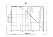
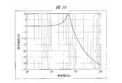
- FIG. 9 is a diagram showing an open circuit output characteristic with respect to an input angular velocity frequency of an angular velocity sensor having no detuning frequency (that is, a resonance frequency in the driving direction and a resonance frequency in the detection direction coincide with each other).
- FIG. 5 is a diagram having a detuning frequency of about 500 Hz.
- the output shows a flat signal strength characteristic up to a certain frequency, and after that, a characteristic that the gain decreases.
- the angular velocity sensor having the detuning frequency shown in FIG. 10 shows frequency characteristics having a peak in the detuning frequency band. This is because the sum of the frequency of the applied angular velocity and the frequency in the driving direction approaches the resonance frequency in the detection direction.
- the detection direction As a technique for eliminating the detuning frequency by making the resonance frequency in the drive direction and the resonance frequency in the detection direction the same, and applying a DC force to the mass in the detection direction, the detection direction Generally, a technique for changing the resonance frequency is known.
- the detuning frequency is individually adjusted for each sensor in order to adjust the detuning frequency, which varies from individual to individual. It was necessary to measure the frequency and set the value of the applied voltage. Therefore, there is a problem that a great adjustment cost is required for adjusting the detuning frequency that varies among the individual sensors. Furthermore, since it is necessary to maintain this throughout the period in which the sensor is used, there arises a problem that high cost is required for adjustment and performance maintenance of the sensor.
- the signal maximum value of the circuit is matched with the signal intensity at the time of detuning frequency generation to suppress the occurrence of saturation, the resolution in the band originally desired as a sensor, the so-called dynamic range deteriorates, The accuracy of the sensor may be reduced.
- the reliability and accuracy of the sensor are in a trade-off relationship.
- An object of the present invention is to provide a technique capable of ensuring the reliability and accuracy of a sensor while suppressing the adjustment cost of the sensor.
- the present invention includes a first detection element for detecting external acceleration, an acceleration signal processing unit for processing an acceleration signal detected by the first detection element, and a noise signal from a signal processed by the acceleration signal processing unit.
- a first filter for removing a physical quantity, a second detection element for detecting a physical quantity other than acceleration, a first physical quantity signal processing unit for processing a physical quantity signal detected by the second detection element, and the first A second filter that removes a noise signal from the signal processed by the physical quantity signal processing unit, a frequency component of the signal processed by the acceleration signal processing unit, and the frequency in the driving direction of the second detection element and the second It is determined whether a physical quantity having a detuning frequency component indicating a difference from the frequency in the detection direction of the detection element is applied, and the physical quantity having the detuning frequency component is applied.
- a signal component analysis unit that outputs an output stop signal when it is determined that the output signal is output from the first filter when an output stop signal is output from the signal component analysis unit. 1 output control unit, and a second output control unit that stops the output of the signal output from the second filter when the output stop signal is output from the signal component analysis unit.
- the first and second output control units output a signal flag indicating that the signal output is stopped when the output stop signal is output from the signal component analysis unit.
- the physical quantity detected by the second detection element is an angular velocity.
- the acceleration signal processing unit, the first and second filters, the signal component analysis unit, the first and second output control units, and the first physical quantity signal processing unit are one semiconductor chip. It is formed above.
- the present invention provides a third detection element that detects a physical quantity other than acceleration, a second physical quantity signal processing unit that processes a physical quantity signal detected by the third detection element, and the second physical quantity signal processing.
- a third filter that removes the noise signal from the signal processed by the unit, and a third output that stops the output of the signal output from the third filter when the output stop signal is output from the signal component analysis unit And a control unit.
- the present invention also provides a first semiconductor chip on which an acceleration signal processing unit, a first filter, a first output control unit, and a signal component analysis unit are formed, a first physical quantity signal processing unit, a second And a second semiconductor chip on which a second output control unit is formed.
- the first semiconductor chip is connected to the second semiconductor chip by a bonding wire and output from the signal component analysis unit The output stop signal is transmitted to the second output control unit via the bonding wire.
- the present invention includes a first detection element for detecting external acceleration, an acceleration signal processing unit for processing an acceleration signal detected by the first detection element, and a noise signal from a signal processed by the acceleration signal processing unit.
- a first filter for removing a physical quantity, a second detection element for detecting a physical quantity other than acceleration, a first physical quantity signal processing unit for processing a physical quantity signal detected by the second detection element, and the first A sensor module having a second filter that removes a noise signal from the signal processed by the physical quantity signal processing unit; and a processor that controls the actuator based on the signals output through the first and second filters;
- the processor includes a second filter for removing a noise signal from the signal processed by the first physical quantity signal processing unit, and an acceleration signal processing unit Whether or not a physical quantity having a detuning frequency component indicating the difference between the frequency in the driving direction of the second detection element and the frequency in the detection direction of the second detection element is applied by analyzing the frequency component of the signal And a signal component analyzer that outputs an output
- the present invention includes a first detection element for detecting acceleration from the outside, an acceleration signal processing unit for processing an acceleration signal detected by the first detection element, and a signal processed by the acceleration signal processing unit.
- a first filter that removes a noise signal
- a second detection element that detects a physical quantity other than acceleration
- a first physical quantity signal processing unit that processes a physical quantity signal detected by the second detection element
- a sensor module including a second filter for removing a noise signal from the signal processed by the physical quantity signal processing unit, and an actuator based on signals output through the first and second filters
- a processor, and the processor analyzes the frequency component of the signal output from the first filter, and determines the frequency in the driving direction of the second detection element and the first frequency.
- a signal component analysis unit that outputs a stop signal and an internal state determination unit that causes the processor to transition to a state in which the actuator is not controlled when the stop signal is output from the signal component analysis unit.
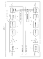
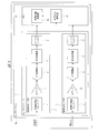
- FIG. 1 is a block diagram showing an example of the configuration of the sensor module according to Embodiment 1 of the present invention
- FIG. 2 is an explanatory diagram showing an example of the relationship between acceleration and other physical quantities
- FIG. 3 is the sensor of FIG.
- FIG. 4 is an explanatory diagram showing an example of a mounting form in a module
- FIG. 4 is an explanatory diagram showing another example of FIG. 3
- FIG. 5 is a block diagram showing another example of the sensor module of FIG.
- the first outline of the present invention includes a first detection element (acceleration detection element 4) for detecting acceleration from the outside, a second detection element (physical quantity detection element 11) for detecting a physical quantity other than acceleration,
- the acceleration signal processing unit (amplifier 5, A / D converter 6, signal processing unit 7) that processes the acceleration signal (voltage signal) detected by the first detection element, and noise from the signal processed by the acceleration signal processing unit
- the frequency component of the signal processed by the first filter (low-pass filter 8) for removing the signal and the acceleration signal processing unit is analyzed, and the frequency in the driving direction of the second detection element and the frequency of the second detection element are analyzed.
- a signal component analysis unit (signal component analysis unit 10) that outputs an output stop signal when the determination is made, and a signal output from the first filter when the output stop signal is output from the signal component analysis unit
- the sensor module includes a first physical quantity signal processing unit (amplifier 12, A / D converter 13, signal processing unit 14) that processes a physical quantity signal (voltage signal) detected by the second detection element; A second filter (low-pass filter 15) that removes a noise signal from the signal processed by the first physical quantity signal processing unit, and when the output stop signal is output from the signal component analysis unit, from the second filter A second output control unit (output signal control unit 16) for stopping the output of the output signal.
- a first physical quantity signal processing unit amplifier 12, A / D converter 13, signal processing unit 14
- a second filter low-pass filter 15
- the sensor module 1 is a module that detects various physical quantities, and is used, for example, in a skid prevention device mounted in an automobile or the like.
- the sensor module 1 includes an acceleration sensor unit 2 and a physical quantity sensor unit 3 as shown in FIG.
- the acceleration sensor unit 2 includes an acceleration detection element 4, an amplifier 5, an A / D (Analog / Digital) converter 6, a signal processing unit 7, a low-pass filter 8, an output signal control unit 9, and a signal component analysis unit 10. ing.
- the physical quantity sensor unit 3 includes a physical quantity detection element 11, an amplifier 12, an A / D converter 13, a signal processing unit 14, a low-pass filter 15, an output signal control unit 16, and a failure diagnosis unit 17.
- the signal component analysis unit 10 is provided in the acceleration sensor unit 2 and the failure diagnosis unit 17 is provided in the physical quantity sensor unit 3.
- the signal component analysis unit 10 and the failure diagnosis unit 17 include acceleration components.
- the structure provided in either the sensor part 2 or the physical quantity sensor part 3 may be sufficient.
- the acceleration detection element 4 detects acceleration from the outside.
- the amplifier 5 amplifies the signal detected by the acceleration detection element 4.
- the A / D converter 6 converts the analog signal output from the amplifier 5 into a digital signal.
- the signal processing unit 7 performs signal processing of the digital signal output from the A / D converter 6.
- the low-pass filter 8 is a filter that passes only low-frequency signals among the signals output from the signal processing unit 7.
- the output signal control unit 9 performs output control of the signal output from the low-pass filter 8 based on the output stop signal from the signal component analysis unit 10.
- the signal component analyzer 10 outputs an output stop signal to the output signal controllers 9 and 16 based on the analysis result analyzed by the signal processor 7.
- the physical quantity detection element 11 detects a physical quantity other than the acceleration from the outside.
- the amplifier 12 amplifies the signal detected by the physical quantity detection element 11.
- the A / D converter 13 converts the analog signal output from the amplifier 12 into a digital signal.
- the signal processing unit 14 performs signal processing of the digital signal output from the A / D converter 13.
- the low-pass filter 15 is a filter that passes only low-frequency signals among the signals output from the signal processing unit 14.
- the output signal control unit 16 performs output control of the signal output from the low-pass filter 15 based on the output stop signal from the signal component analysis unit 10.
- the failure diagnosis unit 17 notifies the output signal control units 9 and 16 of the failure.
- the acceleration detection element 4 is, for example, an electrostatic capacitance type element that captures a displacement of a mass mass generated by application of acceleration by a capacitance change, and converts the capacitance change into a voltage signal by C / V (Capacitance to Voltage) conversion. .
- the physical quantity detection element 11 detects a physical quantity other than acceleration from the outside, for example, an angular velocity. Similar to the acceleration detection element 4, the physical quantity detection element 11 is a capacitance-type element that captures the displacement of the mass generated by the application of the physical quantity as a change in capacitance. The change in capacitance is converted into a voltage signal by C / V conversion. Convert.
- an amplifier has an allowable signal level of an input signal (hereinafter referred to as “range”).
- range an allowable signal level of an input signal
- the signal range needs to be adjusted to a range not saturated by the signals from the acceleration detection element 4 and the physical quantity detection element 11. If the ranges of the amplifiers 5 and 12 are variable, the output range as a sensor is also variable, so the ranges of the amplifiers 5 and 12 may be variable.
- the voltage levels output from the amplifiers 5 and 12 are converted into digital values by the A / D converters 6 and 13, respectively.
- the subsequent signal processing units 7 and 14 can be digitized, and low-cost and high-accuracy signal processing can be realized.
- the A / D converters 6 and 13 may have any configuration, and so-called flash type, pipeline type, successive approximation type, and delta-sigma type are not limited.
- the digital signals that have passed through the A / D converters 6 and 13 are sent to the signal processing units 7 and 14, respectively, and are processed into appropriate signals as sensor output values by the signal processing units 7 and 14, respectively.
- demodulation is performed here. For example, when the carrier signal is superimposed, the signal processing units 7 and 14 perform synchronous detection and filtering of the carrier signal, and demodulate the baseband signal.
- output signal shaping such as compensation for temperature change, zero point correction, and sensitivity correction is performed.
- the above signal processing may be configured by a semiconductor integrated circuit device such as a dedicated LSI (Large Scale Integration), or may be composed of a DSP (Digital Signal Processor) and rewritable software corresponding thereto. .
- LSI Large Scale Integration
- DSP Digital Signal Processor
- the signal component analyzer 10 receives the signal output from the signal processor 7 and analyzes whether a physical quantity having a detuning frequency related to the physical quantity is applied.
- the detuning frequency is a frequency component indicating a difference between the frequency in the driving direction of the physical quantity detection element 11 and the frequency in the detection direction of the physical quantity detection element 11.
- the physical quantity detection element 11 When the physical quantity detection element 11 has a detuning frequency, the sum of the frequency of the applied angular velocity and the frequency in the driving direction approaches the resonance frequency in the detection direction, so that the sensor output has a peak in the detuning frequency band. It becomes frequency characteristic. Thereby, an abnormal value may be output from the sensor module 1.
- the signal component analysis unit 10 analyzes whether the resonance frequency is applied instead of the detuning frequency.
- the signal component analysis unit 10 preferably analyzes the baseband signal after signal demodulation by the signal processing unit 7 in order to determine the application of the detuning frequency, but the signal processing unit 7 does not perform any processing.
- the analysis may be performed from a signal that has not been performed, or the output from the A / D converter 6 may be directly analyzed without going through the signal processing unit 7 at all.
- an independent A / D converter (not shown) is provided for the signal component analysis unit 10 or a configuration in which an independent amplifier (not shown) is provided may be used. 10 may be given a signal.
- the signal processing unit 7 and the signal component analysis unit 10 do not have to be physically different circuits, and both may exist in a single semiconductor integrated circuit device such as an LSI. Further, the signal processing unit 7 and the signal component analysis unit 10 may be realized as DSP software.
- the signal component analysis unit 10 uses the digital signal of the acceleration detection element 4 to determine whether or not the detuning frequency component is included in a physical quantity other than acceleration by a certain value or more.
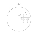
- FIG. 2 is an explanatory diagram illustrating an example of the relationship between acceleration and other physical quantities.
- the sensor module package 19 is mounted on the common substrate 18.
- the sensor module package 19 is a package on which the sensor module 1 is mounted.
- the common substrate 18 corresponds to, for example, a chassis in the case of an automobile.
- the acceleration sensor unit 2 is arranged on the left side of the sensor module package 19, and the physical quantity sensor unit 3 is arranged on the right side thereof.
- m is the mass of the acceleration detection mass of the acceleration sensor unit 2
- the acceleration sensor unit 2 and the physical quantity sensor unit 3 other than acceleration are configured to be housed in one sensor module package 19, but the acceleration sensor unit 2 and the physical quantity sensor unit 3 other than acceleration are in the same package. It is not always necessary to place it inside, and it is sufficient if it is on the common substrate 18.
- the common substrate 18 is not particularly limited as long as it is applied with the same physical quantity (in this case, the amount of inertia) such as a printed board or a casing.
- a Fourier analysis for calculating the frequency component is performed, and how much the component of the detuning frequency band is included is determined every discrete time T. It is possible to determine whether or not a certain threshold value is exceeded.
- analysis methods include wavelet analysis that can accurately analyze low-frequency bands even in a short time, and simple analysis methods that combine BPF (Band Pass Filter) and signal level determination. Any analysis method may be used as long as it can be determined that a physical quantity is applied.
- the signal component analysis unit 10 determines that the application of the detuning frequency component of the physical quantity exceeds a certain value, the signal component analysis unit 10 outputs an output stop signal to the output signal control units 9 and 16, respectively.
- the output signal control units 9 and 16 receive the output stop signal output from the signal component analysis unit 10, the acceleration signal from which noise is removed by the low-pass filters 8 and 15 through the signal processing units 7 and 14, and the physical quantity signal Stop the output of.
- the output signal control units 9 and 16 do not stop the signal output from the low-pass filters 8 and 15, but signal stop for notifying that the signal is temporarily stopped (hereinafter referred to as “suspend”). (For example, a continuous signal of “1”) may be output.
- the signal component analysis unit 10 determines that the application of the detuning frequency component of the physical quantity exceeds a certain value, the gain of the physical quantity detection element 11 or the amplifier 12 is decreased, or the A / D converter 6 If the approach is to maintain the function as a sensor even if accuracy degradation such as an increase in the range is allowed, or an angular velocity sensor that uses the Coriolis effect as a principle as shown in the background art, the amplitude in the driving direction is reduced (driving)
- the function maintenance described above can also be realized by reducing the voltage) and suppressing the occurrence of saturation. At this time, the outside may be notified that it is in an unsteady state.
- the failure diagnosis unit 17 is a circuit that monitors signals such as analog signals and digital signals in the sensor module 1 and notifies the output signal control units 9 and 16 of the failure when an abnormality is detected.
- the failure diagnosis unit 17 may be configured by a program or the like other than hardware.
- the failure diagnosis unit 17 When the signal component analysis unit 10 determines that the application of the detuning frequency component of the physical quantity exceeds a certain value, the failure diagnosis unit 17 notifies the determination result, and the failure diagnosis unit 17 notifies the internal signal value. It is also possible to instruct not to diagnose a sensor failure even if is an abnormal value.
- the configuration in which the output signal control units 9 and 16 are connected to the subsequent stage of the low-pass filters 8 and 15 is one example, and the place where the signal is stopped or the flag is added is anywhere in the circuit.
- it may be configured by a mechanism for indirectly stopping the signal, such as stopping the carrier signal applied to the physical quantity detection element 11 for a certain period of time.
- acceleration sensor and the angular velocity sensor is used in the detection principle of detuning frequency application, so when only acceleration is applied in the detuning frequency band, that is, when disturbance occurs, Suspend can occur.
- the physical quantity detection element 11 it is preferable to design the physical quantity detection element 11 so that the detuning frequency is wider than the necessary frequency band among the frequency components of the acceleration and is in a frequency band in which disturbance is unlikely to occur.
- the linearity of the output signal with respect to the displacement amount of the physical quantity detection element 11 is improved by configuring a servo circuit that suppresses the displacement of the physical quantity detection element 11, and the sensor module shown in FIG.
- a servo circuit in which a feedback path is added to the circuit configuration of 1 may be configured (not shown).
- the servo system needs to be configured such that its response frequency is higher than the detuning frequency band.
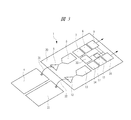
- FIG. 3 is an explanatory view showing an example of a mounting form in the sensor module 1.
- the sensor module 1 includes an amplifier 5, an A / D converter 6, a signal processing unit 7, a low-pass filter 8, an output signal control unit 9, a signal component analysis unit 10, an amplifier 12, and an A / D conversion.
- the acceleration detection element 4 and the physical quantity detection element 11 are connected to the semiconductor chip 20 on which the device 13, the signal processing unit 14, the low-pass filter 15, the output signal control unit 16, and the failure diagnosis unit 17 are formed.
- the acceleration detection element 4 is connected to the semiconductor chip 20 via a bonding wire 21, and the physical quantity detection element 11 is connected to the semiconductor chip 20 via a bonding wire 22.
- FIG. 4 is an explanatory diagram showing another example of FIG.
- the difference from FIG. 3 is that the semiconductor chip 23 on which the amplifier 5, the A / D converter 6, the signal processing unit 7, the low-pass filter 8, the output signal control unit 9, and the signal component analysis unit 10 are formed,
- the amplifier 12, the A / D converter 13, the signal processing unit 14, the low-pass filter 15, the output signal control unit 16, and the semiconductor chip 24 on which the failure diagnosis unit 17 is formed have a two-chip configuration.
- the acceleration detection element 4 is connected to the semiconductor chip 23 via a bonding wire 25, and the physical quantity detection element 11 is connected to the semiconductor chip 24 via a bonding wire 26.
- the bonding wire 27 is a signal line that transmits an output stop signal output from the signal component analysis unit 10 formed on the semiconductor chip 23 to the output signal control unit 16, and the bonding wire 28 is formed on the semiconductor chip 24. It is a signal line that transmits a signal notifying a failure output from the failure diagnosis unit 17.
- the output stop signal output from the signal component analysis unit 10 is input to the output signal control unit 9 formed on the semiconductor chip 23 and output signal control formed on the semiconductor chip 24 via the bonding wire 27. Input to the unit 16.
- a signal notifying the failure output from the failure diagnosis unit 17 is input to the output signal control unit 16 formed on the semiconductor chip 24 and also formed on the semiconductor chip 23 via the bonding wire 28. Input to the output signal control unit 9.
- the amplifier 5 the A / D converter 6, the signal processing unit 7, the low-pass filter 8, the output signal control unit 9, the signal component analysis unit 10, the amplifier 12, the A / D converter 13,
- the bonding wires 27 and 28 and the semiconductor chip are compared with the configuration shown in FIG. 4.
- the bonding electrodes necessary for bonding the bonding wires formed on 23 and 24 can be eliminated.
- the signal processing unit 7 can be shared to eliminate the need for the signal processing unit 14.
- the chip area can be reduced, and the sensor module can be reduced. 1 can be reduced in size and cost can be further reduced.
- the acceleration detection element 4 and the physical quantity detection element 11 are connected to the semiconductor chip 23 via the bonding wires 21 and 22.
- the acceleration detection element 4 and the physical quantity detection element 11 are connected to each other. You may make it form in the semiconductor chip 23. FIG. By adopting such a configuration, it is possible to reduce noise derived from parasitic components.
- FIG. 4 is not preferable from the viewpoint of cost, but is sufficient to implement the present embodiment, and it can be said that exercising this example by this mounting method is one of the options.
- the internal signals are processed digitally has been described.
- the internal signals may all be processed as analog.
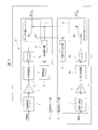
- the sensor module 1a includes an acceleration sensor unit 2a and a physical quantity sensor unit 3a as shown in FIG.
- the acceleration sensor unit 2a includes an acceleration detection element 4, an amplifier 5, a signal processing unit 7a, a low pass filter 8a, a band pass filter 29, an amplitude detector 30, and an output changeover switch 32.
- the physical quantity sensor unit 3a includes a physical quantity detection element 11, an amplifier 12, a signal processing unit 14a, a low-pass filter 15a, an interruption signal generation unit 31, and an output changeover switch 33.
- the amplitude detector 30 is provided in the acceleration sensor unit 2a and the interruption signal generation unit 31 is provided in the physical quantity sensor unit 3a.
- the amplitude detector 30 or the interruption signal generation unit 31a is What is necessary is just to be provided in either the acceleration sensor part 2a or the physical quantity sensor part 3a.
- the output part of the low-pass filter 8a is connected to one input part of the output changeover switch 32, and the output part of the interruption signal generation part 31 is connected to the other input part of the output changeover switch 32. .
- the output unit of the low-pass filter 15 a is connected to one input unit of the output changeover switch 33, and the output unit of the interruption signal generation unit 31 is connected to the other input unit of the output changeover switch 33. ing.
- the output changeover switch 32 switches and outputs either the signal output from the low-pass filter 8a or the signal output from the interruption signal generation unit 31 based on the determination result output from the amplitude detector 30.
- the output selector switch 33 switches and outputs either the signal output from the low-pass filter 15a or the signal output from the interruption signal generator 31 based on the determination result output from the amplitude detector 30.
- a band pass filter (BPF: Band Pass Filter) 29 and an amplitude detector are used to determine whether or not a signal in a detuned frequency band is applied.
- BPF Band Pass Filter
- the band-pass filter 29 passes only the signal in the detuned frequency band, and the amplitude detector 30 determines the square of the signal and the threshold value of the signal value, thereby separating the physical quantity other than the acceleration. It is possible to determine whether or not the adjustment frequency is applied.
- the output changeover switches 32 and 33 for selecting the signal from the interruption signal generation unit 31 indicating the interruption state and the signals from the low-pass filters 8a and 15a are set according to the signal output from the amplitude detector 30. To achieve suspend when the detuning frequency is applied.
- the signal output from the interruption signal generation unit 31 may be any signal that can be distinguished from the normal output, such as a ground (reference potential) level signal or a signal having a specific period, and the signal is particularly limited. is not.
- the output changeover switches 32 and 33 are not necessarily required, and the configuration may be such that the output of the amplitude detector 30 is output to the outside as it is, and the suspend is notified to the system side using the sensor through this.
- a physical quantity having a detuned frequency component peculiar to the physical quantity detection element 11 is applied from the signal frequency component of the broadband acceleration signal before passing through the low-pass filter 8. Therefore, the sensor output can be temporarily stopped and notified only when the application of the detuning frequency exceeds a certain level.
- the sensor module 1 was comprised from the acceleration sensor part 2 and the physical quantity sensor part 3 was described, it had two or more physical quantity sensor parts 3 except the failure diagnosis part 17. It is good also as a structure. Even in this case, the plurality of physical quantity sensor units 3 stops the output of the physical quantity signal based on the output stop signal output from the signal component analysis unit 10.
- FIG. 6 is an explanatory diagram showing an example of a sensor system configured using the sensor module according to Embodiment 2 of the present invention.
- the sensor system includes a processor (ECU 35) and a sensor module (sensor module 1).
- the sensor module includes a first detection element (acceleration detection element 4) that detects acceleration from the outside, and an acceleration signal processing unit (amplifier 5; amplifier 5) that processes an acceleration signal (voltage signal) detected by the first detection element.
- a detection element physical quantity detection element 11
- a first physical quantity signal processing unit amplifier 12, A / D converter 13, signal processing unit 14 for processing a physical quantity signal (voltage signal) detected by the second detection element.
- a second filter low-pass filter 15
- the processor performs an actuator control operation based on the signals output through the first and second filters, analyzes the frequency component of the signal processed by the acceleration signal processing unit, and It is determined whether a physical quantity having a detuning frequency component indicating a difference between a frequency in the driving direction of the second detection element and a frequency in the detection direction of the second detection element is applied, and the frequency component has the frequency component
- a signal component analysis unit (signal component analysis unit 10) that outputs an output stop signal when it is determined that a physical quantity is applied; and when the stop signal is output from the signal component analysis unit, the processor And an internal state determination unit (internal state determination unit 36) for transitioning to a state where the control operation is not performed.
- the sensor system 34 is, for example, a system used for an apparatus for preventing a side slip of an automobile.
- the sensor system 34 includes a sensor module 1 and an ECU (Electronic Control Unit) 35 as shown in FIG.
- the automobile is equipped with many ECUs that control various information systems such as navigation systems and audio systems, power train systems such as engines and chassis, and body systems such as air conditioners, headlights, and door locks. This is one of many semiconductor integrated circuit devices.
- the ECU 35 is connected to an actuator such as a hydraulic pump unit that operates the brake of the automobile, and controls the operation of the brake by controlling the actuator such as the hydraulic pump unit when the automobile slides. .
- the sensor module 1 shown in FIG. 6 includes an acceleration sensor unit 2 and a physical quantity sensor unit 3 as in FIG.
- the acceleration sensor unit 2 includes an acceleration detection element 4, an amplifier 5, an A / D converter 6, a signal processing unit 7, and a low-pass filter 8.
- a difference from the sensor module 1 in FIG. The point which provided the part 10 in ECU35 and the point which deleted the output signal control part 9 are the points.
- the physical quantity sensor unit 3 includes a physical quantity detection element 11, an amplifier 12, an A / D converter 13, a signal processing unit 14, and a low-pass filter 15.
- the difference from the sensor module 1 in FIG. 1 is an output signal control unit. 16 and the failure diagnosis unit 17 are deleted.
- the other configuration of the sensor module 1 of FIG. 6 is the same as that of FIG.
- the ECU 35 has a signal other than the signal output from the acceleration sensor unit 2 (acceleration signal output through the low-pass filter 8) and the signal output from the physical quantity sensor unit 3 (acceleration output through the low-pass filter 15). (Physical quantity signals) are input so that the ECU 35 controls the skid prevention based on these signals.
- the ECU 35 is provided with the signal component analysis unit 10 as described above, and further includes an internal state determination unit 36.
- the signal component analyzer 10 is connected so that the signal output from the signal processor 7 (the signal before being input to the low-pass filter 8) is input.
- the internal state determination unit 36 changes the internal state switching according to the analysis result of the signal component analysis unit 10, and corresponds to the output signal control units 9 and 16 in FIG.
- the signal component analysis unit 10 and the internal state determination unit 36 are configured by a DSP provided in the ECU 35 and software corresponding thereto.
- the switching of the internal state is, for example, a first state where a signal output from the sensor module 1 can be used (that is, a state where the output value is reliable) and a signal output from the sensor module 1 are not used. Refers to a possible mutual transition of the second state.
- the internal state determination unit 36 performs brake control using the sensor output value, and when in the second state, the internal state determination unit 36 does not perform any brake control. Thus, the reliability and safety of the sensor system 34 can be ensured.
- condition for determining the state transition of the internal state determination unit 36 may be dynamically changed, or may be recorded in a memory that cannot be changed in advance. Moreover, you may provide the display part which displays an internal state.
- the highly reliable sensor module 1 can be realized.
- the sensor system 34 can be dealt with only by changing the software of the ECU 35 without making the sensor system 34 complicated, an increase in the cost of the entire sensor system 34 can be suppressed.
- the sensor system 34 is suitable because the physical quantity detected by the physical quantity detection element 11 is an angular velocity and is strongly related to the signal as shown in the first embodiment. However, it may be a different physical quantity such as pressure.
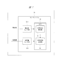
- FIG. 7 is an explanatory diagram showing an example of a sensor system configured using the sensor module according to the third embodiment of the present invention.
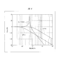
- FIG. 8 shows the sensor response and the characteristics of the low-pass filter in the acceleration sensor unit shown in FIG. It is explanatory drawing which showed this relationship.
- the sensor system includes a processor and a sensor module.
- the sensor module includes a first detection element (acceleration detection element 4) that detects acceleration from the outside, and an acceleration signal processing unit (amplifier 5; amplifier 5) that processes an acceleration signal (voltage signal) detected by the first detection element.
- a detection element physical quantity detection element 11
- a first physical quantity signal processing unit amplifier 12, A / D converter 13, signal processing unit 14 for processing a physical quantity signal (voltage signal) detected by the second detection element.
- a second filter low-pass filter 15
- the processor controls the actuator based on the signals output through the first and second filters, analyzes the frequency component of the signal output from the first filter, and It is determined whether a physical quantity having a detuning frequency component indicating a difference between a frequency in the driving direction of the second detection element and a frequency in the detection direction of the second detection element is applied, and the physical quantity having the frequency component
- a signal component analysis unit (signal component analysis unit 10) that outputs an output stop signal when it is determined that the signal is applied, and when the stop signal is output from the signal component analysis unit, the processor
- An internal state determination unit (internal state determination unit 36) that makes a transition to a state in which control is not performed.
- the sensor system 34 has the same configuration as the sensor module 1 including the acceleration sensor unit 2 and the physical quantity sensor unit 3 and the sensor system 34 illustrated in FIG. 6 including the ECU 35.
- the ECU 35 is provided with a signal component analysis unit 10 and an internal state determination unit 36 as in FIG. 6 of the second embodiment.
- the sensor module 1 includes an acceleration sensor unit 2 and a physical quantity sensor unit 3.
- the sensor system 34 shown in FIG. 7 is different from the sensor system 34 shown in FIG. A connection line to which the signal component analysis unit 10 is connected is deleted.
- FIG. 8 is an explanatory diagram showing the relationship between the sensor response in the acceleration sensor unit 2 shown in FIG. 7 and the characteristics of the low-pass filter 8.
- the detuning frequency of the physical quantity sensor unit 3 is about 500 Hz
- a sensor response (frequency characteristic) having a peak at 500 Hz is obtained as shown in FIG.
- the cut-off of the low-pass filter 8 in the acceleration sensor unit 2 is lower than the detuning frequency, that is, when it has the characteristics indicated by LPF-A in the figure, as described in the first and second embodiments. Therefore, it is necessary to determine whether to apply the detuning frequency using a signal preceding the low-pass filter 8, that is, a signal output from the signal processing unit 7.
- the cutoff of the output characteristic of the low-pass filter 8 in the acceleration sensor unit 2 is higher than the detuning frequency, that is, when it has the characteristic of LPF-B in the figure, the signal before being input to the low-pass filter 8 is signaled. It is not necessary to have a configuration for inputting to the component analysis unit 10.
- the sensor system 34 is configured to input the output of the acceleration sensor unit 2 to the signal component analysis unit 10, and is similar to the signal component analysis unit 10 shown in FIG. 1 of the first embodiment.
- the internal state determination unit 36 can determine whether or not the detuning frequency is applied.
- the signal is strongly related as shown in the first embodiment, which is preferable. However, it may be a different physical quantity such as pressure.
- the present invention is suitable for a technique for preventing an abnormal output value by detecting an angular velocity in the vicinity of a detuning frequency in a sensor that detects acceleration from the outside and a physical quantity other than acceleration from the outside.
Landscapes
- Engineering & Computer Science (AREA)
- Radar, Positioning & Navigation (AREA)
- Remote Sensing (AREA)
- Physics & Mathematics (AREA)
- General Physics & Mathematics (AREA)
- Automation & Control Theory (AREA)
- Signal Processing (AREA)
- Gyroscopes (AREA)
- Pressure Sensors (AREA)
Abstract
Description
図1は、本発明の実施の形態1によるセンサモジュールにおける構成の一例を示すブロック図、図2は、加速度と他の物理量の関連性の一例を示す説明図、図3は、図1のセンサモジュールにおける実装形態の一例を示した説明図、図4は、図3の他の例を示す説明図、図5は、図1のセンサモジュールにおける他の例を示すブロック図である。
本発明の第1の概要は、外部からの加速度を検出する第1の検出エレメント(加速度検出エレメント4)と、加速度以外の物理量を検出する第2の検出エレメント(物理量検出エレメント11)と、前記第1の検出エレメントが検出した加速度信号(電圧信号)を処理する加速度信号処理部(アンプ5、A/D変換器6、信号処理部7)と、前記加速度信号処理部が処理した信号からノイズ信号を除去する第1のフィルタ(ローパスフィルタ8)と、前記加速度信号処理部が処理した信号の周波数成分を解析し、前記第2の検出エレメントの駆動方向の周波数と前記第2の検出エレメントの検出方向の周波数との差を示す離調周波数成分を有する物理量が印加されているか否かを判定し、前記離調周波数成分を有する物理量が印加されていると判定した際に出力停止信号を出力する信号成分解析部(信号成分解析部10)と、前記信号成分解析部から出力停止信号が出力された際に、前記第1のフィルタから出力される信号の出力を停止する第1の出力制御部(出力信号制御部9)とを有するセンサモジュールである。
図6は、本発明の実施の形態2によるセンサモジュールを用いて構成されたセンサシステムにおける一例を示す説明図である。
本発明の第2の概要は、センサシステム(センサシステム34)が、プロセッサ(ECU35)、およびセンサモジュール(センサモジュール1)から構成されている。
図7は、本発明の実施の形態3によるセンサモジュールを用いて構成されたセンサシステムにおける一例を示す説明図、図8は、図7に示した加速度センサ部におけるセンサ応答とローパスフィルタの特性との関係を示した説明図である。
本発明の第3の概要は、センサシステムが、プロセッサと、センサモジュールとから構成されている。
1a センサモジュール
2 加速度センサ部
2a 加速度センサ部
3 物理量センサ部
3a 物理量センサ部
4 加速度検出エレメント
5 アンプ
6 A/D変換器
7 信号処理部
7a 信号処理部
8 ローパスフィルタ
8a ローパスフィルタ
9 出力信号制御部
10 信号成分解析部
11 物理量検出エレメント
12 アンプ
13 A/D変換器
14 信号処理部
14a 信号処理部
15 ローパスフィルタ
15a ローパスフィルタ
16 出力信号制御部
17 故障診断部
18 共通基板
19 センサモジュールパッケージ
20 半導体チップ
21 ボンディングワイヤ
22 ボンディングワイヤ
23 半導体チップ
24 半導体チップ
25 ボンディングワイヤ
26 ボンディングワイヤ
27 ボンディングワイヤ
28 ボンディングワイヤ
29 帯域通過フィルタ
30 振幅検出器
31 中断信号生成部
32 出力切り替えスイッチ
33 出力切り替えスイッチ
34 センサシステム
35 ECU
36 内部状態決定部
Claims (16)
- 外部からの加速度を検出する第1の検出エレメントと、
前記第1の検出エレメントが検出した加速度信号を処理する加速度信号処理部と、
前記加速度信号処理部が処理した信号からノイズ信号を除去する第1のフィルタと、
加速度以外の物理量を検出する第2の検出エレメントと、
前記第2の検出エレメントが検出した物理量信号を処理する第1の物理量信号処理部と、
前記第1の物理量信号処理部が処理した信号からノイズ信号を除去する第2のフィルタと、
前記加速度信号処理部が処理した信号の周波数成分を解析し、前記第2の検出エレメントの駆動方向の周波数と前記第2の検出エレメントの検出方向の周波数との差を示す離調周波数成分を有する物理量が印加されているか否かを判定し、前記離調周波数成分を有する物理量が印加されていると判定した際に出力停止信号を出力する信号成分解析部と、
前記信号成分解析部から出力停止信号が出力された際に、前記第1のフィルタから出力される信号の出力を停止する第1の出力制御部と、
前記信号成分解析部から出力停止信号が出力された際に、前記第2のフィルタから出力される信号の出力を停止する第2の出力制御部とを有することを特徴とするセンサモジュール。 - 請求項1記載のセンサモジュールにおいて、
前記第1、および前記第2の出力制御部は、前記信号成分解析部から出力停止信号が出力された際に、信号出力が停止したことを示す信号フラグを出力することを特徴とするセンサモジュール。 - 請求項1記載のセンサモジュールにおいて、
前記第2の検出エレメントが検出する物理量が角速度であることを特徴とするセンサモジュール。 - 請求項1記載のセンサモジュールにおいて、
前記加速度信号処理部、前記第1、および前記第2のフィルタ、前記信号成分解析部、前記第1、および前記第2の出力制御部、および前記第1の物理量信号処理部が、1つの半導体チップ上に形成されていることを特徴とするセンサモジュール。 - 請求項1記載のセンサモジュールにおいて、
加速度以外の物理量を検出する第3の検出エレメントと、
前記第3の検出エレメントが検出した物理量信号を処理する第2の物理量信号処理部と、
前記第2の物理量信号処理部が処理した信号からノイズ信号を除去する第3のフィルタと、
前記信号成分解析部から出力停止信号が出力された際に、前記第3のフィルタから出力される信号の出力を停止する第3の出力制御部とをさらに有することを特徴とするセンサモジュール。 - 請求項5記載のセンサモジュールにおいて、
前記第2の検出エレメントが検出する物理量が角速度であることを特徴とするセンサモジュール。 - 請求項1記載のセンサモジュールにおいて、
前記加速度信号処理部、前記第1のフィルタ、前記第1の出力制御部、および前記信号成分解析部が形成された第1の半導体チップと、
前記第1の物理量信号処理部、前記第2のフィルタ、および前記第2の出力制御部が形成された第2の半導体チップとを有し、
前記第1の半導体チップは、
前記第2の半導体チップとボンディングワイヤによって接続され、前記信号成分解析部から出力された出力停止信号を前記ボンディングワイヤを介して前記第2の出力制御部に伝達することを特徴とするセンサモジュール。 - 請求項1記載のセンサモジュールにおいて、
前記加速度信号処理部、前記第1のフィルタ、および前記第1の出力制御部が形成された第1の半導体チップと、
前記第1の物理量信号処理部、前記第2のフィルタ、前記第2の出力制御部、および前記信号成分解析部が形成された第2の半導体チップとを有し、
前記第2の半導体チップは、
前記第1の半導体チップとボンディングワイヤによって接続されており、前記信号成分解析部から出力される出力停止信号を前記ボンディングワイヤを介して前記第1の出力制御部に伝達することを特徴とするセンサモジュール。 - 外部からの加速度を検出する第1の検出エレメントと、前記第1の検出エレメントが検出した加速度信号を処理する加速度信号処理部と、前記加速度信号処理部が処理した信号からノイズ信号を除去する第1のフィルタと、加速度以外の物理量を検出する第2の検出エレメントと、前記第2の検出エレメントが検出した物理量信号を処理する第1の物理量信号処理部と、前記第1の物理量信号処理部が処理した信号からノイズ信号を除去する第2のフィルタとを有するセンサモジュールと、
前記第1、および前記第2のフィルタを介して出力された信号に基づいて、アクチュエータを制御するプロセッサとを有し、
前記プロセッサは、
前記第1の物理量信号処理部が処理した信号からノイズ信号を除去する第2のフィルタと、
前記加速度信号処理部が処理した信号の周波数成分を解析し、前記第2の検出エレメントの駆動方向の周波数と前記第2の検出エレメントの検出方向の周波数との差を示す離調周波数成分を有する物理量が印加されているか否かを判定し、前記離調周波数成分を有する物理量が印加されていると判定した際に出力停止信号を出力する信号成分解析部と、
前記信号成分解析部から停止信号が出力された際に、前記プロセッサが前記アクチュエータの制御を行わない状態に遷移させる内部状態決定部とを有することを特徴とするセンサシステム。 - 請求項9記載のセンサシステムにおいて、
前記第2の検出エレメントが検出する物理量が角速度であることを特徴とするセンサシステム。 - 請求項9記載のセンサシステムにおいて、
前記センサモジュールは、
加速度以外の物理量を検出する第3の検出エレメントと、
前記第3の検出エレメントが検出した物理量信号を処理する第2の物理量信号処理部と、
前記第2の物理量信号処理部が処理した信号からノイズ信号を除去する第3のフィルタと、
前記信号成分解析部から出力停止信号が出力された際に、前記第3のフィルタから出力される信号の出力を停止する第3の出力制御部とをさらに有することを特徴とするセンサシステム。 - 請求項11記載のセンサシステムにおいて、
前記第2の検出エレメントが検出する物理量が角速度であることを特徴とするセンサシステム。 - 外部からの加速度を検出する第1の検出エレメントと、前記第1の検出エレメントが検出した加速度信号を処理する加速度信号処理部と、前記加速度信号処理部が処理した信号からノイズ信号を除去する第1のフィルタと、加速度以外の物理量を検出する第2の検出エレメントと、前記第2の検出エレメントが検出した物理量信号を処理する第1の物理量信号処理部と、前記第1の物理量信号処理部が処理した信号からノイズ信号を除去する第2のフィルタとを備えたセンサモジュールと、
前記第1、および前記第2のフィルタを介して出力された信号に基づいて、アクチュエータを制御するプロセッサとを有し、
前記プロセッサは、
前記第1のフィルタから出力された信号の周波数成分を解析し、前記第2の検出エレメントの駆動方向の周波数と前記第2の検出エレメントの検出方向の周波数との差を示す離調周波数成分を有する物理量が印加されているか否かを判定し、前記離調周波数成分を有する物理量が印加されていると判定した際に出力停止信号を出力する信号成分解析部と、
前記信号成分解析部から停止信号が出力された際に、前記プロセッサが前記アクチュエータの制御を行わない状態に遷移させる内部状態決定部とを有することを特徴とするセンサシステム。 - 請求項13記載のセンサシステムにおいて、
前記第2の検出エレメントが検出する物理量が角速度であることを特徴とするセンサシステム。 - 請求項13記載のセンサシステムにおいて、
前記センサモジュールは、
加速度以外の物理量を検出する第3の検出エレメントと、
前記第3の検出エレメントが検出した物理量信号を処理する第2の物理量信号処理部と、
前記第2の物理量信号処理部が処理した信号からノイズ信号を除去する第3のフィルタと、
前記信号成分解析部から出力停止信号が出力された際に、前記第3のフィルタから出力される信号の出力を停止する第3の出力制御部とをさらに有することを特徴とするセンサシステム。 - 請求項15記載のセンサシステムにおいて、
前記第2の検出エレメントが検出する物理量が角速度であることを特徴とするセンサシステム。
Priority Applications (2)
| Application Number | Priority Date | Filing Date | Title |
|---|---|---|---|
| US13/976,372 US9279827B2 (en) | 2010-12-27 | 2011-11-24 | Sensor module and sensor system |
| DE112011104604.9T DE112011104604T5 (de) | 2010-12-27 | 2011-11-24 | Sensormodul und Sensorsytem |
Applications Claiming Priority (2)
| Application Number | Priority Date | Filing Date | Title |
|---|---|---|---|
| JP2010-291015 | 2010-12-27 | ||
| JP2010291015A JP5512507B2 (ja) | 2010-12-27 | 2010-12-27 | センサモジュール、およびセンサシステム |
Publications (1)
| Publication Number | Publication Date |
|---|---|
| WO2012090627A1 true WO2012090627A1 (ja) | 2012-07-05 |
Family
ID=46382747
Family Applications (1)
| Application Number | Title | Priority Date | Filing Date |
|---|---|---|---|
| PCT/JP2011/077070 Ceased WO2012090627A1 (ja) | 2010-12-27 | 2011-11-24 | センサモジュール、およびセンサシステム |
Country Status (4)
| Country | Link |
|---|---|
| US (1) | US9279827B2 (ja) |
| JP (1) | JP5512507B2 (ja) |
| DE (1) | DE112011104604T5 (ja) |
| WO (1) | WO2012090627A1 (ja) |
Cited By (1)
| Publication number | Priority date | Publication date | Assignee | Title |
|---|---|---|---|---|
| CN104535798A (zh) * | 2014-12-29 | 2015-04-22 | 苏州中盛纳米科技有限公司 | 一种批量加速度传感器翻滚平台的控制系统及控制方法 |
Families Citing this family (8)
| Publication number | Priority date | Publication date | Assignee | Title |
|---|---|---|---|---|
| JP6194606B2 (ja) * | 2013-03-22 | 2017-09-13 | セイコーエプソン株式会社 | 検出装置、センサー、ジャイロセンサー、電子機器及び移動体 |
| JP2016197049A (ja) * | 2015-04-03 | 2016-11-24 | 株式会社デンソー | 角速度検出装置 |
| CN107636438B (zh) * | 2016-11-04 | 2020-04-17 | 歌尔股份有限公司 | 信号处理装置、气压传感器组件和电子设备 |
| JP6780595B2 (ja) * | 2017-07-18 | 2020-11-04 | 横河電機株式会社 | 機器情報提供装置、機器情報提供方法、機器情報提供プログラム及び記録媒体 |
| DE102017222656A1 (de) * | 2017-12-13 | 2019-06-13 | Bayerische Motoren Werke Aktiengesellschaft | Sensor und sensorsystem |
| DE102020213286A1 (de) * | 2020-10-21 | 2022-04-21 | Robert Bosch Gesellschaft mit beschränkter Haftung | Verfahren zur Bestimmung einer Phasenlage eines Drehratensignals oder eines Quadratursignals, Verfahren zur Anpassung einer Demodulationsphase und Drehratensensor |
| CN112377153B (zh) * | 2020-10-29 | 2021-11-30 | 中国科学院沈阳自动化研究所 | 一种基于加速度传感器获取游梁抽油机冲程和冲次的方法 |
| JP7791906B2 (ja) * | 2021-12-23 | 2025-12-24 | ロベルト・ボッシュ・ゲゼルシャフト・ミト・ベシュレンクテル・ハフツング | 処理装置、センサ装置、制御システムおよび処理方法 |
Citations (4)
| Publication number | Priority date | Publication date | Assignee | Title |
|---|---|---|---|---|
| JPS61191171A (ja) * | 1985-02-19 | 1986-08-25 | Matsushita Electric Ind Co Ltd | 撮影装置 |
| JP2005241359A (ja) * | 2004-02-25 | 2005-09-08 | Denso Corp | 車両横転検知用振動型角速度センサ |
| JP2007187606A (ja) * | 2006-01-16 | 2007-07-26 | Japan Aviation Electronics Industry Ltd | 振動ジャイロ |
| JP2007532932A (ja) * | 2004-04-16 | 2007-11-15 | ヴアブコ・ゲゼルシヤフト・ミツト・ベシユレンクテル・ハフツング・ウント・コンパニー・オツフエネハンデルスゲゼルシヤフト | センサの操作方法 |
Family Cites Families (5)
| Publication number | Priority date | Publication date | Assignee | Title |
|---|---|---|---|---|
| JP4392599B2 (ja) | 2004-03-25 | 2010-01-06 | 株式会社デンソー | センサシステム |
| JP2005283481A (ja) | 2004-03-30 | 2005-10-13 | Denso Corp | センサシステム |
| JP4449074B2 (ja) | 2004-03-30 | 2010-04-14 | 株式会社デンソー | センサシステム |
| JP5286725B2 (ja) | 2007-03-09 | 2013-09-11 | パナソニック株式会社 | 角速度センサ |
| DE102007011816B4 (de) | 2007-03-12 | 2013-10-02 | Infineon Technologies Ag | Sensor und Verfahren zum Erfassen einer Linearbeschleunigung und einer Winkelgeschwindigkeit |
-
2010
- 2010-12-27 JP JP2010291015A patent/JP5512507B2/ja not_active Expired - Fee Related
-
2011
- 2011-11-24 WO PCT/JP2011/077070 patent/WO2012090627A1/ja not_active Ceased
- 2011-11-24 US US13/976,372 patent/US9279827B2/en not_active Expired - Fee Related
- 2011-11-24 DE DE112011104604.9T patent/DE112011104604T5/de not_active Withdrawn
Patent Citations (4)
| Publication number | Priority date | Publication date | Assignee | Title |
|---|---|---|---|---|
| JPS61191171A (ja) * | 1985-02-19 | 1986-08-25 | Matsushita Electric Ind Co Ltd | 撮影装置 |
| JP2005241359A (ja) * | 2004-02-25 | 2005-09-08 | Denso Corp | 車両横転検知用振動型角速度センサ |
| JP2007532932A (ja) * | 2004-04-16 | 2007-11-15 | ヴアブコ・ゲゼルシヤフト・ミツト・ベシユレンクテル・ハフツング・ウント・コンパニー・オツフエネハンデルスゲゼルシヤフト | センサの操作方法 |
| JP2007187606A (ja) * | 2006-01-16 | 2007-07-26 | Japan Aviation Electronics Industry Ltd | 振動ジャイロ |
Cited By (1)
| Publication number | Priority date | Publication date | Assignee | Title |
|---|---|---|---|---|
| CN104535798A (zh) * | 2014-12-29 | 2015-04-22 | 苏州中盛纳米科技有限公司 | 一种批量加速度传感器翻滚平台的控制系统及控制方法 |
Also Published As
| Publication number | Publication date |
|---|---|
| US9279827B2 (en) | 2016-03-08 |
| DE112011104604T5 (de) | 2014-01-09 |
| US20130319075A1 (en) | 2013-12-05 |
| JP5512507B2 (ja) | 2014-06-04 |
| JP2012137426A (ja) | 2012-07-19 |
Similar Documents
| Publication | Publication Date | Title |
|---|---|---|
| JP5512507B2 (ja) | センサモジュール、およびセンサシステム | |
| CN102341712B (zh) | 用于在车辆移动时自动校准安装在所述车辆的轮子上的加速度传感器的方法 | |
| US7281522B1 (en) | Acceleration sensor status detecting apparatus | |
| US20120176070A1 (en) | Method for analyzing signals from an angle sensor | |
| US7284408B2 (en) | Sensor system | |
| US10119985B2 (en) | Multi-function speed sensor | |
| JP5444875B2 (ja) | ロボット制御装置 | |
| JP4645768B1 (ja) | 電子機器 | |
| US7233847B2 (en) | Sensor system | |
| JP6660295B2 (ja) | ピックオフトランスデューサワイヤボンドビット検出 | |
| JP6338738B1 (ja) | 回転角センサ情報の異常診断装置 | |
| US8573055B2 (en) | Angular velocity sensor | |
| JP2020024166A (ja) | 異常状態判定システム | |
| US7305863B2 (en) | Impact sensor and method for testing the same | |
| JP2003525814A (ja) | 冗長的な測定チャンネルによってヨーイング運動を検出するシステムと装置 | |
| JP2013137275A (ja) | センサ動作検出装置、センサ動作検出システム及びセンサ動作検出方法 | |
| WO2022239692A1 (ja) | 加速度センサ | |
| JP2011033385A (ja) | コリオリ質量流量計 | |
| KR101030602B1 (ko) | 전자기기 | |
| US20220357357A1 (en) | Micromechanical inertial sensor | |
| JP6848222B2 (ja) | 速度センサインタフェース回路 | |
| JPH11237238A (ja) | 回転体軸偏心量測定装置 | |
| JP5429575B2 (ja) | レゾルバ信号処理装置 | |
| KR100721384B1 (ko) | 차속신호 처리장치 | |
| JP2025023466A (ja) | 回路装置および物理量センサー |
Legal Events
| Date | Code | Title | Description |
|---|---|---|---|
| 121 | Ep: the epo has been informed by wipo that ep was designated in this application |
Ref document number: 11853510 Country of ref document: EP Kind code of ref document: A1 |
|
| WWE | Wipo information: entry into national phase |
Ref document number: 1120111046049 Country of ref document: DE Ref document number: 112011104604 Country of ref document: DE |
|
| WWE | Wipo information: entry into national phase |
Ref document number: 13976372 Country of ref document: US |
|
| 122 | Ep: pct application non-entry in european phase |
Ref document number: 11853510 Country of ref document: EP Kind code of ref document: A1 |