WO2012090301A1 - 入出金装置、補充回収装置及び、入出金装置の運用方法 - Google Patents
入出金装置、補充回収装置及び、入出金装置の運用方法 Download PDFInfo
- Publication number
- WO2012090301A1 WO2012090301A1 PCT/JP2010/073725 JP2010073725W WO2012090301A1 WO 2012090301 A1 WO2012090301 A1 WO 2012090301A1 JP 2010073725 W JP2010073725 W JP 2010073725W WO 2012090301 A1 WO2012090301 A1 WO 2012090301A1
- Authority
- WO
- WIPO (PCT)
- Prior art keywords
- unit
- banknote
- banknotes
- storage unit
- deposit
- Prior art date
- Legal status (The legal status is an assumption and is not a legal conclusion. Google has not performed a legal analysis and makes no representation as to the accuracy of the status listed.)
- Ceased
Links
Images




Classifications
-
- G—PHYSICS
- G07—CHECKING-DEVICES
- G07F—COIN-FREED OR LIKE APPARATUS
- G07F19/00—Complete banking systems; Coded card-freed arrangements adapted for dispensing or receiving monies or the like and posting such transactions to existing accounts, e.g. automatic teller machines
- G07F19/20—Automatic teller machines [ATMs]
- G07F19/202—Depositing operations within ATMs
-
- B—PERFORMING OPERATIONS; TRANSPORTING
- B65—CONVEYING; PACKING; STORING; HANDLING THIN OR FILAMENTARY MATERIAL
- B65H—HANDLING THIN OR FILAMENTARY MATERIAL, e.g. SHEETS, WEBS, CABLES
- B65H29/00—Delivering or advancing articles from machines; Advancing articles to or into piles
- B65H29/006—Winding articles into rolls
-
- G—PHYSICS
- G07—CHECKING-DEVICES
- G07D—HANDLING OF COINS OR VALUABLE PAPERS, e.g. TESTING, SORTING BY DENOMINATIONS, COUNTING, DISPENSING, CHANGING OR DEPOSITING
- G07D11/00—Devices accepting coins; Devices accepting, dispensing, sorting or counting valuable papers
- G07D11/20—Controlling or monitoring the operation of devices; Data handling
- G07D11/24—Managing the inventory of valuable papers
- G07D11/245—Replenishment
-
- G—PHYSICS
- G07—CHECKING-DEVICES
- G07D—HANDLING OF COINS OR VALUABLE PAPERS, e.g. TESTING, SORTING BY DENOMINATIONS, COUNTING, DISPENSING, CHANGING OR DEPOSITING
- G07D11/00—Devices accepting coins; Devices accepting, dispensing, sorting or counting valuable papers
- G07D11/20—Controlling or monitoring the operation of devices; Data handling
- G07D11/32—Record keeping
- G07D11/34—Monitoring the contents of devices, e.g. the number of stored valuable papers
-
- G—PHYSICS
- G07—CHECKING-DEVICES
- G07D—HANDLING OF COINS OR VALUABLE PAPERS, e.g. TESTING, SORTING BY DENOMINATIONS, COUNTING, DISPENSING, CHANGING OR DEPOSITING
- G07D11/00—Devices accepting coins; Devices accepting, dispensing, sorting or counting valuable papers
- G07D11/50—Sorting or counting valuable papers
-
- B—PERFORMING OPERATIONS; TRANSPORTING
- B65—CONVEYING; PACKING; STORING; HANDLING THIN OR FILAMENTARY MATERIAL
- B65H—HANDLING THIN OR FILAMENTARY MATERIAL, e.g. SHEETS, WEBS, CABLES
- B65H2301/00—Handling processes for sheets or webs
- B65H2301/40—Type of handling process
- B65H2301/41—Winding, unwinding
- B65H2301/419—Winding, unwinding from or to storage, i.e. the storage integrating winding or unwinding means
- B65H2301/4191—Winding, unwinding from or to storage, i.e. the storage integrating winding or unwinding means for handling articles of limited length, e.g. AO format, arranged at intervals from each other
- B65H2301/41912—Winding, unwinding from or to storage, i.e. the storage integrating winding or unwinding means for handling articles of limited length, e.g. AO format, arranged at intervals from each other between two belt like members
-
- B—PERFORMING OPERATIONS; TRANSPORTING
- B65—CONVEYING; PACKING; STORING; HANDLING THIN OR FILAMENTARY MATERIAL
- B65H—HANDLING THIN OR FILAMENTARY MATERIAL, e.g. SHEETS, WEBS, CABLES
- B65H2701/00—Handled material; Storage means
- B65H2701/10—Handled articles or webs
- B65H2701/19—Specific article or web
- B65H2701/1912—Banknotes, bills and cheques or the like
Definitions
- the present invention relates to a deposit / withdrawal device, a replenishment / collection device, and an operation method of the deposit / withdrawal device.
- a drum that can be rotated in the forward and reverse directions is provided in a storage unit that stores banknotes of a plurality of denominations by winding a banknote between two tapes (for example, a patent). Reference 3).
- Patent Document 1 when banknotes used as change are stacked and stored in a stacked state, a conveyance failure such as a double feed may occur at the time of feeding. Moreover, an error may occur in the management of the number of banknotes due to the double feed. Therefore, it is necessary to provide a feeding mechanism by managing friction or a gap in the bill feeding part of the bill storage part. For this purpose, it is necessary to use dedicated storage units and feeding units that are individually adjusted according to the size of each bill, and when changing the bills handled, mechanical adjustment is indispensable. It is inconvenient that it cannot be used for different banknotes.
- An object of the present invention is to provide a deposit / withdrawal device, a replenishment / collection device, and an operation method of the deposit / withdrawal device that can efficiently replenish or collect bills with the same configuration regardless of the size of the bills.
- a deposit / withdrawal apparatus that is one aspect of the present invention is a deposit / withdrawal apparatus that deposits and withdraws banknotes, and can store banknotes of one or more denominations, and includes denominations of banknotes stored.
- a detachable banknote storage section for storing and discharging banknotes; a mounting section for mounting the banknote storage section; and the mounting section for mounting the banknote storage section.
- a detection unit that detects whether the banknote storage unit is mounted, a reading unit that reads the denomination of the banknote from the first storage unit, the mounting unit, and the mounting
- a second storage unit that stores the denomination of the banknote stored in the banknote storage unit attached to the storage unit in association with the denomination of the banknote read by the reading unit is the second storage.
- a storage unit discriminating unit that discriminates whether or not the stored denomination matches, and an instruction reception that starts accepting an instruction for depositing or withdrawing the banknote when it is determined that the storage discriminating unit is suitable
- a transport unit that transports the banknote based on the instruction.
- Another embodiment of the deposit / withdrawal device is capable of storing banknotes of one or more denominations, has a first storage unit having storage information including denominations of banknotes stored therein, and stores banknotes And a detachable banknote storage unit to be discharged, a mounting unit for mounting the banknote storage unit, a detection unit for detecting whether the banknote storage unit is mounted on the mounting unit, and the detection unit for the banknote
- a reading unit that reads the denomination from the first storage unit
- a second storage unit that stores the denomination read by the reading unit in association with the mounting unit
- an instruction receiving unit that starts receiving an instruction for depositing or withdrawing the banknote
- a second storage unit A storage unit that transports the banknotes based on the stored content and the instructions; It is characterized by that.
- Yet another aspect of the present invention is a banknote replenishment and recovery apparatus, which can store banknotes of one or more denominations, and has a first storage unit having storage information including the denomination and number of banknotes stored.
- a detachable banknote storage section for storing and discharging banknotes, a mounting section for mounting the banknote storage section, a detection section for detecting whether or not the banknote storage section is mounted on the mounting section, and the detection
- the banknote storage unit is replenished with banknotes based on the replenishment instruction acquisition unit for acquiring a replenishment instruction including the denomination and number of sheets to be replenished to the banknote storage unit.
- the banknote discriminating unit for discriminating the denomination and the number of the banknotes replenished according to the replenishment instruction, and the denomination and the number of the banknotes discriminated in the banknote discrimination unit, A record for recording the storage information in the storage unit And a portion.
- the operation method of the deposit / withdrawal apparatus which is another aspect is an operation method of the deposit / withdrawal apparatus for depositing / withdrawing banknotes, which can store and store banknotes of one or more denominations.
- a banknote storage unit that includes a first storage unit that includes storage information including a denomination of a banknote that is present, and that can be attached to and detached from the mounting unit included in the depositing / dispensing device and that stores and discharges banknotes.
- the denomination is compatible with the denomination of the banknote stored in association with the mounting unit in which the mounting of the banknote storage unit is detected in the second storage unit provided in the deposit / withdrawal apparatus.
- an instruction receiving process for starting receiving an instruction for depositing or withdrawing the banknote and a transporting process for transporting the banknote based on the instruction are provided.
- a deposit / withdrawal apparatus operating method a deposit / withdrawal apparatus, and a supplementary collection apparatus that can share a banknote storage and feeding unit for all denominations and can replenish and collect banknotes in a deposit / withdrawal apparatus in a short time. Can do.
- FIG. 1 is a diagram showing the configuration of the deposit / withdrawal device 1 according to the first embodiment
- FIG. 2 is a block diagram showing the configuration of the deposit / withdrawal device 1
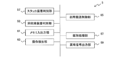
- FIG. 3 shows the function of the control unit of the deposit / withdrawal device 1.
- the deposit / withdrawal device 1 is a deposit / withdrawal device that can be used in a deposit / withdrawal unit such as an automatic teller machine of a financial institution or a ticket vending machine of a transportation facility.
- the depositing / dispensing apparatus 1 includes an operation unit 4, banknote transport units 31 to 49, a banknote discriminating unit 7, stackers 9a to 9d (collectively also referred to as stacker 9), and stacker mounting portions 13a to 13d (collectively, mounting portion 13).
- the stacker detection units 29a to 29d (collectively referred to as the stacker detection unit 29), the recovery unit 27, the recovery unit mounting unit 51, the recovery unit detection unit 28, the abnormality notification unit 53, and the storage unit 55. It is connected to the control unit 5 via the bus 2.
- the operation unit 4 is provided, for example, on the front surface of the deposit / withdrawal device 1, and includes an input screen (not shown) for inputting instructions for ticket purchase, cash deposit, etc., a deposit unit 15 for inserting banknotes, It has a withdrawal unit 17 for discharging banknotes such as refunds.
- the operation unit 4 will be described in the form of being directly provided in the deposit / withdrawal device 1 for convenience. However, when used as a deposit / withdrawal unit for an automatic teller machine, etc. And may be configured to be electrically connected to the deposit / withdrawal device 1.
- the banknote transport units 31 to 49 are paths in which a plurality of rollers (not shown) capable of rotating in the forward and reverse directions are disposed, and the banknotes are held in a predetermined direction by holding the banknotes or by frictional force between the banknotes. Transport.
- the banknote transport units 31 to 49 are further provided with a motor (not shown) that drives at least a part of the plurality of rollers, and the banknotes are bidirectionally transferred between the depositing unit 15, the stacker 9, the collection box 27, and the dispensing unit 17. It can be conveyed.
- the details of the bill transport unit 49 will be described later.
- the banknote discrimination part 7 is a discrimination apparatus which discriminates the denomination, authenticity, etc. of a banknote. Although discrimination is performed at the time of depositing and withdrawing, simple discrimination such as determining only the length of banknotes may be performed at the time of withdrawal.
- the stackers 9a to 9d are detachably provided in the stacker mounting portions 13a to 13d, respectively, as indicated by an arrow 10 in FIG. 1, and are configured so that banknotes can be accommodated therein or fed out to the outside.
- the stacker 9 can be mounted on any stacker mounting portion 13, and the internal configuration is the same.
- the stacker 9a can store 10,000 yen banknotes
- the stacker 9b can store 5,000 yen banknotes
- the stacker 9c can store 1000 yen banknotes, but have the same internal configuration.
- the stacker 9 is used as a temporary storage for temporarily storing banknotes deposited from the depositing unit 15 until the processing started by the operation is completed after the operation unit 4 starts the operation. You can also. Details of the configuration of the stackers 9a to 9d will be described later.
- the stacker 9 includes a memory 11.
- the memory 11 is a rewritable memory, and stores at least a denomination and the number of banknotes stored in the stacker 9 as storage information. Moreover, you may make it memorize
- the category of banknote is, for example, whether the banknote is a normal ticket, a damaged banknote, a suspected suspicious ticket, or a forged ticket.
- the stacker detection unit 29 is, for example, an optical sensor, and is configured to shield the light receiving unit when the stackers 9a to 9d are attached, thereby determining whether or not the stackers 9a to 9d are attached to the deposit / withdrawal device 1. Is output to the control unit 5.
- the mounting portion 51 is detachably disposed. Further, when the banknotes are collected without removing the stackers 9a to 9d from the deposit / withdrawal device 1, the collection box 27 stores the banknotes fed out from the stackers 9a to 9d. Note that even if there is room for storage inside the stacker, banknotes stored in the stacker may be stored in the collection box by an instruction from the operation unit 4.
- the collection box 27 includes a memory 25.
- the memory 25 is a rewritable memory, and stores the denomination, number, category, and the like of banknotes stored therein as storage information in association with each other.
- the memory 25 may store the date on which banknotes are stored, the identification information of the deposit / withdrawal device 1 used last time, and the like.
- the collection warehouse detection unit 28 is, for example, an optical sensor.
- the collection unit 27 is configured to receive light when the collection unit 27 is mounted on the collection unit mounting unit 51, and the light receiving unit is shielded. A signal corresponding to whether or not 27 is attached to the deposit / withdrawal apparatus 1 is output to the control unit 5.
- the abnormality notifying unit 53 is, for example, light or sound when an abnormality occurs in the stacker mounting unit 13 such as when a stacker 9 different from the setting in the control unit 5 is mounted, or when a conveyance abnormality is detected. Announce the abnormality.
- the storage unit 55 is a memory such as a ROM (Read Only Memory), a RAM (Random Access Memory), and the like.
- Information generated by the processing of the control unit 5, such as data read from the memory 11 provided in the stackers 9a to 9d, the discrimination result, and the like is recorded as appropriate. With the configuration as described above, in the depositing and dispensing apparatus 1 according to the first embodiment, various kinds of banknotes are recycled.
- the control unit 5 has functions of a stacker mounting determination unit 57, a collection box mounting determination unit 59, a memory input / output unit 61, an operation detection unit 63, a bill movement control unit 65, a discrimination processing unit 67, and an abnormal signal output unit 69. ing.
- the stacker attachment determination unit 57 determines whether or not the stacker is attached to the stacker attachment units 13a to 13d based on the signal output from the stacker detection unit 29.
- the collection storage mounting determination unit 59 determines whether or not the recovery storage 27 is mounted on the recovery storage mounting unit 51 based on a signal output from the recovery storage detection unit 28.
- the memory input / output unit 61 reads / writes the memory 11 included in the stacker 9 and the memory 25 of the collection container 27 and stores the read data in the storage unit 55.
- the operation detection unit 63 detects an operation performed by the operation unit 4.
- the bill movement control unit 65 conveys the bills in the bill conveyance unit and the stackers 9a to 9d according to the operation performed by the operation unit 4, the data read from the memory 11, the control program stored in the storage unit 55, and the like. To control.
- the discrimination processing unit 67 detects the denomination, authenticity, and the like of the banknote based on the information on the banknote detected by the banknote discrimination unit 7, performs discrimination, and stores the discrimination result in the storage unit 55 part.
- the abnormality signal output unit 69 outputs a signal that causes the abnormality signal notification unit 53 to notify the abnormality.
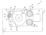
- FIG. 4 is a diagram illustrating an internal configuration of the stacker.
- the stacker 9 includes a drum 88 having a winding shaft 89 with a manual knob 87 inside a housing 80.
- One end of each of the tapes 96 and 98 is fixed to the winding shaft 89 of the drum 88.
- the tapes 96 and 98 are both band-like films.
- the tape 96 is stretched around the tension roller 91 and the other end is held by the holding roller 83.
- the holding roller 83 includes a torsion spring 21 and a torque limiter 22.
- the tape 96 is fed out from the holding roller 83 or is fed into the holding roller 83.
- the tape 96 is wound around the drum 88 or fed out from the drum 88.
- the tape 98 is stretched over the rotation transmission roller 92 and the guide roller 93, and the other end is held by the holding roller 86.
- the holding roller 86 includes a torsion spring 84 and a torque limiter 85.
- the tape 98 is fed out from the holding roller 86 or is fed into the holding roller 86.
- the tape 98 is wound around the drum 88 or fed out from the drum 88.
- a bill detection sensor 97 for detecting passage of bills is disposed, and a detection signal is sent to the control unit 5 in a state where the stacker 9 is mounted on the depositing / dispensing device 1.
- the tape 96 is preferably transparent or translucent.
- the rotation detection plate 95 is fixed to the rotation shaft 94 of the rotation transmission roller 92 and is provided to be rotatable in synchronization with the rotation transmission roller 92. In a state where the rotation sensor 99 is provided so as to sandwich the rotation detection plate 95 and the stacker 9 is attached to the depositing / dispensing device 1, a signal corresponding to the rotation speed of the rotation transmission roller 92 is sent to the control unit 5.
- the stacker 9 has a stepping motor 79.
- the holding rollers 83 and 86, the rotation transmission roller 92, and the drum are connected via gears (not shown). Rotate 88 in both forward and reverse directions. Note that the rotation of the stepping motor 79 is controlled by the control unit 5 based on signals from the banknote detection sensor 97 and the rotation sensor 99.
- the banknotes conveyed between the tension roller 91 and the rotation transmission roller 92 in the stacker 9 are held on the take-up shaft 89 of the drum 88 while being sandwiched between the tapes 96 and 98. It is wound up. Further, the banknotes fed out from the drum 88 are fed out from between the tension roller 91 and the rotation transmission roller 92 while being sandwiched between the tapes 96 and 98.
- the banknote conveyance part inside the stacker 9 demonstrated above it simplified and has shown as the banknote conveyance part 49 in FIG.
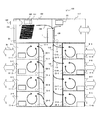
- FIG. 5 is a diagram showing the configuration of the replenishing and collecting apparatus 100
- FIG. 6 is a block diagram showing the configuration of the replenishing and collecting apparatus 100
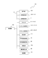
- FIG. 7 is a block diagram showing the function of the control unit 105.
- the replenishment / collection device 100 is a device for replenishing the stacker 9 with banknotes or collecting banknotes from the stacker 9.
- the replenishing and collecting apparatus 100 includes an operation unit 104, a storage unit 102, banknote transport units 108 to 116, a banknote discriminating unit 7, a stacker 9-1 to 9-8 (collectively referred to as a stacker 9), and a stacker mounting unit 13-1.
- stacker mounting unit 13 (collectively referred to as the stacker mounting unit 13), stacker detection units 29-1 to 29-8 (collectively referred to as the stacker detection unit 29), the recovery container 117, the recovery container mounting part 51, and the recovery container It has a detection unit 28, an abnormality notification unit 53, and a storage unit 101, and is connected to the control unit 105 via the system bus 2.
- the operation unit 104 is provided, for example, on the front surface of the replenishing and collecting apparatus 100, and has an input screen (not shown) for inputting instructions for replenishing bills to the stacker 9 and collecting bills from the stacker 9. Yes.
- the storage box 102 is a storage unit that stores banknotes to be replenished in the stacker 9.
- the banknote transport sections 108 to 116 are paths in which a plurality of rollers (not shown) capable of rotating in the forward and reverse directions are arranged. The banknotes are held in a predetermined direction by holding the banknotes or by frictional force between the banknotes. Transport.
- the banknote transport sections 108 to 116 are further provided with a motor (not shown) that drives at least a part of the plurality of rollers so that banknotes can be transported between the storage box 102, the stacker 9, and the collection box 117.
- the stackers 9-1 to 9-8 are detachably attached to the stacker mounting portions 13-1 to 13-8 as indicated by the arrow 10 in FIG.
- the stackers 9-1 to 9-8 can be mounted on any stacker mounting portion, and have the same configuration as the stackers 9a to 9d.
- the stackers 9-1 to 9-8 are provided with memories 11-1 to 11-8, respectively.
- the collection box 117 is a storage unit that stores banknotes collected from the stackers 9-1 to 9-13, includes a memory 25, and is detachably disposed on the collection box mounting unit 51.
- the configuration of the collection box 117 is the same as that of the collection box 27, and can be used as the collection box 27 of the deposit / withdrawal apparatus 1.
- the storage unit 101 is a memory such as a ROM or a RAM.
- the storage unit 101 is a control program for the replenishing and collecting apparatus 100, denominations corresponding to the stackers 9-1 to 9-8, data relating to banknote transport, 8 appropriately records information generated from the processing of the control unit 105, such as data read from the memory 11 provided in FIG.
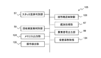
- the function of the control unit 105 will be described with reference to FIG. Components having the same functions as those of the deposit / withdrawal apparatus 1 are denoted by the same reference numerals, and detailed description thereof is omitted.
- the control unit 105 includes a stacker mounting determination unit 57, a collection storage mounting determination unit 59, a memory input / output unit 124, an operation detection unit 126, a bill movement control unit 128, a discrimination processing unit 67, an abnormal signal output unit 69, and a storage control unit. It has 134 functions.
- the memory input / output unit 124 reads / writes the memory 11 and the memory 25 while referring to the data stored in the storage unit 101, and stores the written data in the storage unit 101.
- the operation detection unit 126 detects an operation performed by the operation unit 104.
- the bill movement control unit 128 is controlled by the bill transport units 108 to 116 and the stacker 9 according to the operation performed by the operation unit 104, the data read from the memory 11 and the memory 25, the control program stored in the storage unit 101, and the like. To control the movement of bills.
- the storage control unit 134 controls a transport mechanism (not shown) in accordance with an instruction from the operation unit 104 and controls to feed out banknotes from the storage 102. Note that banknotes 102 can be replenished from outside as indicated by arrows 103.
- FIG. 8 is a flowchart for explaining an operation method of the deposit / withdrawal apparatus 1 according to the first embodiment
- FIG. 9 is a flowchart for explaining a banknote replenishment process in the replenishment / collection apparatus 100
- FIG. 10 is a deposit / withdrawal in the deposit / withdrawal apparatus 1.
- FIG. 11 is a flowchart for explaining banknote collection processing in the replenishment collection apparatus 100.
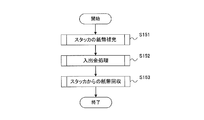
- the stacker 9 detachably attached to both the deposit / withdrawal device 1 and the replenishment / collection device 100 is first replenished with banknotes by the replenishment / recovery device 100 (S151). This process is usually performed in the backyard before the start of the business of performing the deposit / withdrawal process using the deposit / withdrawal apparatus 1.
- the stacker 9 is attached to the deposit / withdrawal apparatus 1 and a deposit / withdrawal process is performed (S152).
- S152 deposit / withdrawal process
- the stacker 9 is removed from the deposit / withdrawal apparatus 1
- the stacker 9 is attached to the replenishment / collection apparatus 100 again and the internal banknotes are collected (S153).
- the collection of banknotes is usually performed at the backyard after the deposit / withdrawal processing is completed.
- the replenishment / collection apparatus 100 repeats the detection until a replenishment instruction is input through the operation unit 104 (S161). That is, the operation detection unit 126 of the control unit 105 monitors whether or not a signal based on an operation for replenishing banknotes is input from the operation unit 104. At this time, the operation unit 104 inputs, for example, information indicating at least one of the stackers 9-1 to 9-8 to be replenished, the denomination to be replenished, and the number thereof.
- the stacker mounting determination unit 57 monitors until a signal indicating that the stacker 9 is mounted is detected from the stacker detection unit 29 corresponding to the stacker 9 to be supplemented (S162: No). If the stacker instructed to input replenishment from the operation unit 104 is not mounted, an error display or a display for prompting the mounting may be displayed on the operation unit.
- S162: Yes banknotes are fed out from the storage 102. The fed banknotes are subjected to banknote discrimination by the banknote discrimination unit 7 (S163).
- the storage control unit 134 transmits a control signal to a transport mechanism (not shown) according to the denomination and the number of sheets input by the operation unit 104 and feeds the banknotes to the banknote transport unit 108.
- the banknote discriminating unit 7 outputs a signal corresponding to the denomination, authenticity, etc. of the banknote by an unillustrated discrimination mechanism having an optical sensor or the like provided therein, and the discrimination processing unit 67 discriminates (S163). .
- a banknote transport unit (not shown) heading from the banknote transport unit 116 to the banknote discrimination unit 7, for example. It conveys to 117.
- the banknotes identified as suitable for use by the discrimination are sequentially stored in the stacker 9 to be replenished (S164).
- the control unit 105 monitors the storage until the storage is completed by the storage control unit 134, the bill conveyance control unit 128, the discrimination processing unit 67, and the like (S165).
- the memory input / output unit 124 stores the denomination, the number, etc. of the replenished banknotes in the memory 11 of the stacker 9 replenished banknotes (S166).
- the control unit 105 notifies the completion by displaying the completion on a display unit (not shown) of the operation unit 104 (S167), and ends the replenishment process.
- a plurality of types of denominations may be stored in the storage 102.
- data indicating which denomination is stored in which stacker 9-1 to 9-8 is stored in the storage unit 101 in advance, and according to the stored data and the discrimination result in the banknote discrimination unit 7.
- the banknote transport control unit 128 may control to change the stacker 9 that is the banknote transport destination.
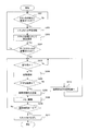
- the stacker 9 is removed when the replenishment / recovery device 100 finishes replenishment and is mounted on the deposit / withdrawal device 1. As shown in FIG. 10, the deposit / withdrawal apparatus 1 performs monitoring until the stacker 9 is newly attached (S171: No). That is, the stacker mounting determination unit 57 of the control unit 5 monitors until a signal indicating that the stacker 9 is mounted is sent from any of the stacker detection units 29a to 29d.
- the storage information including the denomination and the number of banknotes stored in the stacker 9 is read from the memory 11 of the mounted stacker 9 (S172). That is, the memory input / output unit 61 accesses the memory 11, reads stored information such as the denomination and number of banknotes stored, and stores the stored information in the storage unit 55. At this time, the storage unit 55 stores in advance which stacker 9 in which the denomination is stored in each stacker mounting unit 13 is associated. The banknote transport control unit 65 determines whether or not the denomination acquired from the memory 11 is the set correct denomination stored in the storage unit 55 in advance (S173).
- an abnormality signal is transmitted from the abnormality signal output unit 69, and the abnormality notification unit 53 notifies the abnormality (S182). If the denomination is correct (S173: Yes), it is determined whether or not the stackers 9a to 9d are mounted on all the stacker mounting portions 13a to 13d (S174). If there is a stacker mounting part 13 that is not mounted, the process returns to S171. Note that information on stackers that require mounting is stored in the storage unit 55 via the input unit 4 or the like, so that the process proceeds to the next processing step (S175) even if all stackers are not mounted. good.
- the operation detection section 63 starts detecting an operation from the operation section 4 and monitors until there is an operation (S175: No). .
- the operation detection unit 63 detects an operation from the operation unit 4 (S175: Yes)
- information corresponding to the detected operation is stored in the storage unit 55.
- the banknote transport units 31 to 49 perform transport according to the operation from the operation unit 4, and in the process, the discrimination processing unit 67 is used for depositing or withdrawing transported based on the signal from the banknote discrimination unit 7.
- the banknotes are identified (S176), and it is determined whether or not they are normal banknotes, that is, whether or not the banknotes are not suitable for withdrawal, such as those with suspected tickets, tears, breakage, dirt, etc. (S177). If it is determined that the banknote is not normal (S177: No), the banknote deposited from the depositing section 15 is discharged from the withdrawal section 17, and the banknote fed from the stacker 9 is stored in the collection box 27. (S183). When it is determined that the banknote is normal, the banknote is stored or withdrawn (S178). At this time, the discrimination processing unit 67 stores information regarding discrimination in the storage unit 55. The details of the operation from when the operation detection unit 63 detects the operation of the operation unit 4 until the storage or withdrawal of banknotes is completed (S175 to S178) will be described later.
- the memory input / output unit 61 is based on the contents of the memory 11 stored in the storage unit 55 and information stored in the discrimination processing unit 67, for example, and the denominations stored in the stackers 9a to 9d and the collection box 27. And the number of images are calculated and stored in the storage unit 55 in association with each other. Here, if any of the stackers 9a to 9d or the number of sheets stored in the collection box 27 is changed, the contents of the corresponding memory 11 or 25 are rewritten (S179). Note that the memory input / output unit 61 may appropriately write predetermined information in the memories 11 and 25 as necessary. The above operation is repeated until the operation time of the deposit / withdrawal device 1 ends (S180: No). When the operation time ends, the stacker 9 is removed (S181), and the process ends.
- S175 to 178 will be described according to the type of deposit / withdrawal process.
- 10,000 yen bills, 5,000 yen bills, and thousand yen bills are stored in the stackers 9a to 9c, respectively.
- the case where the stacker 9d is used as a temporary storage assuming that the stacker 9d can store more than a predetermined number of sheets when the depositing / dispensing apparatus 1 starts business.
- the operation detection unit 63 detects the insertion of a banknote in the depositing unit 15 of the operation unit 4
- the depositing unit 15 feeds the banknotes one by one to the banknote transport unit 31 by a mechanism (not shown).
- a banknote is conveyed via the banknote conveyance parts 31, 32, and 33 by control of the banknote conveyance control part 65, and passes the banknote discrimination part 7.
- the banknote transporting unit 35, 36, 38, 41 causes the stacker 9c to It is stored in. At this time, in the stacker 9c, as shown in FIG. 4, the banknote is wound around the drum 88 while being sandwiched between the tapes 96 and 98.
- the banknote becomes a temporary storage through the banknote transport path 35, 36, 39. Is temporarily stored in the stacker 9d.
- the banknote transport control unit 65 causes the banknotes to be fed again from the stacker 9d. That is, in the stacker 9d, as shown in FIG. 4, the stepping motor 79 is controlled by the bill conveyance control unit 65, so that the bill is wound around the drum 88 and stored while being sandwiched between the tapes 96 and 98. The Thereafter, the sheet is rewound again and fed out between the tension roller 91 and the rotation transmission roller 92.
- banknote is discharged
- the banknote is stored in the collection box 27 via the banknote transport units 39, 35, and 37 after completion of the deposit process. .
- the banknote transport control unit 65 performs the operation from the stored stacker 9c or stacker 9d.
- the amount deposited by the operation is fed out and discharged from the dispensing unit 17 via the banknote transport paths 38, 36, 35, 33, 47 and the like.
- a banknote is dispensed from the dispensing unit 17 as change. It is assumed that a withdrawal instruction is given from the banknote transport control unit 65 to, for example, the banknote transport unit 49 of the stacker 9b when there is a change withdrawal during the deposit process.
- the necessary number of sheets is unwound from the drum 88 based on the instruction of the banknote transport control section 65 and fed out, and the withdrawal section 17 is sequentially passed through the banknote transport sections 43, 40, 38, 36, 35, 33, 47.
- the banknote discrimination part 7 performs simple discrimination such as length discrimination.
- a banknote transport unit and a banknote transport unit 42, 40, 38, 36, 37 (not shown) that connect the banknote transport unit 33 and the banknote transport unit 42 are connected. It is preferable to store in the collection
- the banknote transport control unit 65 causes the instructed stacker 9 to feed out the banknotes sequentially stored, and the banknote transport units 36 to 45.
- the bills are transported and stored in the collection box 27 via.
- the memory input / output unit 61 causes the memory 25 to store the denomination, the number, and the category of the stored banknotes in association with each other.
- the memory input / output unit 61 may appropriately write predetermined information in the memory 25 as necessary.
- the banknote information stored in the memory 25 may be acquired from the memory 11 of the stacker 9.
- a stacker 9 dedicated for replenishment is provided at a position where banknotes can flow from the upper part of the banknote discrimination unit 7 of the banknote transport unit 33, for example. You may make it replenish a banknote to the stackers 9a-9d via the banknote conveyance path 33,35,36,39,41,43,45.
- FIG. 11 is a flowchart showing banknote collection processing by the replenishment collection apparatus 100.
- the stackers 9a to 9d are removed from the deposit / withdrawal device 1 and mounted on any of the stacker mounting portions 13-1 to 13-8 of the replenishment / collection device 100.
- the operation detection unit 126 continues monitoring until an instruction to collect banknotes is received from the operation unit 104 (S191: No).
- the stacker attachment determination unit 57 continues monitoring until the collection target stacker 9 for which the collection instruction has been issued is attached, and the collection case determination unit 59 attaches the collection case 117. Monitoring is continued until it is made (S192: No).
- the banknote transport control unit 128 determines the collection target stacker 9. Then, the banknote is rewound from the drum 88 and the banknote is fed out.
- the discrimination processing unit 67 Based on the signal according to, the discrimination processing unit 67 performs discrimination (S193). At this time, the discrimination processing unit 67 stores the discrimination results such as the denomination, number of sheets, and authenticity of the banknotes in the storage unit 101.
- the control unit 105 monitors the collection by the banknote conveyance control unit 128, the discrimination processing unit 67, and the like until the collection is completed (S194: No). When it is detected that the collection is completed (S194: Yes), the memory input / output unit 124 resets the memory 11 of the stacker 9 that collects the banknotes. In addition, the memory input / output unit 124 stores the denomination, the number, and the like of the collected banknotes in the memory 25 with reference to the discrimination result stored in the storage unit 101 (S195). The control unit 105 notifies the completion by displaying the completion on a display unit (not shown) of the operation unit 104 (S196), and ends the collection process.
- the stacker 9 detachable from both the depositing / dispensing apparatus 1 and the replenishing / collecting apparatus 100 according to the first embodiment can be attached to the drum 88 with the banknotes sandwiched between the two tapes 96 and 98.
- a banknote is accommodated by winding.
- the bills are fed out of the stacker 9 by rewinding the tapes 96 and 98 sandwiching the bills from the drum 88.
- storage information such as the denomination and number of banknotes stored therein is stored in the memory 11.
- the stacker 9 is replenished with banknotes by the replenishing and collecting apparatus 100, and storage information of the stored banknotes is stored in the memory 11.
- the stacker 9 After being removed from the replenishment / collection device 100, the stacker 9 is mounted on the deposit / withdrawal device 1 and a deposit / withdrawal process is performed. When the deposit / withdrawal process is completed and the stacker 9 is removed from the deposit / withdrawal apparatus 1, it is attached to the replenishment / collection apparatus 100 again to collect the banknotes inside. At this time, the memory 11 is reset to an initial state.
- the memory 11 is an example of the first storage unit of the present invention
- the stacker 9 is an example of a bill storage unit
- the stacker mounting unit 13 is an example of a mounting unit.
- the stacker detection unit 29 is an example of a detection unit
- the memory input / output unit 61 is an example of a reading unit and an update unit
- the storage unit 55 is an example of a second storage unit
- the bill conveyance control unit 65 is The storage discriminating unit is an example
- the operation unit 4 is an example of an instruction input unit
- the banknote transport units 31 to 49 are examples of a transport unit.
- the operation detection unit 126 is an example of a replenishment instruction acquisition unit of the present invention
- the storage control unit 134 and the banknote transport control unit 128 are examples of a replenishment unit and a collection unit
- the memory input / output unit 124 is an example of a recording unit.
- the detachable stacker that can be used as a stacker for banknotes of a plurality of denominations without performing mechanical adjustment or the like.
- the detachable stacker that can be used as a stacker for banknotes of a plurality of denominations without performing mechanical adjustment or the like.
- it is possible to detect erroneous attachment to the depositing / dispensing apparatus 1 by providing the memory 11 for storing storage information including the denomination and number of banknotes stored.
- the storage information of the banknote accommodated in the inside can be read by reading the memory 11 by the deposit / withdrawal device 1 and the replenishment collection device 100, the timing of replenishment and collection can be accurately achieved.
- the bottom area of the storage unit during storage can be made smaller than the size of the banknotes, and the deposit / withdrawal device 1 and the replenishment collection device 100 can be downsized. Can be realized. Further, at the time of feeding, a detachable stacker that can prevent double feed can be provided.
- the banknote can be replenished only by mounting the stacker 9 in which the banknote is replenished by the replenishment / collection apparatus 100 in advance. For collection, the stacker 9 can be removed and the replenishment collection apparatus 100 can perform collection. Therefore, although the banknotes are sequentially stored or delivered by the stacker 9, the work before and after the business by the depositing / dispensing device 1 can be performed in a short time. Furthermore, even when it is necessary to replenish banknotes during business hours, it is only necessary to remove and insert cassettes, so that it is possible to prevent service degradation for customers.
- the replenishing and collecting apparatus 100 it is possible to replenish banknotes to a plurality of stackers 9 at the same time by differentiating with the banknote discriminating apparatus 7 in a state where various denominations are stored in the storage 102, thereby improving work efficiency. Is possible.
- the stacker 9 can be used with a plurality of denominations, the number of stackers 9 to be prepared can be minimized, and the cost can be reduced.
- chamber 117 can be combined with the collection
- FIG. 12 is a flowchart showing the deposit / withdrawal process of the deposit / withdrawal apparatus according to the second embodiment.
- the denominations of banknotes stored in the stacker 9 to be mounted on each stacker mounting portion 13 are set in advance, but in the second embodiment, the memory 11
- the conveyance of banknotes is controlled according to the denomination read from. That is, as shown in FIG. 12, when the memory input / output unit 61 reads the denomination from the storage information in the memory 11 in S202, the memory input / output unit 61 reads the denomination and the identification information of the stacker storage units 13a to 13d. Are stored in the storage unit 55 in association with each other.
- the bill conveyance control unit 65 sets the conveyance based on the denominations stored in the storage unit 55 and the information on the stacker storage units 13a to 13d (S203). When the denominations are set for all the stacker mounting portions 13, the process proceeds to S204.
- the abnormality notifying unit 53 may notify, for example, the abnormality of the banknote conveying units 31 to 49.
- the stacker mounting portion 13 where the stacker 9 is mounted is located at the location of the stacker 9 by using the denomination recorded in the memory 11 of the stacker 9. It can be set as a denomination to be stored or drawn out. Therefore, since the stacker mounting portion 13 for mounting the stacker 9 is not limited, the usability can be further improved, for example, it can be used for a banknote depositing and dispensing machine of a plurality of types of currencies.
- the present invention is not limited to the embodiment described above, and various configurations or embodiments can be adopted without departing from the gist of the present invention.
- the configuration of the stacker 9 is not limited to the above, and the stacker 9 can be used as a stacker of the present invention as long as it can store and feed out bills of different sizes.
- the contents of the memories 11 and 25 are not limited to the above, and may include other elements.
- recovery apparatus 100 is not limited above, If it has the same effect, it is the scope of the present invention.
Landscapes
- Physics & Mathematics (AREA)
- General Physics & Mathematics (AREA)
- Business, Economics & Management (AREA)
- Accounting & Taxation (AREA)
- Finance (AREA)
- Engineering & Computer Science (AREA)
- Mechanical Engineering (AREA)
- Pile Receivers (AREA)
- Financial Or Insurance-Related Operations Such As Payment And Settlement (AREA)
Abstract
入出金装置1及び補充回収装置100の両方に着脱可能なスタッカ9は、2枚のテープ96、98に紙幣を挟持した状態で、ドラム88に巻き付け、または巻き戻すことにより紙幣を収納及び繰り出す。スタッカは、サイズの異なる紙幣のスタッカとして共用でき、内部に収納している紙幣の金種、枚数等の収納情報がメモリ11に記憶されている。スタッカ9は、まず、補充回収装置100で紙幣を補充され、収納された紙幣の収納情報がメモリ11に記憶される。補充回収装置100から取り外された後に、スタッカ9は入出金装置1に装着されて、入出金処理が行われる。メモリ11は、入出金の処理ごとに更新される。入出金処理が終了し、スタッカ9が入出金装置1から取り外されると、再び補充回収装置100に装着されて内部の紙幣を回収される。これにより、全金種でスタッカ9を共用できるとともに、入出金装置の紙幣の補充、回収を短時間で行える。
Description
本発明は、入出金装置、補充回収装置及び、入出金装置の運用方法、に関する。
例えば、切符を発売する券売機等では、券を購入するための紙幣が入金されると、真贋、金種、破損の度合いなどを鑑別し、つり銭として出金可能である紙幣は金種別に格納される。これらの紙幣は、積み重ねて集積され格納される。(例えば、特許文献1参照)。
また、金融機関の自動預け払い機等では、入金され、金種が判別された紙幣を順次収納し、取引が成立するまでいったん保留し、取引成立後順次放出する機能を有する一時保管庫を有しているものがある。この一時保管庫においては、テープとともに紙幣を巻き取る回転ドラムが配置されており、回転ドラムを一方向に回転させて紙幣を回転ドラムに巻き取って一時収納し、逆回転させることにより、巻き取った紙幣を排出するようにしている(例えば、特許文献2参照)。
さらに、複数の金種の紙幣をそれぞれ収納する収納部に、2枚のテープの間に紙幣を挟んで巻き取る正逆回転可能なドラムを設けるようにした例も開示されている(例えば、特許文献3参照)。
しかしながら、例えば特許文献1に記載のように、つり銭として利用する紙幣を積み重ねて集積した状態で収納すると、繰り出し時にダブルフィード等の搬送不良を起こすことがある。また、ダブルフィードによって、紙幣の枚数管理に誤差が生じる場合がある。よって、紙幣収納部の紙幣の繰出し部に、摩擦またはギャップを管理することによる繰出し機構を設けなければならない。このためには、それぞれの紙幣サイズに合わせて個々に調整された専用の収納部および繰出し部とする必要があり、取扱紙幣を変更する際には、機械的な調整が不可欠であるため、サイズの異なる紙幣には共用できないという使い勝手の悪さがある。
一方、特許文献2、3に記載のように、テープとともに紙幣をドラムに巻きつけて収納する方式では、紙幣のサイズが異なる場合にも兼用することが可能である。しかし、ドラムに巻きつけて収納する方式では、収納部につり銭用の紙幣を補充したり、収納された紙幣を回収したりするためには、紙幣を順次収納または排出させなくてはならない。このため、業務開始前、及び終了後の作業に時間がかかるという問題がある。また、金融機関等で業務時間中に紙幣の補充または回収を行う必要が生じた場合等には、作業によるサービスの停止を短時間で済ませることができず、顧客に対するサービスの低下につながるという問題がある。
そこで本発明は、紙幣のサイズにかかわらず同一の構成で、紙幣の補充または回収を効率よく行うことが可能な入出金装置、補充回収装置及び、入出金装置の運用方法を提供することを目的とする。
本発明の態様のひとつである入出金装置は、紙幣の入金および出金を行う入出金装置であって、一以上の金種の紙幣を収納可能で、収納している紙幣の金種を含む収納情報を有する第1の記憶部を有し、紙幣を収納及び排出する着脱可能な紙幣収納部と、前記紙幣収納部を装着する装着部と、前記装着部に前記紙幣収納部が装着されているか否かを検知する検知部と、前記検知部が前記紙幣収納部の装着を検出すると、前記第1の記憶部より、前記紙幣の金種を読み出す読出部と、前記装着部と、前記装着部に装着される前記紙幣収納部に収納させる前記紙幣の金種とを関連付けて記憶させておく第2の記憶部と、前記読出部が読み出した前記紙幣の金種が、前記第2の記憶部に前記紙幣収納部の装着が検知された前記装着部と関連付けて記憶されている金種と適合するものであるか否かを判別する収納部判別部と、前記収納判別部が適合すると判別すると、前記紙幣の入金または出金の指示の受付を開始する指示受付部と、前記指示に基づき前記紙幣を搬送する搬送部と、を有することを特徴としている。
別の態様のひとつである入出金装置は、一以上の金種の紙幣を収納可能で、収納している紙幣の金種を含む収納情報を有する第1の記憶部を有し、紙幣を収納及び排出する着脱可能な紙幣収納部と、前記紙幣収納部を装着する装着部と、前記装着部に前記紙幣収納部が装着されているか否かを検知する検知部と、前記検知部が前記紙幣収納部の装着を検出すると、前記第1の記憶部より、前記金種を読み出す読出部と、前記読出部が読み出した前記金種を、前記装着部と関連付けて記憶させる第2の記憶部と、前記第2の記憶部に前記金種と前記装着部とが関連付けて記憶されると、前記紙幣の入金または出金の指示の受付を開始する指示受付部と、前記第2の記憶部の記憶内容と、前記指示に基づき前記紙幣の搬送を行う搬送部と、を有することを特徴としている。
さらに別の態様のひとつである紙幣補充回収装置は、一以上の金種の紙幣を収納可能で、収納している紙幣の金種及び枚数を含む収納情報を有する第1の記憶部を有し、紙幣を収納及び排出する着脱可能な紙幣収納部と、前記紙幣収納部を装着する装着部と、前記装着部に前記紙幣収納部が装着されているか否かを検知する検知部と、前記検知部が前記紙幣収納部の装着を検出すると、前記紙幣収納部に補充する金種と枚数を含む補充指示を取得する補充指示取得部と、前記補充指示に基づき前記紙幣収納部に紙幣を補充する補充部と、前記補充指示に応じて補充された前記紙幣の金種及び枚数を判別する紙幣鑑別部と、前記紙幣鑑別部において判別された前記紙幣の金種及び枚数に基づき、前記第1の記憶部に前記収納情報を記録する記録部と、を有することを特徴としている。
また、別の態様のひとつである入出金装置の運用方法は、紙幣の入金および出金を行う入出金装置の運用方法であって、一以上の金種の紙幣を収納可能で、収納している紙幣の金種を含む収納情報を有する第1の記憶部を有し、前記入出金装置が備えている装着部に着脱可能で紙幣を収納及び排出する紙幣収納部が、前記装着部に装着されているか否かを前記入出金装置が備えている検知部が検知する検知工程と、前記第1の記憶部より、前記紙幣の金種を読み出す読出工程と、前記読出工程において読み出した前記金種が、前記入出金装置が備えている第2の記憶部に前記紙幣収納部の装着が検知された前記装着部と関連付けて記憶されている紙幣の金種と適合するものであるか否かを判別する収納部判別工程と、前記収納部判別工程において適合すると判別されると、前記紙幣の入金または出金の指示の受付を開始する指示受付工程と、前記指示に基づき前記紙幣を搬送する搬送工程と、を有することを特徴としている。
本発明によれば、全金種で紙幣収納繰出部を共用できるとともに、入出金装置の紙幣の補充、回収を短時間で行える入出金装置運用方法、入出金装置及び補充回収装置を提供することができる。
(第1の実施の形態)
以下、本発明の実施の形態を図面に基づいて説明する。まず、第1の実施の形態による入出金装置1の構成について、図1から図3を参照しながら説明する。図1は、第1の実施の形態による入出金装置1の構成を示す図、図2は、入出金装置1の構成を示すブロック図、図3は、入出金装置1の制御部の機能を示すブロック図である。
以下、本発明の実施の形態を図面に基づいて説明する。まず、第1の実施の形態による入出金装置1の構成について、図1から図3を参照しながら説明する。図1は、第1の実施の形態による入出金装置1の構成を示す図、図2は、入出金装置1の構成を示すブロック図、図3は、入出金装置1の制御部の機能を示すブロック図である。
図1、図2に示すように、入出金装置1は、例えば金融機関の自動預け払い機や、交通機関の券売機等の入出金部に用いることのできる入出金装置である。入出金装置1は、操作部4、紙幣搬送部31~49、紙幣鑑別部7、スタッカ9a~9d(まとめて、スタッカ9ともいう)、スタッカ装着部13a~13d(まとめて、装着部13ともいう)、スタッカ検知部29a~29d(まとめて、スタッカ検知部29ともいう)、回収庫27、回収庫装着部51、回収庫検知部28、異常報知部53、記憶部55を有し、システムバス2を介して制御部5に接続されている。
操作部4は、例えば、入出金装置1の前面に設けられ、切符の購入や現金の預け払いなどのための指示を入力する不図示の入力画面や、紙幣を投入する入金部15、つり銭や払い戻し等の紙幣を排出する出金部17などを有している。なお、操作部4については、便宜上入出金装置1に直接設けられる形態について説明するが、自動預け払い機等の入出金部として利用される場合には、自動預け払い機等の本体部に設けられ、入出金装置1と電気的に接続されるような構成となることもある。
紙幣搬送部31~49は、正逆回転可能な複数のローラ(図示せず)を配置された経路であり、紙幣を挟持して、または紙幣との間の摩擦力等により紙幣を所定方向に搬送する。紙幣搬送部31~49にはさらに、それら複数のローラの少なくとも一部を駆動する不図示のモータを設け、紙幣を入金部15、スタッカ9、回収庫27および出金部17の間を双方向に搬送できるように構成する。なお、紙幣搬送部49の詳細については後述する。紙幣鑑別部7は、紙幣の金種、真贋等を判別する鑑別装置である。入金時も出金時も鑑別を行うが、例えば出金時には、紙幣の長さのみを判別するなど簡易の判別としてもよい。
スタッカ9a~9dは、図1の矢印10のようにスタッカ装着部13a~13dにそれぞれ着脱可能に設けられ、内部に紙幣を収納し、または外部へ紙幣を繰り出し可能に構成される。スタッカ9は、いずれのスタッカ装着部13にも装着可能であり、内部の構成は同一である。例えば、スタッカ9aは、一万円紙幣、スタッカ9bは、五千円紙幣、スタッカ9cは、千円紙幣をそれぞれ収納することができるが、互いに同一の内部構成である。スタッカ9は、例えば、操作部4において操作が開始されてから、その操作により開始された処理が終了するまで、入金部15から入金された紙幣を一時的に保管する一時保管庫として使用することもできる。スタッカ9a~9dの構成の詳細は後述する。
スタッカ9は、メモリ11を備えている。メモリ11は、書き換え可能なメモリであり、収納情報として、スタッカ9の内部に収納されている紙幣の少なくとも金種と枚数とを関連付けて記憶している。また、収納情報として、紙幣のカテゴリ、収納した年月日、前回用いた入出金装置1の識別情報などを記憶するようにしてもよい。なお、紙幣のカテゴリとは、例えば、紙幣が正常券であるか、破損した損券であるか、真贋が疑わしい疑券であるか、偽造券であるか等である。また、例えば、入金された紙幣を一時的に保管する一時保管庫として利用する際には、その旨を示す情報を記憶するようにしてもよい。
スタッカ検知部29は、例えば光学センサであり、スタッカ9a~9dが装着されると受光部が遮蔽されるような構成とすることにより、スタッカ9a~9dが入出金装置1に装着されたか否かに応じた信号を制御部5に出力する。
回収庫27は、スタッカ9a~9dの少なくともいずれか一つに収納されている紙幣の枚数が十分で、それ以上収納する必要がないと判断された紙幣、出金部17で取り忘れられた紙幣、紙幣鑑別部7で出金紙幣には適さない(破れ、破損、汚れ等がある場合)と判別された紙幣、つり銭として利用しない紙幣(高額紙幣)等を収納する収納部であり、回収庫装着部51に着脱可能に配置される。また、回収庫27は、入出金装置1からスタッカ9a~9dを取り外さずに紙幣を回収するときに、スタッカ9a~9dから繰り出された紙幣を収納する。なお、スタッカ内部に収納の余裕があった場合であっても、操作部4からの指示によりスタッカ内部に収納されている紙幣を回収庫に収納させるようにしても良い。
回収庫27は、メモリ25を備えている。メモリ25は、書き換え可能なメモリであり、収納情報として内部に収納されている紙幣の金種、枚数、カテゴリ等を、互いに関連付けて記憶している。メモリ25は、紙幣を収納した年月日、前回用いた入出金装置1の識別情報などを記憶するようにしてもよい。回収庫検知部28は、例えば光学センサであり、回収庫27が回収庫装着部51に装着されると受光部が遮蔽され、未装着時には光を受光するような構成とすることにより、回収庫27が入出金装置1に装着されたか否かに応じた信号を制御部5に出力する。
異常報知部53は、スタッカ装着部13に、制御部5における設定と異なるスタッカ9が装着された場合等の異常が生じた際や、搬送異常が検知された場合などに、例えば光、音などにより異常を報知する。記憶部55は、ROM(Read Only Memory)、RAM(Random Access Memory)等のメモリであり、入出金装置1の制御プログラムや、スタッカ9a~9dに対応する金種の設定、紙幣の搬送に関するデータ、スタッカ9a~9dに設けられたメモリ11から読取ったデータ、鑑別結果等、制御部5の処理に伴って生成される情報を適宜記録する。以上のような構成により、第1の実施の形態による入出金装置1においては、多種の紙幣をリサイクルする。
図3を参照しながら、制御部5の機能について説明する。制御部5は、スタッカ装着判別部57、回収庫装着判別部59、メモリ入出力部61、操作検出部63、紙幣移動制御部65、鑑別処理部67、異常信号出力部69の機能を有している。スタッカ装着判別部57は、スタッカ検知部29が出力する信号に基づき、スタッカ装着部13a~13dにスタッカが装着されたか否かを判別する。回収庫装着判別部59は、回収庫検知部28が出力する信号に基づき、回収庫27が回収庫装着部51に装着されたか否かを判別する。
メモリ入出力部61は、スタッカ9が有するメモリ11、及び回収庫27のメモリ25の読み書きを行うとともに、読取ったデータを記憶部55に格納する。操作検出部63は、操作部4で行われた操作を検出する。紙幣移動制御部65は、操作部4で行われた操作、メモリ11から読み出したデータ、及び記憶部55に記憶された制御プログラム等に応じて、紙幣搬送部及びスタッカ9a~9dの紙幣の搬送を制御する。鑑別処理部67は、紙幣鑑別部7が検出した紙幣に関する情報に基づき、紙幣の金種、真贋等を検知し、鑑別を行うとともに、鑑別結果を記憶部55部に格納する。異常信号出力部69は、入出金装置1の異常が検知されると、異常信号報知部53に異常を報知させる信号を出力する。
ここで、図4を参照しながらスタッカ9の内部構成について説明する。図4は、スタッカの内部構成を示す図である。図4に示すように、スタッカ9は、筐体80の内部に、手動用ノブ87を備えた巻取軸89を有するドラム88を備えている。ドラム88の巻取軸89には、テープ96、98のそれぞれの一端がともに固定されている。テープ96、98は、いずれも帯状のフィルムである。テープ96は、テンションローラ91に掛け渡されて、他端を保持ローラ83に保持されている。なお、保持ローラ83は、トーションスプリング21およびトルクリミッタ22を備えている。テープ96は、保持ローラ83から繰り出され、または保持ローラ83に繰り込まれる。同時に、テープ96は、ドラム88に巻き取られ、またはドラム88から繰り出される。
テープ98は、回転伝達ローラ92及び案内ローラ93に掛け渡されて、他端を保持ローラ86に保持されている。なお、保持ローラ86は、トーションスプリング84およびトルクリミッタ85を備えている。テープ98は、保持ローラ86から繰り出され、または保持ローラ86に繰り込まれる。同時にテープ98は、ドラム88に巻き取られ、またはドラム88から繰り出される。
テンションローラ91近傍には、紙幣の通過を検知する紙幣検知センサ97が配置されており、スタッカ9が入出金装置1に装着されている状態において、検知信号を制御部5に送出する。このとき、テープ96を介して紙幣を検知することになるため、テープ96は、透明または半透明などであることが好ましい。
回転検知板95は、回転伝達ローラ92の回転軸94に固定され回転伝達ローラ92と同期して回転可能に設けられている。回転検知板95を挟むようにして、回転センサ99が設けられ、スタッカ9が入出金装置1に装着されている状態において、回転伝達ローラ92の回転速度に応じた信号を制御部5に送出する。
さらに、スタッカ9は、ステッピングモータ79を有しており、スタッカ9が入出金装置1に装着されている状態において、不図示のギア等を介して保持ローラ83、86、回転伝達ローラ92、ドラム88を正逆両方向に回転させる。なお、ステッピングモータ79は、紙幣検知センサ97、回転センサ99の信号に基づき制御部5に回転を制御される。
以上のように構成することにより、スタッカ9において、テンションローラ91と回転伝達ローラ92との間に搬送されてくる紙幣は、テープ96、98により挟持された状態でドラム88の巻取軸89に巻取られる。また、ドラム88から繰り出された紙幣は、テープ96、98により挟持された状態でテンションローラ91と回転伝達ローラ92との間から外部に繰り出される。なお、以上説明したスタッカ9内部の紙幣搬送部については、図1においては簡略化して紙幣搬送部49として示している。
次に、図5から図7を参照しながら、第1の実施の形態による補充回収装置100の構成を説明する。図5は、補充回収装置100の構成を示す図、図6は、補充回収装置100の構成を示すブロック図、図7は、制御部105の機能を示すブロック図である。
図5、図6に示すように、補充回収装置100は、スタッカ9に紙幣を補充する、またはスタッカ9から紙幣を回収するための装置である。補充回収装置100において、入出金装置1と同様の構成の部分は同一の番号を付し、重複説明を省略する。補充回収装置100は、操作部104、保管庫102、紙幣搬送部108~116、紙幣鑑別部7、スタッカ9-1~9-8(まとめて、スタッカ9ともいう)、スタッカ装着部13-1~13-8(まとめて、スタッカ装着部13ともいう)、スタッカ検知部29-1~29-8(まとめて、スタッカ検知部29ともいう)、回収庫117、回収庫装着部51、回収庫検知部28、異常報知部53、記憶部101を有し、システムバス2を介して制御部105に接続されている。
操作部104は、例えば、補充回収装置100の前面に設けられ、スタッカ9への紙幣の補充や、スタッカ9からの紙幣の回収のための指示を入力する不図示の入力画面等を有している。保管庫102は、スタッカ9に補充する紙幣を備蓄しておく収納部である。紙幣搬送部108~116は、正逆回転可能な複数のローラ(図示せず)を配置された経路であり、紙幣を挟持して、または紙幣との間の摩擦力等により紙幣を所定方向に搬送する。紙幣搬送部108~116にはさらに、それら複数のローラの少なくとも一部を駆動する不図示のモータを設け、紙幣を保管庫102、スタッカ9、回収庫117の間を搬送できるように構成する。
スタッカ9-1~9-8は、図5の矢印10のように、スタッカ装着部13-1~13-8にそれぞれ着脱可能に設けられている。スタッカ9-1~9-8は、いずれのスタッカ装着部にも装着可能であり、スタッカ9a~9dと同一の構成である。また、スタッカ9-1~9-8はそれぞれメモリ11-1~11-8を備えている。回収庫117は、スタッカ9-1~9-13から回収した紙幣を収納する収納部であり、メモリ25を備え、回収庫装着部51に着脱可能に配置される。回収庫117の構成は、回収庫27と同一のものであり、入出金装置1の回収庫27として使用することもできる。
記憶部101は、ROM、RAM等のメモリであり、補充回収装置100の制御プログラムや、スタッカ9-1~9-8に対応する金種、紙幣の搬送に関するデータ、スタッカ9-1~9-8に設けられたメモリ11から読取ったデータ、鑑別結果等、制御部105の処理に伴って生成される情報を適宜記録する。
図7を参照しながら、制御部105の機能について説明する。入出金装置1と同様の機能を有するものには同一の番号を付し、詳細説明を省略する。制御部105は、スタッカ装着判別部57、回収庫装着判別部59、メモリ入出力部124、操作検出部126、紙幣移動制御部128、鑑別処理部67、異常信号出力部69、保管庫制御部134の機能を有している。
メモリ入出力部124は、記憶部101に格納されたデータを参照しながら、メモリ11及びメモリ25の読み書きを行うとともに、書き込んだデータを記憶部101に格納する。操作検出部126は、操作部104で行われた操作を検出する。紙幣移動制御部128は、操作部104で行われた操作、メモリ11及びメモリ25から読み出したデータ、及び記憶部101に記憶された制御プログラム等に応じて、紙幣搬送部108~116及びスタッカ9の紙幣の移動を制御する。保管庫制御部134は、操作部104の指示に応じて、不図示の搬送機構を制御し、保管庫102から紙幣を繰り出す制御を行う。なお、保管庫102には、矢印103のように、外部から紙幣の補充を行うことができる。
続いて、以上のように構成された入出金装置1及び補充回収装置100の動作を、図8~図11を主に参照しながら説明する。図8は、第1の実施の形態による入出金装置1の運用方法を説明するフローチャート、図9は、補充回収装置100における紙幣補充処理を説明するフローチャート、図10は、入出金装置1における入出金処理を説明するフローチャート、図11は、補充回収装置100における紙幣回収処理を説明するフローチャートである。
図8に示すように、入出金装置1及び補充回収装置100の両方に着脱可能なスタッカ9は、まず、補充回収装置100で紙幣を補充される(S151)。この処理は、通常、入出金装置1を使用して入出金処理を行う業務の開始前に、バックヤードで行われる。補充回収装置100から取り外された後に、スタッカ9は入出金装置1に装着されて、入出金処理が行われる(S152)。入出金処理が終了し、スタッカ9が入出金装置1から取り外されると、再び補充回収装置100に装着されて内部の紙幣を回収される(S153)。紙幣の回収は、通常入出金処理業務の終了後に、バックヤードで行われる。
次に、図9を参照しながら補充回収装置100における紙幣の補充処理について説明する。図9に示すように、補充回収装置100は、操作部104において補充指示が入力されるまで、検知を繰り返す(S161)。すなわち、制御部105の操作検知部126は、操作部104から、紙幣補充を行うための操作に基づく信号が入力されるか否かを監視する。このとき、操作部104においては、例えば補充対象のスタッカ9-1~9-8のいずれか少なくとも一つを示す情報、及び補充する金種とその枚数を入力する。
続いて、操作部104から補充の入力が指示された補充対象のスタッカ9が装着されたか否かの検出を行う(S162)。すなわち、スタッカ装着判別部57は、補充するスタッカ9に対応するスタッカ検知部29から、スタッカ9が装着されたことを示す信号が検出されるまで監視する(S162:No)。なお、操作部104からの補充の入力が指示されたスタッカが装着されていない場合は、操作部にエラー表示や装着を促す表示をさせても良い。そして、補充するスタッカ9が装着されたことを検知すると(S162:Yes)、保管庫102から紙幣が繰出される。繰出された紙幣は紙幣鑑別部7により紙幣鑑別が行なわれる(S163)。すなわち、保管庫制御部134が、操作部104で入力された金種と枚数に応じて不図示の搬送機構に制御信号を送信して、紙幣搬送部108に紙幣を繰り出す。紙幣鑑別部7は、内部に設けられた例えば光学センサ等を有する不図示の鑑別機構により、紙幣の金種、真贋等に応じた信号を出力し、鑑別処理部67が鑑別を行う(S163)。このとき、真贋が疑われるものや、使用に適さないもの(破れ、破損、汚れ等があるもの)は、例えば、紙幣搬送部116から紙幣鑑別部7へ向かう不図示の紙幣搬送部により回収庫117に搬送する。
鑑別により、使用に適すると鑑別された紙幣は、補充対象のスタッカ9に順次収納される(S164)。制御部105は、保管庫制御部134、紙幣搬送制御部128、鑑別処理部67等により収納が終了するまで監視する(S165)。収納が終了したと検知されると、メモリ入出力部124は、紙幣を補充したスタッカ9のメモリ11に、補充した紙幣の金種、枚数等を記憶させる(S166)。制御部105は、操作部104の図示せぬ表示部などに完了したことを表示するなどして完了を報知し(S167)、補充処理を終了する。なお、上記補充処理において、保管庫102には、複数種類の金種を収納しておくようにしてもよい。このとき、例えば予め記憶部101に、どのスタッカ9-1~9-8にどの金種を収納させるかを示すデータを格納しておき、格納したデータと紙幣鑑別部7での鑑別結果に応じて紙幣搬送制御部128が紙幣の搬送先のスタッカ9を変更するように制御してもよい。
次に、図10を参照しながら、入出金装置1による入出金処理について説明する。なお、スタッカ9は、補充回収装置100で補充が終了すると、取り外され、入出金装置1に装着されることになる。図10に示すように、入出金装置1は、スタッカ9が新たに装着されるまで、監視を行う(S171:No)。すなわち、制御部5のスタッカ装着判別部57は、スタッカ検知部29a~29dのいずれかから、スタッカ9が装着されたことを示す信号が送出されるまで監視する。
スタッカ9が装着されたと判別されると(S171:Yes)、装着されたスタッカ9のメモリ11から、スタッカ9に収納されている紙幣の金種と枚数を含む収納情報を読取る(S172)。すなわち、メモリ入出力部61は、メモリ11にアクセスし、記憶されている紙幣の金種と枚数等の収納情報を読取り、記憶部55に格納する。このとき、記憶部55には、予め各スタッカ装着部13にどの金種を収納したスタッカ9を装着するかを関連付けて記憶しておく。紙幣搬送制御部65は、メモリ11から取得した金種が、記憶部55に予め格納されていた、設定された正しい金種であるか否かを判別し(S173)、異なっている場合には(S173:No)、異常信号出力部69から異常信号を送信し、異常報知部53において異常を報知する(S182)。正しい金種である場合には(S173:Yes)、全てのスタッカ装着部13a~13dにスタッカ9a~9dが装着されたか否かを判別する(S174)。装着されていないスタッカ装着部13がある場合には、S171の処理に戻る。なお、装着を必要とするスタッカの情報を入力部4等を経由して記憶部55に記憶させておくことにより、全てのスタッカが装着されていなくとも次の処理ステップ(S175)へ進むようにしても良い。
全てのスタッカ装着部13にスタッカ9が装着されると(S174:Yes)、操作検出部63は、操作部4からの操作の検知を開始し、操作があるまで監視を行う(S175:No)。操作検出部63が、操作部4からの操作を検知すると(S175:Yes)、検知した操作に応じた情報を記憶部55に格納する。紙幣搬送部31~49は、操作部4からの操作に応じた搬送を行い、その過程において、鑑別処理部67は、紙幣鑑別部7からの信号に基づき搬送された入金または出金のための紙幣の鑑別を行い(S176)、正常な紙幣か否か、すなわち、疑券や破れ、破損、汚れ等があるものなど出金用として適さない紙幣でないか否かを判別する(S177)。紙幣が正常でないと判別されると(S177:No)、入金部15から入金された紙幣の場合は出金部17から排出され、スタッカ9から繰出された紙幣の場合は回収庫27へ収納される(S183)。紙幣が正常であると判別されると、紙幣の収納または出金を行う(S178)。このとき、鑑別処理部67は、鑑別に関する情報を記憶部55に格納する。なお、操作検出部63が操作部4の操作を検知してから、紙幣の収納または出金が完了するまで(S175~S178)の動作についての詳細は後述する。
メモリ入出力部61は、記憶部55に格納されたメモリ11の内容と、例えば鑑別処理部67が格納した情報とに基づき、各スタッカ9a~9d、及び回収庫27に収納されている金種と枚数とを算出し、互いに関連付けて記憶部55に格納する。ここで、スタッカ9a~9dのいずれか、または回収庫27の収納枚数に変化があった場合には、該当するメモリ11またはメモリ25の内容を書き換える(S179)。なお、メモリ入出力部61は、メモリ11、25に、必要に応じて所定の情報を適宜書き込むようにしてもよい。入出金装置1の運用時間が終了するまで以上の動作を繰り返し(S180:No)、運用時間が終了した場合にはスタッカ9を取り外し(S181)、処理を終了する。
ここで、S175~178の動作について、入出金処理の種類に応じて説明する。ここでは、スタッカ9a~9cには、それぞれ一万円紙幣、5千円紙幣、千円紙幣が収納されているとする。スタッカ9dは、入出金装置1の業務開始時には、収納枚数に所定以上の収納可能である状態のものとし、一時保管庫として使用する場合について説明する。
第1の例として、入金部15に入金する紙幣が挿入された場合について説明する。操作検出部63が操作部4の入金部15において紙幣の挿入を検知すると、入金部15は、不図示の機構により紙幣を紙幣搬送部31へ一枚ずつ繰り出す。紙幣は、紙幣搬送制御部65の制御により紙幣搬送部31、32、33を介して搬送され、紙幣鑑別部7を通過する。鑑別処理部67により、搬送された紙幣が真券であり、例えば出金用として利用可能な千円紙幣であると判別されると、紙幣搬送部35、36、38、41により、スタッカ9c内部に収納される。このとき、スタッカ9cでは、図4に示すように、テープ96、98に挟持された状態で紙幣がドラム88に巻き取られる。
真贋が疑われる場合や、破れ、破損、汚れ等があるものなど出金に利用できないと判別された場合等には、紙幣は、紙幣搬送路35、36、39を介して一時保管庫となっているスタッカ9d内部に一時収納される。真贋が疑われる場合には、紙幣搬送制御部65は、スタッカ9dから紙幣を再び繰り出させる。すなわち、スタッカ9dでは、図4に示すように、ステッピングモータ79が紙幣搬送制御部65により制御されることにより、テープ96、98に挟持された状態で紙幣がドラム88に巻き取られて収納される。その後、再び巻き戻されて、テンションローラ91と回転伝達ローラ92との間から繰り出される。そして、紙幣は、紙幣搬送路39、36、35、33、47を介して、出金部17から排出される。再利用できない紙幣であると判別された場合や、スタッカ9cにさらに収納するスペースがない場合には、当該入金処理の完了後に、紙幣搬送部39、35、37を介して回収庫27に収納する。
また、入金の確定処理前(入金された紙幣が一時収納されている状態)に操作部4において取り消し操作があった場合には、紙幣搬送制御部65は、収納したスタッカ9cまたはスタッカ9dから当該操作による入金分を繰り出させ、紙幣搬送路38、36、35、33、47等を介して、出金部17から排出させる。
第2の例として、出金部17から紙幣をつり銭として出金する場合ついて説明する。上記入金処理の際等に、つり銭の出金がある場合において、紙幣搬送制御部65から例えばスタッカ9bの紙幣搬送部49へ出金指示が与えられたとする。スタッカ9bでは、紙幣搬送制御部65の指示に基づき必要な枚数分をドラム88から巻き戻して繰り出し、順次紙幣搬送部43、40、38、36、35、33、47を介して出金部17から排出する。このとき、紙幣鑑別部7では、長さ判別等の簡易な鑑別を行う。鑑別の結果、出金に適さないと判別された場合には、例えば紙幣搬送部33と紙幣搬送部42とを接続する図示しない紙幣搬送部及び紙幣搬送部42、40、38、36、37を介して、回収庫27に収納することが好ましい。
第3の例として、入出金装置1内で回収を行なう場合について説明する。操作部4からいずれかのスタッカ9からの紙幣回収の指示が入力されると、紙幣搬送制御部65は、指示されたスタッカ9に、順次収納された紙幣を繰り出させ、紙幣搬送部36~45を介して、回収庫27に紙幣を搬送し収納させる。このとき、メモリ入出力部61は、メモリ25に、収納された紙幣の金種と枚数及びカテゴリを互いに関連付けて記憶させる。なお、メモリ入出力部61は、必要に応じて所定の情報を適宜メモリ25に書き込むようにしてもよい。なお、メモリ25に記憶させる紙幣の情報は、スタッカ9のメモリ11から取得するようにしても良い。
別の例として、例えば、図1における入出金装置1の図の左側外部に、補充専用のスタッカ9を例えば紙幣搬送部33の紙幣鑑別部7の上部から紙幣を流入できるような位置に設け、紙幣搬送路33、35、36、39、41、43、45等を介してスタッカ9a~9dに紙幣を補充するようにしてもよい。
次に、図11を参照しながら、補充回収装置100による紙幣の回収処理について説明する。図11は、補充回収装置100による紙幣の回収処理を示すフローチャートである。補充回収装置100で回収する際には、入出金装置1からスタッカ9a~9dを取り外し、補充回収装置100のスタッカ装着部13-1~13-8のいずれかに装着する。図11に示すように、操作検知部126は、操作部104において紙幣回収の指示があるまで監視を続ける(S191:No)。操作検知部126が回収の指示を検知すると、スタッカ装着判別部57は、回収指示があった回収対象のスタッカ9が装着されるまで監視を続け、回収庫判別部59は、回収庫117が装着されるまで監視を続ける(S192:No)。
スタッカ装着判別部57が、回収対象のスタッカ9の装着を判別し、回収庫判別部59が回収庫117の装着を判別すると(S192:Yes)、紙幣搬送制御部128は、回収対象のスタッカ9において、ドラム88から紙幣を巻き戻し、紙幣を繰り出す。図5において、例えば、回収対象がスタッカ9-6である場合には、紙幣搬送部113、115を介して紙幣鑑別装置7に搬送し、紙幣鑑別部7から出力される、金種、真贋等に応じた信号に基づき、鑑別処理部67が鑑別を行う(S193)。このとき、鑑別処理部67は、紙幣の金種、枚数、真贋等の鑑別結果を記憶部101に記憶する。
制御部105は、紙幣搬送制御部128、鑑別処理部67等により、回収が終了するまで監視する(S194:No)。回収が終了したと検知されると(S194:Yes)、メモリ入出力部124は、紙幣を回収したスタッカ9のメモリ11をリセットする。また、メモリ入出力部124は、回収された紙幣の金種、枚数等を、記憶部101に記憶された鑑別結果を参照してメモリ25に記憶させる(S195)。制御部105は、操作部104の図示せぬ表示部などに完了したことを表示するなどして完了を報知し(S196)、回収処理を終了する。
以上説明したように、第1の実施の形態による入出金装置1及び補充回収装置100の両方に着脱可能なスタッカ9は、2枚のテープ96、98に紙幣を挟持した状態で、ドラム88に巻き付けることにより紙幣を収納する。また、ドラム88から紙幣を挟持したテープ96、98を巻き戻すことによって、スタッカ9外部に紙幣を繰り出すように構成されている。また、内部に収納している紙幣の金種、枚数等の収納情報がメモリ11に記憶されている。スタッカ9は、まず、補充回収装置100で紙幣を補充され、収納された紙幣の収納情報がメモリ11に記憶される。補充回収装置100から取り外された後に、スタッカ9は入出金装置1に装着されて、入出金処理が行われる。入出金処理が終了し、スタッカ9が入出金装置1から取り外されると、再び補充回収装置100に装着されて内部の紙幣を回収される。このとき、メモリ11はリセットされ初期状態とされる。
なお、上記入出金装置1において、メモリ11は、本発明の第1の記憶部の一例であり、スタッカ9は、紙幣収納部の一例であり、スタッカ装着部13は、装着部の一例であり、スタッカ検知部29は検知部の一例であり、メモリ入出力部61は読出部及び更新部の一例であり、記憶部55は第2の記憶部の一例であり、紙幣搬送制御部65は収納判別部の一例であり、操作部4は指示入力部の一例であり、紙幣搬送部31~49は、搬送部の一例である。
また、上記補充回収装置100において、操作検知部126は、本発明の補充指示取得部の一例であり、保管庫制御部134及び紙幣搬送制御部128は、補充部及び回収部の一例であり、メモリ入出力部124は、記録部の一例である。
以上のように、第1の実施の形態による入出金装置及び補充回収装置によれば、機械的な調整などを行うことなく、複数の金種の紙幣のスタッカとして兼用可能な着脱式のスタッカを設けることができる。すなわち、紙幣サイズの違い、紙幣間の摩擦力の影響にかかわらず紙幣の収納及び繰り出しができるスタッカとすることが可能である。このとき、収納された紙幣の金種、枚数を含む収納情報を格納するメモリ11を設けることにより、入出金装置1への誤装着を検出することが可能である。また、入出金装置1、補充回収装置100によりメモリ11を読み出すことにより、内部に収納された紙幣の収納情報を読み出すことができるので、補充、回収のタイミングを正確に図ることができる。
また、スタッカ9によれば、紙幣を積み重ねて収納する場合と異なり、収納時の収納部の底面積は紙幣のサイズよりも縮小させることができ、入出金装置1、補充回収装置100の小型化を実現することができる。また、繰出時においては、ダブルフィードを防止することができる着脱可能なスタッカとすることができる。
また、入出金装置1に着脱可能に設けられるので、あらかじめ補充回収装置100で紙幣を補充したスタッカ9を装着するだけで紙幣の補充が可能になる。回収も、スタッカ9を取り外し、補充回収装置100で回収を行うことができる。よって、スタッカ9により、紙幣は順次収納または繰り出しされるが、入出金装置1による業務開始前及び業務終了後の作業を短時間で行うことができる。さらに、業務時間中に紙幣の補充が必要になった場合にも、カセットの脱着だけでよいので、顧客へのサービス低下を防止することもできる。
補充回収装置100においては、保管庫102にさまざまな金種を収納させた状態で、紙幣鑑別装置7による鑑別により、同時に複数のスタッカ9に紙幣を補充することができ、作業効率を向上させることが可能である。また、スタッカ9が複数の金種で兼用できることから、用意するスタッカ9の数が最小限でよく、コストダウンを図ることができる。さらに、回収庫117は、入出金装置1の回収庫27と兼用できるため、さらにコストダウンを図ることが可能である。
(第2の実施の形態)
次に、図12を参照しながら、第2の実施の形態による入出金装置による入出金処理について説明する。入出金装置の構成は、第1の実施の形態による入出金装置1と同様であるので、説明を省略する。また、図12のS201~202は、図8のS171~172と同一であり、図12のS204~211、S213の処理については、図8のS174~181、S183と同一であるので、詳細説明を省略する。
次に、図12を参照しながら、第2の実施の形態による入出金装置による入出金処理について説明する。入出金装置の構成は、第1の実施の形態による入出金装置1と同様であるので、説明を省略する。また、図12のS201~202は、図8のS171~172と同一であり、図12のS204~211、S213の処理については、図8のS174~181、S183と同一であるので、詳細説明を省略する。
図12は、第2の実施の形態による入出金装置の入出金処理を示すフローチャートである。第1の実施の形態による入出金装置1においては、予め各スタッカ装着部13に装着するスタッカ9に収納する紙幣の金種が設定されていたが、第2の実施の形態においては、メモリ11から読み込まれた金種に応じて紙幣の搬送を制御する。すなわち、図12に示すように、S202でメモリ入出力部61がメモリ11の収納情報から金種を読み取ると、メモリ入出力部61は、読取った金種とスタッカ収納部13a~13dの識別情報とを関連付けて記憶部55に記憶する。紙幣搬送制御部65は記憶部55に記憶された金種とスタッカ収納部13a~13dとの情報に基づき搬送を設定する(S203)。全てのスタッカ装着部13について金種が設定されると、S204に進む。なお、本実施の形態においては、異常報知部53は、例えば、紙幣搬送部31~49の異常などを報知するようにしてもよい。
以上のように、第2の実施の形態による入出金装置1によれば、スタッカ9を装着するスタッカ装着部13の場所は、スタッカ9のメモリ11に記録された金種を、スタッカ装着部13に収納または繰り出させる金種として設定することができる。よって、スタッカ9を装着するスタッカ装着部13が限定されないので、複数種類の通貨の紙幣の入出金機に利用できるなど、より使い勝手を向上させることができる。
なお、本発明は、以上に述べた実施の形態に限定されるものではなく、本発明の要旨を逸脱しない範囲内で種々の構成または実施形態を採ることができる。例えば、スタッカ9の構成は上記に限定されず、異なる大きさの紙幣を収納し、繰り出すことが可能なものであれば、本発明のスタッカとして利用可能である。メモリ11、25の内容は上記に限定されず、他の要素を含むこともできる。また、入出金装置1及び補充回収装置100の構成は上記に限定されず、同様の作用効果を有するものであれば本発明の範囲である。
1 入出金装置
2 システムバス
4 操作部
5 制御部
7 紙幣鑑別部
9 スタッカ
11、25 メモリ
13 スタッカ装着部
15 入金部
17 出金部
27、117 回収庫
28 回収庫検知部
29 スタッカ検知部
31~49 紙幣搬送部
51 回収庫装着部
53 異常報知部
55、101 記憶部
100 補充回収装置
102 保管庫
104 操作部
105 制御部
108~116 紙幣搬送部
2 システムバス
4 操作部
5 制御部
7 紙幣鑑別部
9 スタッカ
11、25 メモリ
13 スタッカ装着部
15 入金部
17 出金部
27、117 回収庫
28 回収庫検知部
29 スタッカ検知部
31~49 紙幣搬送部
51 回収庫装着部
53 異常報知部
55、101 記憶部
100 補充回収装置
102 保管庫
104 操作部
105 制御部
108~116 紙幣搬送部
Claims (10)
- 紙幣の入金および出金を行う入出金装置であって、
一以上の金種の紙幣を収納可能で、収納している紙幣の金種を含む収納情報を有する第1の記憶部を有し、紙幣を収納及び排出する着脱可能な紙幣収納部と、
前記紙幣収納部を装着する装着部と、
前記装着部に前記紙幣収納部が装着されているか否かを検知する検知部と、
前記検知部が前記紙幣収納部の装着を検出すると、前記第1の記憶部より、前記紙幣の金種を読み出す読出部と、
前記装着部と、前記装着部に装着される前記紙幣収納部に収納させる前記紙幣の金種とを関連付けて記憶させておく第2の記憶部と、
前記読出部が読み出した前記紙幣の金種が、前記第2の記憶部に前記紙幣収納部の装着が検知された前記装着部と関連付けて記憶されている金種と適合するものであるか否かを判別する収納部判別部と、
前記収納判別部が適合すると判別すると、前記紙幣の入金または出金の指示の受付を開始する指示受付部と、
前記指示に基づき前記紙幣を搬送する搬送部と、
を有することを特徴とする入出金装置。 - 前記収納情報は、前記紙幣の枚数を示す情報を含み、
前記入金または出金の指示に応じて入金または出金された前記紙幣の金種及び枚数を鑑別し、鑑別結果を前記第2の記憶部に記憶させる紙幣鑑別部と、
前記指示受付部が受付けた指示に応じた一回の前記入金または前記出金の動作完了毎に、前記鑑別結果に基づき、前記第1の記憶部が有している収納情報の前記枚数を示す情報を更新する更新部と、
をさらに有することを特徴とする請求項1に記載の入出金装置。 - 前記紙幣収納部は、2枚の帯状部材の間に紙幣を挟持して正逆回転可能な回転体に巻きつけることにより前記紙幣を収納及び排出可能に構成されることを特徴とする請求項1または請求項2に記載の入出金装置。
- 紙幣の入金および出金を行う入出金装置であって、
一以上の金種の紙幣を収納可能で、収納している紙幣の金種を含む収納情報を有する第1の記憶部を有し、紙幣を収納及び排出する着脱可能な紙幣収納部と、
前記紙幣収納部を装着する装着部と、
前記装着部に前記紙幣収納部が装着されているか否かを検知する検知部と、
前記検知部が前記紙幣収納部の装着を検出すると、前記第1の記憶部より、前記金種を読み出す読出部と、
前記読出部が読み出した前記金種を、前記装着部と関連付けて記憶させる第2の記憶部と、
前記第2の記憶部に前記金種と前記装着部とが関連付けて記憶されると、前記紙幣の入金または出金の指示の受付を開始する指示受付部と、
前記第2の記憶部の記憶内容と、前記指示に基づき前記紙幣の搬送を行う搬送部と、
を有することを特徴とする入出金装置。 - 前記収納情報は前記紙幣の枚数を含み、
前記入金または出金の指示に応じて入金または出金された前記紙幣の金種及び枚数を鑑別し、鑑別結果を前記第2の記憶部に記憶させる紙幣鑑別部と、
前記指示入力部が受付けた指示に応じた一回の前記入金または前記出金の動作完了毎に、前記鑑別結果に基づき、前記第1の記憶部が有している収納情報の前記枚数を示す情報を更新する更新部と、
をさらに有することを特徴とする請求項4に記載の入出金装置。 - 前記紙幣収納部は、2枚の帯状部材の間に紙幣を挟持して正逆回転可能な回転体に巻きつけることにより前記紙幣を収納及び排出可能に構成されることを特徴とする請求項12または請求項4または請求項5に記載の入出金装置。
- 一以上の金種の紙幣を収納可能で、収納している紙幣の金種及び枚数を含む収納情報を有する第1の記憶部を有し、紙幣を収納及び排出する着脱可能な紙幣収納部と、
前記紙幣収納部を装着する装着部と、
前記装着部に前記紙幣収納部が装着されているか否かを検知する検知部と、
前記検知部が前記紙幣収納部の装着を検出すると、前記紙幣収納部に補充する金種と枚数を含む補充指示を取得する補充指示取得部と、
前記補充指示に基づき前記紙幣収納部に紙幣を補充する補充部と、
前記補充指示に応じて補充された前記紙幣の金種及び枚数を判別する紙幣鑑別部と、
前記紙幣鑑別部において判別された前記紙幣の金種及び枚数に基づき、前記第1の記憶部に前記収納情報を記録する記録部と、
を有することを特徴とする紙幣補充回収装置。 - 前記検知部が前記紙幣収納部の装着を検出すると、前記紙幣収納部から紙幣を回収する回収部と、
をさらに有することを特徴とする請求項7に記載の紙幣補充回収装置。 - 前記紙幣収納部は、2枚の帯状部材の間に紙幣を挟持して正逆回転可能な回転体に巻きつけることにより前記紙幣を収納及び排出可能に構成されることを特徴とする請求項7または請求項8に記載の紙幣補充回収装置。
- 紙幣の入金および出金を行う入出金装置の運用方法であって、
一以上の金種の紙幣を収納可能で、収納している紙幣の金種を含む収納情報を有する第1の記憶部を有し、前記入出金装置が備えている装着部に着脱可能で紙幣を収納及び排出する紙幣収納部が、前記装着部に装着されているか否かを前記入出金装置が備えている検知部が検知する検知工程と、
前記第1の記憶部より、前記紙幣の金種を読み出す読出工程と、
前記読出工程において読み出した前記金種が、前記入出金装置が備えている第2の記憶部に前記紙幣収納部の装着が検知された前記装着部と関連付けて記憶されている紙幣の金種と適合するものであるか否かを判別する収納部判別工程と、
前記収納部判別工程において適合すると判別されると、前記紙幣の入金または出金の指示の受付を開始する指示受付工程と、
前記指示に基づき前記紙幣を搬送する搬送工程と、
を有することを特徴とする入出金装置の運用方法。
Priority Applications (4)
| Application Number | Priority Date | Filing Date | Title |
|---|---|---|---|
| PCT/JP2010/073725 WO2012090301A1 (ja) | 2010-12-28 | 2010-12-28 | 入出金装置、補充回収装置及び、入出金装置の運用方法 |
| CN201080070803.4A CN103282947B (zh) | 2010-12-28 | 2010-12-28 | 入出款装置、补充回收装置以及入出款装置的运用方法 |
| JP2012550626A JP5469256B2 (ja) | 2010-12-28 | 2010-12-28 | 入出金装置、補充回収装置及び、入出金装置の運用方法 |
| US13/902,213 US8752689B2 (en) | 2010-12-28 | 2013-05-24 | Money input/output apparatus, replenishing/collecting apparatus, and method of running money input/output apparatus |
Applications Claiming Priority (1)
| Application Number | Priority Date | Filing Date | Title |
|---|---|---|---|
| PCT/JP2010/073725 WO2012090301A1 (ja) | 2010-12-28 | 2010-12-28 | 入出金装置、補充回収装置及び、入出金装置の運用方法 |
Related Child Applications (1)
| Application Number | Title | Priority Date | Filing Date |
|---|---|---|---|
| US13/902,213 Continuation US8752689B2 (en) | 2010-12-28 | 2013-05-24 | Money input/output apparatus, replenishing/collecting apparatus, and method of running money input/output apparatus |
Publications (1)
| Publication Number | Publication Date |
|---|---|
| WO2012090301A1 true WO2012090301A1 (ja) | 2012-07-05 |
Family
ID=46382450
Family Applications (1)
| Application Number | Title | Priority Date | Filing Date |
|---|---|---|---|
| PCT/JP2010/073725 Ceased WO2012090301A1 (ja) | 2010-12-28 | 2010-12-28 | 入出金装置、補充回収装置及び、入出金装置の運用方法 |
Country Status (4)
| Country | Link |
|---|---|
| US (1) | US8752689B2 (ja) |
| JP (1) | JP5469256B2 (ja) |
| CN (1) | CN103282947B (ja) |
| WO (1) | WO2012090301A1 (ja) |
Cited By (3)
| Publication number | Priority date | Publication date | Assignee | Title |
|---|---|---|---|---|
| WO2016063562A1 (ja) * | 2014-10-24 | 2016-04-28 | 沖電気工業株式会社 | 紙幣取引装置 |
| JP2016146067A (ja) * | 2015-02-06 | 2016-08-12 | 東芝テック株式会社 | 金銭処理装置 |
| EP4411680A1 (en) * | 2023-01-27 | 2024-08-07 | Glory Ltd. | Sheet processing apparatus |
Families Citing this family (7)
| Publication number | Priority date | Publication date | Assignee | Title |
|---|---|---|---|---|
| CN103996242B (zh) * | 2014-05-23 | 2017-02-15 | 昆山古鳌电子机械有限公司 | 纸张类处理装置及其控制方法 |
| JP6268057B2 (ja) * | 2014-07-30 | 2018-01-24 | 日立オムロンターミナルソリューションズ株式会社 | 取引処理装置及び取引システム |
| JP2018049328A (ja) * | 2016-09-20 | 2018-03-29 | グローリー株式会社 | 貨幣処理装置および貨幣処理方法 |
| CN106875561B (zh) * | 2017-03-01 | 2020-04-28 | 深圳怡化电脑股份有限公司 | 自助设备中纸币回收信息的确定方法及装置 |
| CN107767546B (zh) * | 2017-11-22 | 2024-02-06 | 深圳怡化电脑股份有限公司 | 自助设备及自助设备的循环切换模块 |
| JP6505298B1 (ja) * | 2018-06-28 | 2019-04-24 | 日本金銭機械株式会社 | 紙葉処理装置 |
| CN113168745B (zh) * | 2018-12-03 | 2023-11-14 | 克兰佩门特创新股份有限公司 | 不带空转辊的文件输送路径 |
Citations (4)
| Publication number | Priority date | Publication date | Assignee | Title |
|---|---|---|---|---|
| JPH05266299A (ja) * | 1992-03-23 | 1993-10-15 | Oki Electric Ind Co Ltd | 現金自動取引装置 |
| JPH10269396A (ja) * | 1997-03-25 | 1998-10-09 | Glory Ltd | 紙幣入出金装置 |
| JP2006018798A (ja) * | 2004-06-01 | 2006-01-19 | Hitachi Omron Terminal Solutions Corp | 紙幣入出金機 |
| JP2008262389A (ja) * | 2007-04-12 | 2008-10-30 | Oki Electric Ind Co Ltd | 現金運用システム |
Family Cites Families (16)
| Publication number | Priority date | Publication date | Assignee | Title |
|---|---|---|---|---|
| EP0540867B1 (en) | 1991-09-19 | 1997-01-02 | Oki Electric Industry Co., Ltd. | Safe and machine incorporating the safe therein |
| JP3231459B2 (ja) * | 1993-03-11 | 2001-11-19 | エムケー精工株式会社 | 表示装置 |
| JP3914807B2 (ja) * | 2001-09-11 | 2007-05-16 | 日立オムロンターミナルソリューションズ株式会社 | 紙幣入出金装置 |
| JP3950742B2 (ja) * | 2002-05-29 | 2007-08-01 | 日立オムロンターミナルソリューションズ株式会社 | 紙幣取扱装置 |
| DE10329321A1 (de) * | 2003-06-30 | 2005-01-20 | Giesecke & Devrient Gmbh | System und Verfahren zur Bearbeitung von Werteinheiten |
| DE10360858A1 (de) * | 2003-12-23 | 2005-07-21 | Giesecke & Devrient Gmbh | Verfahren für die Handhabung von Kassetten für Banknoten |
| US7194486B2 (en) | 2004-06-03 | 2007-03-20 | Hitachi, Ltd. | Method and system for data processing with data replication for the same |
| JP4575762B2 (ja) | 2004-06-03 | 2010-11-04 | 株式会社日立製作所 | データ処理方法および装置並びにストレージ装置およびその処理プログラム |
| JP2006260078A (ja) | 2005-03-16 | 2006-09-28 | Glory Ltd | 紙幣処理装置 |
| JP5087957B2 (ja) * | 2007-03-05 | 2012-12-05 | 沖電気工業株式会社 | 自動取引装置 |
| CA2695001A1 (en) * | 2007-08-10 | 2009-02-19 | Scan Coin Ab | Note transport unit |
| JP5122325B2 (ja) | 2008-02-26 | 2013-01-16 | 日立オムロンターミナルソリューションズ株式会社 | 紙葉搬送機構及び紙葉取り扱い装置 |
| WO2009113152A1 (ja) * | 2008-03-10 | 2009-09-17 | グローリー株式会社 | 貨幣処理システム |
| JP5274890B2 (ja) * | 2008-05-19 | 2013-08-28 | グローリー株式会社 | 貨幣入出金装置 |
| JP5286984B2 (ja) * | 2008-07-03 | 2013-09-11 | 沖電気工業株式会社 | 紙幣処理機およびそれを用いた窓口取引システム |
| JP4366434B2 (ja) | 2008-11-19 | 2009-11-18 | 日立オムロンターミナルソリューションズ株式会社 | 自動取引装置 |
-
2010
- 2010-12-28 JP JP2012550626A patent/JP5469256B2/ja not_active Expired - Fee Related
- 2010-12-28 WO PCT/JP2010/073725 patent/WO2012090301A1/ja not_active Ceased
- 2010-12-28 CN CN201080070803.4A patent/CN103282947B/zh not_active Expired - Fee Related
-
2013
- 2013-05-24 US US13/902,213 patent/US8752689B2/en active Active
Patent Citations (4)
| Publication number | Priority date | Publication date | Assignee | Title |
|---|---|---|---|---|
| JPH05266299A (ja) * | 1992-03-23 | 1993-10-15 | Oki Electric Ind Co Ltd | 現金自動取引装置 |
| JPH10269396A (ja) * | 1997-03-25 | 1998-10-09 | Glory Ltd | 紙幣入出金装置 |
| JP2006018798A (ja) * | 2004-06-01 | 2006-01-19 | Hitachi Omron Terminal Solutions Corp | 紙幣入出金機 |
| JP2008262389A (ja) * | 2007-04-12 | 2008-10-30 | Oki Electric Ind Co Ltd | 現金運用システム |
Cited By (4)
| Publication number | Priority date | Publication date | Assignee | Title |
|---|---|---|---|---|
| WO2016063562A1 (ja) * | 2014-10-24 | 2016-04-28 | 沖電気工業株式会社 | 紙幣取引装置 |
| JP2016146067A (ja) * | 2015-02-06 | 2016-08-12 | 東芝テック株式会社 | 金銭処理装置 |
| US9792496B2 (en) | 2015-02-06 | 2017-10-17 | Toshiba Tec Kabushiki Kaisha | Cash processing apparatus |
| EP4411680A1 (en) * | 2023-01-27 | 2024-08-07 | Glory Ltd. | Sheet processing apparatus |
Also Published As
| Publication number | Publication date |
|---|---|
| CN103282947B (zh) | 2015-04-29 |
| JPWO2012090301A1 (ja) | 2014-06-05 |
| CN103282947A (zh) | 2013-09-04 |
| US8752689B2 (en) | 2014-06-17 |
| JP5469256B2 (ja) | 2014-04-16 |
| US20130256091A1 (en) | 2013-10-03 |
Similar Documents
| Publication | Publication Date | Title |
|---|---|---|
| JP5469256B2 (ja) | 入出金装置、補充回収装置及び、入出金装置の運用方法 | |
| US7845573B2 (en) | Media storage device | |
| JP2010108197A (ja) | 自動取引装置 | |
| JP5650317B2 (ja) | 紙幣処理装置 | |
| WO2012002036A1 (ja) | 自動取引装置 | |
| JP2012198764A (ja) | 貨幣処理装置 | |
| JPWO2015049733A1 (ja) | 紙幣取扱装置 | |
| JP2015092308A (ja) | 自動取引装置及び自動取引システム | |
| JP2000163631A (ja) | 現金処理システム及びその制御方法 | |
| JP5395632B2 (ja) | 紙葉類取扱装置および紙葉類取扱方法 | |
| JP7477387B2 (ja) | 紙葉類処理装置および紙葉類処理方法 | |
| JP2008304991A (ja) | 紙幣入出金装置 | |
| JP6031211B2 (ja) | 検査装置及び検査方法 | |
| JP6000586B2 (ja) | 有価媒体処理装置および有価媒体処理方法 | |
| JP6000582B2 (ja) | 有価媒体処理装置 | |
| JP2011113372A (ja) | 紙幣釣銭機 | |
| JP7178798B2 (ja) | 紙葉類処理装置および紙葉類処理システム | |
| JP6029838B2 (ja) | 紙葉類処理装置および紙葉類処理方法 | |
| JP6000585B2 (ja) | 紙葉類処理方法および搬送補助シート | |
| JP6299435B2 (ja) | 媒体収納装置及び媒体取引装置 | |
| JP7000238B2 (ja) | 貨幣処理装置および貨幣処理システム | |
| JP2010182213A (ja) | 現金自動取引装置及び現金出金方法 | |
| JP6000584B2 (ja) | 紙葉類処理システム、紙葉類処理装置および紙葉類処理方法 | |
| JP6000583B2 (ja) | 紙葉類処理装置および紙葉類処理方法 | |
| JPH05342450A (ja) | 自動取引装置 |
Legal Events
| Date | Code | Title | Description |
|---|---|---|---|
| 121 | Ep: the epo has been informed by wipo that ep was designated in this application |
Ref document number: 10861372 Country of ref document: EP Kind code of ref document: A1 |
|
| WWE | Wipo information: entry into national phase |
Ref document number: 2012550626 Country of ref document: JP |
|
| NENP | Non-entry into the national phase |
Ref country code: DE |
|
| 122 | Ep: pct application non-entry in european phase |
Ref document number: 10861372 Country of ref document: EP Kind code of ref document: A1 |