WO2012087050A2 - 건설중장비의 브레이커 타격 제어 장치 및 제어 방법 - Google Patents
건설중장비의 브레이커 타격 제어 장치 및 제어 방법 Download PDFInfo
- Publication number
- WO2012087050A2 WO2012087050A2 PCT/KR2011/010003 KR2011010003W WO2012087050A2 WO 2012087050 A2 WO2012087050 A2 WO 2012087050A2 KR 2011010003 W KR2011010003 W KR 2011010003W WO 2012087050 A2 WO2012087050 A2 WO 2012087050A2
- Authority
- WO
- WIPO (PCT)
- Prior art keywords
- breaker
- pump
- flow rate
- engine
- discharge flow
- Prior art date
- Legal status (The legal status is an assumption and is not a legal conclusion. Google has not performed a legal analysis and makes no representation as to the accuracy of the status listed.)
- Ceased
Links
Images
Classifications
-
- E—FIXED CONSTRUCTIONS
- E02—HYDRAULIC ENGINEERING; FOUNDATIONS; SOIL SHIFTING
- E02F—DREDGING; SOIL-SHIFTING
- E02F3/00—Dredgers; Soil-shifting machines
- E02F3/04—Dredgers; Soil-shifting machines mechanically-driven
- E02F3/96—Dredgers; Soil-shifting machines mechanically-driven with arrangements for alternate or simultaneous use of different digging elements
- E02F3/966—Dredgers; Soil-shifting machines mechanically-driven with arrangements for alternate or simultaneous use of different digging elements of hammer-type tools
-
- E—FIXED CONSTRUCTIONS
- E02—HYDRAULIC ENGINEERING; FOUNDATIONS; SOIL SHIFTING
- E02F—DREDGING; SOIL-SHIFTING
- E02F9/00—Component parts of dredgers or soil-shifting machines, not restricted to one of the kinds covered by groups E02F3/00 - E02F7/00
- E02F9/20—Drives; Control devices
- E02F9/22—Hydraulic or pneumatic drives
- E02F9/2221—Control of flow rate; Load sensing arrangements
- E02F9/2232—Control of flow rate; Load sensing arrangements using one or more variable displacement pumps
- E02F9/2235—Control of flow rate; Load sensing arrangements using one or more variable displacement pumps including an electronic controller
-
- E—FIXED CONSTRUCTIONS
- E02—HYDRAULIC ENGINEERING; FOUNDATIONS; SOIL SHIFTING
- E02F—DREDGING; SOIL-SHIFTING
- E02F9/00—Component parts of dredgers or soil-shifting machines, not restricted to one of the kinds covered by groups E02F3/00 - E02F7/00
- E02F9/20—Drives; Control devices
- E02F9/22—Hydraulic or pneumatic drives
- E02F9/2278—Hydraulic circuits
- E02F9/2285—Pilot-operated systems
-
- E—FIXED CONSTRUCTIONS
- E02—HYDRAULIC ENGINEERING; FOUNDATIONS; SOIL SHIFTING
- E02F—DREDGING; SOIL-SHIFTING
- E02F9/00—Component parts of dredgers or soil-shifting machines, not restricted to one of the kinds covered by groups E02F3/00 - E02F7/00
- E02F9/20—Drives; Control devices
- E02F9/22—Hydraulic or pneumatic drives
- E02F9/2278—Hydraulic circuits
- E02F9/2296—Systems with a variable displacement pump
-
- E—FIXED CONSTRUCTIONS
- E21—EARTH OR ROCK DRILLING; MINING
- E21C—MINING OR QUARRYING
- E21C27/00—Machines which completely free the mineral from the seam
- E21C27/20—Mineral freed by means not involving slitting
- E21C27/28—Mineral freed by means not involving slitting by percussive drills with breaking-down means, e.g. wedge-shaped tools
Definitions
- the present invention relates to a breaker blow control device and a control method of construction equipment, and more particularly, to the setting of the breaker (Breaker) to the number of blows to allow an intuitive operation setting to the operator.
- breaker In general, heavy construction equipment including hydraulic excavators can be used with a breaker (Breaker).
- the breaker is a device for hitting and crushing the object.
- the work speed using such a breaker can be controlled by setting the number of breaker hits, but until now, a technique for setting the number of hits of the breaker has not been provided. Accordingly, the control of the breaker operation is generally made through the setting of the engine rotation speed and the discharge flow rate. Separately, there was no technology for setting the number of hits of the breaker.
- the engine rotation speed may be set through an operation of an engine speed control switch provided in the cab, and the discharge flow rate may be automatically set according to a preset engine speed through an input device provided separately from the instrument panel or the like.
- the correlation between the number of breaker strikes, the engine rotation speed, and the discharge flow rate may be referred to a manual provided by the breaker manufacturer.
- the number of breaker hits of the above data is artificially calculated based on the number of breaker hits measured through separate equipment and the flow rate injected during the measurement. Therefore, in order to set the number of blows of the breaker, it is cumbersome for the driver to set the engine rotation speed and / or the discharge flow rate roughly and confirm that the actual breaker operates at the desired number of strikes.
- the present invention has been devised in view of the above-described conventional situation, and its purpose is to operate an engine in an engine rotation speed range having the best fuel efficiency when using a breaker, so that heavy construction equipment can perform optimal control of an engine and a pump. It is to provide a breaker blow control device and control method of the.
- the present invention allows the other object to more accurately set the number of breaker blow, to reduce the flow rate consumed to reduce fuel consumption, and to prevent the work to be over the specified number of blows construction It is to provide a breaker strike control device and control method for heavy equipment.
- Breaker blow control method of the heavy equipment of the present invention for achieving the above object is controlled by the pump regulator and the flow switch, the electronic proportional pressure reducing valve (EPPRV) controller is connected, the breaker is the main control valve
- the controller operating the engine at the rotational speed corresponding to the optimum fuel economy section and ;
- the controller adjusting the swash plate angle of the pump to discharge the flow rate at which the set blow count is output; Breaker is hit by a predetermined number of blows; will include.
- the controller adjusts the swash plate angle of the pump so that the flow rate of the set hit frequency is discharged. Outputting an intermediate command value of? Trial hitting the breaker; Checking the flow sensor signal to calculate a blow count; And outputting a breaker engine speed command value and a proportional pressure reducing valve (EPPRV) current command value when the set blow count and the calculated blow count are the same.
- EPPRV proportional pressure reducing valve
- the proportional pressure reducing valve (EPPRV) current command value is increased; If the proportional pressure reducing valve current command value is the maximum, the engine speed is lowered; if the proportional pressure reducing valve current command value is the minimum, the engine speed is increased and the flow sensor signal is checked again to calculate the number of strokes.
- EPRV proportional pressure reducing valve
- the breaker blow control device and method of the heavy construction equipment of the present invention can be set the number of breaker blow more precisely, it is possible to reduce the flow rate consumed can contribute to reducing fuel consumption, due to the carelessness of the operator prescribed Since the work can be prevented by overworking the number of times, it is possible to obtain an effect such as greatly contributing to improving the durability of heavy construction equipment.
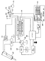
- FIG. 1 is a hydraulic circuit diagram of a heavy construction equipment related to the present invention
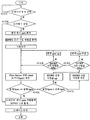
- FIG. 2 is a control flow diagram of one embodiment of the present invention.
- FIG. 1 is a hydraulic circuit diagram of a heavy construction equipment to which the present invention relates
- FIG. 2 is a control flowchart of an embodiment of the present invention.
- the heavy construction equipment according to the embodiment of the present invention, the engine 105, the pump 106 for supplying hydraulic fluid to each work device, such as the breaker 107 using the power provided from the engine and By adjusting the inclination angle of the swash plate of the pump on the basis of various feedback signals such as the flow control signal Pi and the main control valve 108 to control the flow of the hydraulic fluid to selectively supply the hydraulic oil supplied from the pump to each work device
- the pump regulator 101 for controlling the discharge flow rate of the pump 106, and the controller 104 for controlling the rotational speed of the engine and various electrical appliances.
- Such heavy construction equipment can be used by additionally mounting a special work device, and the breaker 107 is also an example of such a special work device.
- the breaker 107 is mounted to the equipment to be driven using the hydraulic oil discharged from the pump 106 at the operator's choice.
- the flow control signal Pi may be configured in various forms according to the type of the pump 106 and the pump regulator 101. In this embodiment, the hydraulic signal generated at a specific signal source and applied to the pump regulator 101 is presented. When the pump regulator 101 is implemented electronically, the flow control signal may be configured as an electronic signal.
- the breaker strike control device of the heavy construction equipment includes a first setting means 109 that allows the driver to input the number of strikes of the breaker, a second setting means 110 that can set the drive environment of the breaker in more detail, And a discharge flow rate adjusting means 120 for adjusting a pump discharge flow rate by adjusting a signal flowing into the pump regulator, wherein the first and second setting means 109 and 110 and the discharge flow rate adjusting means 120 are both It is connected to the controller 104. Accordingly, the controller 104 may control the rotation speed of the engine based on the input signal, and control the discharge flow rate of the pump 106 through the pump regulator control. The controller 104 is also connected with an engine sensor to feedback control the control of the engine speed.
- the discharge flow rate adjusting means 120 includes a subsidiary pump 121 for discharging the auxiliary hydraulic oil and a shuttle valve for providing the pump regulator 101 with hydraulic oil having a large pressure among the auxiliary hydraulic oil and the flow control signal Pi. And a flow rate control valve 103 for regulating the flow rate of the auxiliary hydraulic oil supplied to the shuttle valve 122. If the discharge flow rate of the pump 106 is set through the first setting means 109 or the second setting means 110 that can set the blow frequency (bpm) of the breaker, the flow rate regulating valve 103 corresponds to a proportion corresponding thereto.
- the control signal that is, the EPPRV current command value is received from the controller 104.
- the auxiliary hydraulic oil is applied to the shuttle valve 103 at a flow rate corresponding to the proportional control signal described above, and the applied auxiliary hydraulic oil is supplied to the pump regulator 101 to adjust the discharge flow rate of the pump 106.
- the entire hydraulic system of the heavy equipment is constructed as a negative control system, so that the flow rate of the flow control signal Pi is very small when the breaker 107 is used.
- the discharge flow rate of the pump is controlled by the auxiliary hydraulic oil.
- the pump regulator 101 can be controlled by a proportional control signal output from the controller 104, in which case the controller 104 controls the discharge flow rate It is also possible to perform the function of the means 120.
- FIGS. 1 and 2 a method of controlling a breaker strike of heavy construction equipment according to an embodiment of the present invention will be described with reference to FIGS. 1 and 2.
- the operator When the breaker is used, the operator operates the first setting means or the second setting means which are installed electronically or mechanically in the cab to set the number of blows of the breaker 107.
- the controller 104 controls the engine to be driven at a predetermined engine optimum RPM corresponding to the set number of strikes.
- the pump 106 controls to discharge the optimum flow rate.
- the optimum engine RPM and the optimum pump discharge flow rate are preferably based on data set by the breaker manufacturer in the market.
- the optimal proportional control signal is preferably set to the middle of the range of the proportional control signal that can be output at the engine RPM.
- the controller 104 hits the breaker and checks whether the breaker is driven by the number of hits set by the driver.
- the confirmation of the actual number of hits can be directly counted by the driver, it can be counted by mounting a separate sensor to the breaker or heavy equipment. In this embodiment, the number of blows of the breaker is counted using a flow sensor (not shown).
- the driver determines that the number of hits (set bpm) selected by the driver and the actual number of brakes (actual bpm) are the same, prepare the breaker to be driven by the engine RPM and discharge flow rate used in the test hit.
- the engine speed and the discharge flow rate may be automatically set by the controller 104 so that the changed hit frequency is based on the initially set value.
- it may be configured to re-run the trial hit and the accompanying work at each reset.
- the controller 104 first checks whether the actual number of hits is greater or less than the set hit number. If the actual number of blows is large, the flow rate of the hydraulic oil provided to the breaker is too large than necessary, so the controller raises the proportional control signal, that is, the EPPRV current command value, to increase the breaker supply flow rate. On the contrary, if the actual number of blows is small, the controller reduces the EPPRV current command value because the amount of hydraulic oil supplied to the breaker is too small.
- the fluctuation range of the EPPRV current command value is calculated by the controller, which may occur when the calculated fluctuation range exceeds the limit range, that is, the maximum / lowest EPPRV current command value range.
- the controller raises / lowers the engine RPM so that the discharge flow rate of the pump is controlled to the optimum EPPRV current command value corresponding to the engine RPM.
- the controller 104 rotates the engine 105 at 1800 rpm, which is the number of revolutions corresponding to the optimum fuel economy, to determine the flow rate, and the pump 106. While adjusting the swash plate angle, a signal applied from a flow switch is detected to calculate the number of blows, and 250 lpm, a flow rate corresponding to the number of blows and the set value, is discharged.
- the present invention can be used in the breaker blow control device and control method of the heavy construction equipment that can be set to the number of blows can be set to the number of blows intuitive operation to the operator.
Landscapes
- Engineering & Computer Science (AREA)
- Mining & Mineral Resources (AREA)
- Civil Engineering (AREA)
- Structural Engineering (AREA)
- General Engineering & Computer Science (AREA)
- Mechanical Engineering (AREA)
- Life Sciences & Earth Sciences (AREA)
- Geology (AREA)
- Geochemistry & Mineralogy (AREA)
- General Life Sciences & Earth Sciences (AREA)
- Physics & Mathematics (AREA)
- Fluid Mechanics (AREA)
- Operation Control Of Excavators (AREA)
- Control Of Vehicle Engines Or Engines For Specific Uses (AREA)
Abstract
본 발명의 건설중장비의 브레이커 타격 제어 방법은 펌프 레귤레이터 및 플로우 스위치, 전자비례감압밸브(EPPRV)가 접속되는 콘트롤러를 통해 엔진 및 펌프가 제어되고, 브레이커가 메인 콘트롤 밸브를 통해 펌프에 접속되는 건설중장비의 브레이커 타격 제어 방법을 구성함에 있어서, 작업자에 의해 브레이커 동작이 선택되고, 브레이커 타격횟수가 설정되면 콘트롤러가 최적의 연비구간에 대응되는 회전수로 엔진을 작동시키는 단계와; 콘트롤러가 펌프의 사판각을 조절하여 설정 타격횟수가 나오는 유량이 토출되도록 하는 단계와; 브레이커가 설정 타격횟수만큼 타격되는 단계;를 포함하는 것이다.
Description
본 발명은 건설중장비의 브레이커 타격 제어 장치 및 제어 방법에 관한 것으로, 더 자세하게는 브레이커(Breaker)의 설정을 타격횟수로 설정할 수 있어 작업자에게 직관적인 동작 설정이 가능하도록 한 것에 관한 것이다.
일반적으로 유압 굴삭기를 비롯한 건설중장비는 브레이커(Breaker)의 사용이 가능하다. 상기 브레이커는 대상물을 타격하여 파쇄시키는 장비이다. 이러한 브레이커를 이용한 작업 속도는 브레이커 타격횟수를 설정을 통해 제어가 가능하지만 현재까지는 별도로 브레이커의 타격횟수를 설정하는 기술이 제공되지 않았다. 이에 따라, 브레이커 작업의 제어는 엔진 회전 속도와 토출 유량 설정을 통해 이루어지는 것이 일반적이다. 별도로 브레이커의 타격횟수를 설정하는 기술은 제공되지 않았다.
상기 엔진 회전 속도 설정은 운전실에 마련된 엔진 회전수 조절 스위치 조작을 통해 할 수 있으며, 토출 유량 설정은 계기판 등에 별도로 마련된 입력장치를 통하거나 기 설정된 엔진 회전수에 맞추어 자동으로 설정될 수 있다. 이때 브레이커 타격수와 엔진 회전속도 및 토출 유량의 상관 관계는 브레이커 제조업체에서 제공한 매뉴얼 등을 참조할 수 있다. 하지만 상술한 자료의 브레이커 타격횟수는 별도의 장비를 통해 측정된 브레이커 타격 횟수와 해당 측정시 투입된 유량을 기준으로 인위적으로 계산한 자료이다. 따라서, 브레이커의 타격횟수를 설정하기 위해서는 운전자가 상기 엔진 회전 속도 및/또는 토출 유량을 개략적으로 설정하고 실제 브레이커가 원하는 타격횟수로 작동하는지 확인해야 하는 번거로움이 있다. 원하는 타격횟수로 브레이커가 작동되지 않을 경우에는, 운전자가 개략적으로 엔진 회전 속도 및/또는 토출 유량을 재설정한 후 실제 구동되는 브레이커를 재확인하는 번거로운 작업을 다시 해야 한다. 또한 숙련되지 못한 운전자가 브레이커 타격횟수를 설정할 경우에는 연비 효율이 좋지 않은 영역에서 브레이커가 작동되도록 설정하거나, 브레이커가 허용하는 유량 이상으로 토출 유량을 설정하는 등의 문제가 발생될 수 있다. 이러한 실수는 브레이커의 내구성을 저하시키고, 작업효율도 나쁘게 하는 문제가 발생된다.
본 발명은 상기와 같은 종래의 실정을 감안하여 안출한 것이며, 그 목적이 브레이커의 이용시 연비 효율이 가장 좋은 엔진 회전 속도 영역으로 엔진을 동작시킴으로써 엔진 및 펌프의 최적 제어를 수행할 수 있도록 하는 건설중장비의 브레이커 타격 제어 장치 및 제어방법을 제공하는 데에 있는 것이다.
아울러 본 발명은 그 다른 목적이 보다 정밀하게 브레이커 타격횟수를 설정할 수 있도록 하고, 소비되는 유량을 줄여 연비 저감을 도모할 수 있도록 하며, 규정된 타격횟수를 오버해서 작업하는 것으로 방지할 수 있도록 하는 건설중장비의 브레이커 타격 제어 장치 및 제어방법을 제공하는 데에 있는 것이다.
상기의 목적을 달성하기 위한 본 발명의 건설중장비의 브레이커 타격 제어 방법은 펌프 레귤레이터 및 플로우 스위치, 전자비례감압밸브(EPPRV)가 접속되는 콘트롤러를 통해 엔진 및 펌프가 제어되고, 브레이커가 메인 콘트롤 밸브를 통해 펌프에 접속되는 건설중장비의 브레이커 타격 제어 방법을 구성함에 있어서, 작업자에 의해 브레이커 동작이 선택되고, 브레이커 타격횟수가 설정되면 콘트롤러가 최적의 연비구간에 대응되는 회전수로 엔진을 작동시키는 단계와; 콘트롤러가 펌프의 사판각을 조절하여 설정 타격횟수가 나오는 유량이 토출되도록 하는 단계와; 브레이커가 설정 타격횟수만큼 타격되는 단계;를 포함하는 것이다.
본 발명의 건설중장비의 브레이커 타격 제어 방법에 있어서 상기 콘트롤러가 펌프의 사판각을 조절하여 설정된 타격횟수가 나오는 유량이 토출되도록 하는 단계는, 엔진이 최적 회전수로 작동되면 전자비례감압밸브(EPPRV)의 중간 지령값이 출력되는 단계와; 브레이커를 시험 타격하는 단계와; 플로우 센서 신호를 확인하여 타격횟수를 계산하는 단계와; 설정 타격횟수와 계산 타격횟수가 동일하면 브레이커 엔진 회전수 지령값 및 비례감압밸브(EPPRV) 전류 지령값이 출력되는 단계;를 포함한다.
아울러 설정 타격횟수가 계산 타격횟수 미만이면 비례감압밸브(EPPRV) 전류 지령값을 높이고, 설정 타격횟수가 계산 타격횟수 이상이면 비례감압밸브(EPPRV) 전류 지령값을 낮추는 단계와; 비례감압밸브 전류 지령값이 최대이면 엔진 회전수를 낮추고 비례감압밸브 전류 지령값이 최소이면 엔진 회전수를 높인 후 다시 플로우 센서 신호를 확인하여 타격횟수를 계산하는 단계;를 더 포함한다.
본 발명의 건설중장비의 브레이커 타격 제어 장치 및 방법에 의하면 보다 정밀하게 브레이커 타격횟수를 설정할 수 있게 되고, 소비되는 유량을 줄일 수 있게 되어 연비 저감에 기여할 수 있게 되며, 작업자의 부주의로 인해서 규정된 타격횟수를 오버해서 작업하는 것으로 방지할 수 있게 되므로 건설중장비의 내구성 향상에 크게 기여할 수 있게 되는 등의 효과를 얻을 수 있게 된다.
도 1은 본 발명이 관계하는 건설중장비의 유압 회로도
도 2는 본 발명의 한 실시예의 제어 흐름도
* 도면의 참조 부호 *
101 : 펌프 레귤레이터
102 : 플로우 스위치
103 : 유량조정밸브
104 : 콘트롤러
105 : 엔진
106 : 펌프
107 : 브레이커
108 : 메인 콘트롤 밸브
이하 상기의 목적을 달성하기 위한 본 발명의 구체적인 기술 내용을 첨부도면에 의거하여 자세히 설명하면 다음과 같다.
도 1에는 본 발명이 관계하는 건설중장비의 유압 회로도가 도시되어 있고, 도 2에는 본 발명의 한 실시예의 제어 흐름도가 도시되어 있다.
도 1 및 도 2와 같이 본 발명의 실시예에 따른 건설중장비는, 엔진(105)과, 엔진으로부터 제공된 동력을 이용하여 작동유를 브레이커(107) 등의 각 작업장치에 공급하는 펌프(106)와, 펌프로부터 공급되는 작동유를 각 작업장치에 선택적으로 공급하도록 작동유 흐름을 제어하는 메인 콘트롤 밸브(108)와, 플로우 콘트롤 시그날(Pi) 등의 각종 피드백 신호를 기초로 펌프의 사판의 경사각을 조절함으로써 펌프(106)의 토출 유량을 제어하는 펌프 레귤레이터(101)와, 엔진의 회전수 조절 및 각종 전장품들을 제어하는 콘트롤러(104)를 포함한다. 이러한 건설중장비는 특수 작업 장치를 추가로 장착하여 사용이 가능하며, 브레이커(107) 역시 그러한 특수 작업장치의 일례이다. 브레이커(107)는 작업자의 선택에 따라 펌프(106)로부터 토출되는 작동유를 이용하여 구동될 수 있도록 장비에 장착된다. 여기서 플로우 콘트롤 시그날(Pi)은 펌프(106) 및 펌프 레귤레이터(101)의 종류에 따라 다양한 형태로 구성이 가능하다. 본 실시예에서는 특정 신호 발생원에서 발생되어 펌프 레귤레이터(101)에 인가되는 유압신호로 제시되어 있다. 펌프 레귤레이터(101)이 전자식으로 구현된 경우 플로우 콘트롤 신호는 전자 신호로 구성이 가능하다.
한편, 건설중장비의 브레이커 타격 제어 장치는 운전자가 브레이커의 타격횟수를 입력할 수 있는 제 1 설정수단(109)과, 브레이커의 구동 환경을 보다 상세하게 설정할 수 있는 제 2 설정수단(110)과, 펌프 레귤레이터로 유입되는 신호를 조절하여 펌프 토출 유량을 조절하기 위한 토출 유량 조절 수단(120)을 포함하며, 상기 제1 및 제 2 설정수단(109, 110)과 토출 유량 조절 수단(120)은 모두 콘트롤러(104)에 연결되어 있다. 이에 따라, 콘트롤러(104)는 입력된 신호를 기초로 엔진의 회전수를 제어하고, 펌프 레귤레이터 제어를 통해 펌프(106)의 토출 유량을 제어할 수 있다. 콘트롤러(104)는 엔진 회전수의 제어를 피드백 제어하기 위해 엔진 센서와도 연결된다.
본 실시예에서의 토출 유량 조절 수단(120)은 보조 작동유를 토출하는 보조 펌프(121)와, 보조 작동유와 플로우 콘트롤 시그날(Pi) 중 압력이 큰 작동유를 펌프 레귤레이터(101)에 제공하는 셔틀밸브(122) 및 셔틀밸브(122)로 공급되는 보조 작동유의 유량을 조절하는 유량 조절 밸브(103)을 구비한다. 유량 조절 밸브(103)는 브레이커의 타격횟수(bpm)를 설정할 수 있는 제 1 설정수단(109) 또는 제 2 설정수단(110)을 통해 펌프(106)의 토출유량이 설정되면, 이에 대응되는 비례제어신호, 즉 EPPRV 전류지령값을 콘트롤러(104)로부터 입력받는다. 상술한 비례제어신호에 대응하는 유량으로 보조 작동유를 셔틀밸브(103)으로 인가하게 되며, 인가된 보조 작동유는 펌프 레귤레이터(101)에 공급되어 펌프(106)의 토출유량을 조절할 수 있게 된다. 본 실시예에서는 건설중장비의 전체 유압시스템이 네가티브 콘트롤(Negative control) 시스템으로 구성되어, 브레이커(107)의 사용시 플로우 콘트롤 시그날(Pi)의 유량이 매우 작다. 따라서, 펌프의 토출 유량은 보조 작동유에 의해 제어된다. 도시되지는 않았지만, 건설중장비의 시스템이 전자식 시스템으로 구성된 경우, 펌프 레귤레이터(101)는 콘트롤러(104)로부터 출력되는 비례제어신호에 의해 제어가 가능하며, 이 경우 콘트롤러(104)가 상기 토출 유량 조절 수단(120)의 기능도 수행할 수 있게 된다.
이하, 도 1 및 도 2를 참조하여 본 발명의 실시예에따른 건설중장비의 브레이커 타격 제어 방법을 설명한다.
작업자는 브레이커 사용시 운전실 내에 전자식 또는 기계식으로 설치된 제 1 설정 수단 또는 제 2 설정 수단을 조작하여 브레이커(107)의 타격횟수를 설정한다. 브레이커(107)의 타격횟수가 설정되면, 콘트롤러(104)는 설정된 타격횟수에 대응하는 기 설정된 엔진 최적 RPM으로 엔진이 구동되도록 제어한다. 아울러, 해당 엔진 RPM 및 설정된 타격횟수에 대응되는 비례제어신호(EPPRV 전류 지령값)를 출력하여 펌프(106)가 최적 유량을 토출할 수 있도록 제어한다. 이러한 최적 엔진 RPM 및 최적 펌프 토출 유량은 브레이커 제조사에서 제품 출시시 설정한 데이터에 근거하는 것이 바람직하다. 이때, 최적 비례제어신호는 해당 엔진 RPM에서 출력될 수 있는 비례제어신호의 범위 중 중간으로 설정되는 것이 바람직하다. 이처럼 연비 효율이 가장 좋은 엔진 회전 속도 영역으로 엔진(105)을 동작시킴으로써 엔진(105) 및 펌프(106)의 최적 제어를 수행할 수 있게 된다.
설정된 타격횟수에 대응하는 최적 엔진 RPM 및 펌프 토출유량이 결정되면, 콘트롤러(104)는 브레이커를 시험타격하여 운전자가 설정한 타격횟수대로 브레이커가 구동되는지 확인한다. 물론, 시험 타격 진행을 운전자에게 확인받는 단계가 더 포함되어 시험 타격 진행에 따른 안전사고를 예방하는 것이 바람직하다. 아울러, 실제 타격횟수의 확인은 운전자가 직접 계수할 수 있고, 별도의 센서를 브레이커 또는 건설중장비에 장착하여 계수할 수 있다. 본 실시예에서는 플로우 센서(미도시)를 이용하여 브레이커의 타격수를 계수한다.
상술한 시험타격이 완료되어, 운전자가 선택한 타격횟수(설정 bpm)와 브레이크 실제 타격횟수(실제 bpm)가 동일한 것이 확인되면, 시험타격에 사용된 엔진 RPM과 토출유량으로 브레이커가 구동될 수 있도록 준비를 완료한다. 참고로, 이후에 운전자가 다른 브레이커 타격횟수를 설정하는 경우, 최초에 설정된 설정값을 기준으로 변경된 타격횟수가 나오도록 엔진 회전수와 토출 유량이 컨트롤러(104)에 의해 자동으로 설정될 수 있다. 이 외에도, 재설정시마다 시험타격과 그에 수반되는 작업을 재진행하도록 구성될 수 있다
한편, 시험 타격 결과. 실제 브레이크 타격횟수가 운전자가 설정한 브레이크 타격횟수와 다른 경우, 콘트롤러(104)는 먼저 실제 타격횟수가 설정 타격횟수보다 크거나 작은지를 확인한다. 실제 타격횟수가 큰 경우, 브레이커에 제공되는 작동유의 유량이 필요이상으로 큰 경우이므로, 콘트롤러는 브레이커 공급 유량이 높아지도록 비례제어신호, 즉 EPPRV 전류 지령값을 상승시킨다. 반대로 실제 타격횟수가 작은 경우, 브레이커에 제공되는 작동유의 유량이 필요이상으로 작은 경우이므로, 콘트롤러는 EPPRV 전류 지령값을 감소시킨다. 이러한 EPPRV 전류 지령값의 변동폭은 콘트롤러에 의해 계산되는데, 산출된 변동폭이 제한범위, 즉 최대/최저 EPPRV 전류지령값 범위를 넘는 경우가 발생될 수 있다. 이렇게 EPPRV 전류지령값 범위보다 산출된 EPPRV 전류지령값 변동폭이 큰 경우, 콘트롤러는 엔진 RPM을 상승/하강시켜 해당 엔진 RPM에 대응되는 최적의 EPPRV 전류지령값으로 펌프의 토출유량이 제어되도록 한다. 상술한 제어신호들의 수정이 완료되면 다시 실제 타격수와 설정 타격수를 비교하고, 그 결과에 대응하여 각 제어신호들을 수정 또는 유지한다.
예를 들어 작업자가 브레이커 타격횟수를 420 bpm으로 설정한 경우 콘트롤러(104)는 유량을 결정하기 위해서 엔진(105)을 최적의 연비구간에 대응되는 회전수인1800 rpm 으로 회전시키고, 펌프(106)의 사판각을 조절하면서 플로우 스위치(Flow switch)로부터 인가되는 신호를 검출하여 타격횟수를 계산하고, 타격횟수와 설정값과 일치하는 유량인 250 lpm이 토출되도록 한다.
상기에서 펌프(106)의 사판각 조절만으로 타격횟수와 대응되는 250 lpm이 토출되지 않고, 그보다 적은 230 lpm 이 토출된다거나 그보다 많은 260 lpm이 토출되는 경우 엔진 회전수를 1850 rpm 으로 높이거나 엔진 회전수를 1770으로 낮추어 타격횟수와 설정값이 일치하는 유량인 250 lpm이 토출될 수 있도록 한다.
이렇게 함으로써 종래와 같이 유량으로 타격횟수를 설정하는 것보다 정밀하게 브레이커 타격횟수를 설정할 수 있게 되고, 설정된 타격횟수에 대응되는 최적 엔진 RPM 및 펌프 토출 유량을 사용할 수 있어 브레이커 사용시 소비되는 에너지를 최적화시킬 수 있어, 결국 건설중장비의 연비를 저감시킬 수 있게 된다.
또한 유량으로 설정시 브레이커의 수동 설정의 부주의로 인해서 규정된 타격횟수를 오버해서 작업하는 것으로 방지할 수 있게 되므로 건설중장비의 내구성 향상에 크게 기여할 수 있게 된다.
이상에서 설명한 본 발명은 전술한 설명에 의해 한정되는 것은 아니고, 본 발명의 기술적 사상을 벗어나지 않는 범위 내에서 여러 가지 치환, 변형 및 변경이 가능함은 본 발명이 속하는 기술분야에서 통상의 지식을 가진 자에게 있어 명백할 것이다.
본 발명은 브레이커의 설정을 타격횟수로 설정할 수 있어 작업자에게 직관적인 동작 설정이 가능한 건설중장비의 브레이커 타격 제어장치 및 제어방법에 이용될 수 있다.
Claims (6)
- 엔진에 의해 구동되는 펌프와, 상기 펌프의 사판각을 조절하여 펌프 토출 유량을 제어함과 아울러 엔진의 회전수를 제어가 가능한 콘트롤러(104)를 포함하며, 브레이커를 상기 펌프에서 토출되는 작동유로 구동 가능한 건설중장비의 브레이크 타격 제어 방법에 있어서,브레이커 동작 및 설정 타격횟수를 선택하는 단계;상기 설정 타격횟수에 대응되는 최적 회전수로 엔진(105)의 회전수를 조정하는 단계;상기 설정 타격횟수에 대응되는 유량이 토출되도록 펌프(106)의 사판각을 조절하고 브레이커(107)의 구동을 시작하는 단계; 를 포함하는 건설중장비의 브레이커 타격 제어 방법.
- 제1항에 있어서,상기 펌프(106)의 사판각 조절은, 앞서 조정된 엔진 회전수로 엔진이 구동될 때 토출 가능한 토출 유량 범위 중 실질적으로 중간 토출유량이 토출되도록 조절되고,상기 브레이커의 구동 시작 단계는,상기 브레이커를 시험 타격하는 단계와;상기 브레이커의 실제 타격횟수를 측정하는 단계와;상기 실제 타격횟수와 설정 타격횟수를 비교하는 단계;를 더 포함하는 것을 특징으로 하는 건설중장비의 브레이커 타격 제어 방법.
- 제 2 항에 있어서,상기 실제 타격횟수와 설정 타격횟수의 비교 단계에서,상기 실제 타격횟수가 큰 경우 상기 펌프의 토출 유량이 작아지도록 상기 사판각을 조절하고,상기 실제 타격횟수가 작은 경우 상기 펌프의 토출 유량이 커지도록 상기 사판각을 조절하는 것을 특징으로 하는 건설중장비의 브레이커 타격 제어 방법.
- 제3항에 있어서,상기 토출유량의 변동폭이 기 설정된 변동범위보다 큰 경우상기 엔진 회전수를 재조정하고, 상기 재조정된 엔진 회전수에 대응되게 기 설정된 토출유량이 토출되도록 펌프의 사판각을 조절하는 것을 특징으로 하는 건설중장비의 브레이커 타격 제어 방법.
- 브레이커를 장착하여 작업 가능한 건설중장비의 브레이커 타격 제어 장치에 있어서,엔진으로부터 동력을 제공받아 작동유를 토출하는 펌프;상기 펌프의 토출유량을 제어하는 펌프 레귤레이터;운전자의 조작에 의해 상기 브레이커의 타격횟수 설정이 가능한 설정수단;상기 설정된 브레이커의 타격횟수에 대응하여 상기 엔진의 회전수를 제어함과 아울러 상기 펌프 레귤레이터를 제어함으로써 상기 브레이커에 공급되는 작동유의 유량을 제어하는 콘트롤러;를 포함하는 것을 특징으로 하는 건설중장비의 브레이커 타격 제어 장치.
- 제 5 항에 있어서,상기 콘트롤러는,상기 브레이커의 타격횟수 설정이 완료되면 상기 브레이커를 시험 타격시켜 상기 설정된 타격횟수와 상기 실제 타격횟수를 비교하고, 상기 비교 결과 상기 실제 타격횟수가 큰 경우 상기 펌프의 토출유량이 감소되도록 상기 엔진 및 상기 펌프 레귤레이터 중 적어도 어느 하나를 제어하고, 상기 비교 결과 상기 실제 타격횟수가 작은 경우 상기 펌프의 토출유량이 증가되도록 상기 엔진 및 상기 펌프 레귤레이터 중 적어도 어느 하나를 제어하는 것을 특징으로 하는 건설중장비의 브레이커 타격 제어 장치.
Applications Claiming Priority (2)
| Application Number | Priority Date | Filing Date | Title |
|---|---|---|---|
| KR1020100133281A KR101712675B1 (ko) | 2010-12-23 | 2010-12-23 | 건설중장비의 브레이커 타격 제어 방법 |
| KR10-2010-0133281 | 2010-12-23 |
Publications (2)
| Publication Number | Publication Date |
|---|---|
| WO2012087050A2 true WO2012087050A2 (ko) | 2012-06-28 |
| WO2012087050A3 WO2012087050A3 (ko) | 2012-10-04 |
Family
ID=46314651
Family Applications (1)
| Application Number | Title | Priority Date | Filing Date |
|---|---|---|---|
| PCT/KR2011/010003 Ceased WO2012087050A2 (ko) | 2010-12-23 | 2011-12-22 | 건설중장비의 브레이커 타격 제어 장치 및 제어 방법 |
Country Status (2)
| Country | Link |
|---|---|
| KR (1) | KR101712675B1 (ko) |
| WO (1) | WO2012087050A2 (ko) |
Cited By (1)
| Publication number | Priority date | Publication date | Assignee | Title |
|---|---|---|---|---|
| RU2818883C2 (ru) * | 2021-06-30 | 2024-05-06 | Сани Хэви Машинери Лимитед | Способ управления ударом дробильного молота, устройство, рабочая техника и носитель данных |
Families Citing this family (1)
| Publication number | Priority date | Publication date | Assignee | Title |
|---|---|---|---|---|
| KR101353085B1 (ko) * | 2012-09-24 | 2014-01-20 | (주)한뫼테크 | 브레이커 테스트 장치 |
Family Cites Families (3)
| Publication number | Priority date | Publication date | Assignee | Title |
|---|---|---|---|---|
| JP3064574B2 (ja) * | 1991-09-27 | 2000-07-12 | 株式会社小松製作所 | 油圧掘削機における作業油量切換制御装置 |
| JPH0633905A (ja) * | 1992-07-17 | 1994-02-08 | Yutani Heavy Ind Ltd | 特殊作業機用油圧回路 |
| JPH0868076A (ja) * | 1994-08-29 | 1996-03-12 | Hitachi Constr Mach Co Ltd | 油圧ショベルのブレーカ制御装置 |
-
2010
- 2010-12-23 KR KR1020100133281A patent/KR101712675B1/ko active Active
-
2011
- 2011-12-22 WO PCT/KR2011/010003 patent/WO2012087050A2/ko not_active Ceased
Cited By (1)
| Publication number | Priority date | Publication date | Assignee | Title |
|---|---|---|---|---|
| RU2818883C2 (ru) * | 2021-06-30 | 2024-05-06 | Сани Хэви Машинери Лимитед | Способ управления ударом дробильного молота, устройство, рабочая техника и носитель данных |
Also Published As
| Publication number | Publication date |
|---|---|
| KR20120071650A (ko) | 2012-07-03 |
| KR101712675B1 (ko) | 2017-03-06 |
| WO2012087050A3 (ko) | 2012-10-04 |
Similar Documents
| Publication | Publication Date | Title |
|---|---|---|
| US9206798B2 (en) | Hydraulic pump control apparatus and method of construction machine | |
| EP2518222B1 (en) | Power control apparatus for a construction machine | |
| EP2667060A1 (en) | Wheel rotor and method for controlling wheel rotor | |
| CN101313155B (zh) | 液压作业机械的泵轮力矩控制装置 | |
| US20130125537A1 (en) | Swirl flow control system for construction equipment and method of controlling the same | |
| EP1835079B1 (en) | Electromechanically controlled excavator and method for controlling the electromechanically controlled excavator. | |
| RU2011128301A (ru) | Система для управления гидравлической системой | |
| KR20150122959A (ko) | 건설기계의 엔진 및 유압펌프 통합 제어 장치 및 방법 | |
| EP2657534B1 (en) | Method for controlling hydraulic pump in excavator | |
| US9347467B2 (en) | Method for controlling flow rate of attachment for construction equipment | |
| WO2012087050A2 (ko) | 건설중장비의 브레이커 타격 제어 장치 및 제어 방법 | |
| JP7114302B2 (ja) | ショベル及びショベルの管理装置 | |
| JP2008180203A (ja) | 制御装置 | |
| EP2985391A1 (en) | Apparatus and method for variably controlling spool displacement of construction machine | |
| KR101275012B1 (ko) | 굴삭기용 유량분배 제어장치 및 제어방법 | |
| JPH10237905A (ja) | 建設機械 | |
| JP3947302B2 (ja) | 施工機の掘削制御装置 | |
| KR101762952B1 (ko) | 건설기계의 유압시스템 | |
| JP2004074331A (ja) | ブレーカ用作動油供給制御システム及び供給制御方法 | |
| JP2002030883A (ja) | 施工機の制御装置 | |
| KR20120086061A (ko) | 건설기계의 유압 시스템 | |
| US20170350096A1 (en) | Hydraulic pump control apparatus for construction equipment and control method thereof | |
| KR101220675B1 (ko) | 휠 굴삭기에서의 가속페달을 이용한 엔진 회전수 및 펌프제어장치 | |
| KR20120085598A (ko) | 건설기계의 선회 조작을 위한 전자유압펌프 제어 방법 | |
| JP2000297762A (ja) | 油圧ポンプの出力制御装置 |
Legal Events
| Date | Code | Title | Description |
|---|---|---|---|
| 121 | Ep: the epo has been informed by wipo that ep was designated in this application |
Ref document number: 11851984 Country of ref document: EP Kind code of ref document: A2 |
|
| NENP | Non-entry into the national phase |
Ref country code: DE |
|
| 122 | Ep: pct application non-entry in european phase |
Ref document number: 11851984 Country of ref document: EP Kind code of ref document: A2 |