WO2012086436A1 - 通信装置および通信方法 - Google Patents
通信装置および通信方法 Download PDFInfo
- Publication number
- WO2012086436A1 WO2012086436A1 PCT/JP2011/078550 JP2011078550W WO2012086436A1 WO 2012086436 A1 WO2012086436 A1 WO 2012086436A1 JP 2011078550 W JP2011078550 W JP 2011078550W WO 2012086436 A1 WO2012086436 A1 WO 2012086436A1
- Authority
- WO
- WIPO (PCT)
- Prior art keywords
- level
- communication
- interference
- noise ratio
- communication level
- Prior art date
- Legal status (The legal status is an assumption and is not a legal conclusion. Google has not performed a legal analysis and makes no representation as to the accuracy of the status listed.)
- Ceased
Links
Images






Classifications
-
- H—ELECTRICITY
- H04—ELECTRIC COMMUNICATION TECHNIQUE
- H04L—TRANSMISSION OF DIGITAL INFORMATION, e.g. TELEGRAPHIC COMMUNICATION
- H04L1/00—Arrangements for detecting or preventing errors in the information received
- H04L1/0001—Systems modifying transmission characteristics according to link quality, e.g. power backoff
-
- H—ELECTRICITY
- H04—ELECTRIC COMMUNICATION TECHNIQUE
- H04L—TRANSMISSION OF DIGITAL INFORMATION, e.g. TELEGRAPHIC COMMUNICATION
- H04L1/00—Arrangements for detecting or preventing errors in the information received
- H04L1/0001—Systems modifying transmission characteristics according to link quality, e.g. power backoff
- H04L1/0015—Systems modifying transmission characteristics according to link quality, e.g. power backoff characterised by the adaptation strategy
- H04L1/0016—Systems modifying transmission characteristics according to link quality, e.g. power backoff characterised by the adaptation strategy involving special memory structures, e.g. look-up tables
-
- H—ELECTRICITY
- H04—ELECTRIC COMMUNICATION TECHNIQUE
- H04L—TRANSMISSION OF DIGITAL INFORMATION, e.g. TELEGRAPHIC COMMUNICATION
- H04L27/00—Modulated-carrier systems
- H04L27/0008—Modulated-carrier systems arrangements for allowing a transmitter or receiver to use more than one type of modulation
-
- H—ELECTRICITY
- H04—ELECTRIC COMMUNICATION TECHNIQUE
- H04L—TRANSMISSION OF DIGITAL INFORMATION, e.g. TELEGRAPHIC COMMUNICATION
- H04L1/00—Arrangements for detecting or preventing errors in the information received
- H04L1/0001—Systems modifying transmission characteristics according to link quality, e.g. power backoff
- H04L1/0002—Systems modifying transmission characteristics according to link quality, e.g. power backoff by adapting the transmission rate
- H04L1/0003—Systems modifying transmission characteristics according to link quality, e.g. power backoff by adapting the transmission rate by switching between different modulation schemes
Definitions
- the present invention relates to a communication device and a communication method.
- Adaptive modulation switching control that uses the most appropriate modulation method according to the situation in systems that aim to improve frequency utilization efficiency such as WiMAX (Worldwide Interoperability for Microwave Access), LTE (Long Term Evolution), XGP (eXtended Global Platform), etc. Is used.
- WiMAX Worldwide Interoperability for Microwave Access
- LTE Long Term Evolution
- XGP Extended Global Platform
- modulation mode switching is generally determined using an error rate. Specifically, if an error does not occur in the currently used modulation method, the modulation method is switched to a higher modulation method (see, for example, Patent Document 1 (Japanese Patent Laid-Open No. 2010-219949)).
- MCS Modulation and Coding Scheme
- the error rate may be 100% in a higher modulation scheme B. Therefore, in the modulation scheme A, when switching to the modulation scheme B based on the error rate (0%), the throughput decreases.
- an object of the present invention is to provide a communication device and a communication method capable of switching the modulation method without reducing the throughput.
- the communication apparatus of the present invention is information that defines correspondence between a communication level determined by at least a modulation method and a coding rate and a range of required carrier level to interference / noise ratio at the communication level.
- the communication quality management unit for acquiring the carrier level to interference / noise ratio of the received signal in the other communication device of the communication partner.
- the difference between the typical value of the required carrier level-to-interference / noise ratio range at the communication level and the typical value of the required carrier level-to-interference / noise ratio range of the higher-level communication level is A setting unit that sets a communication level such that the carrier level-to-interference / noise ratio of the acquired received signal is within the range of the required carrier level-to-interference / noise ratio when the received signal is equal to or greater than the threshold;
- a transmitter for transmitting the Flip signal.
- the modulation method can be switched without lowering the throughput.
- FIG. 1 is a diagram illustrating a configuration of a radio base station according to the first embodiment.
- this radio base station 2 is a base station that operates in a WiMAX communication system, and includes a first antenna 10, a second antenna 11, a transmission unit 13, a reception unit 12, and the like. And a MAC (Media Access Control) layer processing unit 14.
- MAC Media Access Control
- the transmission unit 13 includes a multi-antenna transmission signal processing unit 24, a subcarrier arrangement unit 23, an IFFT unit (Inverse First Fourier Transform) 22, a CP (Cyclic Prefix) addition unit 21, an RF (Radio Frequency) unit 20, Is provided.
- IFFT unit Inverse First Fourier Transform
- CP Cyclic Prefix
- RF Radio Frequency
- the subcarrier arrangement unit 23 arranges subcarriers based on, for example, PUSC (Partial Usage of Subchannels).
- the multi-antenna transmission signal processing unit 24 transmits a signal by a MIMO communication method that is a wireless communication method that extends a data transmission / reception band by combining a plurality of antennas.
- a MIMO (Multiple Input Multiple Output) communication method hereinafter referred to as a DL-MIMO (DownLink-MIMO) communication method set for a downlink signal is defined by the WiMAX forum.
- one data stream is space-time coded (for example, Aramuch coding)
- a plurality of data streams are spatially multiplexed.
- the IFFT unit 22 converts the plurality of subcarrier signals (frequency domain signals) output from the multi-antenna transmission signal processing unit 24 into time domain signals (OFDMA (Orthogonal Frequency Division Multiple Access) symbols) by IFFT.
- OFDMA Orthogonal Frequency Division Multiple Access
- the CP adding unit 21 adds the same signal as the tail part of the OFDMA symbol to the beginning of the OFDMA symbol as a CP.
- the RF unit 20 includes an up-converter that up-converts to a radio frequency band, a power amplification circuit that amplifies the up-converted signal, and passes only the signal component in the desired band of the amplified signal to pass through the first antenna 10 and the first antenna 10.
- a band-pass filter that outputs to the second antenna 11.
- the receiving unit 12 includes an RF unit 15, a CP removing unit 16, an FFT unit 17, and a subcarrier arrangement unit 18.
- the RF unit 15 includes a band-pass filter that allows only a signal component in a desired band among signals output from the first antenna 10 and the second antenna 11 to pass, a low-noise amplifier circuit that amplifies the RF signal, and the RF signal that is down Includes down coater to convert.
- the CP removal unit 16 removes the CP from the signal output from the RF unit 15.
- the FFT unit 17 converts the time domain signal output from the CP removal unit 16 into a frequency domain signal by FFT and demodulates the signal into a plurality of subcarriers.
- the subcarrier arrangement unit 18 extracts each subcarrier output from the FFT unit 17 based on PUSC, for example.
- the MAC layer processing unit 14 includes a user data transmission management unit 34, an encoding unit 33, a modulation unit 32, a demodulation unit 25, a decoding unit 26, a user data reception management unit 27, and a control unit 41. .
- the user data transmission management unit 34 manages user data transmitted to the wireless terminal.
- the encoding unit 33 encodes the downlink signal according to the encoding rate of MCS (Modulation and Code Scheme) indicated by the setting unit 46.
- MCS defines a modulation scheme (QPSK, 16QAM, 64AQAM, etc.) and coding rate (1/2, 2/3, 3/4).
- the modulation unit 32 modulates the encoded downlink signal to the wireless terminal in accordance with the MCS modulation method instructed from the setting unit 46.
- the demodulator 25 demodulates the uplink signal from the wireless terminal.
- the decoding unit 26 decodes the demodulated uplink signal.
- the user data reception management unit 27 manages user data received from the wireless terminal.
- the control unit 41 includes a communication level table storage unit 42, a communication quality management unit 44, a setting unit 46, and a switching notification unit 45.
- the communication quality management unit 44 periodically receives the PER (Packet Error Rate) of the received signal (that is, the downlink signal) from the wireless terminal of the communication partner and the CINR (Carrier of the downlink signal). to Interference and Noise Ratio), or information that can replace them.
- PER Packet Error Rate
- CINR Carrier of the downlink signal. to Interference and Noise Ratio
- PER represents a certain percentage of packets with errors in received packets.
- CINR is represented by a value obtained by dividing carrier power by the sum of interference signal power and noise power.
- the communication level table storage unit 42 stores a communication level table that defines the correspondence between the communication level and the range of the required CINR at the communication level.
- the communication level is a value determined by the MIMO communication method and the MCS. With the same PER, the higher the communication level, the higher the throughput.
- the range of the required CINR is calculated from theoretical values, simulations, actual measurement results, or the like.
- FIG. 2 is a diagram illustrating an example of a communication level table.
- the communication level is determined by the DL-MIMO communication method and MCS.
- the DL-MIMO communication method is “MATRIX-A”
- the MCS is “QPSK 1/2”
- the required CINR range is x1 [dB] or less.
- the DL-MIMO communication method is “MATRIX-B”
- the MCS is “64QAM 2/3”
- the required CINR range exceeds x8 [dB]
- x9 [dB] The range is as follows.
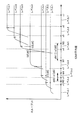
- FIG. 3 is a diagram illustrating an experimental result of a relationship between the CINR of the downlink signal and the throughput of the downlink signal for each communication level.
- the throughput represents a value obtained by subtracting a loss due to error correction, a protocol overhead, and the like from a theoretically realizable data transfer amount per unit time (theoretical throughput).
- the communication level is switched according to the CINR value according to the communication level table of FIG.
- the current communication level is “2”, that is, when the DL-MIMO communication method is MATRIX-A and the MCS is QPSK 3/4, as shown in FIG.
- the maximum throughput is obtained and an error free state is obtained.
- the error-free state is a state where the error is almost 0%.
- the communication level is increased by one step, that is, when the DL-MIMO communication method is MATRIX-A and the MCS is switched to 16QAM 1/2, the throughput increases as shown in FIG.
- the setting unit 46 switches the communication level while preventing a decrease in throughput that occurs when the communication level is “4” as described above.
- the setting unit 46 lowers the communication level by one step.
- the setting unit 46 represents the representative value (lower limit, median, or upper limit) of the required CINR for the current communication level and the representative value of the required CINR for the communication level one level higher.
- the difference dM from the (lower limit value, median value, or upper limit value) is less than ⁇ [dB]
- the communication level is increased by one step.
- Y ⁇ X.
- the reason why X and Y are set to different values is to create a state in which the communication level is maintained. This is because when X and Y are the same, the increase or decrease of the communication level is frequently repeated, and the processing load increases on the transmission side and the reception side.
- the setting unit 46 determines that the difference between the representative value of the required CINR at the current communication level and the representative value of the required CINR at the communication level one level above is ⁇ [dB] or more. In some cases, if the acquired CINR belongs to the required CINR of the current communication level, the current communication level is maintained.
- the setting unit 46 determines that the difference between the representative value of the required CINR at the current communication level and the representative value of the required CINR at the communication level one level above is ⁇ [dB] or more. In some cases, if the acquired CINR does not belong to the range of the required CINR of the current communication level, the communication level in which the acquired CINR is included in the range of the required CINR is selected and changed to the selected communication level.
- the setting unit 46 maintains the current communication level when the acquired PER exceeds Y% and is less than X%.
- the switching notification unit 45 outputs a signal for notifying the MIMO communication method and MCS of the downlink signal to the wireless terminal whose communication level has been switched by the setting unit 46.
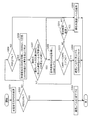
- FIG. 4 is a flowchart showing an operation procedure of the radio base station according to the first embodiment.
- the communication quality management unit 44 acquires the PER of the signal received by the wireless terminal from the wireless terminal (step S101).
- step S102 If the acquired PER is X% or more (YES in step S102), the setting unit 46 lowers the communication level by one step (step S103).
- the setting unit 46 refers to the communication level table and increases the representative value of the required CINR at the current communication level by one level.
- the communication level is increased by one step. For example, as shown in FIG. 3, when the current communication level is “2”, the representative value M3 of the required CINR at the current communication level and the representative value M4 of the required CINR at the communication level “3” one level higher. Since the difference dM2 is less than ⁇ [dB], the setting unit 46 increases the communication level by one level (step S108).
- the communication quality management unit 44 refers to the communication level table and sets the representative value of the required CINR for the current communication level to 1
- the difference between the staged communication level and the representative value of the required CINR is not less than ⁇ [dB] (YES in step S106)
- the CINR of the signal received by the wireless terminal is acquired from the wireless terminal. For example, as shown in FIG.
- the communication quality management unit 44 acquires the CINR of the signal received by the wireless terminal from the wireless terminal (step S107).
- step S109 When the acquired CINR belongs to the required CINR of the current communication level (YES in step S109), the setting unit 46 maintains the current communication level (step S105).
- the setting unit 46 refers to the communication level table and the acquired CINR is included in the required CINR range. Select the communication level and change to the selected communication level. For example, as shown in FIG. 3, when the current communication level is “4” and the acquired CINR is S3 [dB], the acquired CINR is included in the CINR range of the communication level “5”. Then, the communication level is changed to “5” (step S110).
- step S105 When the acquired PER exceeds Y% and is less than X% (NO in step S102, NO in step S104), the setting unit 46 maintains the current communication level (step S105).
- the setting unit 46 switches throughput by preventing a decrease in throughput by a method different from that of the first embodiment.
- the setting unit 46 lowers the communication level by one step.
- the setting unit 46 determines that the difference between the representative value of the required CINR at the current communication level and the representative value of the required CINR at the communication level one level above is less than ⁇ [dB]. In some cases, as described in the first embodiment, even if the communication level is increased, the problem that the throughput decreases is unlikely to occur, so the communication level is increased by one step.
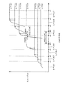
- the setting unit 46 stores the CINR acquired at that time as CINR0. For example, as shown in FIG. 5, it is assumed that CINR0 is stored at time T1.
- the setting unit 46 acquires the CINR at regular intervals, This is designated as CINR1.
- CINR1 the CINR representative value M1 of the current communication level and the required CINR representative value M2 of the communication level “5” one level higher Since the difference dM is ⁇ [dB] or more, the communication quality management unit 44 periodically acquires the CINR of the signal received by the wireless terminal from the wireless terminal for a predetermined period, and sets the acquired CINR as CINR1. .
- the setting unit 46 increases the communication level by one step when the difference between CINR1 and CINR0 becomes equal to or greater than ⁇ [dB]. For example, as shown in FIG. 5, since the difference dC between CINR1 and CINR0 is equal to or greater than ⁇ [dB] at time T2, the setting unit 46 increases the communication level by one level.
- the throughput decreases as shown in FIG.
- the throughput can be increased as shown in FIG. 5 by increasing the communication level only when the difference between CINR1 and CINR0 is equal to or greater than ⁇ and at time T2.
- the setting unit 46 maintains the current communication level when the difference from CINR0 is less than ⁇ [dB].
- the setting unit 46 maintains the current communication level when the acquired PER exceeds Y% and is less than X%.
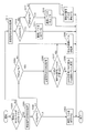
- FIG. 6 is a flowchart showing an operation procedure of the radio base station according to the second embodiment.
- the communication quality management unit 44 acquires the PER of the signal received by the wireless terminal from the wireless terminal (step S201).
- step S203 If the acquired PER is X% or more (YES in step S202), the setting unit 46 lowers the communication level by one step (step S203).
- the communication quality management unit 44 acquires the CINR of the signal received by the wireless terminal from the wireless terminal, and acquires at that time
- the recorded CINR is stored as CINR0, and the value of CINR0 is set to prohibit overwriting (step S206).
- the setting unit 46 refers to the communication level table, and when the difference between the representative value of the required CINR at the current communication level and the representative value of the required CINR at the communication level one level above is less than ⁇ [dB]. (NO in step S207), the communication level is increased by one step, and the value of CINR0 is reset to “0” (step S208).
- the communication quality management unit 44 refers to the communication level table, and when the difference between the representative value of the required CINR at the current communication level and the representative value of the required CINR at the communication level one level above is ⁇ [dB] or more. (YES in step S207)
- the CINR of the signal received by the wireless terminal is acquired from the wireless terminal at regular time intervals, and this is designated as CINR1. For example, as shown in FIG.
- the communication quality management unit 44 acquires the CINR of the signal received by the wireless terminal from the wireless terminal, and sets this as CINR1 (step S209).
- the setting unit 46 increases the communication level by one level and further resets the value of CINR0 to “0”. For example, as illustrated in FIG. 5, when the difference dC between CINR1 and CINR0 is equal to or larger than ⁇ [dB], the setting unit 46 increases the communication level by one level (step S208).
- step S210 When the difference between CINR1 and CINR0 is less than ⁇ [dB] (NO in step S210), setting unit 46 determines that the current communication is performed when a predetermined time has elapsed since step S206 (YES in step S211). The level is maintained (step S205). When the difference between CINR1 and CINR0 is less than ⁇ [dB] (NO in step S210), the setting unit 46 determines that the predetermined time has not elapsed since the process of step S206 (NO in step S211). Return to S209.
- step S205 When the acquired PER exceeds Y% and is less than X% (NO in step S202, NO in step S204), the setting unit 46 maintains the current communication level (step S205).
- the setting unit 46 switches the communication level according to the same standard as in the first embodiment. If the MCS defined by the current communication level is not 16QAM 3/4, the setting unit 46 switches the communication level based on the PER.
- FIG. 7 is a flowchart showing an operation procedure of the radio base station according to the third embodiment.
- the communication quality management unit 44 acquires the PER of the signal received by the wireless terminal from the wireless terminal (step S301).
- step S302 If the acquired PER is X% or more (YES in step S302), the setting unit 46 lowers the communication level by one level (step S303).
- step S305 If the acquired PER is less than X% and exceeds Y% (NO in step S302, NO in step S304), the setting unit 46 maintains the current communication level (step S305).
- the communication quality management unit 44 acquires the CINR of the signal received by the wireless terminal from the wireless terminal. (Step S306).
- the setting unit 46 refers to the communication level table, and if the acquired CINR does not belong to the required CINR range of the current communication level (NO in step S307), the setting unit 46 refers to the communication level table and acquires the acquired CINR. Selects a communication level included in the range of the required CINR, and changes to the selected communication level (step S308).
- the setting unit 46 maintains the current communication level (step S305).
- the communication quality management unit 44 acquires the PER of the signal received by the wireless terminal from the wireless terminal (step S311).
- step S312 If the acquired PER is X% or more (YES in step S312), the setting unit 46 lowers the communication level by one level (step S313).
- step S315 When the acquired PER is Y% or less (NO in step S312 and YES in step S314), the setting unit 46 increases the communication level by one level (step S315).
- step S316 When the acquired PER exceeds Y% and is less than X% (NO in step S312 and NO in step S314), the setting unit 46 maintains the current communication level (step S316).
- FIG. 8 is a diagram illustrating the configuration of a radio base station according to the fourth embodiment of the present invention.
- the required CINR storage unit 142 for 16QAM3 / 4 stores information indicating the range of required CINR when the communication level is 16QAM3 / 4.
- FIG. 9 is a flowchart showing an operation procedure of the radio base station according to the fourth embodiment.
- the communication quality management unit 44 acquires the PER of the signal received by the wireless terminal from the wireless terminal (step S501).
- step S503 If the acquired PER is X% or more (YES in step S502), the setting unit 46 lowers the communication level by one level (step S503).
- step S505 When the acquired PER is less than X% and exceeds Y% (NO in step S502, NO in step S504), the setting unit 46 maintains the current communication level (step S505).
- the communication quality management unit 44 acquires the CINR of the signal received by the wireless terminal from the wireless terminal. (Step S506).
- the setting unit 46 refers to the information in the required CINR storage unit 142 for 16QAM3 / 4, and if the acquired CINR exceeds the range of the required CINR of the current communication level (YES in step S507), the MCS level Is changed to 64QAM 2/3 and the DL-MIMO communication system is maintained (step S508).
- the setting unit 46 refers to the information in the required CINR storage unit 142 for 16QAM3 / 4, and when the acquired CINR does not exceed the range of the required CINR at the current communication level (NO in step S507), The communication level is maintained (step S505).
- the communication quality management unit 44 acquires the PER of the signal received by the wireless terminal from the wireless terminal (step S511).
- step S512 If the acquired PER is X% or more (YES in step S512), the setting unit 46 lowers the communication level by one level (step S513).
- step S512 When the acquired PER is Y% or less (NO in step S512, YES in step S514), the setting unit 46 increases the communication level by one level (step S515).
- step S512 If the acquired PER exceeds Y% and is less than X% (NO in step S512, NO in step S514), the setting unit 46 maintains the current communication level (step S516).
- the setting unit 46 switches the communication level according to the same standard as in the second embodiment. If the MCS defined by the current communication level is not 16QAM 3/4, the setting unit 46 switches the communication level based on the PER.
- FIG. 10 is a flowchart illustrating an operation procedure of the radio base station according to the fifth embodiment.
- the communication quality management unit 44 acquires the PER of the signal received by the wireless terminal from the wireless terminal (step S401).
- step S403 If the acquired PER is X% or more (YES in step S402), the setting unit 46 lowers the communication level by one step (step S403).
- step S405 When the acquired PER is less than X% and exceeds Y% (NO in step S402, NO in step S404), the setting unit 46 maintains the current communication level (step S405).
- the communication quality management unit 44 acquires the CINR of the signal received by the wireless terminal from the wireless terminal.
- the CINR acquired at that time is stored as CINR0, and the value of CINR0 is set to prohibit overwriting (step S406).
- the communication quality management unit 44 acquires the CINR of the signal received by the wireless terminal from the wireless terminal at regular time intervals, and sets this as CINR1 (step S407).
- step S408 If the difference between CINR1 and CINR0 is equal to or greater than ⁇ [dB] (YES in step S408), the setting unit 46 changes the MCS level to 64QAM 2/3, maintains the DL-MIMO communication system, and The value of CINR0 is reset to “0” (step S409).
- step S408 When the difference between CINR1 and CINR0 is less than ⁇ [dB] (NO in step S408), if a predetermined time has elapsed from the processing in step S406 (YES in step S410), the setting unit 46 determines the current communication. The level is maintained (step S405).
- step S408 When the difference between CINR1 and CINR0 is less than ⁇ [dB] (NO in step S408), if the predetermined time has not elapsed since the process of step S406 (NO in step S410), the setting unit 46 Return to S407.
- the communication quality management unit 44 acquires the PER of the signal received by the wireless terminal from the wireless terminal (step S411).
- step S412 If the acquired PER is X% or more (YES in step S412), the setting unit 46 lowers the communication level by one step (step S413).
- the setting unit 46 increases the communication level by one level (step S415).
- step S412 When the acquired PER exceeds Y% and is less than X% (NO in step S412 and NO in step S414), the setting unit 46 maintains the current communication level (step S416).
- the communication level switching method described in the embodiment of the present invention can be applied to another communication system other than WiMAX such as LTE and XGP.
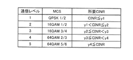
- FIG. 11 is a diagram illustrating an example of a communication level table in another communication system. Referring to FIG. 11, the communication level is determined by MCS.
- the MCS is “QPSK 1/2”, and the range of the required CINR is y1 [dB] or less.
- the communication level is “4”
- the MCS is “64QAM 2/3”
- the required CINR range is greater than y3 [dB] and less than or equal to y4 [dB].
- FIG. 12 is a diagram showing the relationship between CINR and throughput for each communication level in another communication system.
- the communication level is switched according to the CINR value according to the communication level table of FIG.
- the throughput increases when the communication level is increased by one step when the maximum throughput is obtained and the error free state is reached.
- the throughput decreases when the communication level is increased by one step when the maximum throughput is obtained and the error free state is reached.
- the setting unit switches the communication level while preventing a decrease in throughput that occurs when the communication level is “2” or “3” as described above. That is, when the communication level is “2” and “3”, the setting unit performs the processing of steps S301 to S311 in FIG. 7 or the processing of steps S401 to S410 in FIG.
- Predetermined value ⁇ of the second embodiment may be calculated by experimenting CINR0 that is the value of CINR at the time when the error becomes free. For example, ⁇ can be determined as a value that is equal to or greater than the difference between CINR0 and the lower limit of the required CINR range of the communication level one level higher than the current communication level. The value of ⁇ can be set to a different value for each communication level, or can be set to the same value for all communication levels. Further, ⁇ may be a mere predetermined value without using an experiment.
- Radio base station 10, 11 antenna, 12 transmitting unit, 13 receiving unit, 14 MAC layer processing unit, 15, 20 RF unit, 16 CP removing unit, 17 FFT unit, 18, 23 subcarrier placement unit, 21 CP addition Unit, 22 IFFT unit, 24 multi-antenna transmission signal processing unit, 25 demodulation unit, 26 decoding unit, 27 user data reception management unit, 32 modulation unit, 33 encoding unit, 34 user data transmission management unit, 41 control unit, 44 Communication quality management unit, 45 switching notification unit, 46 setting unit, 142 required CINR storage unit for 16QAM3 / 4.
Landscapes
- Engineering & Computer Science (AREA)
- Signal Processing (AREA)
- Computer Networks & Wireless Communication (AREA)
- Quality & Reliability (AREA)
- Mobile Radio Communication Systems (AREA)
Abstract
通信レベルテーブル記憶部(42)は、少なくともMCS(変調方式および符号化レート)で定められる通信レベルと、通信レベルでの所要CINRの範囲との対応を定めた通信レベルテーブルを記憶する。通信品質管理部(44)は、通信相手の他の通信装置での受信信号のCINRを取得する。設定部(46)は、通信レベルテーブルを参照して、現在の通信レベルでの所要CINRの範囲の代表値と一段上の通信レベルのCINRの所要CINRの範囲の代表値との差が閾値以上の場合に、取得した受信信号のCINRが所要CINRの範囲に含まれるような通信レベルを設定する。
Description
本発明は、通信装置および通信方法に関する。
WiMAX(Worldwide Interoperability for Microwave Access)、LTE(Long Term Evolution)、XGP(eXtended Global Platform)などの周波数利用効率の向上を目指したシステムでは、状況に応じて最適な変調方式を使用する適応変調切替制御が使われている。
適応変調切替制御では、一般的に、エラー率を用いて変調方式の切替えを判断する。具体的には、現在使用している変調方式でエラーが発生しなくなれば一段上の変調方式へ切替える(たとえば、特許文献1(特開2010-219949号公報)を参照)。
しかしながら、適応変調に使われるMCS(Modulation and Coding Scheme:変調方式および符号化率)は、システムに応じて様々である。
あるシステムでは、ある変調方式Aでは、エラー率が0%を維持することができる受信状況であっても、一段上の変調方式Bでは、エラー率が100%となる場合がある。したがって、変調方式Aにおいて、エラー率(0%)に基づいて変調方式Bに切替えた場合に、スループットが低下することになる。
それゆえに、本発明の目的は、スループットを低下させることなく、変調方式を切替えることのできる通信装置および通信方法を提供することである。
上記課題を解決するために、本発明の通信装置は、少なくとも変調方式および符号化レートで定められる通信レベルと、通信レベルでの所要搬送波レベル対干渉・雑音比の範囲との対応を定めた情報を記憶する記憶部と、通信相手の他の通信装置での受信信号の搬送波レベル対干渉・雑音比を取得する通信品質管理部と、前記記憶部内の対応を定めた情報を参照して、現在の通信レベルでの所要搬送波レベル対干渉・雑音比の範囲の代表値と一段上の通信レベルの搬送波レベル対干渉・雑音比の所要搬送波レベル対干渉・雑音比の範囲の代表値との差が閾値以上の場合に、取得した受信信号の搬送波レベル対干渉・雑音比が所要搬送波レベル対干渉・雑音比の範囲に含まれるような通信レベルを設定する設定部と、設定された通信レベルに応じた信号を送信する送信部とを備える。
本発明によれば、スループットを低下させることなく、変調方式を切替えることができる。
以下、本発明の実施形態について図面を参照して説明する。
[第1の実施形態]
(無線基地局の構成)
図1は、第1の実施形態の無線基地局の構成を表わす図である。
[第1の実施形態]
(無線基地局の構成)
図1は、第1の実施形態の無線基地局の構成を表わす図である。
図1を参照して、この無線基地局2は、WiMAXの通信方式で動作する基地局であって、第1のアンテナ10と、第2のアンテナ11と、送信部13と、受信部12と、MAC(Media Access Control)層処理部14とを備える。
送信部13は、マルチアンテナ送信信号処理部24と、サブキャリア配置部23と、IFFT部(Inverse First Fourier Transform)22と、CP(Cyclic Prefix)付加部21と、RF(Radio Frequency)部20とを備える。
サブキャリア配置部23は、たとえばPUSC(Partial Usage of Subchannels)に基づいて、サブキャリアを配置する。
マルチアンテナ送信信号処理部24は、複数のアンテナを組み合わせてデータ送受信の帯域を広げる無線通信方式であるMIMO通信方式で、信号を送信する。マルチアンテナ送信信号処理部24は、ダウンリンク信号に設定されたMIMO(Multiple Input Multiple Output)通信方式(以下では、DL-MIMO(DownLink-MIMO)通信方式と呼ぶ)が、WiMAXフォーラムで規定されるMATRIX-Aの場合に、1つのデータストリームを時空間符号化(たとえばアラムーチ符号化)し、DL-MIMO通信方式がWiMAXフォーラムで規定されるMATRIX-Bの場合に、複数のデータストリームを空間多重化する。
IFFT部22は、マルチアンテナ送信信号処理部24から出力される複数のサブキャリア信号(周波数領域の信号)をIFFTによって、時間領域の信号(OFDMA(Orthogonal Frequency Division Multiple Access)シンボル)に変換する。
CP付加部21は、OFDMAシンボルの後尾部分と同じ信号をCPとしてOFDMAシンボルの先頭に付加する。
RF部20は、無線周波数帯にアップコンバートするアップコンバータ、アップコンバートされた信号を増幅する電力増幅回路、増幅された信号のうち所望帯域の信号成分のみを通過させて第1のアンテナ10および第2のアンテナ11へ出力するバンドパスフィルタなどを含む。
受信部12は、RF部15と、CP除去部16と、FFT部17と、サブキャリア配置部18とを備える。
RF部15は、第1のアンテナ10および第2のアンテナ11から出力される信号のうち所望帯域の信号成分のみを通過させるバンドパスフィルタ、RF信号を増幅する低雑音増幅回路、RF信号をダウンコンバートするダウンコータなどを含む。
CP除去部16は、RF部15から出力される信号からCPを除去する。
FFT部17は、CP除去部16から出力される時間領域の信号をFFTによって、周波数領域の信号に変換して、複数のサブキャリアに復調する。
FFT部17は、CP除去部16から出力される時間領域の信号をFFTによって、周波数領域の信号に変換して、複数のサブキャリアに復調する。
サブキャリア配置部18は、たとえばPUSCに基づいて、FFT部17から出力される各サブキャリアを抽出する。
MAC層処理部14は、ユーザデータ送信管理部34と、符号化部33と、変調部32と、復調部25と、復号部26と、ユーザデータ受信管理部27と、制御部41とを含む。
ユーザデータ送信管理部34は、無線端末へ送信するユーザデータを管理する。
符号化部33は、設定部46から指示されるMCS(Modulation and Code Scheme)の符号化レートに従って、ダウンリンク信号を符号化する。MCSは、変調方式(QPSK、16QAM、64AQAMなど)と符号化率(1/2、2/3、3/4)を規定する。
符号化部33は、設定部46から指示されるMCS(Modulation and Code Scheme)の符号化レートに従って、ダウンリンク信号を符号化する。MCSは、変調方式(QPSK、16QAM、64AQAMなど)と符号化率(1/2、2/3、3/4)を規定する。
変調部32は、設定部46から指示されるMCSの変調方式に従って、符号化された無線端末へのダウンリンク信号を変調する。
復調部25は、無線端末からのアップリンク信号を復調する。
復号部26は、復調されたアップリンク信号を復号する。
復号部26は、復調されたアップリンク信号を復号する。
ユーザデータ受信管理部27は、無線端末から受信したユーザデータを管理する。
制御部41は、通信レベルテーブル記憶部42と、通信品質管理部44と、設定部46と、切替通知部45とを含む。
制御部41は、通信レベルテーブル記憶部42と、通信品質管理部44と、設定部46と、切替通知部45とを含む。
通信品質管理部44は、定期的に通信相手の無線端末から、その無線端末での受信信号(つまりダウンリンク信号)のPER(Packet Error Rate:パケットエラーレート)と、ダウンリンク信号のCINR(Carrier to Interference and Noise Ratio:搬送波レベル対干渉・雑音比)、あるいはこれらを代替できる情報の通知を受ける。PERは、受信したパケットのうち、エラーのあるパケットのある割合を表わす。CINRは、搬送波電力を干渉信号電力と雑音電力の和で除算した値で表わされる。
通信レベルテーブル記憶部42は、通信レベルと、通信レベルでの所要CINRの範囲との対応を定めた通信レベルテーブルを記憶する。本明細書では、通信レベルは、MIMO通信方式とMCSによって定まる値とする。同一のPERでは、通信レベルが高いほど、スループットが高くなる。所要CINRの範囲は、理論値、シミュレーション、または実測結果などから算出したものが用いられる。
図2は、通信レベルテーブルの例を表わす図である。
図2を参照して、通信レベルは、DL-MIMO通信方式およびMCSによって定まる。
図2を参照して、通信レベルは、DL-MIMO通信方式およびMCSによって定まる。
たとえば、通信レベルが「1」は、DL-MIMO通信方式が「MATRIX-A」であり、MCSが「QPSK 1/2」であり、所要CINRの範囲はx1[dB]以下である。
通信レベルが「9」は、DL-MIMO通信方式が「MATRIX-B」であり、MCSが「64QAM 2/3」であり、所要CINRの範囲はx8[dB]を越え、かつx9[dB]以下の範囲である。
通信レベルの値を増加する場合に、本明細書では、「通信レベルを上げる(増加させる)」と記載し、通信レベルの値を減少する場合に、本明細書では、「通信レベルを下げる(減少させる)」と記載する。
(スループット特性)
図3は、通信レベルごとのダウンリンク信号のCINRとダウンリンク信号のスループットの関係の実験結果を表わす図である。スループットは、理論上実現可能な単位時間あたりのデータ転送量(理論スループット)から、エラー訂正による損失、およびプロトコルのオーバーヘッドなどを差し引いた値を表わす。
図3は、通信レベルごとのダウンリンク信号のCINRとダウンリンク信号のスループットの関係の実験結果を表わす図である。スループットは、理論上実現可能な単位時間あたりのデータ転送量(理論スループット)から、エラー訂正による損失、およびプロトコルのオーバーヘッドなどを差し引いた値を表わす。
図2の通信レベルテーブルに従って、CINRの値に応じて、通信レベルが切替えられる。
通信レベルn(n=1~7)の曲線は、通信レベルnのDL-MIMO通信方式およびMCSを用いたときの、ダウンリンク信号のCINRとダウンリンク信号のスループットとの関係を表わす。
たとえば、現在の通信レベルが「2」の場合、すなわちDL-MIMO通信方式がMATRIX-Aで、MCSがQPSK 3/4で通信が行なわれている場合、図3に示すように、実験によれば、CINRがS1[dB]付近で最大スループットが得られエラーフリー状態となる。エラーフリー状態とは、エラーがほぼ0%の状態である。この状態で、通信レベルを1段階上げた場合、すなわちDL-MIMO通信方式がMATRIX-Aで、MCSが16QAM 1/2に切替えた場合、図3に示すようにスループットが増加している。
図3に示すように、現在の通信レベルが「1」、「3」、「5」~「6]の場合も、現在の通信レベルが「2」の場合と同様に、エラーフリー状態となったときに、通信レベルを増加させると、スループットが増加する。
一方、現在の通信レベルが「4」の場合、すなわちDL-MIMO通信方式がMATRIX-Aで、MCSが16QAM 3/4で通信が行なわれている場合、CINRがS2[dB]付近で最大スループットが得られエラーフリー状態となる。この状態で、通信レベルを1段階上げた場合、すなわちDL-MIMO通信方式がMATRIX-Aで、MCSが64QAM 2/3に切替えた場合、図3に示すようにスループットが減少する。本実施の形態では、このようなスループットが減少する問題を解消する。本実施の形態では、現在の通信レベルの所要CINRの代表値(下限値、中央値または上限値)と1段階上の通信レベルの所要CINRの代表値(下限値、中央値または上限値)との差dMに着目する。すなわち、この差dMが小さいときには、図3のS1に示すように、通信レベルを増加してもスループットが低下することがない。一方、この差dMが大きいときには、図3のS2に示すように、通信レベルを増加するとスループットが低下する問題が発生する。
設定部46は、上記のような通信レベルが「4」の場合などで生じるスループットの低下を防止した通信レベルの切替えを行なう。
すなわち、設定部46は、取得したPERがX%以上である場合には、通信レベルを1段階下げる。
設定部46は、取得したPERがY%以下である場合において、現在の通信レベルの所要CINRの代表値(下限値、中央値または上限値)と1段階上の通信レベルの所要CINRの代表値(下限値、中央値または上限値)との差dMがα[dB]未満であるときには、通信レベルを1段階上げる。
ただし、Y<Xである。XとYとを異なる値としたのは、通信レベルが、維持される状態を作り出すためである。XとYが同一の場合には、通信レベルの増加または減少を頻繁に繰返されることになり、送信側および受信側において、処理負担が多くなるからである。
設定部46は、取得したPERがY%以下である場合において、現在の通信レベルの所要CINRの代表値と1段階上の通信レベルの所要CINRの代表値との差がα[dB]以上であるときには、取得したCINRが現在の通信レベルの所要CINRに属する場合には現在の通信レベルを維持する。
設定部46は、取得したPERがY%以下である場合において、現在の通信レベルの所要CINRの代表値と1段階上の通信レベルの所要CINRの代表値との差がα[dB]以上であるときには、取得したCINRが現在の通信レベルの所要CINRの範囲に属さない場合には、取得したCINRが所要CINRの範囲に含まれる通信レベルを選択し、選択した通信レベルへ変更する。
設定部46は、取得したPERがY%を越え、かつX%未満である場合には、現在の通信レベルを維持する。
切替通知部45は、設定部46で通信レベルが切替えられた無線端末に対して、ダウンリンク信号のMIMO通信方式とMCSとを通知する信号を出力する。
(無線基地局の動作)
図4は、第1の実施形態の無線基地局の動作手順を表わすフローチャートである。
図4は、第1の実施形態の無線基地局の動作手順を表わすフローチャートである。
図4を参照して、まず、通信品質管理部44は、無線端末から無線端末で受信した信号のPERを取得する(ステップS101)。
取得したPERがX%以上である場合には(ステップS102でYES)、設定部46は、通信レベルを1段階下げる(ステップS103)。
設定部46は、取得したPERがY%以下である場合において(ステップS102でNO、ステップS104でYES)、通信レベルテーブルを参照して、現在の通信レベルの所要CINRの代表値と1段階上の通信レベルの所要CINRの代表値との差がα[dB]未満であるときには(ステップS106でNO)、通信レベルを1段階上げる。たとえば、図3に示すように現在の通信レベルが「2」の場合、現在の通信レベルの所要CINRの代表値M3と、1段階上の通信レベル「3」の所要CINRの代表値M4との差であるdM2がα[dB]未満であるので、設定部46は、通信レベルを1段階上げる(ステップS108)。
通信品質管理部44は、取得したPERがY%以下である場合において(ステップS102でNO、ステップS104でYES)、通信レベルテーブルを参照して、現在の通信レベルの所要CINRの代表値と1段階上の通信レベルの所要CINRの代表値との差がα[dB]以上であるときには(ステップS106でYES)、無線端末から無線端末で受信した信号のCINRを取得する。たとえば、図3に示すように現在の通信レベルが「4」の場合、現在の通信レベルの所要CINRの代表値M1と、1段階上の通信レベル「5」の所要CINRの代表値M2との差であるdM1がα[dB]以上であるので、通信品質管理部44は、無線端末から無線端末で受信した信号のCINRを取得する(ステップS107)。
設定部46は、取得したCINRが現在の通信レベルの所要CINRに属する場合には(ステップS109でYES)、現在の通信レベルを維持する(ステップS105)。
取得したCINRが現在の通信レベルの所要CINRの範囲に属さない場合には(ステップS109でNO)、設定部46は、通信レベルテーブルを参照して、取得したCINRが所要CINRの範囲に含まれる通信レベルを選択し、選択した通信レベルへ変更する。たとえば、図3に示すように、現在の通信レベルが「4」であり、取得したCINRがS3[dB」の場合には、取得したCINRは、通信レベル「5」のCINR範囲に含まれる場合に、通信レベルを「5」に変更する(ステップS110)。
取得したPERがY%を越え、かつX%未満である場合には(ステップS102でNO、ステップS104でNO)、設定部46は、現在の通信レベルを維持する(ステップS105)。
[第2の実施形態]
第2の実施形態では、設定部46は、第1の実施形態と別の方式で、スループットの低下を防止して、スループットの切替えを行なう。
第2の実施形態では、設定部46は、第1の実施形態と別の方式で、スループットの低下を防止して、スループットの切替えを行なう。
すなわち、設定部46は、取得したPERがX%以上である場合には、通信レベルを1段階下げる。
設定部46は、取得したPERがY%以下である場合において、現在の通信レベルの所要CINRの代表値と1段階上の通信レベルの所要CINRの代表値との差がα[dB]未満であるときには、第1の実施形態で説明したように、通信レベルを上げてもスループットが低下する問題が起こりにくいので、通信レベルを1段階上げる。
設定部46は、取得したPERがY%以下である場合において、その時点で取得したCINRをCINR0として記憶する。たとえば、図5に示すように、T1の時点でCINR0が記憶されたとする。
設定部46は、現在の通信レベルの所要CINRの代表値と1段階上の通信レベルの所要CINRの代表値との差がα[dB]以上であるときには、一定時間ごとにCINRを取得し、これをCINR1とする。たとえば、図5に示すように現在の通信レベルが「4」の場合、現在の通信レベルの所要CINRの代表値M1と、1段階上の通信レベル「5」の所要CINRの代表値M2との差であるdMがα[dB]以上であるので、通信品質管理部44は、無線端末から無線端末で受信した信号のCINRを所定の期間定期的に取得して、取得したCINRをCINR1とする。
設定部46は、CINR1とCINR0との差がβ[dB]以上となった時点で、通信レベルを1段階上げる。たとえば、図5に示すように、T2の時点では、CINR1とCINR0の差dCがβ[dB]以上であるので、設定部46は、通信レベルを1段階上げる。
このように、本実施の形態では、従来のように、取得したPERがY%以下となって時点T1で、通信レベルを上げた場合に、図5に示すようにスループットが低下してしまうことを回避するため、CINR1とCINR0との差がβ以上となって時点T2ではじめて、通信レベルを上げることによって、図5に示すようにスループットを増加させることができる。
設定部46は、CINR0との差がβ[dB]未満の時点では、現在の通信レベルを維持する。
設定部46は、取得したPERがY%を越え、かつX%未満である場合には、現在の通信レベルを維持する。
(無線基地局の動作)
図6は、第2の実施形態の無線基地局の動作手順を表わすフローチャートである。
図6は、第2の実施形態の無線基地局の動作手順を表わすフローチャートである。
図6を参照して、まず、通信品質管理部44は、無線端末から無線端末で受信した信号のPERを取得する(ステップS201)。
取得したPERがX%以上である場合には(ステップS202でYES)、設定部46は、通信レベルを1段階下げる(ステップS203)。
通信品質管理部44は、取得したPERがY%以下である場合において(ステップS202でNO、ステップS204でYES)、無線端末から無線端末で受信した信号のCINRを取得し、その時点での取得したCINRをCINR0として記憶し、かつCINR0の値を上書き禁止に設定する(ステップS206)。さらに、設定部46は、通信レベルテーブルを参照して、現在の通信レベルの所要CINRの代表値と1段階上の通信レベルの所要CINRの代表値との差がα[dB]未満であるときには(ステップS207でNO)、通信レベルを1段階上げ、さらにCINR0の値を「0」にリセットする(ステップS208)。
通信品質管理部44は、通信レベルテーブルを参照して、現在の通信レベルの所要CINRの代表値と1段階上の通信レベルの所要CINRの代表値との差がα[dB]以上であるときには(ステップS207でYES)、一定時間ごとに、無線端末から無線端末で受信した信号のCINRを取得し、これをCINR1とする。たとえば、図5に示すように現在の通信レベルが「4」の場合、現在の通信レベルの所要CINRの代表値M1と、1段階上の通信レベル「5」の所要CINRの代表値M2との差であるdMがα[dB]以上であるので、通信品質管理部44は、無線端末から無線端末で受信した信号のCINRを取得して、これをCINR1とする(ステップS209)。
設定部46は、CINR1とCINR0との差がβ[dB]以上の場合には(ステップS210でYES)、通信レベルを1段階上げ、さらにCINR0の値を「0」にリセットする。たとえば、図5に示すように、CINR1とCINR0との差dCがβ[dB]以上の場合に、設定部46は、通信レベルを1段階上げる(ステップS208)。
設定部46は、CINR1とCINR0との差がβ[dB]未満の場合において(ステップS210でNO)、ステップS206の処理から所定時間が経過した場合には(ステップS211でYES)、現在の通信レベルを維持する(ステップS205)。設定部46は、CINR1とCINR0との差がβ[dB]未満の場合において(ステップS210でNO)、ステップS206の処理から所定時間が経過していない場合には(ステップS211でNO)、ステップS209に戻る。
取得したPERがY%を越え、かつX%未満である場合には(ステップS202でNO、ステップS204でNO)、設定部46は、現在の通信レベルを維持する(ステップS205)。
[第3の実施形態]
図3で説明したように、WiMAX方式では、MCSが16QAM 3/4の場合に、最大スループットが得られエラーフリー状態となった時点で、通信レベルを1段階上げた場合、スループットが減少する。第3の実施形態では、第1の実施形態で説明した切替え方式をMCSが16QAM 3/4の場合に特化して用いる。
図3で説明したように、WiMAX方式では、MCSが16QAM 3/4の場合に、最大スループットが得られエラーフリー状態となった時点で、通信レベルを1段階上げた場合、スループットが減少する。第3の実施形態では、第1の実施形態で説明した切替え方式をMCSが16QAM 3/4の場合に特化して用いる。
すなわち、第3の実施形態では、設定部46は、現在の通信レベルで規定されるMCSが16QAM 3/4の場合には、第1の実施形態と同様の基準に従って、通信レベルを切替える。設定部46は、現在の通信レベルで規定されるMCSが16QAM 3/4でない場合には、PERに基づいて、通信レベルを切替える。
(無線基地局の動作)
図7は、第3の実施形態の無線基地局の動作手順を表わすフローチャートである。
図7は、第3の実施形態の無線基地局の動作手順を表わすフローチャートである。
現在の通信レベルで規定されるMCSが16QAM 3/4のときには(ステップS300でYES)、ステップS301~S308の処理が行なわれる。
まず、通信品質管理部44は、無線端末から無線端末で受信した信号のPERを取得する(ステップS301)。
取得したPERがX%以上である場合には(ステップS302でYES)、設定部46は、通信レベルを1段階下げる(ステップS303)。
取得したPERがX%未満で、かつY%を越える場合には(ステップS302でNO、ステップS304でNO)、設定部46は、現在の通信レベルを維持する(ステップS305)。
取得したPERがX%未満で、かつY%以下の場合には(ステップS302でNO、ステップS304でYES)、通信品質管理部44は、無線端末から無線端末で受信した信号のCINRを取得する(ステップS306)。
設定部46は、通信レベルテーブルを参照して、取得したCINRが現在の通信レベルの所要CINRの範囲に属さない場合には(ステップS307でNO)、通信レベルテーブルを参照して、取得したCINRが所要CINRの範囲に含まれる通信レベルを選択し、選択した通信レベルへ変更する(ステップS308)。
取得したCINRが現在の通信レベルの所要CINRの範囲に属する場合には(ステップS307でYES)、設定部46は、現在の通信レベルを維持する(ステップS305)。
現在の通信レベルで規定されるMCSが16QAM 3/4でないときには(ステップS300でNO)、通信品質管理部44は、無線端末から無線端末で受信した信号のPERを取得する(ステップS311)。
取得したPERがX%以上である場合には(ステップS312でYES)、設定部46は、通信レベルを1段階下げる(ステップS313)。
取得したPERがY%以下である場合において(ステップS312でNO、ステップS314でYES)、設定部46は、通信レベルを1段階上げる(ステップS315)。
取得したPERがY%を越え、かつX%未満である場合には(ステップS312でNO、ステップS314でNO)、設定部46は、現在の通信レベルを維持する(ステップS316)。
[第4の実施形態]
図8は、本発明の第4の実施形態の無線基地局の構成を表わす図である。
図8は、本発明の第4の実施形態の無線基地局の構成を表わす図である。
図8の無線基地局は、図1の無線基地局に含まれる通信レベルテーブル記憶部の代りに、16QAM3/4用所要CINR記憶部142を備える。
16QAM3/4用所要CINR記憶部142は、通信レベルが16QAM 3/4の場合の所要CINRの範囲を表わす情報を記憶する。
(無線基地局の動作)
図9は、第4の実施形態の無線基地局の動作手順を表わすフローチャートである。
図9は、第4の実施形態の無線基地局の動作手順を表わすフローチャートである。
現在の通信レベルで規定されるMCSが16QAM 3/4のときには(ステップS500でYES)、ステップS501~S508の処理が行なわれる。
まず、通信品質管理部44は、無線端末から無線端末で受信した信号のPERを取得する(ステップS501)。
取得したPERがX%以上である場合には(ステップS502でYES)、設定部46は、通信レベルを1段階下げる(ステップS503)。
取得したPERがX%未満で、かつY%を越える場合には(ステップS502でNO、ステップS504でNO)、設定部46は、現在の通信レベルを維持する(ステップS505)。
取得したPERがX%未満で、かつY%以下の場合には(ステップS502でNO、ステップS504でYES)、通信品質管理部44は、無線端末から無線端末で受信した信号のCINRを取得する(ステップS506)。
設定部46は、16QAM3/4用所要CINR記憶部142内の情報を参照して、取得したCINRが現在の通信レベルの所要CINRの範囲を超えた場合には(ステップS507でYES)、MCSレベルを64QAM 2/3に変更し、かつDL-MIMO通信方式を維持する(ステップS508)。
設定部46は、16QAM3/4用所要CINR記憶部142内の情報を参照して、取得したCINRが現在の通信レベルの所要CINRの範囲を超えていない場合には(ステップS507でNO)、現在の通信レベルを維持する(ステップS505)。
現在の通信レベルで規定されるMCSが16QAM 3/4でないときには(ステップS500でNO)、通信品質管理部44は、無線端末から無線端末で受信した信号のPERを取得する(ステップS511)。
取得したPERがX%以上である場合には(ステップS512でYES)、設定部46は、通信レベルを1段階下げる(ステップS513)。
取得したPERがY%以下である場合において(ステップS512でNO、ステップS514でYES)、設定部46は、通信レベルを1段階上げる(ステップS515)。
取得したPERがY%を越え、かつX%未満である場合には(ステップS512でNO、ステップS514でNO)、設定部46は、現在の通信レベルを維持する(ステップS516)。
[第5の実施形態]
図3で説明したように、WiMAX方式では、MCSが16QAM 3/4の場合に、最大スループットが得られエラーフリー状態となった時点で、通信レベルを1段階上げた場合、スループットが減少する。第5の実施形態では、第2の実施形態で説明した切替え方式をMCSが16QAM 3/4の場合に特化して用いる。
図3で説明したように、WiMAX方式では、MCSが16QAM 3/4の場合に、最大スループットが得られエラーフリー状態となった時点で、通信レベルを1段階上げた場合、スループットが減少する。第5の実施形態では、第2の実施形態で説明した切替え方式をMCSが16QAM 3/4の場合に特化して用いる。
すなわち、第5の実施形態では、設定部46は、現在の通信レベルで規定されるMCSが16QAM 3/4の場合には、第2の実施形態と同様の基準に従って、通信レベルを切替える。設定部46は、現在の通信レベルで規定されるMCSが16QAM 3/4でない場合には、PERに基づいて、通信レベルを切替える。
(無線基地局の動作)
図10は、第5の実施形態の無線基地局の動作手順を表わすフローチャートである。
図10は、第5の実施形態の無線基地局の動作手順を表わすフローチャートである。
現在の通信レベルで規定されるMCSが16QAM 3/4のときには(ステップS400でYES)、ステップS401~S410の処理が行なわれる。
まず、通信品質管理部44は、無線端末から無線端末で受信した信号のPERを取得する(ステップS401)。
取得したPERがX%以上である場合には(ステップS402でYES)、設定部46は、通信レベルを1段階下げる(ステップS403)。
取得したPERがX%未満で、かつY%を越える場合には(ステップS402でNO、ステップS404でNO)、設定部46は、現在の通信レベルを維持する(ステップS405)。
取得したPERがX%未満で、かつY%以下の場合には(ステップS302でNO、ステップS404でYES)、通信品質管理部44は、無線端末から無線端末で受信した信号のCINRを取得し、その時点の取得したCINRをCINR0として記憶し、かつCINR0の値を上書き禁止に設定する(ステップS406)。
通信品質管理部44は、一定時間ごとに、無線端末から無線端末で受信した信号のCINRを取得し、これをCINR1とする(ステップS407)。
CINR1とCINR0との差がβ[dB]以上の場合には(ステップS408でYES)、設定部46は、MCSレベルを64QAM 2/3に変更し、かつDL-MIMO通信方式を維持し、さらにCINR0の値を「0」にリセットする(ステップS409)。
CINR1とCINR0との差がβ[dB]未満の場合において(ステップS408でNO)、ステップS406の処理から所定時間が経過した場合には(ステップS410でYES)、設定部46は、現在の通信レベルを維持する(ステップS405)。
CINR1とCINR0との差がβ[dB]未満の場合において(ステップS408でNO)、ステップS406の処理から所定時間が経過していない場合には(ステップS410でNO)、設定部46は、ステップS407に戻る。
現在の通信レベルで規定されるMCSが16QAM 3/4でないときには(ステップS400でNO)、通信品質管理部44は、無線端末から無線端末で受信した信号のPERを取得する(ステップS411)。
取得したPERがX%以上である場合には(ステップS412でYES)、設定部46は、通信レベルを1段階下げる(ステップS413)。
取得したPERがY%以下である場合において(ステップS412でNO、ステップS414でYES)、設定部46は、通信レベルを1段階上げる(ステップS415)。
取得したPERがY%を越え、かつX%未満である場合には(ステップS412でNO、ステップS414でNO)、設定部46は、現在の通信レベルを維持する(ステップS416)。
(変形例)
本発明は、上記の実施形態に限定されるものではなく、たとえば以下のような変形例も含む。
本発明は、上記の実施形態に限定されるものではなく、たとえば以下のような変形例も含む。
(1) その他の通信システムへの適用
本発明の実施形態で説明した通信レベルの切替え方式は、LTEやXGPなどのWiMAX以外の別の通信システムに適用することが可能である。
本発明の実施形態で説明した通信レベルの切替え方式は、LTEやXGPなどのWiMAX以外の別の通信システムに適用することが可能である。
図11は、別の通信システムにおける通信レベルテーブルの例を表わす図である。
図11を参照して、通信レベルは、MCSによって定まる。
図11を参照して、通信レベルは、MCSによって定まる。
たとえば、通信レベルが「1」は、MCSが「QPSK 1/2」であり、所要CINRの範囲はy1[dB]以下である。
通信レベルが「4」は、MCSが「64QAM 2/3」であり、所要CINRの範囲はy3[dB]を越え、かつy4[dB]以下の範囲である。
図12は、別の通信システムにおける通信レベルごとのCINRとスループットの関係を表わす図である。
図11の通信レベルテーブルに従って、CINRの値に応じて、通信レベルが切替えられる。
通信レベルn(n=1~5)の曲線は、通信レベルnのMCSを用いたときの、CINRとスループットとの関係を表わす。
たとえば、現在の通信レベルが「1」および「4」の場合、最大スループットが得られエラーフリー状態となった時点で、通信レベルを1段階上げた場合、スループットが増加している。
現在の通信レベルが「2」および「3」の場合、最大スループットが得られエラーフリー状態となった時点で、通信レベルを1段階上げた場合、スループットが減少する。
設定部は、上記のような通信レベルが「2」および「3」の場合などで生じるスループットの低下を防止した通信レベルの切替えを行なう。すなわち、設定部は、通信レベルが「2」および「3」の場合には、図7のステップS301~S311の処理、または図10のステップS401~S410の処理を行なう。
(2) アップリンク信号の通信レベルの切替え
本発明の実施形態では、無線基地局からのダウンリンク信号の通信レベルの切替えを例にして説明したが、これに限定するものではなく、無線端末からのアップリンク信号の通信レベルの切替えにも適用することができる。また、アップリンク信号の通信レベルの切替えおよびダウンリンク信号の通信レベルの切替えのいずれにおいても、切替えの判断は、無線端末および無線基地局のどちらでも行なうことができる。
本発明の実施形態では、無線基地局からのダウンリンク信号の通信レベルの切替えを例にして説明したが、これに限定するものではなく、無線端末からのアップリンク信号の通信レベルの切替えにも適用することができる。また、アップリンク信号の通信レベルの切替えおよびダウンリンク信号の通信レベルの切替えのいずれにおいても、切替えの判断は、無線端末および無線基地局のどちらでも行なうことができる。
(3) 第2の実施形態の所定値β
本発明の実施の形態で説明した所定値βは、エラーフリーとなる時点でのCINRの値であるCINR0を実験によって算出してもよい。たとえば、CINR0と、現在の通信レベルの一段上の通信レベルの所要CINRの範囲の下限との差以上の値としてβを定めることができる。このβの値は、通信レベルごとに異なる値に設定することもできるし、すべての通信レベルで同一の値に設定することもできる。また、βは、実験によらずに、単なる所定の値であってもよい。
本発明の実施の形態で説明した所定値βは、エラーフリーとなる時点でのCINRの値であるCINR0を実験によって算出してもよい。たとえば、CINR0と、現在の通信レベルの一段上の通信レベルの所要CINRの範囲の下限との差以上の値としてβを定めることができる。このβの値は、通信レベルごとに異なる値に設定することもできるし、すべての通信レベルで同一の値に設定することもできる。また、βは、実験によらずに、単なる所定の値であってもよい。
今回開示された実施の形態はすべての点で例示であって制限的なものではないと考えられるべきである。本発明の範囲は上記した説明ではなくて請求の範囲によって示され、請求の範囲と均等の意味および範囲内でのすべての変更が含まれることが意図される。
2 無線基地局、10,11 アンテナ、12 送信部、13 受信部、14 MAC層処理部、15,20 RF部、16 CP除去部、17 FFT部、18,23 サブキャリア配置部、21 CP付加部、22 IFFT部、24 マルチアンテナ送信信号処理部、25 復調部、26 復号部、27 ユーザデータ受信管理部、32 変調部、33 符号化部、34 ユーザデータ送信管理部、41 制御部、44 通信品質管理部、45 切替通知部、46 設定部、142 16QAM3/4用所要CINR記憶部。
Claims (12)
- 少なくとも変調方式および符号化レートで定められる通信レベルと、前記通信レベルでの所要搬送波レベル対干渉・雑音比の範囲との対応を定めた情報を記憶する記憶部と、
通信相手の他の通信装置での受信信号の搬送波レベル対干渉・雑音比を取得する通信品質管理部と、
前記記憶部内の前記対応を定めた情報を参照して、現在の通信レベルでの所要搬送波レベル対干渉・雑音比の範囲の代表値と一段上の通信レベルの搬送波レベル対干渉・雑音比の所要搬送波レベル対干渉・雑音比の範囲の代表値との差が閾値以上の場合に、前記取得した受信信号の搬送波レベル対干渉・雑音比が所要搬送波レベル対干渉・雑音比の範囲に含まれるような通信レベルを設定する設定部と、
前記設定された通信レベルに応じた信号を送信する送信部とを備えた、通信装置。 - 前記通信品質管理部は、さらに前記受信信号のエラーレートを取得し、
前記設定部は、前記取得したエラーレートが所定のエラーレート以下の場合に、前記記憶部内の前記対応を定めた情報を参照して、現在の通信レベルでの所要搬送波レベル対干渉・雑音比の範囲の代表値と一段上の通信レベルの搬送波レベル対干渉・雑音比の所要搬送波レベル対干渉・雑音比の範囲の代表値との差が前記閾値以上のときに、前記取得した受信信号の搬送波レベル対干渉・雑音比が所要搬送波レベル対干渉・雑音比の範囲に含まれるような通信レベルを設定する、請求項1記載の通信装置。 - 前記設定部は、前記取得したエラーレートが所定のエラーレート以下の場合に、前記記憶部内の前記対応を定めた情報を参照して、現在の通信レベルでの所要搬送波レベル対干渉・雑音比の範囲の代表値と一段上の通信レベルの搬送波レベル対干渉・雑音比の所要搬送波レベル対干渉・雑音比の範囲の代表値との差が前記閾値未満のときには、1段階増加した通信レベルに設定する、請求項2記載の通信装置。
- 少なくとも変調方式および符号化レートで定められる通信レベルと、前記通信レベルでの所要搬送波レベル対干渉・雑音比の範囲との対応を定めた情報を記憶する記憶部と、
通信相手の他の通信装置での受信信号の搬送波レベル対干渉・雑音比およびエラーレートを取得する通信品質管理部と、
前記取得したエラーレートが所定のエラーレート以下かどうかを判定し、前記前記取得したエラーレートが前記所定のエラーレート以下と判定された場合には、前記記憶部内の前記対応を定めた情報を参照して、現在の通信レベルでの所要搬送波レベル対干渉・雑音比の範囲の代表値と一段上の通信レベルの搬送波レベル対干渉・雑音比の所要搬送波レベル対干渉・雑音比の範囲の代表値との差が閾値以上のときには、前記エラーレートが前記所定のエラーレート以下と判定された時点での受信信号の搬送波レベル対干渉・雑音比に対して、受信信号の搬送波レベル対干渉・雑音比の値が所定値以上増加した時点で、1段階増加した通信レベルに設定する設定部と、
前記設定された通信レベルに応じた信号を送信する送信部とを備えた、通信装置。 - 前記設定部は、前記取得したエラーレートが所定のエラーレート以下と判定された場合に、前記記憶部内の前記対応を定めた情報を参照して、現在の通信レベルでの所要搬送波レベル対干渉・雑音比の範囲の代表値と一段上の通信レベルの搬送波レベル対干渉・雑音比の所要搬送波レベル対干渉・雑音比の範囲の代表値との差が前記閾値未満のときには、1段階増加した通信レベルに設定する、請求項4記載の通信装置。
- 前記通信レベルは、変調方式および符号化レートによって定められ、
前記設定部は、変調方式および符号化レートを設定し、
前記送信部は、設定された変調方式および符号化レートに従って、信号を変調および符号化して送信する、請求項1または4に記載の通信装置。 - 前記通信装置は、さらに、
複数のアンテナを備え、
前記送信部は、複数のアンテナを通じて信号を送信する、請求項1または4に記載の通信装置。 - 前記通信レベルは、変調方式および符号化レートとMIMO方式によって定められ、
前記設定部は、変調方式および符号化レートとMIMO方式を設定し、
前記送信部は、データストリームを変調および符号化するとともに、前記設定されたMIMO方式が前記時空間符号化方式の場合に、前記変調および符号化された1つのデータストリームを時空間符号化して前記複数のアンテナへ出力し、前記設定されたMIMO方式が前記空間多重方式の場合に、前記変調および符号化された複数のデータストリームを空間多重化して前記複数のアンテナへ出力する、請求項7記載の通信装置。 - 少なくとも変調方式および符号化レートによって定められる通信レベルが切替え可能であるWiMAX方式で通信する通信装置であって、
通信レベルと、前記通信レベルでの所要搬送波レベル対干渉・雑音比の範囲との対応を定めた情報を記憶する記憶部と、
通信相手の他の通信装置での受信信号の搬送波レベル対干渉・雑音比およびパケットエラーレートを取得する通信品質管理部と、
前記取得したパケットエラーレートが所定のエラーレート以下の場合に、現在の通信レベルで規定される変調方式および符号化レートが16QAM 3/4のときには、前記記憶部内の対応を定めた情報を参照して、前記取得した受信信号の搬送波レベル対干渉・雑音比が所要搬送波レベル対干渉・雑音比の範囲に含まれるような通信レベルを設定する設定部と、
前記設定された通信レベルに応じた信号を送信する送信部とを備えた、通信装置。 - 少なくとも変調方式および符号化レートによって定められる通信レベルが切替え可能であるWiMAX方式で通信する通信装置であって、
通信相手の他の通信装置での受信信号の搬送波レベル対干渉・雑音比およびパケットエラーレートを取得する通信品質管理部と、
前記取得したパケットエラーレートが所定のエラーレート以下の場合に、現在の通信レベルで規定される変調方式および符号化レートが16QAM 3/4のときには、前記取得した受信信号の搬送波レベル対干渉・雑音比が16QAM 3/4の所要搬送波レベル対干渉・雑音比を超えたときには、変調方式および符号化レートを64QAM 2/3に設定する設定部と、
前記設定された通信レベルに応じた信号を送信する送信部とを備えた、通信装置。 - 少なくとも変調方式および符号化レートによって定められる通信レベルが切替え可能であるWiMAX方式で通信する通信装置であって、
通信相手の他の通信装置での受信信号の搬送波レベル対干渉・雑音比およびエラーレートを取得する通信品質管理部と、
前記取得したエラーレートが所定のエラーレート以下の場合に、現在の通信レベルで規定される変調方式および符号化レートが16QAM 3/4のときには、前記エラーレートが前記所定のエラーレート以下と判定された時点での受信信号の搬送波レベル対干渉・雑音比に対して、受信信号の搬送波レベル対干渉・雑音比の値が所定値以上増加した時点で、変調方式および符号化レートを64QAM 2/3に設定する設定部と、
前記設定された通信レベルに応じた信号を送信する送信部とを備えた、通信装置。 - 少なくとも変調方式および符号化レートで定められる通信レベルと、前記通信レベルでの所要搬送波レベル対干渉・雑音比の範囲との対応を定めた情報を記憶する記憶部を備えた通信装置における通信方法であって、
通信相手の他の通信装置での受信信号の搬送波レベル対干渉・雑音比を取得するステップと、
前記記憶部内の前記対応を定めた情報を参照して、現在の通信レベルでの所要搬送波レベル対干渉・雑音比の範囲の代表値と一段上の通信レベルの搬送波レベル対干渉・雑音比の所要搬送波レベル対干渉・雑音比の範囲の代表値との差が閾値以上の場合に、前記取得した受信信号の搬送波レベル対干渉・雑音比が所要搬送波レベル対干渉・雑音比の範囲に含まれるような通信レベルを設定するステップと、
前記設定された通信レベルに応じた信号を送信するステップとを備えた、通信方法。
Priority Applications (2)
| Application Number | Priority Date | Filing Date | Title |
|---|---|---|---|
| US13/995,108 US9031152B2 (en) | 2010-12-22 | 2011-12-09 | Communication apparatus and communication method |
| CN2011800602867A CN103262450A (zh) | 2010-12-22 | 2011-12-09 | 通信装置和通信方法 |
Applications Claiming Priority (2)
| Application Number | Priority Date | Filing Date | Title |
|---|---|---|---|
| JP2010-286411 | 2010-12-22 | ||
| JP2010286411A JP5702133B2 (ja) | 2010-12-22 | 2010-12-22 | 通信装置および通信方法 |
Publications (1)
| Publication Number | Publication Date |
|---|---|
| WO2012086436A1 true WO2012086436A1 (ja) | 2012-06-28 |
Family
ID=46313716
Family Applications (1)
| Application Number | Title | Priority Date | Filing Date |
|---|---|---|---|
| PCT/JP2011/078550 Ceased WO2012086436A1 (ja) | 2010-12-22 | 2011-12-09 | 通信装置および通信方法 |
Country Status (4)
| Country | Link |
|---|---|
| US (1) | US9031152B2 (ja) |
| JP (1) | JP5702133B2 (ja) |
| CN (1) | CN103262450A (ja) |
| WO (1) | WO2012086436A1 (ja) |
Cited By (1)
| Publication number | Priority date | Publication date | Assignee | Title |
|---|---|---|---|---|
| JP2016174303A (ja) * | 2015-03-17 | 2016-09-29 | 株式会社バッファロー | 無線lan通信システム、及び無線lan通信装置 |
Families Citing this family (2)
| Publication number | Priority date | Publication date | Assignee | Title |
|---|---|---|---|---|
| KR101460542B1 (ko) * | 2013-01-29 | 2014-11-11 | 고려대학교 산학협력단 | 모바일 단말에 적용되는 변조 기법의 선택 시스템 및 그 방법 |
| CN107852231B (zh) * | 2013-12-31 | 2020-04-14 | 华为技术有限公司 | 网管控制信息的传输方法及微波设备 |
Citations (3)
| Publication number | Priority date | Publication date | Assignee | Title |
|---|---|---|---|---|
| JP2007324651A (ja) * | 2006-05-30 | 2007-12-13 | Kyocera Corp | 通信装置及び通信制御方法 |
| JP2009130659A (ja) * | 2007-11-26 | 2009-06-11 | Sumitomo Electric Ind Ltd | 通信装置及び適応変調方法 |
| JP2009246798A (ja) * | 2008-03-31 | 2009-10-22 | Fujitsu Ltd | 送信方法、無線基地局および無線通信方法 |
Family Cites Families (19)
| Publication number | Priority date | Publication date | Assignee | Title |
|---|---|---|---|---|
| KR101406626B1 (ko) * | 2004-06-10 | 2014-06-11 | 고도 가이샤 아이피 브릿지 1 | 무선 통신 장치, 통신 단말 장치, 기지국 장치, 무선 통신 시스템, 무선 통신 방법 및 집적 회로 |
| JP2006217173A (ja) * | 2005-02-02 | 2006-08-17 | Matsushita Electric Ind Co Ltd | 基地局装置及びリソース割り当て方法 |
| KR20070033115A (ko) * | 2005-09-20 | 2007-03-26 | 삼성전자주식회사 | 광대역 무선 접속 통신 시스템에서 적응 변조 및 부호화레벨 할당 시스템 및 방법 |
| KR100880171B1 (ko) * | 2005-12-29 | 2009-01-23 | 삼성전자주식회사 | 무선 통신 시스템에서 단말의 디코딩 장치 및 방법 |
| KR100964546B1 (ko) * | 2006-07-04 | 2010-06-21 | 삼성전자주식회사 | 통신 시스템에서 제어 방법 및 시스템 |
| CN100581291C (zh) | 2006-08-31 | 2010-01-13 | 浙江大学 | 一种无线接入系统下行链路资源调度的方法和装置 |
| KR100955817B1 (ko) * | 2006-12-29 | 2010-05-06 | 삼성전자주식회사 | 이동통신 시스템에서 하이브리드 자동 재전송 요구 기법을적용한 효율적인 하향링크 전송률 제어 장치 및 방법 |
| CA2690430A1 (en) * | 2007-06-15 | 2008-12-18 | Research In Motion Limited | System and method for link adaptation overhead reduction |
| KR101421592B1 (ko) * | 2007-09-05 | 2014-08-14 | 삼성전자주식회사 | 인터리버 분할 다중 접속 시스템에서 송수신 장치 및 방법 |
| KR100924961B1 (ko) * | 2007-09-21 | 2009-11-06 | 포스데이타 주식회사 | 무선 통신 시스템에서 하향링크 전력 제어 장치 및 방법 |
| KR101482262B1 (ko) * | 2007-10-18 | 2015-01-13 | 엘지전자 주식회사 | 무선 통신 시스템에서 피드백 메시지 전송 방법 |
| US20090161613A1 (en) * | 2007-11-30 | 2009-06-25 | Mark Kent | Method and system for constructing channel quality indicator tables for feedback in a communication system |
| KR101012005B1 (ko) * | 2007-12-03 | 2011-01-31 | 삼성전자주식회사 | 광대역 무선통신 시스템에서 전송률 제어 장치 및 방법 |
| CN101207461B (zh) * | 2007-12-10 | 2011-04-20 | 华为技术有限公司 | 一种门限值自适应调整的方法和装置 |
| US8634384B2 (en) * | 2008-04-11 | 2014-01-21 | Wi-Lan Inc. | Efficient determination of a link performance parameter |
| JP5293199B2 (ja) * | 2009-01-08 | 2013-09-18 | 富士通株式会社 | 無線通信装置、制御装置、移動通信システムおよび無線通信方法 |
| JP2010219949A (ja) | 2009-03-17 | 2010-09-30 | Kddi Corp | 適応変調システム、無線通信システム、移動局、基地局及び適応変調制御方法 |
| US8553796B2 (en) * | 2009-12-23 | 2013-10-08 | Intel Corporation | Distortion-aware multiple input multiple output precoding |
| US8320273B2 (en) * | 2010-03-30 | 2012-11-27 | Cisco Technology, Inc. | Link adaptation for retransmission schemes |
-
2010
- 2010-12-22 JP JP2010286411A patent/JP5702133B2/ja not_active Expired - Fee Related
-
2011
- 2011-12-09 WO PCT/JP2011/078550 patent/WO2012086436A1/ja not_active Ceased
- 2011-12-09 CN CN2011800602867A patent/CN103262450A/zh active Pending
- 2011-12-09 US US13/995,108 patent/US9031152B2/en not_active Expired - Fee Related
Patent Citations (3)
| Publication number | Priority date | Publication date | Assignee | Title |
|---|---|---|---|---|
| JP2007324651A (ja) * | 2006-05-30 | 2007-12-13 | Kyocera Corp | 通信装置及び通信制御方法 |
| JP2009130659A (ja) * | 2007-11-26 | 2009-06-11 | Sumitomo Electric Ind Ltd | 通信装置及び適応変調方法 |
| JP2009246798A (ja) * | 2008-03-31 | 2009-10-22 | Fujitsu Ltd | 送信方法、無線基地局および無線通信方法 |
Cited By (1)
| Publication number | Priority date | Publication date | Assignee | Title |
|---|---|---|---|---|
| JP2016174303A (ja) * | 2015-03-17 | 2016-09-29 | 株式会社バッファロー | 無線lan通信システム、及び無線lan通信装置 |
Also Published As
| Publication number | Publication date |
|---|---|
| US20130279623A1 (en) | 2013-10-24 |
| CN103262450A (zh) | 2013-08-21 |
| JP5702133B2 (ja) | 2015-04-15 |
| JP2012134854A (ja) | 2012-07-12 |
| US9031152B2 (en) | 2015-05-12 |
Similar Documents
| Publication | Publication Date | Title |
|---|---|---|
| JP5023170B2 (ja) | ユーザ装置、基地局装置及び通信制御方法 | |
| EP2590375B1 (en) | Uplink baseband signal compression method, decompression method, device, and system | |
| CN103297181B (zh) | 信息传输方法和设备 | |
| KR20140127342A (ko) | 기지국과 사용자 장비 사이의 송신을 위한 변조 및 코딩 방식 제어 | |
| JP2012530438A (ja) | 無線通信ネットワークにおける移動体端末と基地局との間のデータ送信のスケジューリング | |
| CN108282284B (zh) | 一种发送参考信号的方法和通信设备 | |
| KR101245475B1 (ko) | 감소된 채널 품질 정보 귀환 방법 | |
| JP5393825B2 (ja) | 移動局装置、基地局装置、送信方法および通信システム | |
| WO2009118777A1 (ja) | 無線通信方法、端末装置、基地局装置、及び無線通信システム | |
| JP5602652B2 (ja) | 通信装置および通信方法 | |
| JP6643492B2 (ja) | 無線通信方法および装置 | |
| US20150264696A1 (en) | Wireless base station, wireless communication system, and wireless communication method | |
| US20220248377A1 (en) | Signaling for 1024 quadrature amplitude modulation table indication and configuration | |
| EP2890190B1 (en) | Wireless communication system, base station apparatus, mobile station apparatus, and communication method | |
| JP2011049829A (ja) | 無線基地局、無線端末、無線中継局、無線基地局システム、無線通信システムおよび無線通信方法 | |
| JP5702133B2 (ja) | 通信装置および通信方法 | |
| US9118438B2 (en) | Communication apparatus and communication method | |
| JP5473955B2 (ja) | 通信装置および通信方法 | |
| WO2010146867A1 (ja) | 無線送信装置及び送信電力制御方法 | |
| JP5374796B2 (ja) | 通信装置および通信方法 | |
| WO2010146985A1 (ja) | 無線通信システム、送信機および無線通信方法 | |
| WO2015015543A1 (ja) | 基地局、無線通信方法及び無線通信システム | |
| US20120287788A1 (en) | Communication apparatus and communication method | |
| JP2010074539A (ja) | 無線通信方法及び無線基地局 | |
| JP2012124967A (ja) | ユーザ装置、基地局装置及び通信制御方法 |
Legal Events
| Date | Code | Title | Description |
|---|---|---|---|
| 121 | Ep: the epo has been informed by wipo that ep was designated in this application |
Ref document number: 11851614 Country of ref document: EP Kind code of ref document: A1 |
|
| WWE | Wipo information: entry into national phase |
Ref document number: 13995108 Country of ref document: US |
|
| NENP | Non-entry into the national phase |
Ref country code: DE |
|
| 122 | Ep: pct application non-entry in european phase |
Ref document number: 11851614 Country of ref document: EP Kind code of ref document: A1 |