WO2012081559A1 - ブラケット - Google Patents
ブラケット Download PDFInfo
- Publication number
- WO2012081559A1 WO2012081559A1 PCT/JP2011/078726 JP2011078726W WO2012081559A1 WO 2012081559 A1 WO2012081559 A1 WO 2012081559A1 JP 2011078726 W JP2011078726 W JP 2011078726W WO 2012081559 A1 WO2012081559 A1 WO 2012081559A1
- Authority
- WO
- WIPO (PCT)
- Prior art keywords
- pedestal
- shaft
- fastener
- base
- fitted
- Prior art date
- Legal status (The legal status is an assumption and is not a legal conclusion. Google has not performed a legal analysis and makes no representation as to the accuracy of the status listed.)
- Ceased
Links
Images













Classifications
-
- B—PERFORMING OPERATIONS; TRANSPORTING
- B60—VEHICLES IN GENERAL
- B60R—VEHICLES, VEHICLE FITTINGS, OR VEHICLE PARTS, NOT OTHERWISE PROVIDED FOR
- B60R13/00—Elements for body-finishing, identifying, or decorating; Arrangements or adaptations for advertising purposes
- B60R13/02—Internal Trim mouldings ; Internal Ledges; Wall liners for passenger compartments; Roof liners
- B60R13/0206—Arrangements of fasteners and clips specially adapted for attaching inner vehicle liners or mouldings
-
- F—MECHANICAL ENGINEERING; LIGHTING; HEATING; WEAPONS; BLASTING
- F16—ENGINEERING ELEMENTS AND UNITS; GENERAL MEASURES FOR PRODUCING AND MAINTAINING EFFECTIVE FUNCTIONING OF MACHINES OR INSTALLATIONS; THERMAL INSULATION IN GENERAL
- F16B—DEVICES FOR FASTENING OR SECURING CONSTRUCTIONAL ELEMENTS OR MACHINE PARTS TOGETHER, e.g. NAILS, BOLTS, CIRCLIPS, CLAMPS, CLIPS OR WEDGES; JOINTS OR JOINTING
- F16B5/00—Joining sheets or plates, e.g. panels, to one another or to strips or bars parallel to them
- F16B5/06—Joining sheets or plates, e.g. panels, to one another or to strips or bars parallel to them by means of clamps or clips
- F16B5/0607—Joining sheets or plates, e.g. panels, to one another or to strips or bars parallel to them by means of clamps or clips joining sheets or plates to each other
- F16B5/0621—Joining sheets or plates, e.g. panels, to one another or to strips or bars parallel to them by means of clamps or clips joining sheets or plates to each other in parallel relationship
- F16B5/065—Joining sheets or plates, e.g. panels, to one another or to strips or bars parallel to them by means of clamps or clips joining sheets or plates to each other in parallel relationship the plates being one on top of the other and distanced from each other, e.g. by using protrusions to keep contact and distance
-
- F—MECHANICAL ENGINEERING; LIGHTING; HEATING; WEAPONS; BLASTING
- F16—ENGINEERING ELEMENTS AND UNITS; GENERAL MEASURES FOR PRODUCING AND MAINTAINING EFFECTIVE FUNCTIONING OF MACHINES OR INSTALLATIONS; THERMAL INSULATION IN GENERAL
- F16B—DEVICES FOR FASTENING OR SECURING CONSTRUCTIONAL ELEMENTS OR MACHINE PARTS TOGETHER, e.g. NAILS, BOLTS, CIRCLIPS, CLAMPS, CLIPS OR WEDGES; JOINTS OR JOINTING
- F16B5/00—Joining sheets or plates, e.g. panels, to one another or to strips or bars parallel to them
- F16B5/06—Joining sheets or plates, e.g. panels, to one another or to strips or bars parallel to them by means of clamps or clips
- F16B5/0607—Joining sheets or plates, e.g. panels, to one another or to strips or bars parallel to them by means of clamps or clips joining sheets or plates to each other
- F16B5/0621—Joining sheets or plates, e.g. panels, to one another or to strips or bars parallel to them by means of clamps or clips joining sheets or plates to each other in parallel relationship
- F16B5/0657—Joining sheets or plates, e.g. panels, to one another or to strips or bars parallel to them by means of clamps or clips joining sheets or plates to each other in parallel relationship at least one of the plates providing a raised structure, e.g. of the doghouse type, for connection with the clamps or clips of the other plate
-
- F—MECHANICAL ENGINEERING; LIGHTING; HEATING; WEAPONS; BLASTING
- F16—ENGINEERING ELEMENTS AND UNITS; GENERAL MEASURES FOR PRODUCING AND MAINTAINING EFFECTIVE FUNCTIONING OF MACHINES OR INSTALLATIONS; THERMAL INSULATION IN GENERAL
- F16B—DEVICES FOR FASTENING OR SECURING CONSTRUCTIONAL ELEMENTS OR MACHINE PARTS TOGETHER, e.g. NAILS, BOLTS, CIRCLIPS, CLAMPS, CLIPS OR WEDGES; JOINTS OR JOINTING
- F16B5/00—Joining sheets or plates, e.g. panels, to one another or to strips or bars parallel to them
- F16B5/06—Joining sheets or plates, e.g. panels, to one another or to strips or bars parallel to them by means of clamps or clips
- F16B5/0607—Joining sheets or plates, e.g. panels, to one another or to strips or bars parallel to them by means of clamps or clips joining sheets or plates to each other
- F16B5/0621—Joining sheets or plates, e.g. panels, to one another or to strips or bars parallel to them by means of clamps or clips joining sheets or plates to each other in parallel relationship
- F16B5/0664—Joining sheets or plates, e.g. panels, to one another or to strips or bars parallel to them by means of clamps or clips joining sheets or plates to each other in parallel relationship at least one of the sheets or plates having integrally formed or integrally connected snap-in-features
Definitions
- the present invention relates to a bracket for fixing an automobile garnish (decorative part) to an automobile panel, and by changing the assembly direction of the attachment member with respect to a pedestal, the height of the attachment member is set to a plurality of desired height positions. It can be easily attached.
- a plurality of stages of serrated concave portions and convex portions that fit together are provided on the inner and outer peripheral surfaces of a base member that is an inner cylinder and a fastener member that is an outer cylinder that is externally fitted to the base member.
- a fastener bracket is known in which the height of the bracket can be adjusted in stages (see paragraph numbers “0016” and “0017” of FIG. 2 and FIG. 6 in Patent Document 1).
- a seat part is integrally formed on the garnish
- an assembly part is integrally formed on the clip
- a plurality of recesses are provided on the seat part
- a plurality of protrusions are fitted to the recesses on the assembly part.
- the present invention has been made in view of the first and second problems of the above-described conventional technology, and the object is to change the assembly direction of the mounting member with respect to the base.
- the height of the attachment member can be easily attached to a plurality of desired height positions.
- the present invention can fix the mounting member to the automobile panel via the fastener.
- the present invention has been made to achieve the above object, and the present invention is characterized by the following points.
- the bracket has the following configuration. (1) Pedestal (2) Mounting member Secondly, the pedestal has a base portion that is integral with or fixed to the automobile garnish.
- the mounting member is fixed to the automobile panel via a fastener, extends axially from the fixed portion, and is positioned on the opposite side of the fixed portion across the shaft and shaft that fits into the pedestal.
- it can be fitted to the pedestal from a plurality of directions, and has a locking portion that can be locked at a plurality of different height positions in the axial direction of the shaft portion by changing the fitting direction. is there.
- the present invention may be characterized by the following points.
- the convex part which protruded toward the other (base) is formed in either one (for example, locking part) of both opposing surfaces of a latching part and a base.
- a concave portion that fits into the convex portion is formed on the other (pedestal).
- the convex portion and the concave portion have substantially the same axial height of the shaft portion. In this aspect, the height of the mounting member can be adjusted by the uneven shape.
- the present invention may be characterized by the following points.
- a plurality of convex portions are formed on either one of the opposing surfaces of the locking portion and the pedestal.
- the plurality of protrusions protrude in different directions, and the axial heights of the shaft portions are different from each other.
- the height of the mounting member can be adjusted using the convex portions by forming a plurality of convex portions and making the axial heights of the shaft portions different from each other.
- the present invention may be characterized by the following points.
- a plurality of recesses are formed on the other of the opposing surfaces of the locking portion and the pedestal.
- the plurality of concave portions have different axial heights of the shaft portions.
- the height of the mounting member can be adjusted using the recess by forming a plurality of recesses and making the axial heights of the shafts different from each other.
- the present invention may be characterized by the following points.
- the fixing portion is fixed to the automobile panel via a fastener, and a mounting portion for mounting the fastener is provided.
- the existing fastener can be mounted on the mounting portion of the fixed portion.
- a fitting groove having an opening capable of receiving the shaft portion is formed in the pedestal.
- the width of the opening is set to be smaller than the diameter of the shaft portion, and the shaft portion is fitted into the fitting groove using the elasticity of the pedestal.
- the shaft portion can be fitted into the fitting groove of the pedestal by utilizing the elasticity of the pedestal, and after fitting, the width of the opening becomes smaller than the diameter of the shaft portion, thereby fitting groove. Can prevent the shaft from coming off.
- the height of the mounting member can be easily attached to a plurality of desired height positions by changing the mounting direction of the mounting member with respect to the pedestal.
- the mounting member can be fixed to the automobile panel via a fastener. For this reason, since the existing fastener can be used, the general purpose of a bracket can be improved.
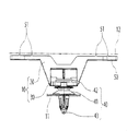
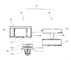
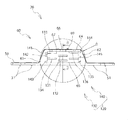
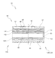
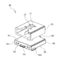
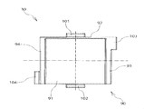
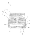
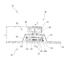
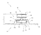
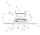
- FIG. 1 is an exploded perspective view of a bracket according to an embodiment of the present invention. It is a partial cross section figure which shows the attachment state of a bracket. It is a side view for demonstrating the attachment procedure of a bracket and a fastener. It is a perspective view of the base in one Embodiment by this invention. It is a front view of a base. It is a top view of a base. It is a side view of a base. It is an enlarged view of the A section of FIG. FIG. 6 is a cross-sectional view taken along line BB in FIG. 5. It is a perspective view of the attachment member in one Embodiment by this invention. It is a front view of an attachment member. It is a top view of an attachment member.
- FIG. 12 is a sectional view taken along the line CC of FIG. 11.
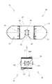
- FIG. 2 is an exploded plan view of a bracket when a mounting member is fitted in the direction A of FIG. 1. It is a front view of the bracket which shows the attachment state of FIG. It is sectional drawing which follows the DD line
- FIG. 2 is an exploded plan view of a bracket when a mounting member is fitted in a direction B of FIG. 1. It is a front view of the bracket which shows the attachment state of FIG.
- FIG. 20 is a cross-sectional view taken along the line EE of FIG.
- FIG. 2 is an exploded plan view of a bracket when a mounting member is fitted in a direction C of FIG. 1.
- FIG. 23 is a cross-sectional view taken along line FF in FIG. 22.
- FIG. 2 is an exploded plan view of a bracket when a mounting member is fitted in a direction D of FIG. 1. It is a front view of the bracket which shows the attachment state of FIG. FIG. 26 is a cross-sectional view taken along line GG in FIG. 25.
- Bracket 10 denotes a bracket according to an embodiment of the present invention.
- the bracket 10 is used to fix an automobile garnish 12 (decorative part) to an automobile panel 11.
- the bracket 10 is roughly composed of the following parts.
- the parts of the bracket 10 are not limited to the following (1) and (2).
- Pedestal 20 As shown in FIG. 2, the pedestal 20 is fixed to the automobile garnish 12 side.
- Mounting member 30 As shown in FIGS. 2 and 3, the attachment member 30 is fixed to the automobile panel 11 via a fastener 40.
- the pedestal 20 and the attachment member 30 are connected to each other by being fitted together, and the automobile garnish 12 is fixed to the automobile panel 11.
- the mounting member 30 is fixed to the automobile panel 11 via the fastener 40
- the present invention is not limited to this, and the mounting member 30 is directly fixed to the automobile panel 11 or parts other than the fastener 40 such as screws are attached. It may be used and fixed to the automobile panel 11.
- the pedestal 20 has a base portion 50 that is integrated with or fixed to the automobile garnish 12.
- the base portion 50 is formed separately from the automobile garnish 12 and is thermally welded to the automobile garnish 12.
- the base portion 50 is formed separately from the garnish 12 for an automobile, it may be formed integrally. Further, the pedestal 20 is heat-welded, but the present invention is not limited to this, and it may be bonded or screwed.
- the pedestal 20 has appropriate elasticity and rigidity, and is integrally formed of a thermoplastic synthetic resin such as PP (polypropylene).
- the pedestal 20 is roughly provided with the following parts.
- the following (1) and (2) will be described later.
- (1) Base part 50 (2) Base body 60
- Each part of the pedestal 20 is not limited to the above (1) and (2), and the pedestal main body 60 may be formed integrally with the garnish 12 for an automobile, for example.
- (Mounting member 30) As shown in FIGS. 1 and 15 to 26, the mounting member 30 can be fitted to the pedestal 20 from a plurality of directions, for example, from four directions A to D in FIG. 1, and the fitting direction is changed.
- the shaft portion 80 can be locked at a plurality of different height positions in the axial direction, for example, at four height positions.
- the mounting member 30 has appropriate elasticity and rigidity, and is integrally formed of, for example, a thermoplastic synthetic resin such as PP (polypropylene).
- the mounting member 30 is roughly divided into the following parts. The following (1) to (3) will be described later.
- Fixed part 70 (2) Shaft 80 (3) Locking part 90
- Each part of the attachment member 30 is not limited to the above (1) to (3).
- the fastener 40 As shown in FIGS. 2 and 3, the fastener 40 is located between the automobile panel 11 and a fixing portion 70 described later of the mounting member 30, and connects the two.
- the fastener 40 has moderate elasticity and rigidity, and is integrally formed of a thermoplastic synthetic resin. As shown in FIGS. 2 and 3, the fastener 40 is roughly divided into the following parts. Each part of the fastener 40 is not limited to the following (1) to (3).
- (1) Flange part 41 As shown in FIGS. 2 and 3, the flange portion 41 is located in the middle of the height of the fastener 40 and protrudes into a disk shape. The diameter of the flange portion 41 is set larger than the inner diameter of the through hole of the automobile panel 11.
- the boss portion 42 extends upward from the upper surface of the flange portion 41 and is fitted into a groove-like mounting portion 71 of a fixing portion 70 (to be described later) of the mounting member 30 to be attached. It is fixed to the member 30.
- the leg portion 43 is located on the opposite side of the boss portion 42 with the flange portion 41 interposed therebetween, and extends downward from the lower surface of the flange portion 41. Is fixed to the automobile panel 11.
- the leg portion 43 is formed in a shape in which the center of the height swells and the tip end portion becomes narrow, and the outer diameter of the swelled portion in the center is set slightly larger than the through hole of the automobile panel 11.
- the base portion 50 is formed in a plate shape as shown in FIGS. 4 to 6, and its bottom surface is thermally welded to the surface of the automobile garnish 12.
- the base portion 50 is formed separately from the garnish 12 for an automobile, it may be formed integrally.
- the base unit 50 includes the following units.
- each part of the base part 50 is not limited to following (1).
- Rib 51 As shown in FIGS. 4 and 5, a plurality of ribs 51 protrude from the bottom surface of the base portion 50.
- the rib 51 is welded to the automobile garnish 12 by heating.
- the pedestal main body 60 extends in a frame shape from the upper surface of the base portion 50, as shown in FIGS.
- the pedestal main body 60 includes the following parts. Each part of the pedestal main body 60 is not limited to the following (1) to (6).
- (1) Left side wall 61, right side wall 62 As shown in FIG. 4, the left side wall 61 and the right side wall 62 are located apart from each other in the left-right direction of the base portion 50 and extend upward from the upper surface of the base portion 50.
- the back wall 63 is positioned at one end in the width direction before and after the base portion 50, is adjacent to the left side wall 61 and the right side wall 62, and closes the rear surface of the hollow portion 65 described later.
- Lid wall 64 As shown in FIG. 4, the lid wall 64 is located away from the upper surface of the base portion 50, is adjacent to the left side wall 61, the right side wall 62, and the back wall 63, and closes the upper surface of the hollow portion 65 described later. It is.
- the hollow portion 65 is located on the inner side surrounded by the upper surface of the base portion 50, the left side wall 61, the right side wall 62, the back wall 63 and the lid wall 64, and the front surface is open.
- the hollow portion 65 is a portion into which a later-described locking portion 90 of the mounting member 30 is fitted, and the height of the hollow portion 65 is set higher than the height of the locking portion 90.
- the reason why the locking portion 90 is set higher in the hollow portion 65 is that the locking portion 90 can be moved up and down in the height direction of the hollow portion 65.
- Fitting groove 66, opening 67 As shown in FIG. 4, the fitting groove 66 penetrates the lid wall 64 in the vertical direction, has an opening 67 at one end, and is formed in a substantially U shape.
- the groove width of the fitting groove 66 is made to substantially coincide with the diameter of a shaft portion 80 described later of the mounting member 30.
- Overhang 68 As shown in FIGS. 4 and 6, the overhanging portion 68 is located between the fitting groove 66 and the opening 67, and the opening width of the opening 67 is smaller than the diameter of a shaft portion 80 described later of the mounting member 30. It is to narrow.
- Protrusion 69 A plurality of, for example, four protrusions 69 are formed around the fitting groove 66 and protrude from the upper surface of the lid wall 64 in a hemispherical shape.
- the protrusion 69 reduces the frictional resistance between the fixing portion 70 (described later) and the upper surface of the lid wall 64 when the shaft portion 80 (described later) of the mounting member 30 is fitted into the fitting groove 66. Is to do.
- the fixing portion 70 is fixed to the automobile panel 11 via the mounting portion 71 as shown in FIGS.
- the fixing portion 70 is formed in a hollow box shape with an open front surface.
- the fixing part 70 includes the following parts.
- fixed part 70 is not limited to following (1) and (2).
- (1) Mounting part 71 The mounting portion 71 is for mounting the fastener 40 as shown in FIG. As shown in FIGS. 10 to 12 and 14, the mounting portion 71 penetrates in the vertical direction, opens at one end, and is formed in a substantially U-shaped groove shape. The mounting portion 71 is fitted with the boss portion 42 of the fastener 40, and the fastener 40 is fixed to the fixing portion 70 via the boss portion 42.
- Protrusion 72 As shown in FIGS. 10 to 12 and FIG. 14, a plurality of, for example, four protrusions 72 are formed around the groove-shaped mounting portion 71 and protrude from the upper surface of the fixing portion 70 in a hemispherical shape. The protrusion 72 is in sliding contact with the boss portion 42 when the boss portion 42 of the fastener 40 is fitted into the groove-shaped mounting portion 71.
- shaft 80 As shown in FIGS. 2, 3, 11, and 14, the shaft portion 80 extends from the fixed portion 70 in the shape of a shaft and is fitted to the pedestal 20.
- the shaft portion 80 extends downward from the center of the lower surface of the fixing portion 70 in a columnar shape, and its lower end portion is connected to the center of the upper surface of the locking portion 90 described later. .
- the locking portion 90 is located on the opposite side of the fixing portion 70 with the shaft portion 80 interposed therebetween, and is pedestaled in a plurality of directions, for example, from four directions A to D in FIG. It can be fitted to 20, and can be locked at a plurality of height positions different in the axial direction of the shaft portion 80, for example, at four different height positions by changing the fitting direction.
- the locking portion 90 is formed in a hollow box shape with the lower and rear surfaces open.
- the locking portion 90 includes the following portions.
- locking part 90 is not limited to following (1)-(3).
- (1) Upper wall 91 The upper wall 91 is connected to the lower end portion of the shaft portion 80 as shown in FIGS.
- Front wall 92 The front wall 92 extends downward from the front edge of the upper wall 91 as shown in FIGS.
- Left side wall 93, right side wall 94 The left side wall 93 and the right side wall 94 extend downward from the left and right side edges of the upper wall 91 and are adjacent to the front wall 92, as shown in FIGS. (Height adjustment mechanism between pedestal body 60 and locking part 90) As shown in FIG. 1, a height adjustment mechanism for adjusting the axial height of the shaft portion 80 is provided between the pedestal main body 60 and the locking portion 90.
- the height adjusting mechanism is roughly divided into the following units. The following (1) and (2) will be described later.
- Convex part 100 (2) Recess 120
- the height adjusting mechanism is not limited to the structures (1) and (2) described above.
- Convex 100 As shown in FIG. 1, the convex portion 100 fits into a concave portion 120 described later, and is formed on one of the base body 60 and the locking portion 90, for example, the locking portion 90.
- the convex part 100 was formed in the latching
- the convex portion 100 is composed of a plurality of pieces, for example, a total of four pieces 101 to 104 described later, and the four pieces 101 to 104 protrude in a plurality of different directions.
- the axial heights of the shaft portions 80 are different from each other.
- the convex portion 100 is composed of four pieces 101 to 104, but may be composed of two, three, or five or more pieces.
- the convex portion 100 protrudes in a tongue shape and is formed in a plate shape that is long in the lateral direction.
- the convex portion 100 is composed of the following pieces 101 to 104 as shown in FIGS.
- the pieces 101 to 104 of the convex portion 100 are not limited to the following (1) to (4).
- (1) Front piece 101 The front piece 101 protrudes outward from the front wall 92 as shown in FIGS.
- the front piece 101 is located at the center of the left and right length directions of the front wall 92 and at the center of the height.
- Rear piece 102 The rear piece 102 protrudes outward from the rear edge of the upper wall 91 as shown in FIGS.
- the rear piece 102 is located at the center of the left and right length directions of the upper wall 91, and is located on the upper side, that is, the upper stage as compared with the front piece 101.
- (3) Left piece 103 The left piece 103 protrudes outward from the left side wall 93 as shown in FIGS.
- the left piece 103 is located on the rear side of the left side wall 93 and is located on the upper stage like the front piece 101.
- the right piece 104 protrudes outward from the right side wall 94 as shown in FIGS.
- the right piece 104 is located on the front side of the right side wall 94, and is located on the lower side, that is, the lower stage as compared with the front piece 101.
- the concave portion 120 fits into the convex portion 100, and is formed on the other of the pedestal main body 60 and the locking portion 90, for example, the pedestal main body 60.
- each part of the recessed part 120 is not limited to above-mentioned (1) and (2), You may comprise the recessed part 120 only from either one. (Hole part 130) As shown in FIGS. 8 and 9, the hole 130 is formed in the back wall 63 of the pedestal main body 60 so as to penetrate therethrough, and the pieces 101 to 104 of the locking portion 90 are fitted therein.
- the hole 130 is roughly composed of the following holes 131 to 136.
- the holes 131 to 136 of the hole 130 are not limited to the following (1) to (6), and the number is not limited to six.
- (1) Middle hole 131 As shown in FIGS. 8 and 9, the middle upper hole 131 is located at the center in the left and right length directions of the back wall 63 of the pedestal main body 60 and on the upper side in the height direction.
- Middle pilot hole 132 The middle lower hole 132 is located below the middle upper hole 131 as shown in FIGS. (3) Upper left hole 133 As shown in FIG. 8, the upper left hole 133 is located on the left side of the middle upper hole 131 and is located above the middle upper hole 131.
- the lower left hole 134 is located below the upper left hole 133 and is located between the middle upper hole 131 and the middle lower hole 132.
- Upper right hole 135 As shown in FIG. 8, the upper right hole 135 is located on the right side of the middle upper hole 131 and is located at the same height as the upper left hole 133.
- the lower right hole 136 is located below the upper right hole 135 and is located at the same height as the lower left hole 134.
- the groove portions 140 are respectively formed on the inner surfaces of the left side wall 93 and the right side wall 94 facing each other, and are formed long in the front-rear direction of the left side wall 93 and the right side wall 94.
- the groove 140 is roughly composed of the following grooves 141 to 146.
- the grooves 141 to 146 of the hole 130 are not limited to the following (1) to (6), and the number is not limited to six.
- (1) Upper left groove 141 The upper left groove 141 is positioned above the left side wall 93 as shown in FIGS.
- Left middle groove 142 The left middle groove 142 is located on the lower side of the upper left groove 141 as shown in FIGS. (3) Left lower groove 143 The lower left groove 143 is located below the left middle groove 142 as shown in FIGS. (4) Upper right groove 144 As shown in FIG. 8, the upper right groove 144 is located above the right side wall 94 and is located at the same height as the upper left groove 141.
- Right middle groove 145 As shown in FIG. 8, the right middle groove 145 is located below the upper right groove 144 and is located between the left middle groove 142 and the lower left groove 143.
- Lower right groove 146 As shown in FIG. 8, the lower right groove 146 is located below the right middle groove 145 and is located slightly higher than the lower left groove 143. (Mounting method of bracket 10) A method for attaching the bracket 10 having the above-described configuration will be described.
- the pedestal 20 is heat-welded at the bottom surface of the base portion 50 to the surface of the automobile garnish 12.
- the fastener 40 is fitted into the mounting portion 71 of the fixing portion 70 of the mounting member 30 to fix the fastener 40 to the mounting member 30.
- the shaft portion 80 of the mounting member 30 is fitted in the opening 67 of the base 20 and positioned in the fitting groove 66 as shown in FIGS.
- the locking portion 90 of the mounting member 30 is fitted inside from the open surface of the hollow portion 65 of the base 20.
- the fastener 40 is fixed to the automobile garnish 12 via the bracket 10.
- the leg portion 43 of the fastener 40 is inserted into the through-hole of the automobile panel 11 as shown in FIG. Accordingly, the automobile garnish 12 is fixed to the automobile panel 11 via the fastener 40 bracket 10.
- the attachment member 30 was fitted into the pedestal 20, and finally the fastener 40 was fixed to the automobile panel 11.
- the attachment procedure is not limited, and the fastener 40 is attached. Without attaching the mounting member 30 to the pedestal 20 and then attaching the fastener 40, or after fixing the fastener 40 to the automobile panel 11, it is attached to the mounting member 30, and the mounting member 30 is finally attached to the pedestal 20.
- the fastener 40 may be finally attached to the attachment member 30 after the attachment member 30 is attached to the base 20.
- the right piece 104 of the locking portion 90 fits into the lower left groove 143 of the left side wall 61 of the base 20, as shown in FIG.
- the left piece 103 of the locking portion 90 fits into the right middle groove 145 of the right side wall 62 of the base 20.
- the front piece 101 of the locking portion 90 fits into the middle and lower hole 132 of the base 20.
- the left piece 103 of the locking portion 90 fits into the left middle groove 142 of the left side wall 61 of the base 20, as shown in FIG.
- the right piece 104 of the locking portion 90 fits into the lower right groove 146 of the right side wall 62 of the base 20.
- the rear piece 102 of the locking portion 90 fits into the middle upper hole 131 of the base 20.
- the rear piece 102 of the locking portion 90 fits into the upper left groove 141 of the left side wall 61 of the base 20, as shown in FIG.
- the front piece 101 of the locking portion 90 fits into the right middle groove 145 of the right side wall 62 of the base 20.
- the right piece 104 of the locking portion 90 fits into the lower right hole 136 of the base 20.
- the front piece 101 of the locking portion 90 fits into the left middle groove 142 of the left side wall 61 of the base 20, as shown in FIG.
- the rear piece 102 of the locking portion 90 fits into the upper right groove 144 of the right side wall 62 of the base 20.
- the left piece 103 of the locking portion 90 fits into the upper right hole 135 of the base 20.
Landscapes
- Engineering & Computer Science (AREA)
- General Engineering & Computer Science (AREA)
- Mechanical Engineering (AREA)
- Connection Of Plates (AREA)
- Vehicle Interior And Exterior Ornaments, Soundproofing, And Insulation (AREA)
- Insertion Pins And Rivets (AREA)
Abstract
ブラケットは、台座と、取付部材とを備える。台座は、自動車用ガーニッシュと一体若しくは固着されるベース部を有するものである。取付部材は、ファスナーを介して自動車パネルに固定される固定部、固定部から軸状に延び、台座に嵌合する軸部、軸部をはさんで固定部と反対側に位置し、複数の方向から台座に対し嵌合可能であり、当該嵌合する方向を変更することにより、軸部の軸方向の異なる複数位置に係止可能な係止部を有するものである。
Description
この発明は、自動車パネルに自動車用ガーニッシュ(装飾部品)を固定するためのブラケットに関し、台座に対し、取付部材の組み付け方向を変えることにより、取付部材の高さを所望の複数の高さ位置に、容易に取り付けることができるようにしたものである。
従来、内筒であるベース部材と、当該ベース部材に外嵌する外筒であるファスナー部材の内外周面に、互いにはまり合う鋸歯状の凹部と凸部とを複数段設け、ベース部材に対するファスナー部材の高さを段階的に調節することができるようにしたファスナーブラケットが知られている(特許文献1の段落番号「0016」及び「0017」、図2及び図6参照)。
また、従来、ガーニッシュに座部を一体に成形し、クリップに組付部を一体に成形し、座部に複数段の凹部を設け、組付部に前記凹部に嵌合する複数段の凸部を設けたクリップが知られている(特許文献1の段落番号「0009」、「0014」、「00015」、図1及び図4~図6参照)。
しかし、上記した従来の前者のファスナーブラケット(実開平6-59612号公報)では、ベース部材に対するファスナー部材の高さを段階的に調節するようにしていたので、ファスナー部材を所望の高さ位置に停止させるのが困難であるという第1の問題点があった。
また、上記した従来の後者のクリップでは、組付部がクリップに一体に成形されていたので、既存のクリップが使用できず、汎用性に乏しいという第2の問題点があった。
また、上記した従来の後者のクリップでは、組付部がクリップに一体に成形されていたので、既存のクリップが使用できず、汎用性に乏しいという第2の問題点があった。
そこで、本発明は、上記した従来の技術の有する第1及び第2問題点に鑑みてなされたものであり、その目的とするところは、台座に対し、取付部材の組み付け方向を変えることにより、取付部材の高さを所望の複数の高さ位置に、容易に取り付けることができるようにしたものである。これに加え、本発明は、ファスナーを介して自動車パネルに取付部材を固定することができるようにしたものである。
本発明は、上記した目的を達成するためになされたものであり、本発明は、次の点を特徴とする。
第1に、ブラケットは、次の構成を備える。
(1)台座
(2)取付部材
第2に、台座は、自動車用ガーニッシュと一体若しくは固着されるベース部を有するものである。
(1)台座
(2)取付部材
第2に、台座は、自動車用ガーニッシュと一体若しくは固着されるベース部を有するものである。
第3に、取付部材は、ファスナーを介して自動車パネルに固定される固定部、固定部から軸状に延び、台座に嵌合する軸部、軸部をはさんで固定部と反対側に位置し、複数の方向から台座に対し嵌合可能であり、当該嵌合する方向を変更することにより、軸部の軸方向の異なる複数の高さ位置に係止可能な係止部を有するものである。
本発明は、次の点を特徴としてもよい。
本発明は、次の点を特徴としてもよい。
第1に、係止部と台座との両対向面のどちらか一方(例えば係止部)には、他方(台座)に向かって突出した凸部を形成する。
第2に、他方(台座)には、凸部にはまり合う凹部を形成する。
第3に、凸部と凹部とは、軸部の軸方向の高さを略一致させている。
この態様では、凹凸形状により、取付部材の高さを調節することができる。
本発明は、次の点を特徴としてもよい。
第2に、他方(台座)には、凸部にはまり合う凹部を形成する。
第3に、凸部と凹部とは、軸部の軸方向の高さを略一致させている。
この態様では、凹凸形状により、取付部材の高さを調節することができる。
本発明は、次の点を特徴としてもよい。
第1に、凸部は、係止部と台座との両対向面のどちらか一方に複数個形成される。
第2に、複数個の凸部は、異なる複数の方向に向かって突出するとともに、軸部の軸方向の高さを互いに異ならせている。
この態様では、凸部を複数個形成し、軸部の軸方向の高さを互いに異ならせることで、凸部を利用して、取付部材の高さを調節することができる。これに加え、異なる高さの凸部を、複数の方向から突出させることで、複数の方向から取付部材を組み付けることができる。
本発明は、次の点を特徴としてもよい。
第2に、複数個の凸部は、異なる複数の方向に向かって突出するとともに、軸部の軸方向の高さを互いに異ならせている。
この態様では、凸部を複数個形成し、軸部の軸方向の高さを互いに異ならせることで、凸部を利用して、取付部材の高さを調節することができる。これに加え、異なる高さの凸部を、複数の方向から突出させることで、複数の方向から取付部材を組み付けることができる。
本発明は、次の点を特徴としてもよい。
第1に、凹部は、係止部と台座との両対向面のどちらか他方に複数個形成される。
第2に、複数個の凹部は、軸部の軸方向の高さを互いに異ならせている。
この態様では、凹部を複数個形成し、軸部の軸方向の高さを互いに異ならせることで、凹部を利用して、取付部材の高さを調節することができる。
本発明は、次の点を特徴としてもよい。
第2に、複数個の凹部は、軸部の軸方向の高さを互いに異ならせている。
この態様では、凹部を複数個形成し、軸部の軸方向の高さを互いに異ならせることで、凹部を利用して、取付部材の高さを調節することができる。
本発明は、次の点を特徴としてもよい。
すなわち、固定部は、自動車パネルにファスナーを介して固定されるとともに、ファスナーを装着する装着部が設けられている。
この態様では、既存のファスナーを、固定部の装着部の装着することができる。
本発明は、次の点を特徴としてもよい。
この態様では、既存のファスナーを、固定部の装着部の装着することができる。
本発明は、次の点を特徴としてもよい。
第1に、台座には、軸部を受け入れ可能な開口を有する嵌合溝を形成する。
第2に、開口の幅を、軸部の直径より小さく設定し、台座の弾性を利用して軸部を嵌合溝にはめ込むようにしている。
この態様では、台座の弾性を利用して、軸部を台座の嵌合溝にはめ込むことができ、又、はめ込んだ後は、開口の幅が軸部の直径より小さくなることで、嵌合溝から軸部の抜けを防止することができる。
第2に、開口の幅を、軸部の直径より小さく設定し、台座の弾性を利用して軸部を嵌合溝にはめ込むようにしている。
この態様では、台座の弾性を利用して、軸部を台座の嵌合溝にはめ込むことができ、又、はめ込んだ後は、開口の幅が軸部の直径より小さくなることで、嵌合溝から軸部の抜けを防止することができる。
本発明は、以上のように構成されているので、台座に対し、取付部材の組み付け方向を変えることにより、取付部材の高さを所望の複数の高さ位置に、容易に取り付けることができる。これに加え、ファスナーを介して自動車パネルに取付部材を固定することができる。このため、既存のファスナーを使用できるので、ブラケットの汎用を向上することができる。
(ブラケット10)
図1~3中、10は、本発明による1実施形態によるブラケットを示し、このブラケット10は、自動車パネル11に自動車用ガーニッシュ12(装飾部品)を固定するのに使用される。
ブラケット10は、図1に示すように、大別すると、次のパーツから構成されている。
なお、ブラケット10のパーツは、次の(1)及び(2)に限定されない。
図1~3中、10は、本発明による1実施形態によるブラケットを示し、このブラケット10は、自動車パネル11に自動車用ガーニッシュ12(装飾部品)を固定するのに使用される。
ブラケット10は、図1に示すように、大別すると、次のパーツから構成されている。
なお、ブラケット10のパーツは、次の(1)及び(2)に限定されない。
(1)台座20
台座20は、図2に示すように、自動車用ガーニッシュ12側に固定される。
(2)取付部材30
取付部材30は、図2及び図3に示すように、ファスナー40を介して自動車パネル11に固定される。台座20と取付部材30とは、互いにはまり合うことで連結され、自動車パネル11に対し、自動車用ガーニッシュ12が固定される。
台座20は、図2に示すように、自動車用ガーニッシュ12側に固定される。
(2)取付部材30
取付部材30は、図2及び図3に示すように、ファスナー40を介して自動車パネル11に固定される。台座20と取付部材30とは、互いにはまり合うことで連結され、自動車パネル11に対し、自動車用ガーニッシュ12が固定される。
なお、取付部材30を、ファスナー40を介して自動車パネル11に固定したが、これに限定されず、取付部材30を自動車パネル11に直接固定したり、或いはファスナー40以外のパーツ、例えばネジ等を使用して自動車パネル11に固定しても良い。
(台座20)
台座20は、図1及び図2に示すように、自動車用ガーニッシュ12と一体若しくは固着されるベース部50を有するものである。本実施の形態では、ベース部50を自動車用ガーニッシュ12と別体に形成し、自動車用ガーニッシュ12に熱溶着している。
(台座20)
台座20は、図1及び図2に示すように、自動車用ガーニッシュ12と一体若しくは固着されるベース部50を有するものである。本実施の形態では、ベース部50を自動車用ガーニッシュ12と別体に形成し、自動車用ガーニッシュ12に熱溶着している。
なお、ベース部50を、自動車用ガーニッシュ12と別体に形成したが、一体的に形成するようにしても良い。また、台座20を熱溶着したが、これに限定されず、接着したり、或いはネジ止めしても良い。
台座20は、適度な弾性と剛性とを有し、例えばPP(ポリプロピレン)等の熱可塑性合成樹脂により一体的に成形される。
台座20は、適度な弾性と剛性とを有し、例えばPP(ポリプロピレン)等の熱可塑性合成樹脂により一体的に成形される。
台座20は、図4~9に示すように、大別すると、次の各部を備える。
なお、次の(1)及び(2)については、後述する。
(1)ベース部50
(2)台座本体60
なお、台座20の各部は、上記した(1)及び(2)に限定されず、例えば台座本体60を自動車用ガーニッシュ12に一体的に形成しても良い。
(取付部材30)
取付部材30は、図1及び図15~26に示すように、複数の方向、例えば図1のA~Dの四方から台座20に対し嵌合可能であり、当該嵌合する方向を変更することにより、軸部80の軸方向の異なる複数の高さ位置、例えば4段階の高さ位置に係止可能なものである。
なお、次の(1)及び(2)については、後述する。
(1)ベース部50
(2)台座本体60
なお、台座20の各部は、上記した(1)及び(2)に限定されず、例えば台座本体60を自動車用ガーニッシュ12に一体的に形成しても良い。
(取付部材30)
取付部材30は、図1及び図15~26に示すように、複数の方向、例えば図1のA~Dの四方から台座20に対し嵌合可能であり、当該嵌合する方向を変更することにより、軸部80の軸方向の異なる複数の高さ位置、例えば4段階の高さ位置に係止可能なものである。
なお、取付部材30を嵌合する方向として、四方を例示したが、これに限定されず、四方のうち、2方向や3方向、或いは5方向以上としても良い。また、取付部材30の高さの調節位置として、4段階を例示したが、これに限定されず、2段階、3段階、或いは5段階以上としても良い。
取付部材30は、台座20と同様に、適度な弾性と剛性とを有し、例えばPP(ポリプロピレン)等の熱可塑性合成樹脂により一体的に成形される。
取付部材30は、台座20と同様に、適度な弾性と剛性とを有し、例えばPP(ポリプロピレン)等の熱可塑性合成樹脂により一体的に成形される。
取付部材30は、図10~14に示すように、大別すると、次の各部を備える。
なお、次の(1)~(3)については、後述する。
(1)固定部70
(2)軸部80
(3)係止部90
なお、取付部材30のの各部は、上記した(1)~(3)に限定されない。
(ファスナー40)
ファスナー40は、図2及び図3に示すように、自動車パネル11と取付部材30の後述する固定部70との間に位置し、両者を連結するものである。
なお、次の(1)~(3)については、後述する。
(1)固定部70
(2)軸部80
(3)係止部90
なお、取付部材30のの各部は、上記した(1)~(3)に限定されない。
(ファスナー40)
ファスナー40は、図2及び図3に示すように、自動車パネル11と取付部材30の後述する固定部70との間に位置し、両者を連結するものである。
ファスナー40は、適度な弾性と剛性とを有し、熱可塑性合成樹脂により一体的に成形される。
ファスナー40は、図2及び図3に示すように、大別すると、次の各部を備える。
なお、ファスナー40の各部は、次の(1)~(3)に限定されない。
(1)フランジ部41
フランジ部41は、図2及び図3に示すように、ファスナー40の高さの途中に位置し、円盤形に張り出している。フランジ部41の直径は、自動車パネル11の貫通孔の内径より大きく設定されている。
ファスナー40は、図2及び図3に示すように、大別すると、次の各部を備える。
なお、ファスナー40の各部は、次の(1)~(3)に限定されない。
(1)フランジ部41
フランジ部41は、図2及び図3に示すように、ファスナー40の高さの途中に位置し、円盤形に張り出している。フランジ部41の直径は、自動車パネル11の貫通孔の内径より大きく設定されている。
(2)ボス部42
ボス部42は、図2及び図3に示すように、フランジ部41の上面から上方に向かって延び、取付部材30の後述する固定部70の溝状の装着部71にはまり込むことで、取付部材30に対して固定されている。
(3)脚部43
脚部43は、図2及び図3に示すように、フランジ部41をはさんでボス部42と反対側に位置し、フランジ部41の下面から下方に向かって延び、自動車パネル11の貫通孔に挿入されることで、自動車パネル11に対して固定される。脚部43は、高さの中央が膨らみ、先端部が細くなった形状に形成され、中央の膨らんだ部分の外径を、自動車パネル11の貫通孔より少し大きく設定している。
ボス部42は、図2及び図3に示すように、フランジ部41の上面から上方に向かって延び、取付部材30の後述する固定部70の溝状の装着部71にはまり込むことで、取付部材30に対して固定されている。
(3)脚部43
脚部43は、図2及び図3に示すように、フランジ部41をはさんでボス部42と反対側に位置し、フランジ部41の下面から下方に向かって延び、自動車パネル11の貫通孔に挿入されることで、自動車パネル11に対して固定される。脚部43は、高さの中央が膨らみ、先端部が細くなった形状に形成され、中央の膨らんだ部分の外径を、自動車パネル11の貫通孔より少し大きく設定している。
このため、脚部43を自動車パネル11の貫通孔に合わせて挿入すると、貫通孔の内縁部に押され、中央の膨らんだ部分の外径が弾性的に縮径し、貫通孔を通過後、自動車パネル11の下側で、樹脂の弾性力により復元する。このため、中央の膨らんだ部分と、フランジ部41との間で、自動車パネル11をその厚み方向にはさみ持つことで、貫通孔に対してファスナー40が固定される。
(ベース部50)
ベース部50は、図1及び図2に示すように、自動車用ガーニッシュ12と一体若しくは固着されるものである。
(ベース部50)
ベース部50は、図1及び図2に示すように、自動車用ガーニッシュ12と一体若しくは固着されるものである。
本実施の形態においては、ベース部50は、図4~6に示すように、板状に形成され、その底面を自動車用ガーニッシュ12の表面に熱溶着している。
なお、ベース部50を、自動車用ガーニッシュ12と別体に形成したが、一体的に形成するようにしても良い。
ベース部50は、図4及び図5に示すように、次の各部を備える。
なお、ベース部50を、自動車用ガーニッシュ12と別体に形成したが、一体的に形成するようにしても良い。
ベース部50は、図4及び図5に示すように、次の各部を備える。
なお、ベース部50の各部は、次の(1)に限定されない。
(1)リブ51
リブ51は、図4及び図5に示すように、ベース部50の底面から複数個、突出する。リブ51は、加熱することで、自動車用ガーニッシュ12に溶着する。
(台座本体60)
台座本体60は、図4~9に示すように、ベース部50の上面から枠状に延びる。
(1)リブ51
リブ51は、図4及び図5に示すように、ベース部50の底面から複数個、突出する。リブ51は、加熱することで、自動車用ガーニッシュ12に溶着する。
(台座本体60)
台座本体60は、図4~9に示すように、ベース部50の上面から枠状に延びる。
台座本体60は、図4~9に示すように、次の各部を備える。
なお、台座本体60の各部は、次の(1)~(6)に限定されない。
(1)左側壁61、右側壁62
左側壁61、右側壁62は、図4に示すように、ベース部50の左右方向に離れて位置し、ベース部50の上面から上方に向かって延びる。
なお、台座本体60の各部は、次の(1)~(6)に限定されない。
(1)左側壁61、右側壁62
左側壁61、右側壁62は、図4に示すように、ベース部50の左右方向に離れて位置し、ベース部50の上面から上方に向かって延びる。
(2)奥壁63
奥壁63は、図9に示すように、ベース部50の前後の幅方向の一端部に位置し、左側壁61及び右側壁62に隣接し、後述する中空部65の後面を塞ぐものである。
(3)蓋壁64
蓋壁64は、図4に示すように、ベース部50の上面から上方に離れて位置し、左側壁61、右側壁62及び奥壁63に隣接し、後述する中空部65の上面を塞ぐものである。
奥壁63は、図9に示すように、ベース部50の前後の幅方向の一端部に位置し、左側壁61及び右側壁62に隣接し、後述する中空部65の後面を塞ぐものである。
(3)蓋壁64
蓋壁64は、図4に示すように、ベース部50の上面から上方に離れて位置し、左側壁61、右側壁62及び奥壁63に隣接し、後述する中空部65の上面を塞ぐものである。
(4)中空部65
中空部65は、図4に示すように、ベース部50の上面、左側壁61、右側壁62、奥壁63及び蓋壁64で囲まれた内側に位置し、前面が開放する。
中空部65は、取付部材30の後述する係止部90がはまり込むものであり、中空部65の高さを係止部90の高さより高く設定している。中空部65を係止部90を高く設定しているのは、中空部65の高さ方向において、係止部90を上下動できるようにするためである。
中空部65は、図4に示すように、ベース部50の上面、左側壁61、右側壁62、奥壁63及び蓋壁64で囲まれた内側に位置し、前面が開放する。
中空部65は、取付部材30の後述する係止部90がはまり込むものであり、中空部65の高さを係止部90の高さより高く設定している。中空部65を係止部90を高く設定しているのは、中空部65の高さ方向において、係止部90を上下動できるようにするためである。
(4)嵌合溝66、開口67
嵌合溝66は、図4に示すように、蓋壁64を上下方向に貫通し、一端に開口67を有し、略U字形に形成されている。嵌合溝66の溝幅は、取付部材30の後述する軸部80の直径に略一致させている。
(5)張出部68
張出部68は、図4及び図6に示すように、嵌合溝66と開口67との間に位置し、開口67の開口幅を、取付部材30の後述する軸部80の直径より小さく狭めるものである。
嵌合溝66は、図4に示すように、蓋壁64を上下方向に貫通し、一端に開口67を有し、略U字形に形成されている。嵌合溝66の溝幅は、取付部材30の後述する軸部80の直径に略一致させている。
(5)張出部68
張出部68は、図4及び図6に示すように、嵌合溝66と開口67との間に位置し、開口67の開口幅を、取付部材30の後述する軸部80の直径より小さく狭めるものである。
(6)突起69
突起69は、嵌合溝66の周囲に複数個、例えば4個形成され、蓋壁64の上面から半球形に突出する。突起69は、取付部材30の後述する軸部80を嵌合溝66にはめ込む際に、同じく後述する固定部70と蓋壁64の上面とが接した際に、両者の間の摩擦抵抗を低減するためのものである。
(固定部70)
固定部70は、図1~3に示すように、装着部71を介して自動車パネル11に固定されるものである。
突起69は、嵌合溝66の周囲に複数個、例えば4個形成され、蓋壁64の上面から半球形に突出する。突起69は、取付部材30の後述する軸部80を嵌合溝66にはめ込む際に、同じく後述する固定部70と蓋壁64の上面とが接した際に、両者の間の摩擦抵抗を低減するためのものである。
(固定部70)
固定部70は、図1~3に示すように、装着部71を介して自動車パネル11に固定されるものである。
固定部70は、図10~12及び図14に示すように、前面が開放した中空の箱形に形成されている。
固定部70は、図10~12及び図14に示すように、次の各部を備える。
なお、固定部70の各部は、次の(1)及び(2)に限定されない。
(1)装着部71
装着部71は、図2に示すように、ファスナー40を装着するものである。装着部71は、図10~12及び図14に示すように、上下方向に貫通し、一端に開口し、略U字形の溝状に形成されている。装着部71には、ファスナー40のボス部42がはめ込まれ、ボス部42を介してファスナー40が固定部70に固定される。
固定部70は、図10~12及び図14に示すように、次の各部を備える。
なお、固定部70の各部は、次の(1)及び(2)に限定されない。
(1)装着部71
装着部71は、図2に示すように、ファスナー40を装着するものである。装着部71は、図10~12及び図14に示すように、上下方向に貫通し、一端に開口し、略U字形の溝状に形成されている。装着部71には、ファスナー40のボス部42がはめ込まれ、ボス部42を介してファスナー40が固定部70に固定される。
(2)突起72
突起72は、図10~12及び図14に示すように、溝状の装着部71の周囲に複数個、例えば4個形成され、固定部70の上面から半球形に突出する。突起72は、ファスナー40のボス部42を溝状の装着部71にはめ込んだ際に、ボス部42と摺接する。
(軸部80)
軸部80は、図2、図3、図11及び図14に示すように、固定部70から軸状に延び、台座20に嵌合するものである。
突起72は、図10~12及び図14に示すように、溝状の装着部71の周囲に複数個、例えば4個形成され、固定部70の上面から半球形に突出する。突起72は、ファスナー40のボス部42を溝状の装着部71にはめ込んだ際に、ボス部42と摺接する。
(軸部80)
軸部80は、図2、図3、図11及び図14に示すように、固定部70から軸状に延び、台座20に嵌合するものである。
軸部80は、図11及び図14に示すように、固定部70の下面の中央から下方に向かって円柱状に延び、その下端部が後述する係止部90の上面の中央に連設する。
(係止部90)
係止部90は、図1及び図10~14に示すように、軸部80をはさんで固定部70と反対側に位置し、複数の方向、例えば図1のA~Dの四方から台座20に対し嵌合可能であり、当該嵌合する方向を変更することにより、軸部80の軸方向の異なる複数の高さ位置、例えば4段階の高さ位置に係止可能なものである。
(係止部90)
係止部90は、図1及び図10~14に示すように、軸部80をはさんで固定部70と反対側に位置し、複数の方向、例えば図1のA~Dの四方から台座20に対し嵌合可能であり、当該嵌合する方向を変更することにより、軸部80の軸方向の異なる複数の高さ位置、例えば4段階の高さ位置に係止可能なものである。
なお、係止部90を嵌合する方向として、四方を例示したが、これに限定されず、四方のうち、2方向や3方向、或いは5方向以上としても良い。また、係止部90の高さの調節位置として、4段階を例示したが、これに限定されず、2段階、3段階、或いは5段階以上としても良い。
係止部90は、図10~14に示すように、下面及び後面が開放した中空の箱形に形成されている。
係止部90は、図10~14に示すように、下面及び後面が開放した中空の箱形に形成されている。
係止部90は、図10~14に示すように、次の各部を備える。
なお、係止部90の各部は、次の(1)~(3)に限定されない。
(1)上壁91
上壁91は、図11及び図14に示すように、軸部80の下端部に連設する。
(2)前壁92
前壁92は、図10~14に示すように、上壁91の前縁部から下方に向かって延びる。
なお、係止部90の各部は、次の(1)~(3)に限定されない。
(1)上壁91
上壁91は、図11及び図14に示すように、軸部80の下端部に連設する。
(2)前壁92
前壁92は、図10~14に示すように、上壁91の前縁部から下方に向かって延びる。
(3)左側壁93、右側壁94
左側壁93、右側壁94は、図10~14に示すように、上壁91の左右の両側縁部から下方に向かって延び、前壁92に隣接している。
(台座本体60と係止部90との間の高さ調節機構)
台座本体60と係止部90との間には、図1に示すように、軸部80の軸方向の高さを調節するための高さ調節機構を設けている。
左側壁93、右側壁94は、図10~14に示すように、上壁91の左右の両側縁部から下方に向かって延び、前壁92に隣接している。
(台座本体60と係止部90との間の高さ調節機構)
台座本体60と係止部90との間には、図1に示すように、軸部80の軸方向の高さを調節するための高さ調節機構を設けている。
高さ調節機構は、図1に示すように、大別すると、次の各部を備える。
なお、次の(1)及び(2)については、後述する。
(1)凸部100
(2)凹部120
なお、高さ調節機構は、上記した(1)及び(2)の構造に限定されない。
(凸部100)
凸部100は、図1に示すように、後述する凹部120にはまり込むのであり、台座本体60と係止部90とのどちらか一方、例えば係止部90に形成されている。
なお、次の(1)及び(2)については、後述する。
(1)凸部100
(2)凹部120
なお、高さ調節機構は、上記した(1)及び(2)の構造に限定されない。
(凸部100)
凸部100は、図1に示すように、後述する凹部120にはまり込むのであり、台座本体60と係止部90とのどちらか一方、例えば係止部90に形成されている。
なお、凸部100を係止部90に形成したが、逆に台座本体60側に形成しても良い。
凸部100は、図10~14に示すように、複数個、例えば計4個の、後述する片101~104から構成され、4個の片101~104は、異なる複数の方向に向かって突出するとともに、軸部80の軸方向の高さを互いに異ならせている。
なお、凸部100を、4個の片101~104から構成したが、2個、3個或いは5個以上の片から構成しても良い。
凸部100は、図10~14に示すように、複数個、例えば計4個の、後述する片101~104から構成され、4個の片101~104は、異なる複数の方向に向かって突出するとともに、軸部80の軸方向の高さを互いに異ならせている。
なお、凸部100を、4個の片101~104から構成したが、2個、3個或いは5個以上の片から構成しても良い。
凸部100は、図10~14に示すように、舌片状に突出し、横方向に長い板状に形成されている。
凸部100は、図10~14に示すように、次の各片101~104から構成されている。
なお、凸部100の各片101~104は、次の(1)~(4)に限定されない。
(1)前片101
前片101は、図10~14に示すように、前壁92から外向きに突出する。前片101は、前壁92の左右の長さ方向の中央で、且つ高さの中央に位置する。
凸部100は、図10~14に示すように、次の各片101~104から構成されている。
なお、凸部100の各片101~104は、次の(1)~(4)に限定されない。
(1)前片101
前片101は、図10~14に示すように、前壁92から外向きに突出する。前片101は、前壁92の左右の長さ方向の中央で、且つ高さの中央に位置する。
(2)後片102
後片102は、図12~14に示すように、上壁91の後縁部から外向きに突出する。後片102は、上壁91の左右の長さ方向の中央に位置し、前片101と比較して上側、すなわち上段に位置する。
(3)左片103
左片103は、図10~13に示すように、左側壁93から外向きに突出する。左片103は、左側壁93の後側に位置し、前片101と同様に上段に位置する。
後片102は、図12~14に示すように、上壁91の後縁部から外向きに突出する。後片102は、上壁91の左右の長さ方向の中央に位置し、前片101と比較して上側、すなわち上段に位置する。
(3)左片103
左片103は、図10~13に示すように、左側壁93から外向きに突出する。左片103は、左側壁93の後側に位置し、前片101と同様に上段に位置する。
(4)右片104
右片104は、図10~13に示すように、右側壁94から外向きに突出する。右片104は、右側壁94の前側に位置し、前片101と比較して下側、すなわち下段に位置する。
(凹部120)
凹部120は、図1に示すように、凸部100にはまり合うものであり、台座本体60と係止部90とのどちらか他方、例えば台座本体60に形成されている。
右片104は、図10~13に示すように、右側壁94から外向きに突出する。右片104は、右側壁94の前側に位置し、前片101と比較して下側、すなわち下段に位置する。
(凹部120)
凹部120は、図1に示すように、凸部100にはまり合うものであり、台座本体60と係止部90とのどちらか他方、例えば台座本体60に形成されている。
なお、凹部120を台座本体60に形成したが、逆に係止部90側に形成しても良い。
凹部120は、図8及び図9に示すように、大別すると、次の各部から構成されている。
なお、次の(1)及び(2)については、後述する。
(1)穴部130
(2)溝部140
なお、凹部120の各部は、上記した(1)及び(2)に限定されず、いずれか一方のみから凹部120を構成しても良い。
(穴部130)
穴部130は、図8及び図9に示すように、台座本体60の奥壁63に貫通状に形成され、係止部90の各片101~104がはまり込むものである。
凹部120は、図8及び図9に示すように、大別すると、次の各部から構成されている。
なお、次の(1)及び(2)については、後述する。
(1)穴部130
(2)溝部140
なお、凹部120の各部は、上記した(1)及び(2)に限定されず、いずれか一方のみから凹部120を構成しても良い。
(穴部130)
穴部130は、図8及び図9に示すように、台座本体60の奥壁63に貫通状に形成され、係止部90の各片101~104がはまり込むものである。
穴部130は、図8及び図9に示すように、大別すると、次の各穴131~136から構成されている。
なお、穴部130の穴131~136は、次の(1)~(6)に限定されず、又、個数も6個に限定されない。
(1)中上穴131
中上穴131は、図8及び図9に示すように、台座本体60の奥壁63の左右の長さ方向の中央で、且つ高さの方向の上側に位置する。
なお、穴部130の穴131~136は、次の(1)~(6)に限定されず、又、個数も6個に限定されない。
(1)中上穴131
中上穴131は、図8及び図9に示すように、台座本体60の奥壁63の左右の長さ方向の中央で、且つ高さの方向の上側に位置する。
(2)中下穴132
中下穴132は、図8及び図9に示すように、中上穴131の下側に位置する。
(3)左上穴133
左上穴133は、図8に示すように、中上穴131の左側に位置し、当該中上穴131より上方に位置する。
中下穴132は、図8及び図9に示すように、中上穴131の下側に位置する。
(3)左上穴133
左上穴133は、図8に示すように、中上穴131の左側に位置し、当該中上穴131より上方に位置する。
(4)左下穴134
左下穴134は、図8に示すように、左上穴133の下側に位置し、中上穴131と中下穴132との中間に位置する。
(5)右上穴135
右上穴135は、図8に示すように、中上穴131の右側に位置し、左上穴133と同じ高さに位置する。
左下穴134は、図8に示すように、左上穴133の下側に位置し、中上穴131と中下穴132との中間に位置する。
(5)右上穴135
右上穴135は、図8に示すように、中上穴131の右側に位置し、左上穴133と同じ高さに位置する。
(6)右下穴136
右下穴136は、図8に示すように、右上穴135の下側に位置し、左下穴134と同じ高さに位置する。
(溝部140)
溝部140は、図8及び図9に示すように、左側壁93と右側壁94の相対向する内側面にそれぞれ形成され、左側壁93及び右側壁94の前後方向に長く形成されている。
右下穴136は、図8に示すように、右上穴135の下側に位置し、左下穴134と同じ高さに位置する。
(溝部140)
溝部140は、図8及び図9に示すように、左側壁93と右側壁94の相対向する内側面にそれぞれ形成され、左側壁93及び右側壁94の前後方向に長く形成されている。
溝部140は、図8及び図9に示すように、大別すると、次の各溝141~146から構成されている。
なお、穴部130の溝141~146は、次の(1)~(6)に限定されず、又、個数も6個に限定されない。
(1)左上溝141
左上溝141は、図8及び図9に示すように、左側壁93の上方に位置する。
なお、穴部130の溝141~146は、次の(1)~(6)に限定されず、又、個数も6個に限定されない。
(1)左上溝141
左上溝141は、図8及び図9に示すように、左側壁93の上方に位置する。
(2)左中溝142
左中溝142は、図8及び図9に示すように、左上溝141の下側に位置する。
(3)左下溝143
左下溝143は、図8及び図9に示すように、左中溝142の下側に位置する。
(4)右上溝144
右上溝144は、図8に示すように、右側壁94の上方に位置し、左上溝141と同じ高さに位置する。
左中溝142は、図8及び図9に示すように、左上溝141の下側に位置する。
(3)左下溝143
左下溝143は、図8及び図9に示すように、左中溝142の下側に位置する。
(4)右上溝144
右上溝144は、図8に示すように、右側壁94の上方に位置し、左上溝141と同じ高さに位置する。
(5)右中溝145
右中溝145は、図8に示すように、右上溝144の下側に位置し、左中溝142と左下溝143との間に位置する。
(6)右下溝146
右下溝146は、図8に示すように、右中溝145の下側に位置し、左下溝143より少し高い位置に位置する。
(ブラケット10の取付方法)
上記した構成を有するブラケット10の取付方法について説明する。
右中溝145は、図8に示すように、右上溝144の下側に位置し、左中溝142と左下溝143との間に位置する。
(6)右下溝146
右下溝146は、図8に示すように、右中溝145の下側に位置し、左下溝143より少し高い位置に位置する。
(ブラケット10の取付方法)
上記した構成を有するブラケット10の取付方法について説明する。
台座20は、図2に示すように、そのベース部50の底面を、自動車用ガーニッシュ12の表面に熱溶着する。
ファスナー40は、図2及び図3に示すように、そのボス部42を取付部材30の固定部70の装着部71にはめ込み、ファスナー40を取付部材30に固定する。
その後、取付部材30の軸部80を、図1~3に示すように、台座20の開口67に合わせてはめ込み、嵌合溝66内に位置させる。このとき、取付部材30の係止部90を、台座20の中空部65の開放面から内部にはめ込む。
ファスナー40は、図2及び図3に示すように、そのボス部42を取付部材30の固定部70の装着部71にはめ込み、ファスナー40を取付部材30に固定する。
その後、取付部材30の軸部80を、図1~3に示すように、台座20の開口67に合わせてはめ込み、嵌合溝66内に位置させる。このとき、取付部材30の係止部90を、台座20の中空部65の開放面から内部にはめ込む。
取付部材30を台座20に組み付けることで、ブラケット10を介して自動車用ガーニッシュ12にファスナー40が固定される。
最後に、ファスナー40の脚部43を、図2に示すように、自動車パネル11の貫通孔に挿入する。
これにより、自動車用ガーニッシュ12は、ファスナー40ブラケット10を介して、自動車パネル11に固定される。
最後に、ファスナー40の脚部43を、図2に示すように、自動車パネル11の貫通孔に挿入する。
これにより、自動車用ガーニッシュ12は、ファスナー40ブラケット10を介して、自動車パネル11に固定される。
なお、ファスナー40を、取付部材30に取り付けてから、当該取付部材30を台座20にはめ込み、最後にファスナー40を自動車パネル11に固定したが、この取付手順に限定されず、ファスナー40を取り付けることなしに、取付部材30を台座20にはめ込み、その後、ファスナー40を取り付けても良いし、或いはファスナー40を自動車パネル11に固定した後、取付部材30に取り付け、当該取付部材30を最後に台座20にはめ込んでも良いし、又、取付部材30を台座20にはめ込んだ後、当該取付部材30に最後にファスナー40を取り付けても良い。
(係止部90の組み付け方向)
つぎに、係止部90の組み付け方向A~Dと、台座20のベース部50の底面から取付部材30の固定部70の上面迄の高さa~dとの関係について、図1及び図15~26を用いて説明する。
(図1のA方向)
係止部90を、図1のA方向から組み付けた場合には、図16に示すベース部50から固定部70迄の高さaが最も低くなる。
(係止部90の組み付け方向)
つぎに、係止部90の組み付け方向A~Dと、台座20のベース部50の底面から取付部材30の固定部70の上面迄の高さa~dとの関係について、図1及び図15~26を用いて説明する。
(図1のA方向)
係止部90を、図1のA方向から組み付けた場合には、図16に示すベース部50から固定部70迄の高さaが最も低くなる。
このとき、係止部90の右片104は、図16に示すように、台座20の左側壁61の左下溝143にはまり込む。係止部90の左片103は、台座20の右側壁62の右中溝145にはまり込む。係止部90の前片101は、図17に示すように、台座20の中下穴132にはまり込む。
(図1のB方向)
係止部90を、図1のB方向から組み付けた場合には、図19に示すベース部50から固定部70迄の高さbが二番目に低くなる。
(図1のB方向)
係止部90を、図1のB方向から組み付けた場合には、図19に示すベース部50から固定部70迄の高さbが二番目に低くなる。
このとき、係止部90の左片103は、図19に示すように、台座20の左側壁61の左中溝142にはまり込む。係止部90の右片104は、台座20の右側壁62の右下溝146にはまり込む。係止部90の後片102は、図20に示すように、台座20の中上穴131にはまり込む。
(図1のC方向)
係止部90を、図1のC方向から組み付けた場合には、図22に示すベース部50から固定部70迄の高さcが三番目に低くなる。
(図1のC方向)
係止部90を、図1のC方向から組み付けた場合には、図22に示すベース部50から固定部70迄の高さcが三番目に低くなる。
このとき、係止部90の後片102は、図22に示すように、台座20の左側壁61の左上溝141にはまり込む。係止部90の前片101は、台座20の右側壁62の右中溝145にはまり込む。係止部90の右片104は、図23に示すように、台座20の右下穴136にはまり込む。
(図1のD方向)
係止部90を、図1のD方向から組み付けた場合には、図25に示すベース部50から固定部70迄の高さcが最も高くなる。
(図1のD方向)
係止部90を、図1のD方向から組み付けた場合には、図25に示すベース部50から固定部70迄の高さcが最も高くなる。
このとき、係止部90の前片101は、図25に示すように、台座20の左側壁61の左中溝142にはまり込む。係止部90の後片102は、台座20の右側壁62の右上溝144にはまり込む。係止部90の左片103は、図23に示すように、台座20の右上穴135にはまり込む。
2010年12月14日に出願された日本特許出願第2010-278143号の明細書、特許請求の範囲、図面及び要約書の全内容をここに引用し、本発明の明細書の開示として、取り入れるものである。
2010年12月14日に出願された日本特許出願第2010-278143号の明細書、特許請求の範囲、図面及び要約書の全内容をここに引用し、本発明の明細書の開示として、取り入れるものである。
Claims (6)
- 自動車用ガーニッシュと一体若しくは固着されるベース部を有する台座と、
ファスナーを介して自動車パネルに固定される固定部、前記固定部から軸状に延び、前記台座に嵌合する軸部、前記軸部をはさんで前記固定部と反対側に位置し、複数の方向から前記台座に対し嵌合可能であり、当該嵌合する方向を変更することにより、前記軸部の軸方向の異なる複数の高さ位置に係止可能な係止部を有する取付部材とを備えていることを特徴とするブラケット。 - 前記係止部と前記台座との両対向面のどちらか一方には、
他方に向かって突出した凸部を形成し、
他方には、
前記凸部にはまり合う凹部を形成し、
前記凸部と前記凹部とは、
前記軸部の軸方向の高さを略一致させていることを特徴とする請求項1に記載のブラケット。 - 前記凸部は、
前記係止部と前記台座との両対向面のどちらか一方に複数個形成され、
前記複数個の凸部は、
異なる複数の方向に向かって突出するとともに、
前記軸部の軸方向の高さを互いに異ならせていることを特徴とする請求項2に記載のブラケット。 - 前記凹部は、
前記係止部と前記台座との両対向面のどちらか他方に複数個形成され、
前記複数個の凹部は、
前記軸部の軸方向の高さを互いに異ならせていることを特徴とする請求項2又は請求項3に記載のブラケット。 - 前記固定部は、
前記ファスナーを装着する装着部が設けられていることを特徴とする請求項1~4のいずれか1項に記載のブラケット。 - 前記台座には、
前記軸部を受け入れ可能な開口を有する嵌合溝を形成し、
前記開口の幅を、前記軸部の直径より小さく設定し、
前記台座の弾性を利用して前記軸部を前記嵌合溝にはめ込むようにしていることを特徴とする請求項1~5のいずれか1項に記載のブラケット。
Applications Claiming Priority (2)
| Application Number | Priority Date | Filing Date | Title |
|---|---|---|---|
| JP2010278143A JP2012127394A (ja) | 2010-12-14 | 2010-12-14 | ブラケット |
| JP2010-278143 | 2010-12-14 |
Publications (1)
| Publication Number | Publication Date |
|---|---|
| WO2012081559A1 true WO2012081559A1 (ja) | 2012-06-21 |
Family
ID=46244658
Family Applications (1)
| Application Number | Title | Priority Date | Filing Date |
|---|---|---|---|
| PCT/JP2011/078726 Ceased WO2012081559A1 (ja) | 2010-12-14 | 2011-12-12 | ブラケット |
Country Status (2)
| Country | Link |
|---|---|
| JP (1) | JP2012127394A (ja) |
| WO (1) | WO2012081559A1 (ja) |
Cited By (2)
| Publication number | Priority date | Publication date | Assignee | Title |
|---|---|---|---|---|
| CN105570245A (zh) * | 2016-01-18 | 2016-05-11 | 中山市福瑞卫浴设备有限公司 | 一种滑动锁紧机构 |
| CN113561910A (zh) * | 2021-08-31 | 2021-10-29 | 岚图汽车科技有限公司 | 一种高度可调卡扣座组件 |
Citations (2)
| Publication number | Priority date | Publication date | Assignee | Title |
|---|---|---|---|---|
| JPS4816702U (ja) * | 1971-07-06 | 1973-02-24 | ||
| JPH06270673A (ja) * | 1993-03-18 | 1994-09-27 | Kasai Kogyo Co Ltd | クリップ取付座 |
-
2010
- 2010-12-14 JP JP2010278143A patent/JP2012127394A/ja not_active Withdrawn
-
2011
- 2011-12-12 WO PCT/JP2011/078726 patent/WO2012081559A1/ja not_active Ceased
Patent Citations (2)
| Publication number | Priority date | Publication date | Assignee | Title |
|---|---|---|---|---|
| JPS4816702U (ja) * | 1971-07-06 | 1973-02-24 | ||
| JPH06270673A (ja) * | 1993-03-18 | 1994-09-27 | Kasai Kogyo Co Ltd | クリップ取付座 |
Cited By (2)
| Publication number | Priority date | Publication date | Assignee | Title |
|---|---|---|---|---|
| CN105570245A (zh) * | 2016-01-18 | 2016-05-11 | 中山市福瑞卫浴设备有限公司 | 一种滑动锁紧机构 |
| CN113561910A (zh) * | 2021-08-31 | 2021-10-29 | 岚图汽车科技有限公司 | 一种高度可调卡扣座组件 |
Also Published As
| Publication number | Publication date |
|---|---|
| JP2012127394A (ja) | 2012-07-05 |
Similar Documents
| Publication | Publication Date | Title |
|---|---|---|
| JP5999441B2 (ja) | ドアトリム | |
| US8979171B2 (en) | Vehicular door trim | |
| JP6307233B2 (ja) | ガーニッシュ付きフレームモール | |
| JP5983510B2 (ja) | ドアトリム | |
| US20150130204A1 (en) | Decoration part | |
| WO2012081559A1 (ja) | ブラケット | |
| US10137846B2 (en) | Connector used for connecting vehicle parts and a vehicle employing the same | |
| JP2013148185A (ja) | 留め具 | |
| JP2010158270A (ja) | 椅子の背凭れ装置 | |
| JP2008195198A (ja) | 車両用外装部品 | |
| JP6120164B2 (ja) | 内装部材の取付構造 | |
| JP2019031184A (ja) | 車両用ドアトリム構造 | |
| KR101806573B1 (ko) | 노브와 레버의 조립체 | |
| JP2009196577A (ja) | スペアタイヤカバーの取付構造 | |
| US7445401B2 (en) | Connecting element for releasably and vibration damping connection of a first component to a second component | |
| JP2014218220A (ja) | 車両用ドアトリム | |
| JP2018025235A (ja) | クリップの取付構造 | |
| JP5576252B2 (ja) | 車両用内装材 | |
| JP6575966B2 (ja) | スクリューキャップ | |
| JP2006192975A (ja) | カバー部材のフロントフェンダー取付部構造 | |
| JP5423507B2 (ja) | 車両用内装材 | |
| JP2011240875A (ja) | ドアトリム | |
| JP6016545B2 (ja) | ルーフモールの取付構造体 | |
| JP3122110U (ja) | 車両用コンソールボックス | |
| JP2019038509A (ja) | パネルの係止構造 |
Legal Events
| Date | Code | Title | Description |
|---|---|---|---|
| 121 | Ep: the epo has been informed by wipo that ep was designated in this application |
Ref document number: 11849544 Country of ref document: EP Kind code of ref document: A1 |
|
| NENP | Non-entry into the national phase |
Ref country code: DE |
|
| 122 | Ep: pct application non-entry in european phase |
Ref document number: 11849544 Country of ref document: EP Kind code of ref document: A1 |