WO2012081419A1 - 眼内レンズの挿入器具 - Google Patents
眼内レンズの挿入器具 Download PDFInfo
- Publication number
- WO2012081419A1 WO2012081419A1 PCT/JP2011/077867 JP2011077867W WO2012081419A1 WO 2012081419 A1 WO2012081419 A1 WO 2012081419A1 JP 2011077867 W JP2011077867 W JP 2011077867W WO 2012081419 A1 WO2012081419 A1 WO 2012081419A1
- Authority
- WO
- WIPO (PCT)
- Prior art keywords
- intraocular lens
- tip
- shape
- radius
- curvature
- Prior art date
- Legal status (The legal status is an assumption and is not a legal conclusion. Google has not performed a legal analysis and makes no representation as to the accuracy of the status listed.)
- Ceased
Links
Images


Classifications
-
- A—HUMAN NECESSITIES
- A61—MEDICAL OR VETERINARY SCIENCE; HYGIENE
- A61F—FILTERS IMPLANTABLE INTO BLOOD VESSELS; PROSTHESES; DEVICES PROVIDING PATENCY TO, OR PREVENTING COLLAPSING OF, TUBULAR STRUCTURES OF THE BODY, e.g. STENTS; ORTHOPAEDIC, NURSING OR CONTRACEPTIVE DEVICES; FOMENTATION; TREATMENT OR PROTECTION OF EYES OR EARS; BANDAGES, DRESSINGS OR ABSORBENT PADS; FIRST-AID KITS
- A61F2/00—Filters implantable into blood vessels; Prostheses, i.e. artificial substitutes or replacements for parts of the body; Appliances for connecting them with the body; Devices providing patency to, or preventing collapsing of, tubular structures of the body, e.g. stents
- A61F2/02—Prostheses implantable into the body
- A61F2/14—Eye parts, e.g. lenses or corneal implants; Artificial eyes
- A61F2/16—Intraocular lenses
- A61F2/1662—Instruments for inserting intraocular lenses into the eye
- A61F2/167—Instruments for inserting intraocular lenses into the eye with pushable plungers
-
- A—HUMAN NECESSITIES
- A61—MEDICAL OR VETERINARY SCIENCE; HYGIENE
- A61F—FILTERS IMPLANTABLE INTO BLOOD VESSELS; PROSTHESES; DEVICES PROVIDING PATENCY TO, OR PREVENTING COLLAPSING OF, TUBULAR STRUCTURES OF THE BODY, e.g. STENTS; ORTHOPAEDIC, NURSING OR CONTRACEPTIVE DEVICES; FOMENTATION; TREATMENT OR PROTECTION OF EYES OR EARS; BANDAGES, DRESSINGS OR ABSORBENT PADS; FIRST-AID KITS
- A61F9/00—Methods or devices for treatment of the eyes; Devices for putting in contact-lenses; Devices to correct squinting; Apparatus to guide the blind; Protective devices for the eyes, carried on the body or in the hand
- A61F9/007—Methods or devices for eye surgery
- A61F9/00736—Instruments for removal of intra-ocular material or intra-ocular injection, e.g. cataract instruments
Definitions
- an incision is made in the eye tissue such as the cornea (capsular membrane) and anterior lens capsule in the eyeball, and the lens in the capsule is removed and removed through this incision, An intraocular lens that replaces the crystalline lens is inserted into the eye through the incision and placed in the sac.
- the present invention has been devised in view of the above-described problems of the prior art, and an object of the present invention is to insert an intraocular lens even when the insertion tube portion of the intraocular lens insertion device is further downsized. It is providing the technique which can suppress that the peripheral part of a front-end
- the present invention provides an intraocular lens insertion device in which the distal end opening end surface of the distal end portion of the insertion tube portion is inclined with respect to a surface orthogonal to the central axis of the insertion tube portion,
- the most characteristic feature is that the shape of the peripheral portion on the end side in the predetermined region is a curved shape having a bulge in the outward direction, and the radius of curvature is equal to or less than the radius of curvature of other regions in the peripheral portion.
- an instrument body having a substantially cylindrical shape that houses an intraocular lens
- the intraocular lens is moved forward in the axial direction with an extrusion member inserted from the rear in the axial direction into the instrument main body, and is deformed to be pushed through an insertion cylinder provided at the axial tip of the instrument main body.
- the end opening end surface at the distal end portion of the insertion tube portion is an inclined surface inclined with respect to a surface orthogonal to the central axis of the insertion tube portion
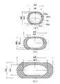
- the cross section of the insertion tube portion viewed from the direction orthogonal to the central axis in a predetermined region of the peripheral edge portion on the base end portion side opposite to the tip end portion of the tip opening end surface is formed into a curved shape having a bulge in the outer direction.
- the curvature radius in the curved shape is set to be equal to or less than the curvature radius in the other region in the peripheral edge.
- the end opening end surface at the distal end portion of the insertion tube portion is an inclined surface inclined with respect to a plane orthogonal to the central axis of the insertion tube portion.
- the thickness of the insertion cylinder part in the peripheral part in the base end part side of a front end opening end surface tends to become the thinnest. If it does so, the risk that the said part will be damaged when an intraocular lens passes increases.
- tip opening end surface becomes thick to the very vicinity of an end surface part.
- the peripheral edge portion of the end opening end surface is a sharp edge shape by an outer peripheral taper shape
- the outer peripheral surface taper-shaped cross section viewed from the direction perpendicular to the central axis in the predetermined region at the peripheral edge on the base end side of the tip opening end surface is formed into a curved shape having a bulge in the outer direction.
- the radius of curvature in the curved shape may be smaller than the radius of curvature in other regions in the outer peripheral surface taper shape.
- the outer peripheral surface taper-shaped portion on the proximal end side of the distal end opening end surface The wall thickness tends to become even thinner. If it does so, when the intraocular lens passes the outer peripheral surface taper-shaped part, the danger that the said part will be damaged becomes high.
- the inclination angle of the distal end opening end surface with respect to the surface orthogonal to the central axis of the insertion tube portion is formed larger on the proximal end side than on the distal end side
- the radius of curvature in the predetermined region of the peripheral edge on the base end side of the tip opening end surface is: You may make it make it smaller than the curvature radius seen from the direction orthogonal to the central axis of the said insertion cylinder part in the front end part side from the base end part in the said front end opening end surface.
- the inclination shape is linear ( The case where the radius of curvature is infinite) and the case where the curve has a certain radius of curvature are conceivable.
- the radius of curvature of the outer peripheral surface taper shape of the peripheral edge portion on the proximal end side of the distal end opening end surface is from the direction orthogonal to the central axis of the insertion tube portion on the distal end side from the proximal end portion on the distal end opening end surface.
- the curved shape of the cross section in the predetermined region of the peripheral edge portion on the proximal end side of the distal end opening end surface is a shape that is continuous with the outer shape behind the proximal end portion in the insertion tube portion. Also good. If it does so, the shape which continues back from the peripheral part of the base end part side of the front-end
- the radius of curvature of the cross section in the predetermined region of the peripheral edge on the base end side of the tip opening end face may be a radius of 0.3 mm to 0.4 mm.
- At least a part of the shape on the distal end side than the proximal end portion of the distal end opening end surface viewed from a direction orthogonal to the central axis of the insertion cylinder portion is linear.
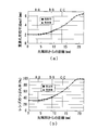
- the thickness in the predetermined region of the peripheral portion on the proximal end side of the distal opening end surface is such that the peripheral portion is more distal than the proximal end portion in the distal opening end surface as viewed from the direction perpendicular to the central axis of the insertion tube portion.
- the wall thickness may be increased in the range of 0.02 mm or more and 0.03 mm or less as compared with the case where the side shape is an extended shape.
- the present invention even when the insertion tube portion of the insertion device for the intraocular lens is further reduced in size, it is possible to suppress the inconvenience that the peripheral edge portion on the proximal end portion side of the distal end opening end surface is damaged when the intraocular lens passes. be able to.
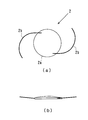
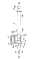
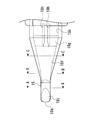
- FIG. 1 shows a schematic configuration of an intraocular lens insertion device 1 (hereinafter also simply referred to as an insertion device 1) in the present embodiment.
- 1A is a plan view
- FIG. 1B is a side view.
- the insertion instrument 1 is formed in a cylindrical shape having a substantially rectangular cross section, and one side is greatly opened (hereinafter, the side that is largely opened is referred to as a rear end part 10b), and the insertion cylinder is narrowed to another one side end.
- the nozzle main body 10 as an instrument main body provided with the nozzle part 15 as a part and the front-end
- the plunger 30 as an extrusion member which is inserted in the nozzle main body 10 and can reciprocate is provided.
- the direction from the front end 10a to the rear end 10b of the nozzle body 10 is the front-rear direction
- the vertical direction is the up-down direction
- the front-rear direction and the vertical direction are the left-right direction.
- a stage portion 12 for setting the intraocular lens 2 is provided on the rear end side of the nozzle portion 15 in the nozzle body 10.
- the stage portion 12 is configured such that the upper side of the nozzle body 10 (the front side perpendicular to the paper surface in FIG. 1A) is opened by opening the stage lid portion 13.
- a positioning member 50 is attached to the stage portion 12 from the lower side of the nozzle body 10 (the back side perpendicular to the paper surface in FIG. 1A). By this positioning member 50, the intraocular lens 2 is stably held in the stage portion 12 before use (during transportation).
- the intraocular lens 2 is set on the stage unit 12 in a state where the stage lid unit 13 is opened and the positioning member 50 is attached to the stage unit 12 at the time of manufacture.
- the user then removes the positioning member 50 with the stage lid 13 closed, and then pushes the plunger 30 into the distal end side of the nozzle body 10, thereby pressing the intraocular lens 2 with the plunger 30.
- the intraocular lens 2 is pushed out from the distal end portion 10a.
- the material of the nozzle body 10, the plunger 30, and the positioning member 50 in the insertion instrument 1 is formed of a resin such as polypropylene.
- Polypropylene is a material with a proven track record in medical equipment and high reliability such as chemical resistance.
- the stage portion 12 and the stage lid portion 13 are integrally formed.
- the stage lid portion 13 has the same longitudinal dimension as the stage portion 12.
- the stage lid portion 13 is connected by a thin plate-like connecting portion 14 formed by extending the side surface of the stage portion 12 to the stage lid portion 13 side.
- the connecting portion 14 is formed to be bendable at the center portion, and the stage lid portion 13 can be closed by overlapping the stage portion 12 from above by bending the connecting portion 14.
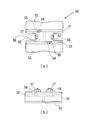
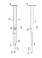
- FIG. 4 shows a schematic configuration of the positioning member 50.
- 4A shows a plan view
- FIG. 4B shows a side view.
- the positioning member 50 is configured as a separate body from the nozzle main body 10, and has a structure in which a pair of side wall portions 51, 51 are connected by a connecting portion 52. At the lower ends of the respective side wall portions 51, holding portions 53, 53 extending outward and extending are formed.
- the positioning member 50 is assembled from the lower side of the nozzle body 10, and the first placement portions 54 and 54 and the second placement portions 56 and 56 are fixed in a state of protruding from the set surface 12b.
- the bottom surface of the outer peripheral portion of the lens body 2a is placed on the upper surfaces of the first placement portions 54 and 54 and the second placement portions 56 and 56.
- the position of the lens body 2a is restricted in the front-rear and left-right directions by the first positioning portions 55, 55 and the second positioning portions 57, 57.
- a notch 31 c is formed at the tip of the action part 31.
- the notch 31 c is formed in a groove shape that opens upward in the action portion 31 and penetrates in the left-right direction.
- the end surface on the front end side of the cutout portion 31 c is formed as an inclined surface that goes upward as it goes to the front end side of the action portion 31.
- a claw portion 32 a that protrudes toward the upper side of the insertion portion 32 and can be moved up and down by the elasticity of the material of the plunger 30 is formed at the tip side of the insertion portion 32 in the front-rear direction center.
- the locking hole 10e provided in the thickness direction on the upper surface of the nozzle body 10 and the claw portion 32a engage with each other, whereby the nozzle in the initial state is engaged.
- a relative position between the main body 10 and the plunger 30 is determined.
- the claw portion 32a and the locking hole 10d are formed at the positions where the tip of the action portion 31 is located behind the lens body 2a of the intraocular lens 2 set on the stage portion 12 in the engaged state. It is set so that the notch 31c can support the support part 2b behind 2a from below.
- the tip 10a of the nozzle body 10 is inserted into an incision provided in the eye tissue.
- the press board part 33 of the plunger 30 is pushed in to the front end side of the nozzle main body 10 in the state.
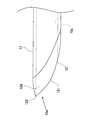
- FIG. 6 shows a detailed plan view of the vicinity of the tip 10 a of the nozzle body 10.
- the outer shape of the nozzle body 10 as a whole has a shape that gradually tapers from the stage portion 12 side toward the tip portion 10a.
- a reduced diameter portion 10f having a gradually reduced cross-sectional area is formed in the through hole 10c.
- the reduced diameter portion 10f is configured such that the cross-sectional area is reduced by reducing the width dimension of the bottom surface and the top surface toward the tip portion 10a side.
- the bottom surface of the rear end portion of the reduced diameter portion 10f is formed with an inclined surface 10g inclined so as to rise upward toward the distal end side, and a step is provided by the inclined surface 10g.
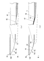
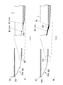
- a curvature radius R4 satisfying R4 ⁇ R2 is adopted in the sharp edge shape in the vicinity of the lower end portion 101 as shown in FIG.
- the curvature radius R4 also satisfies the relationship of R4 ⁇ R1 and R4 ⁇ R3.
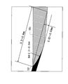
- the inclination angle of the straight opening 203 with respect to the M surface of the tip opening 20j is 75 degrees, and the thickness of the nozzle body 60 at the tip lower end 201 is very thin.
Landscapes
- Health & Medical Sciences (AREA)
- Ophthalmology & Optometry (AREA)
- Life Sciences & Earth Sciences (AREA)
- Animal Behavior & Ethology (AREA)
- Engineering & Computer Science (AREA)
- Biomedical Technology (AREA)
- Heart & Thoracic Surgery (AREA)
- Vascular Medicine (AREA)
- Veterinary Medicine (AREA)
- Public Health (AREA)
- General Health & Medical Sciences (AREA)
- Cardiology (AREA)
- Oral & Maxillofacial Surgery (AREA)
- Transplantation (AREA)
- Surgery (AREA)
- Nuclear Medicine, Radiotherapy & Molecular Imaging (AREA)
- Prostheses (AREA)
Priority Applications (3)
| Application Number | Priority Date | Filing Date | Title |
|---|---|---|---|
| US13/993,647 US10918519B2 (en) | 2010-12-14 | 2011-12-01 | Intraocular lens insertion apparatus |
| EP11848453.4A EP2641568B1 (en) | 2010-12-14 | 2011-12-01 | Intraocular lens insertion apparatus |
| ES11848453T ES2728903T3 (es) | 2010-12-14 | 2011-12-01 | Aparato de inserción de lente intraocular |
Applications Claiming Priority (2)
| Application Number | Priority Date | Filing Date | Title |
|---|---|---|---|
| JP2010278532A JP5658992B2 (ja) | 2010-12-14 | 2010-12-14 | 眼内レンズの挿入器具 |
| JP2010-278532 | 2010-12-14 |
Publications (1)
| Publication Number | Publication Date |
|---|---|
| WO2012081419A1 true WO2012081419A1 (ja) | 2012-06-21 |
Family
ID=46244528
Family Applications (1)
| Application Number | Title | Priority Date | Filing Date |
|---|---|---|---|
| PCT/JP2011/077867 Ceased WO2012081419A1 (ja) | 2010-12-14 | 2011-12-01 | 眼内レンズの挿入器具 |
Country Status (5)
| Country | Link |
|---|---|
| US (1) | US10918519B2 (enExample) |
| EP (1) | EP2641568B1 (enExample) |
| JP (1) | JP5658992B2 (enExample) |
| ES (1) | ES2728903T3 (enExample) |
| WO (1) | WO2012081419A1 (enExample) |
Cited By (2)
| Publication number | Priority date | Publication date | Assignee | Title |
|---|---|---|---|---|
| WO2014137925A1 (en) * | 2013-03-06 | 2014-09-12 | Abbott Medical Optics Inc. | Atraumatic iol insertion cartridge opening |
| EP3025677A4 (en) * | 2013-07-24 | 2017-03-15 | Kowa Company, Ltd. | Intraocular-lens-inserting instrument |
Families Citing this family (6)
| Publication number | Priority date | Publication date | Assignee | Title |
|---|---|---|---|---|
| JP2014226292A (ja) * | 2013-05-22 | 2014-12-08 | 日本ポリプロ株式会社 | 眼内レンズ挿入器具用部材 |
| USD735334S1 (en) * | 2013-09-18 | 2015-07-28 | Eye Care And Cure Asia Pte Ltd | Anterior capsulotomy device |
| PL3222247T3 (pl) * | 2014-11-19 | 2025-02-10 | Kowa Company Ltd. | Narzędzie do wprowadzania soczewki wewnątrzgałkowej |
| AU2016248520A1 (en) * | 2015-04-17 | 2017-12-07 | Kowa Company, Ltd. | Intraocular lens insertion instrument |
| DE102020109867B4 (de) * | 2020-04-08 | 2023-08-31 | Carl Zeiss Meditec Ag | Intraokularlinsen-Injektor mit spezifischer Einstechspitze einer Hohlnadel |
| JP7841289B2 (ja) * | 2022-03-02 | 2026-04-07 | 株式会社ニデック | 眼内レンズ挿入器具 |
Citations (3)
| Publication number | Priority date | Publication date | Assignee | Title |
|---|---|---|---|---|
| US20060264971A1 (en) * | 2005-05-18 | 2006-11-23 | Takayuki Akahoshi | Intraocular lens injection nozzle |
| JP2008307376A (ja) * | 2007-06-12 | 2008-12-25 | Alcon Inc | ウーン・アシステッド送達用のレンズ注入器用管腔チップ |
| JP2009160153A (ja) * | 2007-12-28 | 2009-07-23 | Menicon Co Ltd | 眼内レンズの挿入器具 |
Family Cites Families (7)
| Publication number | Priority date | Publication date | Assignee | Title |
|---|---|---|---|---|
| US6026A (en) * | 1849-01-09 | Cast-iron car-wheel | ||
| US7063681B1 (en) * | 1998-04-23 | 2006-06-20 | Alza Corporation | Trocar for inserting implants |
| JP2009028223A (ja) | 2007-07-26 | 2009-02-12 | Hoya Corp | 眼内レンズ挿入器具 |
| JP5255832B2 (ja) * | 2007-12-28 | 2013-08-07 | 興和株式会社 | 眼内レンズの挿入器具 |
| EP2085053B1 (en) | 2008-02-04 | 2011-05-04 | Nidek Co., Ltd. | Intraocular lens injection instrument |
| JP5209332B2 (ja) | 2008-02-04 | 2013-06-12 | 株式会社ニデック | 眼内レンズ挿入器具 |
| ES2723752T3 (es) | 2008-12-01 | 2019-08-30 | Kowa Co | Herramienta de inserción de lente intraocular |
-
2010
- 2010-12-14 JP JP2010278532A patent/JP5658992B2/ja active Active
-
2011
- 2011-12-01 ES ES11848453T patent/ES2728903T3/es active Active
- 2011-12-01 EP EP11848453.4A patent/EP2641568B1/en not_active Not-in-force
- 2011-12-01 US US13/993,647 patent/US10918519B2/en active Active
- 2011-12-01 WO PCT/JP2011/077867 patent/WO2012081419A1/ja not_active Ceased
Patent Citations (3)
| Publication number | Priority date | Publication date | Assignee | Title |
|---|---|---|---|---|
| US20060264971A1 (en) * | 2005-05-18 | 2006-11-23 | Takayuki Akahoshi | Intraocular lens injection nozzle |
| JP2008307376A (ja) * | 2007-06-12 | 2008-12-25 | Alcon Inc | ウーン・アシステッド送達用のレンズ注入器用管腔チップ |
| JP2009160153A (ja) * | 2007-12-28 | 2009-07-23 | Menicon Co Ltd | 眼内レンズの挿入器具 |
Cited By (7)
| Publication number | Priority date | Publication date | Assignee | Title |
|---|---|---|---|---|
| WO2014137925A1 (en) * | 2013-03-06 | 2014-09-12 | Abbott Medical Optics Inc. | Atraumatic iol insertion cartridge opening |
| US10265164B2 (en) | 2013-03-06 | 2019-04-23 | Johnson & Johnson Surgical Vision, Inc. | Atraumatic IOL insertion cartridge opening |
| US11000368B2 (en) | 2013-03-06 | 2021-05-11 | Johnson & Johnson Surgical Vision, Inc. | Atraumatic IOL insertion cartridge opening |
| US11717396B2 (en) | 2013-03-06 | 2023-08-08 | Johnson & Johnson Surgical Vision, Inc. | Atraumatic IOL insertion cartridge opening |
| US12053368B2 (en) | 2013-03-06 | 2024-08-06 | Johnson & Johnson Surgical Vision, Inc. | Atraumatic IOL insertion cartridge opening |
| EP3025677A4 (en) * | 2013-07-24 | 2017-03-15 | Kowa Company, Ltd. | Intraocular-lens-inserting instrument |
| US10213295B2 (en) | 2013-07-24 | 2019-02-26 | Kowa Company, Ltd. | Intraocular lens insertion apparatus |
Also Published As
| Publication number | Publication date |
|---|---|
| US10918519B2 (en) | 2021-02-16 |
| EP2641568A4 (en) | 2016-03-09 |
| JP2012125361A (ja) | 2012-07-05 |
| JP5658992B2 (ja) | 2015-01-28 |
| EP2641568A1 (en) | 2013-09-25 |
| ES2728903T3 (es) | 2019-10-29 |
| EP2641568B1 (en) | 2019-03-20 |
| US20130331853A1 (en) | 2013-12-12 |
Similar Documents
| Publication | Publication Date | Title |
|---|---|---|
| JP5658992B2 (ja) | 眼内レンズの挿入器具 | |
| JP6258865B2 (ja) | 眼内レンズの挿入器具 | |
| CN105636552B (zh) | 人工晶状体的插入仪器 | |
| JP5236637B2 (ja) | 眼内レンズ挿入器具及び眼内レンズ挿入装置 | |
| JP4707016B2 (ja) | 眼内レンズ挿入装置及びそのカートリッジ | |
| JP6099628B2 (ja) | 眼内レンズの挿入器具 | |
| JP5697962B2 (ja) | 眼内レンズの挿入器具 | |
| KR102131470B1 (ko) | 안내 렌즈 삽입 기구, 및 안내 렌즈 삽입 기구에 구비되는 위치 결정 부재 | |
| JP2009028223A (ja) | 眼内レンズ挿入器具 | |
| WO2016195095A1 (ja) | 眼内レンズ挿入器具 | |
| JP6958865B2 (ja) | トーリック眼内レンズおよび眼内レンズ挿入器具 | |
| JP2013244186A (ja) | 眼内レンズの挿入器具 | |
| JP5189357B2 (ja) | 眼内レンズの挿入器具 | |
| JP6057749B2 (ja) | 眼内レンズの挿入器具 | |
| KR20170137849A (ko) | 안내 렌즈 삽입 기구 | |
| US20200261214A1 (en) | Intraocular lens insertion apparatus | |
| JP2018198747A (ja) | 眼内レンズおよび眼内レンズ挿入器具 | |
| WO2025206267A1 (ja) | 眼内レンズ挿入器具 | |
| HK40027078A (en) | Intraocular lens insertion instrument |
Legal Events
| Date | Code | Title | Description |
|---|---|---|---|
| 121 | Ep: the epo has been informed by wipo that ep was designated in this application |
Ref document number: 11848453 Country of ref document: EP Kind code of ref document: A1 |
|
| NENP | Non-entry into the national phase |
Ref country code: DE |
|
| WWE | Wipo information: entry into national phase |
Ref document number: 2011848453 Country of ref document: EP |
|
| WWE | Wipo information: entry into national phase |
Ref document number: 13993647 Country of ref document: US |