WO2012081405A1 - 情報処理装置及びデータ管理システム - Google Patents
情報処理装置及びデータ管理システム Download PDFInfo
- Publication number
- WO2012081405A1 WO2012081405A1 PCT/JP2011/077746 JP2011077746W WO2012081405A1 WO 2012081405 A1 WO2012081405 A1 WO 2012081405A1 JP 2011077746 W JP2011077746 W JP 2011077746W WO 2012081405 A1 WO2012081405 A1 WO 2012081405A1
- Authority
- WO
- WIPO (PCT)
- Prior art keywords
- image data
- data management
- image
- management server
- storage unit
- Prior art date
- Legal status (The legal status is an assumption and is not a legal conclusion. Google has not performed a legal analysis and makes no representation as to the accuracy of the status listed.)
- Ceased
Links
Images







Classifications
-
- G—PHYSICS
- G16—INFORMATION AND COMMUNICATION TECHNOLOGY [ICT] SPECIALLY ADAPTED FOR SPECIFIC APPLICATION FIELDS
- G16H—HEALTHCARE INFORMATICS, i.e. INFORMATION AND COMMUNICATION TECHNOLOGY [ICT] SPECIALLY ADAPTED FOR THE HANDLING OR PROCESSING OF MEDICAL OR HEALTHCARE DATA
- G16H30/00—ICT specially adapted for the handling or processing of medical images
- G16H30/20—ICT specially adapted for the handling or processing of medical images for handling medical images, e.g. DICOM, HL7 or PACS
-
- G—PHYSICS
- G06—COMPUTING OR CALCULATING; COUNTING
- G06Q—INFORMATION AND COMMUNICATION TECHNOLOGY [ICT] SPECIALLY ADAPTED FOR ADMINISTRATIVE, COMMERCIAL, FINANCIAL, MANAGERIAL OR SUPERVISORY PURPOSES; SYSTEMS OR METHODS SPECIALLY ADAPTED FOR ADMINISTRATIVE, COMMERCIAL, FINANCIAL, MANAGERIAL OR SUPERVISORY PURPOSES, NOT OTHERWISE PROVIDED FOR
- G06Q10/00—Administration; Management
-
- G—PHYSICS
- G16—INFORMATION AND COMMUNICATION TECHNOLOGY [ICT] SPECIALLY ADAPTED FOR SPECIFIC APPLICATION FIELDS
- G16H—HEALTHCARE INFORMATICS, i.e. INFORMATION AND COMMUNICATION TECHNOLOGY [ICT] SPECIALLY ADAPTED FOR THE HANDLING OR PROCESSING OF MEDICAL OR HEALTHCARE DATA
- G16H40/00—ICT specially adapted for the management or administration of healthcare resources or facilities; ICT specially adapted for the management or operation of medical equipment or devices
- G16H40/20—ICT specially adapted for the management or administration of healthcare resources or facilities; ICT specially adapted for the management or operation of medical equipment or devices for the management or administration of healthcare resources or facilities, e.g. managing hospital staff or surgery rooms
-
- H—ELECTRICITY
- H04—ELECTRIC COMMUNICATION TECHNIQUE
- H04L—TRANSMISSION OF DIGITAL INFORMATION, e.g. TELEGRAPHIC COMMUNICATION
- H04L67/00—Network arrangements or protocols for supporting network services or applications
- H04L67/01—Protocols
- H04L67/12—Protocols specially adapted for proprietary or special-purpose networking environments, e.g. medical networks, sensor networks, networks in vehicles or remote metering networks
Definitions
- the present invention relates to an information processing apparatus and a data management system.
- a system for storing medical images taken by radiation or the like as digital data has been used.
- a medical image is stored in an image management server installed in a hospital, and an image is displayed by loading image data in the image management server at a client terminal.
- medical data such as medical image data taken at the medical facility is transmitted to the data center connected via the network, and the data center Has proposed a medical data storage system for accumulating and managing medical data (see Patent Document 1 and Patent Document 2).
- the present invention has been made in view of the above-described problems in the prior art, and an object thereof is to prevent a decrease in diagnostic efficiency.
- the invention described in claim 1 includes an acquisition unit that acquires image data from an inspection apparatus, and a first storage unit that temporarily stores image data acquired from the inspection apparatus. And transmitting the image data stored in the first storage means to the data management server so as to be stored in the second storage means included in the data management server connected so as to be capable of data communication via a communication network. Means for deleting image data stored in the first storage means from the first storage means when the predetermined condition is satisfied, the first storage means and the second storage The image data stored in the first storage means is obtained from the first storage means and the image data obtained from the first storage means is retrieved.
- An information processing apparatus comprising: display control means for displaying an image on the display means.
- the deletion unit when the deletion unit has passed a predetermined period after image data is stored in the first storage unit, The image data is deleted from the first storage means.
- the invention according to claim 3 is the information processing apparatus according to claim 1 or 2, wherein the processing performed by the information processing apparatus is performed according to an application program downloaded from the data management server, When an application program that is newer than the downloaded application program exists in the data management server, program update means is provided for downloading the new application program from the data management server.
- an information processing apparatus having a first storage means for temporarily storing image data acquired from the inspection apparatus, and a second for storing image data transmitted from the information processing apparatus. And a data management server connected to the data management server via a communication network so that data communication is possible, wherein the information processing apparatus stores the image data stored in the first storage unit, Transmitting means for transmitting to the data management server for storage in the second storage means; and image data stored in the first storage means when the predetermined condition is satisfied, for the first storage means The image data is searched for the deletion means for deleting from the first storage means and the second storage means, and the image data stored in the first storage means is searched.
- the image data is deleted from the first storage means.
- the processing performed by the information processing apparatus is performed according to an application program downloaded from the data management server
- the information processing apparatus includes program update means for downloading the new application program from the data management server when an application program newer than the downloaded application program exists in the data management server.
- a seventh aspect of the present invention is the data management system according to the sixth aspect, wherein the data management server determines the amount of image data stored in the second storage means and the number of times the application program is used. Based on this, the information processing apparatus includes a fee calculation means for calculating a fee related to the use of the data management system.
- the image data stored in the first storage unit is acquired from the first storage unit and is not stored in the first storage unit. Since the image data is acquired from the second storage means, the time required to display the image can be suppressed, and a decrease in diagnostic efficiency can be prevented.
- the latest application program can always be used.
- the fee can be calculated according to the use of the data management system in the information processing apparatus.
- FIG. 1 shows a system configuration of a data management system 100 in the present embodiment.
- the data management system 100 includes a data management server 1 installed in a local data center, an in-facility system 2A provided in a medical facility A, and an in-facility system provided in a medical facility B. 2B, and so on.
- the data management server 1, the in-facility system 2A, the in-facility system 2B,... are connected via a communication network N such as the Internet so that data communication is possible.
- the data management server 1 stores and manages image data of medical images generated at each medical facility.
- the data management server 1 provides a medical cooperation service between medical facilities, receives requests for inspections and interpretations in other in-facility systems from the in-facility systems 2A, 2B,. And the data of interpretation results.
- the in-facility system 2A includes an accepting device 3A, a terminal device 4A, an inspection device 5A, and a router 6A.
- the accepting device 3A, the terminal device 4A, and the router 6A are mutually connected by an in-facility network 7A such as a LAN (Local Area Network). It is configured to be connected for data communication.
- an in-facility network 7A such as a LAN (Local Area Network). It is configured to be connected for data communication.
- the terminal device 4A is connected to the data management server 1 via the communication network N by the router 6A so that data communication is possible.
- the in-facility system 2B includes an accepting device 3B, a terminal device 4B, an inspection device 5B, and a router 6B.
- the accepting device 3B, the terminal device 4B, and the router 6B are connected to each other via an in-facility network 7B such as a LAN.
- an in-facility network 7B such as a LAN.
- the terminal device 4B is connected to the data management server 1 via the communication network N by the router 6B so that data communication is possible.
- in-facility systems such as the in-facility systems 2A and 2B constituting the data management system 100 and the number of devices in each in-facility system are not particularly limited.
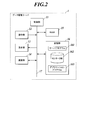
- FIG. 2 shows a functional configuration of the data management server 1.
- the data management server 1 includes a control unit 11, an operation unit 12, a display unit 13, a communication unit 14, a RAM 15, a storage unit 16, and the like, and each unit is connected by a bus 17. ing.
- the control unit 11 includes a CPU (Central Processing Unit) and the like, and comprehensively controls processing operations of each unit of the data management server 1. Specifically, the CPU reads out various processing programs stored in the storage unit 16 in accordance with an operation signal input from the operation unit 12 or an instruction signal received by the communication unit 14, and expands it in the RAM 15. Various processes are performed in cooperation with the program.
- CPU Central Processing Unit
- the operation unit 12 includes a keyboard having cursor keys, numeric input keys, various function keys, and the like, and a pointing device such as a mouse, and controls operation signals input by keyboard operations or mouse operations. 11 is output.
- the display unit 13 includes a monitor such as an LCD (Liquid Crystal Display), and displays various screens according to instructions of a display signal input from the control unit 11.
- a monitor such as an LCD (Liquid Crystal Display)
- LCD Liquid Crystal Display
- the communication unit 14 includes a network interface or the like, and transmits and receives data to and from an external device connected via the communication network N.
- the RAM 15 forms a work area that temporarily stores various programs, input or output data, parameters, and the like read from the storage unit 16 in various processes that are executed and controlled by the control unit 11.
- the storage unit 16 includes an HDD (Hard Disk Drive), a semiconductor non-volatile memory, and the like, and stores various processing programs, parameters and files necessary for executing the programs, and the like. Specifically, the storage unit 16 stores a server program 161, a center DB (DataBase) 162, an application program 163, and the like.
- HDD Hard Disk Drive
- the storage unit 16 stores a server program 161, a center DB (DataBase) 162, an application program 163, and the like.
- the server program 161 is a program for executing data management processing in the data management server 1, processing for providing the application program 163 and medical cooperation service, fee calculation processing (see FIG. 14), and the like.
- the center DB 162 includes a facility information table T1 (see FIG. 3) and an image information table T2 (see FIG. 4). Further, the center DB 162 stores image data transmitted from the terminal devices 4A, 4B,... Of each medical facility A, B,.
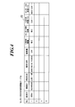
- FIG. 3 is an example of the facility information table T1 in the center DB 162.
- the facility information table T1 information related to medical facilities in the data management system 100 is stored.
- the facility information table T1 includes, for each medical facility, a facility ID, a facility PW (PassWord), a user ID, a user PW, a facility name, a user name, a used service type, a used device name, a device number No. , Software use count, data storage capacity, cooperation service use count, billing status, use stop flag are stored.
- the facility ID and the facility PW are identification information and a password determined for each medical facility.
- the user ID and the user PW are identification information and a password determined for each user.
- the service type used is information indicating the type of billing when using the data management system 100.
- Equipment name and equipment No. Are the device names and device numbers of the inspection devices 5A, 5B,... Used in each medical facility.
- the software use count is the number of times (monthly, cumulative, etc.) that software (an application program 461 described later) is used in each medical facility.
- the data storage capacity is the data capacity (monthly, cumulative, etc.) of each medical facility stored in the center DB 162 of the storage unit 16.
- the number of times the cooperative service is used is the number of times (monthly, cumulative, etc.) that the cooperative service (examination request or interpretation request to other medical facilities) is used in each medical facility.
- the billing status is information indicating whether or not a fee has been paid from each medical facility. As for the billing status, it is possible to acquire information from another system (sales distribution system, etc.) of the service provider.
- the use stop flag is a flag for designating whether or not to stop using the data management system 100 at each medical facility.
- FIG. 4 is an example of the image information table T2 in the center DB 162.
- the image information table T2 is prepared for each medical facility, and the image information table T2 stores information related to images related to examinations performed at each medical facility. Specifically, the patient information, examination ID, patient name, examination date, image type, primary DB existence, center DB existence, primary DB storage path, center DB storage path are stored in the image information table T2. .
- the patient ID is patient identification information in the medical facility.
- the inspection ID is identification information of the inspection.
- the patient name is the name of the patient.
- the inspection date is the date when the inspection was performed.
- the image type is information indicating the type of image, and includes CR (Computed Radiography), CT (Computed Tomography), MRI (Magnetic Resonance Imaging), and the like.
- the presence or absence of the primary DB is information indicating whether or not the image data generated by the examination is stored in the primary DB 462 (see FIG. 5) of each medical facility.
- the presence / absence of the center DB is information indicating whether or not the image data generated by the inspection is stored in the center DB 162.
- the primary DB storage path is information indicating a storage location of image data when image data generated by the examination is stored in the primary DB 462 (see FIG. 5) of each medical facility.
- the center DB storage path is information indicating a storage location of image data when image data generated by inspection is stored in the center DB 162.
- the application program 163 is a program for the terminal devices 4A, 4B,... Of the in-facility systems 2A, 2B,... To be downloaded, and is replaced with a new program every time the version is upgraded.
- the application program 163 provides the terminal devices 4A, 4B,... With a list display function, a viewer function, an image processing function such as enlargement / reduction / rotation, a measurement function, and an image output function to film / paper / media. It is a program for realizing.
- the control unit 11 uses the communication unit 14 to transmit image data from the terminal devices 4A, 4B,... And accompanying information (patient ID, examination ID, patient name, examination date, image type, primary DB storage path). Etc.). Then, the control unit 11 stores the received image data in the center DB 162 of the storage unit 16 and receives the accompanying information (patient ID, examination ID, patient name, examination date, image type, primary DB storage path) Etc.) is added to the image information table T2. Further, the control unit 11 sets the “existence of primary DB” of the corresponding examination in the image information table T2 to “present”, sets “presence / absence of center DB” to “present”, and sets the “center DB storage path” in the center DB 162.
- the control unit 11 controls the communication unit 14 to notify the fact that the image data is stored in the center DB 162 and the storage location of the image data in the center DB 162, the terminal devices 4A, 4B, ... to be transmitted. Further, the controller 11 stores “data storage” for the medical facility in which the facility information table T1 is inspected based on the data amount of the newly stored image data in accordance with the image data being stored in the center DB 162. Update "Capacity".
- the control unit 11 corresponds to a case where the communication unit 14 receives a notification that the image data has been deleted from the primary DB 462 (see FIG. 5) from the terminal devices 4A, 4B,.
- the image information table T2 of the medical facility “presence / absence of primary DB” of the corresponding examination is changed to “none”, and the storage destination of the image data in the primary DB 462 is deleted from “primary DB storage path”.
- the control unit 11 controls the communication unit 14 to control the terminal devices 4A, 4B,. .. Are transmitted with the application program 163 stored in the storage unit 16.
- the control unit 11 receives an inspection request or interpretation request from each medical facility in the data management system 100 to another medical facility, and notifies the other medical facility of the inspection request or interpretation request. In addition, the control unit 11 acquires examination data related to the examination performed in response to the examination request from the other medical facility, report data related to interpretation performed in response to the interpretation request, and the like, Provide to the facility.
- the control unit 11 uses the software from the terminal devices 4A, 4B,.
- the information is acquired, and the “software use count” for the corresponding medical facility in the facility information table T1 is updated.
- the control unit 11 receives the facility information when the cooperation service is used, such as when an inspection request or an interpretation request is received from the terminal devices 4A, 4B,.
- the “number of times of cooperation service use” for the corresponding medical facility in the table T1 is updated.
- the control part 11 calculates the charge which concerns on utilization of the data management system 100 of terminal device 4A, 4B, ... based on the facility information table T1. That is, the control unit 11 functions as a fee calculation unit. Specifically, the control unit 11 performs pay-per-use for each medical facility according to the “number of times of software use”, “data storage capacity”, and “number of times of cooperation service use” of the facility information table T1. It is also possible to set a flat fee with an unlimited “number of times of software use”, and charge for a certain amount of data storage capacity and “number of times of use of linked service” exceeding a predetermined upper limit.
- the receiving device 3A is a computer device including a control unit, an operation unit, a display unit, a communication unit, a RAM, a storage unit, and the like, and performs reception processing, accounting calculation, insurance score calculation, and the like of a patient who has come to the medical facility A. .
- the reception device 3A when the patient visits the medical facility A, in the reception device 3A, when the patient name and patient ID (patient identification information in the medical facility A) are input from the operation unit, the reception numbers are assigned in the order of reception, The reception number and patient name are associated with each other and stored in the storage unit.
- the terminal device 4A is an information processing device used when capturing image data from the inspection device 5A, when referring to an inspection image, or when requesting the data management server 1 to perform inspection or interpretation at another medical facility. is there.
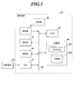
- FIG. 5 shows a functional configuration of the terminal device 4A.
- the terminal device 4A includes a control unit 41, an operation unit 42, a display unit 43, a communication unit 44, a RAM 45, a storage unit 46, a GW (GateWay) 47, and the like. Connected by a bus 48.
- the control unit 41 is composed of a CPU and the like, and comprehensively controls the processing operation of each unit of the terminal device 4A. Specifically, the CPU reads out various processing programs stored in the storage unit 46 in accordance with an operation signal input from the operation unit 42 or an instruction signal received by the communication unit 44, expands it in the RAM 45, Various processes are performed in cooperation with the program.
- the operation unit 42 includes a keyboard having cursor keys, numeric input keys, various function keys, and the like, and a pointing device such as a mouse.
- the control unit 42 controls operation signals input by keyboard operation or mouse operation. 41 is output.
- the display unit 43 includes a monitor such as an LCD, and displays various screens according to instructions of display signals input from the control unit 41.
- the communication unit 44 is configured by a network interface or the like, and transmits / receives data to / from an external device connected via the in-facility network 7A or the communication network N.
- the RAM 45 forms a work area that temporarily stores various programs, input or output data, parameters, and the like read from the storage unit 46 in various processes controlled by the control unit 41.
- the storage unit 46 is configured by an HDD, a semiconductor non-volatile memory, or the like, and stores various processing programs, parameters, files, and the like necessary for executing the programs. Specifically, the storage unit 46 stores an application program 461, a primary DB 462, and the like.
- the application program 461 is a program for executing processing related to the use of the data management system 100 in the terminal device 4A, and is downloaded from the data management server 1 (application program 163).
- the primary DB 462 includes a facility information table T3 (see FIG. 6) and an image information table T4 (see FIG. 7).
- the primary DB 462 temporarily stores image data acquired from the inspection apparatus 5A.
- FIG. 6 is an example of the facility information table T3 in the primary DB 462.
- the facility information table T3 information related to the medical facility A is stored.
- the facility information table T3 stores a facility ID, a facility PW, a user ID, a user PW, a facility name, and a user name.
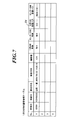
- FIG. 7 is an example of the image information table T4 in the primary DB 462.
- the image information table T4 stores information related to images related to examinations performed at the medical facility A.
- the image information table T4 includes the patient ID, the examination ID, the patient name, the examination date, the image type, the presence / absence of the primary DB, the presence / absence of the center DB, the primary DB storage path, and the center DB storage path of the medical facility A. Stored.
- GW 47 acquires image data and incidental information (patient ID, examination ID, patient name, examination date, image type, etc.) of the image data from the examination apparatus 5A. That is, the GW 47 functions as an acquisition unit.
- the supplementary information may be input from the operation unit 42 or may be received from the outside by the communication unit 44.
- the control unit 41 stores the image data acquired from the inspection device 5A in the primary DB 462 of the storage unit 46, and accompanying information (patient ID, inspection ID, patient name, inspection date and time, image acquired from the inspection device 5A) New records are added to the image information table T4 based on the seeds. Further, the control unit 11 sets “existence” to “existence” of the corresponding examination in the image information table T4, sets “existence” of the center DB to “not”, and sets the primary DB 462 to “primary DB storage path”. The image data storage destination is added, and the “center DB storage path” is blank.
- the control unit 41 controls the communication unit 44 to store the image data stored in the primary DB 462 of the storage unit 46 in the center DB 162 included in the data management server 1. , Patient name, examination date and time, image type, primary DB storage path, and the like).
- the control unit 41 corresponds to the image information table T4.
- the “center DB presence / absence” of the inspection is changed to “present”, and the storage destination of the image data in the center DB 162 is added to the “center DB storage path”.
- the control unit 41 deletes the image data stored in the primary DB 462 of the storage unit 46 from the primary DB 462 when a predetermined condition is satisfied. That is, the control unit 41 functions as a deletion unit. Specifically, when the predetermined period (for example, one month, three months, etc.) has elapsed since the image data was stored in the primary DB 462 of the storage unit 46, the control unit 41 performs the image data Are deleted from the primary DB 462.
- the predetermined period it is desirable to set a period in which normal image data is considered to be referred to in the in-facility system 2A.
- control unit 41 changes “presence / absence of primary DB” in the image information table T4 to “none” for the examination from which the image data has been deleted, and changes the image data in the primary DB 462 from “primary DB storage path”. Delete the storage location. Further, the control unit 41 controls the communication unit 44 to transmit a notification that the image data has been deleted from the primary DB 462 to the data management server 1.
- the control unit 41 searches the primary DB 462 and the center DB 162 for image data, acquires the image data stored in the primary DB 462 from the primary DB 462, and acquires the image data acquired from the primary DB 462.
- the image is displayed on the display unit 43 based on the image data, the image data not stored in the primary DB 462 is acquired from the center DB 162, and the image is displayed on the display unit 43 based on the image data acquired from the center DB 162. That is, the control unit 41 functions as a display control unit.
- the control unit 41 stores the new application program 163 from the data management server 1. to download. That is, the control unit 41 functions as a program update unit. Specifically, the control unit 41 compares the version information of the application program 461 that has already been downloaded with the version information of the latest application program 163 that exists in the data management server 1, and the application that has already been downloaded. If the program 461 is not the latest version, the communication unit 44 is controlled to cause the data management server 1 to transmit an acquisition request for a new application program 163 via the communication network N. When the communication unit 44 receives a new application program 163 from the data management server 1 via the communication network N, the control unit 41 stores the application program 163 in the storage unit 46 as the application program 461.
- the inspection apparatus 5A captures an image of a patient's diagnosis target region as a subject, and digitally converts the captured image to generate a medical image.
- Examples of the inspection apparatus 5A include CR, CT, and MRI.
- the in-facility system 2B other than the in-facility system 2A has the same configuration as the in-facility system 2A, the description thereof is omitted. Further, since the terminal device 4B and the like have the same configuration as the terminal device 4A, the description thereof is omitted with reference to FIG.
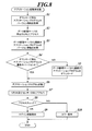
- FIG. 8 is a flowchart showing application startup processing executed by the terminal device 4A of the in-facility system 2A. This process is realized by software processing in cooperation with the control unit 41 and the application program 461 stored in the storage unit 46.
- the version information of the downloaded application program 461 stored in the storage unit 46 is acquired by the control unit 41 (step S1).
- control unit 41 accesses a predetermined URL (Uniform Resource Locator) of the data management server 1 via the communication network N (step S2). Specifically, the communication unit 44 is controlled by the control unit 41 and a predetermined URL is transmitted to the data management server 1.
- a predetermined URL Uniform Resource Locator
- the control unit 11 reads out the latest version information of the application program 163 stored in the storage unit 16, and the communication unit 14 The latest version information of the application program 163 is transmitted to the terminal device 4A via the communication network N.
- control unit 41 acquires the latest version information of the application program 163 from the data management server 1 via the communication unit 44 (step S3).
- the application program downloaded by the control unit 41 based on the version information of the downloaded application program 461 acquired in step S1 and the version information of the latest application program 163 acquired in step S3. It is determined whether or not 461 is the latest version (step S4). If the downloaded application program 461 is not the latest version (step S4; NO), that is, if an application program 163 newer than the already downloaded application program 461 exists in the data management server 1, the control unit 41 The latest application program 163 is downloaded from the data management server 1 (step S5). Specifically, the communication unit 44 is controlled by the control unit 41, and an acquisition request for a new application program 163 is transmitted to the data management server 1 via the communication network N. When the communication unit 44 receives a new application program 163 from the data management server 1 via the communication network N, the control unit 41 stores the application program 163 as the application program 461 in the storage unit 46. .
- step S4 when the downloaded application program 461 is the latest version (step S4; YES), or after step S5, the application program 461 is started by the control unit 41 (step S6).
- control unit 41 accesses the primary DB 462 of the storage unit 46 and the center DB 162 of the storage unit 16 of the data management server 1 (step S7).
- control unit 41 displays a login screen on the display unit 43 (step S9).
- step S8 when access to either the primary DB 462 or the center DB 162 fails (step S8; NG), the control unit 41 displays that an error has occurred on the display unit 43 (step S10). ). Thus, the application startup process ends.
- FIG. 9 is a flowchart showing image capture processing executed by the terminal device 4A of the in-facility system 2A. This process is realized by software processing in cooperation with the control unit 41 and the application program 461 stored in the storage unit 46.
- the user ID and the user PW are input by the operation from the operation unit 42, and login is performed (step S11).
- the facility information table T3 in the primary DB 462 is referred to by the control unit 41, and the use is permitted when the input user ID and user PW match the user ID and user PW in the facility information table T3.
- control unit 41 accesses the primary DB 462 of the storage unit 46 and the center DB 162 of the storage unit 16 of the data management server 1, and displays the information on the display unit 43 based on information that matches the search condition.
- a list screen is displayed (step S12).
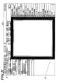
- FIG. 10 shows an example of the accepted patient list screen 431.
- the reception patient list screen 431 displays a list of patients who have completed reception processing on that day at the medical facility A.
- the control unit 41 acquires the patient ID and the reception number of the patient who completed the reception process on that day from the reception device 3A, and based on the acquired patient ID, the primary DB 462 of the storage unit 46, Corresponding patient information is acquired from the center DB 162 of the storage unit 16 of the data management server 1.
- the control unit 41 displays a received patient list screen 431 on the display unit 43 based on the acquired patient information.
- patient information display area 51 of the received patient list screen 431 patient information of the patient 52 selected on the list is displayed.
- a patient is selected by an operation from the operation unit 42 on the list screen displayed on the display unit 43 (step S13). For example, when any patient is selected on the accepted patient list screen 431 shown in FIG. 10 and the viewer screen display button 53 is pressed, the viewer 41 displays the viewer screen 432 shown in FIG. Then, the image capturing standby state is set (step S14).
- image data is acquired from the inspection apparatus 5A by the GW 47 (step S15), and the image data acquired from the inspection apparatus 5A is stored in the primary DB 462 of the storage unit 46 by the control unit 41 (step S16).
- the GW 47 obtains incidental information (patient ID, examination ID, patient name, examination date, image type, etc.) from the examination apparatus 5A.
- the control unit 41 stores incidental information (patient ID, examination ID, patient name, examination date and time, image type, etc.) in the image information table T4, and “existence of primary DB” in the image information table T4 is “present”.
- the “presence / absence of center DB” is “none”, the storage location of the image data in the primary DB 462 is added to the “primary DB storage path”, and the “center DB storage path” is blank.
- the control unit 41 displays an image on the display unit 43 based on the acquired image data (step S17). For example, in the viewer screen 432 shown in FIG. 11, when the CR capture button 61 is pressed by an operation from the operation unit 42, image data and incidental information are acquired from the inspection apparatus 5 ⁇ / b> A by the GW 47, and the control unit 41 An image is displayed in the image display area 62 of the viewer screen 432.
- step S18 when the image data is stored in the primary DB 462, the control unit 41 controls the communication unit 44, and the image data is stored in the data management server in order to back up to the center DB 162 of the storage unit 16 of the data management server 1. 1 (step S18).
- incidental information patient ID, examination ID, patient name, examination date and time, image type, primary DB storage path, etc.
- step S18 compares the image data stored in the primary DB 462 and the center DB 162 at all times (for example, at intervals of 3 seconds) and detects that new image data has been stored in the primary DB 462. This is realized by running a resident program that starts copying.
- the notification that the image data is stored in the center DB 162 and the storage location of the image data in the center DB 162 are received from the data management server 1 by the communication unit 44, the corresponding information in the image information table T4 is received by the control unit 41. “Presence / absence of center DB” of inspection is changed to “present”, and the storage destination of the image data in the center DB 162 is added to “center DB storage path”.
- the control unit 41 determines whether or not a predetermined period has elapsed since the image data was stored in the primary DB 462 (step S19). When a predetermined period has elapsed since the image data was stored in the primary DB 462 (step S19; YES), the control unit 41 deletes the image data from the primary DB 462 (step S20). Then, the control unit 41 changes “presence / absence of primary DB” of the corresponding examination in the image information table T4 to “none”, and deletes the storage destination of the image data in the primary DB 462 from “primary DB storage path”. Is done. In addition, the communication unit 44 is controlled by the control unit 41, and a notification that the image data has been deleted from the primary DB 462 is transmitted to the data management server 1. This completes the image capturing process.
- FIG. 12 is a flowchart showing image display processing executed by the terminal device 4A of the in-facility system 2A. This process is realized by software processing in cooperation with the control unit 41 and the application program 461 stored in the storage unit 46.
- the user ID and the user PW are input by the operation from the operation unit 42, and login is performed (step S21).
- control unit 41 accesses the primary DB 462 of the storage unit 46 and the center DB 162 of the storage unit 16 of the data management server 1, and displays the information on the display unit 43 based on information that matches the search condition.
- a list screen is displayed (step S22).
- a patient is selected by an operation from the operation unit 42 on the list screen displayed on the display unit 43 (step S23).
- the control unit 41 accesses the primary DB 462 of the storage unit 46 and the center DB 162 of the storage unit 16 of the data management server 1 (step S24).
- the control unit 41 determines whether or not the image data of the selected patient exists in the primary DB 462. Determination is made (step S26). Specifically, the control unit 41 refers to the “presence / absence of primary DB” column of each examination of the selected patient in the image information table T4 of the primary DB 462. If “exist”, the primary DB 462 is referred to. It is determined that there is no image data, and in the case of “none”, it is determined that there is no image data in the primary DB 462.
- control unit 41 refers to the “primary DB storage path” column of the corresponding examination in the image information table T4. Image data is acquired from the primary DB 462 (step S27).
- control unit 41 refers to the “Center DB storage path” column of the corresponding examination in the image information table T4. Then, image data is acquired from the center DB 162 (step S28). Specifically, the control unit 41 controls the communication unit 44 to transmit an image data acquisition request designated by the center DB storage path to the data management server 1 via the communication network N.
- the control unit 11 reads image data corresponding to the designated center DB storage path from the center DB 162, and the communication unit 14 transmits the read image data to the terminal device 4A. .
- the image data transmitted from the data management server 1 is received by the communication unit 44.
- step S27 or step S28 when there is other image data of the selected patient (step S29; YES), the process returns to step S26, and the process is repeated for the other image data.
- step S29 when there is no other image data of the selected patient (step S29; NO), the control unit 41 displays the viewer screen of the display unit 43 based on the one or more image data acquired. An image is displayed (step S30).
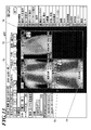
- FIG. 13 shows an example of the viewer screen 433.
- an image based on image data acquired from the primary DB 462 is displayed.
- Images based on image data acquired from the center DB 162 are displayed in the image display areas 72 and 73.
- center DB marks 74 and 75 are displayed so as to be distinguishable from the image based on the image data acquired from the primary DB 462.
- the data management server 1 when image data in the center DB 162 is acquired from the terminal device 4 ⁇ / b> A by performing data compression or resolution thinning processing on the image data in advance to generate a compressed image, first, The compressed image may be acquired and displayed.
- step S25 when there is no image data of the selected patient in either the primary DB 462 or the center DB 162 (step S25; NO), the process is ended as it is. This is the end of the image display process.
- FIG. 14 is a flowchart showing a charge calculation process executed by the data management server 1. This process is a process performed for each medical facility, and is realized by software processing in cooperation with the control unit 11 and the server program 161 stored in the storage unit 16.
- step S31 it is determined by the control unit 11 whether or not it is a charge calculation timing. For example, it is determined in advance to calculate a fee on a day determined every month.
- the control unit 11 When it is the charge calculation timing (step S31; YES), the control unit 11 obtains the software usage count, data storage capacity, and linked service usage count of the target medical facility from the facility information table T1 of the center DB 162. (Step S32). Based on the acquired software usage count, data storage capacity, and cooperative service usage count, the control unit 11 charges the data management system 100 in the target medical facility (terminal devices 4A, 4B,). Is calculated (step S33). For example, a fee is added as the number of times the software is used increases, a fee is added as the data storage capacity increases, and a fee is added as the number of times the cooperative service is used. However, the usage fee calculation method is not limited to this. This completes the charge calculation process.
- the image data stored in the primary DB 462 is acquired from the primary DB 462 and stored in the primary DB 462 in the terminal devices 4A, 4B,.
- Image data that has not been acquired image data that has been deleted from the primary DB 462 after a predetermined period has elapsed
- image data obtained by inspection is often referred to immediately after the inspection, so by leaving it in the primary DB 462 for a predetermined period, an image can be quickly displayed even in a high-speed communication environment. can do.
- the terminal devices 4A, 4B,... Automatically, when the application program 163 newer than the already downloaded application program 461 exists in the data management server 1, automatically sends the new application program 163 from the data management server 1. Therefore, the latest application program can be used at all times, and the user's trouble can be reduced.
- the data management server 1 can calculate a charge according to the use of the data management system 100 in the terminal devices 4A, 4B,.
- the image data is deleted from the primary DB 462.
- the data amount of the data stored in the storage unit 46 reaches the storage capacity of the storage unit 46 (or the data amount in the primary DB 462 becomes a predetermined storage capacity that can be used as the primary DB 462. If the image data has reached, the image data stored in the primary DB 462 may be deleted sequentially from the oldest image data.
- an HDD or a non-volatile memory is used as a computer-readable medium storing a program for executing each process
- a portable recording medium such as a CD-ROM
- a carrier wave may be applied as a medium for providing program data via a communication line.
- the information processing apparatus and data management system according to the present invention may be used in the medical field for managing image data acquired from an inspection apparatus.
Landscapes
- Engineering & Computer Science (AREA)
- Health & Medical Sciences (AREA)
- Business, Economics & Management (AREA)
- General Business, Economics & Management (AREA)
- Public Health (AREA)
- Epidemiology (AREA)
- General Health & Medical Sciences (AREA)
- Medical Informatics (AREA)
- Primary Health Care (AREA)
- Human Resources & Organizations (AREA)
- Strategic Management (AREA)
- Entrepreneurship & Innovation (AREA)
- Biomedical Technology (AREA)
- Marketing (AREA)
- Operations Research (AREA)
- Quality & Reliability (AREA)
- Economics (AREA)
- Tourism & Hospitality (AREA)
- Physics & Mathematics (AREA)
- General Physics & Mathematics (AREA)
- Theoretical Computer Science (AREA)
- Nuclear Medicine, Radiotherapy & Molecular Imaging (AREA)
- Radiology & Medical Imaging (AREA)
- Medical Treatment And Welfare Office Work (AREA)
Abstract
Description
図1に、本実施の形態におけるデータ管理システム100のシステム構成を示す。
図1に示すように、データ管理システム100は、地域のデータセンターに設置されたデータ管理サーバ1と、医療施設Aに設けられた施設内システム2Aと、医療施設Bに設けられた施設内システム2Bと、・・・を備えて構成されている。データ管理サーバ1、施設内システム2A、施設内システム2B、・・・は、インターネット等の通信ネットワークNを介してデータ通信可能に接続されている。
図2に、データ管理サーバ1の機能的構成を示す。
図2に示すように、データ管理サーバ1は、制御部11、操作部12、表示部13、通信部14、RAM15、記憶部16等を備えて構成されており、各部はバス17により接続されている。
ユーザID及びユーザPWは、ユーザ毎に定められた識別情報及びパスワードである。
使用サービス種は、データ管理システム100の利用における課金のタイプを示す情報である。
使用機器名及び機器号機No.は、各医療施設において使用されている検査装置5A,5B,・・・の機器名及び機器号機番号である。
ソフト使用回数は、各医療施設において、ソフトウェア(後述するアプリケーションプログラム461)が使用された回数(月毎、累積等)である。
データ保管容量は、記憶部16のセンターDB162に保管されている各医療施設のデータ容量(月毎、累積等)である。
連携サービス使用回数は、各医療施設において、連携サービス(他の医療施設への検査依頼や読影依頼等)が使用された回数(月毎、累積等)である。
課金状態は、各医療施設から料金が支払われているか否かを示す情報である。課金状態は、そのサービスプロバイダの別システム(販売物流システム等)から情報を取得することが可能となっている。
使用停止フラグは、各医療施設にデータ管理システム100の使用を停止させるか否かを指定するためのフラグである。
検査IDは、検査の識別情報である。
患者氏名は、患者の氏名である。
検査日時は、検査が行われた日時である。
画像種は、画像の種類を示す情報であり、CR(Computed Radiography)、CT(Computed Tomography)、MRI(Magnetic Resonance Imaging)等が挙げられる。
1次DB有無は、検査により生成された画像データが各医療施設の1次DB462(図5参照)内に保存されているか否かを示す情報である。
センターDB有無は、検査により生成された画像データがセンターDB162内に保存されているか否かを示す情報である。
1次DB保管パスは、検査により生成された画像データが各医療施設の1次DB462(図5参照)に保存されている場合の画像データの格納先を示す情報である。
センターDB保管パスは、検査により生成された画像データがセンターDB162に保存されている場合の画像データの格納先を示す情報である。
なお、「ソフト使用回数」を無制限として定額料金を設定し、「データ保管容量」及び「連携サービス使用回数」については予め定められた上限を超えた分だけ従量課金を行うこととしてもよい。
次に、施設内システム2Aを構成する各装置について説明する。
受付装置3Aは、制御部、操作部、表示部、通信部、RAM、記憶部等を備えたコンピュータ装置であり、医療施設Aに来院した患者の受付処理、会計計算、保険点数計算等を行う。患者が医療施設Aに来院した際に、受付装置3Aにおいて、操作部から患者氏名や患者ID(医療施設A内での患者の識別情報)が入力されると、受付順に受付番号が振られ、受付番号と患者氏名等が対応付けられて記憶部に記憶される。
図5に示すように、端末装置4Aは、制御部41、操作部42、表示部43、通信部44、RAM45、記憶部46、GW(GateWay)47等を備えて構成されており、各部はバス48により接続されている。
次に、データ管理システム100における動作について説明する。
図8は、施設内システム2Aの端末装置4Aにより実行されるアプリケーション起動時処理を示すフローチャートである。この処理は、制御部41と記憶部46に記憶されているアプリケーションプログラム461との協働によるソフトウェア処理によって実現される。
以上で、アプリケーション起動時処理が終了する。
図9は、施設内システム2Aの端末装置4Aにより実行される画像取り込み処理を示すフローチャートである。この処理は、制御部41と記憶部46に記憶されているアプリケーションプログラム461との協働によるソフトウェア処理によって実現される。
以上で、画像取り込み処理が終了する。
図12は、施設内システム2Aの端末装置4Aにより実行される画像表示処理を示すフローチャートである。この処理は、制御部41と記憶部46に記憶されているアプリケーションプログラム461との協働によるソフトウェア処理によって実現される。
端末装置4Aでは、通信部44により、データ管理サーバ1から送信された画像データが受信される。
また、データ管理サーバ1において、予め画像データに対してデータ圧縮又は解像度の間引き処理等を行って圧縮画像を生成しておき、端末装置4AからセンターDB162内の画像データを取得する際に、まず圧縮画像を取得して表示することとしてもよい。
以上で、画像表示処理が終了する。
図14は、データ管理サーバ1により実行される料金算出処理を示すフローチャートである。この処理は、医療施設それぞれに対して行われる処理であり、制御部11と記憶部16に記憶されているサーバプログラム161との協働によるソフトウェア処理によって実現される。
以上で、料金算出処理が終了する。
2A,2B 施設内システム
3A,3B 受付装置
4A,4B 端末装置
5A,5B 検査装置
6A,6B ルータ
7A,7B 施設内ネットワーク
11 制御部
12 操作部
13 表示部
14 通信部
15 RAM
16 記憶部
17 バス
41 制御部
42 操作部
43 表示部
44 通信部
45 RAM
46 記憶部
47 GW
48 バス
100 データ管理システム
161 サーバプログラム
162 センターDB
163 アプリケーションプログラム
461 アプリケーションプログラム
462 1次DB
N 通信ネットワーク
Claims (7)
- 検査装置から画像データを取得する取得手段と、
前記検査装置から取得された画像データを一時的に記憶する第1の記憶手段と、
前記第1の記憶手段に記憶された画像データを、通信ネットワークを介してデータ通信可能に接続されたデータ管理サーバが備える第2の記憶手段に記憶させるために前記データ管理サーバに送信する送信手段と、
所定の条件を満たした場合に、前記第1の記憶手段に記憶された画像データを前記第1の記憶手段から削除する削除手段と、
前記第1の記憶手段と前記第2の記憶手段とを対象として画像データの検索を行い、前記第1の記憶手段に記憶されている画像データについては前記第1の記憶手段から取得し当該第1の記憶手段から取得した画像データに基づいて表示手段に画像を表示させ、前記第1の記憶手段に記憶されていない画像データについては前記第2の記憶手段から取得し当該第2の記憶手段から取得した画像データに基づいて前記表示手段に画像を表示させる表示制御手段と、
を備える情報処理装置。 - 前記削除手段は、前記第1の記憶手段に画像データが記憶されてから予め定められた期間が経過した場合に、当該画像データを前記第1の記憶手段から削除する、
請求項1に記載の情報処理装置。 - 当該情報処理装置により行われる処理は、前記データ管理サーバからダウンロードされたアプリケーションプログラムに従って行われるものであり、
前記ダウンロードされたアプリケーションプログラムより新しいアプリケーションプログラムが前記データ管理サーバに存在する場合には、当該新しいアプリケーションプログラムを前記データ管理サーバからダウンロードするプログラム更新手段を備える、
請求項1又は2に記載の情報処理装置。 - 検査装置から取得された画像データを一時的に記憶する第1の記憶手段を有する情報処理装置と、当該情報処理装置から送信された画像データを記憶する第2の記憶手段を有するデータ管理サーバと、が通信ネットワークを介してデータ通信可能に接続されたデータ管理システムであって、
前記情報処理装置は、
前記第1の記憶手段に記憶された画像データを、前記第2の記憶手段に記憶させるために前記データ管理サーバに送信する送信手段と、
所定の条件を満たした場合に、前記第1の記憶手段に記憶された画像データを前記第1の記憶手段から削除する削除手段と、
前記第1の記憶手段と前記第2の記憶手段とを対象として画像データの検索を行い、前記第1の記憶手段に記憶されている画像データについては前記第1の記憶手段から取得し当該第1の記憶手段から取得した画像データに基づいて表示手段に画像を表示させ、前記第1の記憶手段に記憶されていない画像データについては前記第2の記憶手段から取得し当該第2の記憶手段から取得した画像データに基づいて前記表示手段に画像を表示させる表示制御手段と、
を備えるデータ管理システム。 - 前記削除手段は、前記第1の記憶手段に画像データが記憶されてから予め定められた期間が経過した場合に、当該画像データを前記第1の記憶手段から削除する、
請求項4に記載のデータ管理システム。 - 前記情報処理装置により行われる処理は、前記データ管理サーバからダウンロードされたアプリケーションプログラムに従って行われるものであり、
前記情報処理装置は、前記ダウンロードされたアプリケーションプログラムより新しいアプリケーションプログラムが前記データ管理サーバに存在する場合には、当該新しいアプリケーションプログラムを前記データ管理サーバからダウンロードするプログラム更新手段を備える、
請求項4又は5に記載のデータ管理システム。 - 前記データ管理サーバは、前記第2の記憶手段に記憶されている画像データのデータ量及び前記アプリケーションプログラムの使用回数に基づいて、前記情報処理装置における当該データ管理システムの利用に係る料金を算出する料金算出手段を備える、
請求項6に記載のデータ管理システム。
Priority Applications (2)
| Application Number | Priority Date | Filing Date | Title |
|---|---|---|---|
| US13/994,408 US20130268587A1 (en) | 2010-12-14 | 2011-12-01 | Information processing device and data management system |
| JP2012548722A JPWO2012081405A1 (ja) | 2010-12-14 | 2011-12-01 | 情報処理装置及びデータ管理システム |
Applications Claiming Priority (2)
| Application Number | Priority Date | Filing Date | Title |
|---|---|---|---|
| JP2010277582 | 2010-12-14 | ||
| JP2010-277582 | 2010-12-14 |
Publications (1)
| Publication Number | Publication Date |
|---|---|
| WO2012081405A1 true WO2012081405A1 (ja) | 2012-06-21 |
Family
ID=46244514
Family Applications (1)
| Application Number | Title | Priority Date | Filing Date |
|---|---|---|---|
| PCT/JP2011/077746 Ceased WO2012081405A1 (ja) | 2010-12-14 | 2011-12-01 | 情報処理装置及びデータ管理システム |
Country Status (3)
| Country | Link |
|---|---|
| US (1) | US20130268587A1 (ja) |
| JP (1) | JPWO2012081405A1 (ja) |
| WO (1) | WO2012081405A1 (ja) |
Cited By (3)
| Publication number | Priority date | Publication date | Assignee | Title |
|---|---|---|---|---|
| JP2016071557A (ja) * | 2014-09-29 | 2016-05-09 | 富士フイルム株式会社 | 診断支援プログラム開発促進装置、診断支援プログラム開発促進装置の作動方法および作動プログラム、並びに診断支援プログラム開発促進システム |
| JP2018165981A (ja) * | 2017-02-16 | 2018-10-25 | コニカ ミノルタ ヘルスケア アメリカズ, インコーポレイテッド | 医療画像及びデータのマルチロケーションエクスチェンジ |
| JP2020166431A (ja) * | 2019-03-28 | 2020-10-08 | 富士通株式会社 | 検索結果表示プログラム、検索結果表示方法および検索結果表示システム |
Families Citing this family (5)
| Publication number | Priority date | Publication date | Assignee | Title |
|---|---|---|---|---|
| US20130268559A1 (en) | 2011-07-13 | 2013-10-10 | Z124 | Virtual file system remote search |
| US9152404B2 (en) | 2011-07-13 | 2015-10-06 | Z124 | Remote device filter |
| US20130268703A1 (en) | 2011-09-27 | 2013-10-10 | Z124 | Rules based hierarchical data virtualization |
| JP6503884B2 (ja) * | 2015-05-22 | 2019-04-24 | 富士ゼロックス株式会社 | データ管理システム、情報管理装置、及びプログラム |
| CN112019952A (zh) * | 2020-09-04 | 2020-12-01 | 江苏爱尔数字科技有限公司 | —种摄像水表终端数据延时删除系统 |
Citations (3)
| Publication number | Priority date | Publication date | Assignee | Title |
|---|---|---|---|---|
| JPH0877332A (ja) * | 1994-09-09 | 1996-03-22 | Fujitsu Ltd | 画像情報管理装置 |
| JP2003281279A (ja) * | 2002-03-20 | 2003-10-03 | Yokogawa Electric Corp | 医療画像表示システム |
| JP2005301412A (ja) * | 2004-04-07 | 2005-10-27 | Fuji Photo Film Co Ltd | 医療データ管理方法及びシステム並びにそれに用いる端末 |
Family Cites Families (6)
| Publication number | Priority date | Publication date | Assignee | Title |
|---|---|---|---|---|
| US20030095648A1 (en) * | 1999-10-05 | 2003-05-22 | Lifecor, Inc. | Fault-tolerant remote reprogramming for a patient-worn medical device |
| US20020026384A1 (en) * | 2000-03-31 | 2002-02-28 | Matsushita Electric Industrial Co., Ltd. | Data storage, management, and delivery method |
| US8140481B2 (en) * | 2005-04-26 | 2012-03-20 | Kabushiki Kaisha Toshiba | Medical image filing system and medical image filing method |
| US7743023B2 (en) * | 2006-02-01 | 2010-06-22 | Microsoft Corporation | Scalable file replication and web-based access |
| US20080046378A1 (en) * | 2006-08-18 | 2008-02-21 | Siemens Aktiengesellschaft | System and method for selling software on a pay-per-use basis |
| US8554579B2 (en) * | 2008-10-13 | 2013-10-08 | Fht, Inc. | Management, reporting and benchmarking of medication preparation |
-
2011
- 2011-12-01 WO PCT/JP2011/077746 patent/WO2012081405A1/ja not_active Ceased
- 2011-12-01 US US13/994,408 patent/US20130268587A1/en not_active Abandoned
- 2011-12-01 JP JP2012548722A patent/JPWO2012081405A1/ja active Pending
Patent Citations (3)
| Publication number | Priority date | Publication date | Assignee | Title |
|---|---|---|---|---|
| JPH0877332A (ja) * | 1994-09-09 | 1996-03-22 | Fujitsu Ltd | 画像情報管理装置 |
| JP2003281279A (ja) * | 2002-03-20 | 2003-10-03 | Yokogawa Electric Corp | 医療画像表示システム |
| JP2005301412A (ja) * | 2004-04-07 | 2005-10-27 | Fuji Photo Film Co Ltd | 医療データ管理方法及びシステム並びにそれに用いる端末 |
Cited By (5)
| Publication number | Priority date | Publication date | Assignee | Title |
|---|---|---|---|---|
| JP2016071557A (ja) * | 2014-09-29 | 2016-05-09 | 富士フイルム株式会社 | 診断支援プログラム開発促進装置、診断支援プログラム開発促進装置の作動方法および作動プログラム、並びに診断支援プログラム開発促進システム |
| JP2018165981A (ja) * | 2017-02-16 | 2018-10-25 | コニカ ミノルタ ヘルスケア アメリカズ, インコーポレイテッド | 医療画像及びデータのマルチロケーションエクスチェンジ |
| US11265377B2 (en) | 2017-02-16 | 2022-03-01 | Konica Minolta Healthcare Americas, Inc. | Multi-location exchange of medical images and data |
| JP7068839B2 (ja) | 2017-02-16 | 2022-05-17 | コニカ ミノルタ ヘルスケア アメリカズ, インコーポレイテッド | 医療画像及びデータのマルチロケーションエクスチェンジ |
| JP2020166431A (ja) * | 2019-03-28 | 2020-10-08 | 富士通株式会社 | 検索結果表示プログラム、検索結果表示方法および検索結果表示システム |
Also Published As
| Publication number | Publication date |
|---|---|
| US20130268587A1 (en) | 2013-10-10 |
| JPWO2012081405A1 (ja) | 2014-05-22 |
Similar Documents
| Publication | Publication Date | Title |
|---|---|---|
| WO2012081405A1 (ja) | 情報処理装置及びデータ管理システム | |
| JP5040923B2 (ja) | 医用画像管理システム | |
| US20100017233A1 (en) | Medical image management system | |
| JP4868862B2 (ja) | 画像診断装置、医用システムおよびプロトコル管理方法 | |
| JP2018015079A (ja) | 画像管理装置、画像表示システム、及び画像表示方法 | |
| CN101395631B (zh) | 医学图像管理系统 | |
| US7383511B2 (en) | System, method and recording medium for medical image management | |
| JP6662317B2 (ja) | 医療連携システム | |
| JP2017151584A (ja) | 医療情報処理装置、プログラム及び医療情報管理システム | |
| JP2004194759A (ja) | 連携診断システム | |
| JP2008287653A (ja) | 医用画像管理装置及びプログラム | |
| JP5509831B2 (ja) | 医用画像管理システム及び医用画像管理方法 | |
| JP6881628B2 (ja) | 医療連携システム及び制御プログラム | |
| JP2011198310A (ja) | 医療連携システム | |
| US20180046760A1 (en) | Data management device and image display system | |
| JP6003595B2 (ja) | 医用画像システム | |
| JP2021177792A (ja) | 医用画像管理装置及びプログラム | |
| JP5741393B2 (ja) | 医用情報処理装置 | |
| JP5682316B2 (ja) | データ管理サーバ及び医療連携システム | |
| JP2013105350A (ja) | 電子カルテ作成システム | |
| JP2015125516A (ja) | 治験データ管理装置及び治験システム | |
| JP5825064B2 (ja) | 医用情報処理装置 | |
| JP2002269240A (ja) | 医療情報保管課金システムおよび方法並びにプログラム | |
| JP2017151583A (ja) | 画像送信装置、画像送信システム及び治験データ管理装置 | |
| JP2013105351A (ja) | 医用情報処理装置 |
Legal Events
| Date | Code | Title | Description |
|---|---|---|---|
| 121 | Ep: the epo has been informed by wipo that ep was designated in this application |
Ref document number: 11849832 Country of ref document: EP Kind code of ref document: A1 |
|
| ENP | Entry into the national phase |
Ref document number: 2012548722 Country of ref document: JP Kind code of ref document: A |
|
| NENP | Non-entry into the national phase |
Ref country code: DE |
|
| WWE | Wipo information: entry into national phase |
Ref document number: 13994408 Country of ref document: US |
|
| 122 | Ep: pct application non-entry in european phase |
Ref document number: 11849832 Country of ref document: EP Kind code of ref document: A1 |