WO2012081334A1 - 反射型表示装置用カラーフィルタ - Google Patents
反射型表示装置用カラーフィルタ Download PDFInfo
- Publication number
- WO2012081334A1 WO2012081334A1 PCT/JP2011/075615 JP2011075615W WO2012081334A1 WO 2012081334 A1 WO2012081334 A1 WO 2012081334A1 JP 2011075615 W JP2011075615 W JP 2011075615W WO 2012081334 A1 WO2012081334 A1 WO 2012081334A1
- Authority
- WO
- WIPO (PCT)
- Prior art keywords
- reflective display
- display device
- color filter
- white
- reflective
- Prior art date
- Legal status (The legal status is an assumption and is not a legal conclusion. Google has not performed a legal analysis and makes no representation as to the accuracy of the status listed.)
- Ceased
Links
Images


Classifications
-
- G—PHYSICS
- G02—OPTICS
- G02B—OPTICAL ELEMENTS, SYSTEMS OR APPARATUS
- G02B5/00—Optical elements other than lenses
- G02B5/20—Filters
- G02B5/201—Filters in the form of arrays
-
- G—PHYSICS
- G02—OPTICS
- G02B—OPTICAL ELEMENTS, SYSTEMS OR APPARATUS
- G02B5/00—Optical elements other than lenses
- G02B5/20—Filters
- G02B5/22—Absorbing filters
- G02B5/223—Absorbing filters containing organic substances, e.g. dyes, inks or pigments
-
- G—PHYSICS
- G02—OPTICS
- G02F—OPTICAL DEVICES OR ARRANGEMENTS FOR THE CONTROL OF LIGHT BY MODIFICATION OF THE OPTICAL PROPERTIES OF THE MEDIA OF THE ELEMENTS INVOLVED THEREIN; NON-LINEAR OPTICS; FREQUENCY-CHANGING OF LIGHT; OPTICAL LOGIC ELEMENTS; OPTICAL ANALOGUE/DIGITAL CONVERTERS
- G02F1/00—Devices or arrangements for the control of the intensity, colour, phase, polarisation or direction of light arriving from an independent light source, e.g. switching, gating or modulating; Non-linear optics
- G02F1/01—Devices or arrangements for the control of the intensity, colour, phase, polarisation or direction of light arriving from an independent light source, e.g. switching, gating or modulating; Non-linear optics for the control of the intensity, phase, polarisation or colour
- G02F1/13—Devices or arrangements for the control of the intensity, colour, phase, polarisation or direction of light arriving from an independent light source, e.g. switching, gating or modulating; Non-linear optics for the control of the intensity, phase, polarisation or colour based on liquid crystals, e.g. single liquid crystal display cells
- G02F1/133—Constructional arrangements; Operation of liquid crystal cells; Circuit arrangements
- G02F1/1333—Constructional arrangements; Manufacturing methods
- G02F1/1335—Structural association of cells with optical devices, e.g. polarisers or reflectors
- G02F1/133509—Filters, e.g. light shielding masks
- G02F1/133514—Colour filters
- G02F1/133516—Methods for their manufacture, e.g. printing, electro-deposition or photolithography
-
- G—PHYSICS
- G02—OPTICS
- G02F—OPTICAL DEVICES OR ARRANGEMENTS FOR THE CONTROL OF LIGHT BY MODIFICATION OF THE OPTICAL PROPERTIES OF THE MEDIA OF THE ELEMENTS INVOLVED THEREIN; NON-LINEAR OPTICS; FREQUENCY-CHANGING OF LIGHT; OPTICAL LOGIC ELEMENTS; OPTICAL ANALOGUE/DIGITAL CONVERTERS
- G02F1/00—Devices or arrangements for the control of the intensity, colour, phase, polarisation or direction of light arriving from an independent light source, e.g. switching, gating or modulating; Non-linear optics
- G02F1/01—Devices or arrangements for the control of the intensity, colour, phase, polarisation or direction of light arriving from an independent light source, e.g. switching, gating or modulating; Non-linear optics for the control of the intensity, phase, polarisation or colour
- G02F1/165—Devices or arrangements for the control of the intensity, colour, phase, polarisation or direction of light arriving from an independent light source, e.g. switching, gating or modulating; Non-linear optics for the control of the intensity, phase, polarisation or colour based on translational movement of particles in a fluid under the influence of an applied field
- G02F1/166—Devices or arrangements for the control of the intensity, colour, phase, polarisation or direction of light arriving from an independent light source, e.g. switching, gating or modulating; Non-linear optics for the control of the intensity, phase, polarisation or colour based on translational movement of particles in a fluid under the influence of an applied field characterised by the electro-optical or magneto-optical effect
- G02F1/167—Devices or arrangements for the control of the intensity, colour, phase, polarisation or direction of light arriving from an independent light source, e.g. switching, gating or modulating; Non-linear optics for the control of the intensity, phase, polarisation or colour based on translational movement of particles in a fluid under the influence of an applied field characterised by the electro-optical or magneto-optical effect by electrophoresis
Definitions
- the present invention relates to a color filter for a reflective display device that can impart high light utilization efficiency and a high NTSC ratio to a reflective display device, a reflective display device using the same, and electronic paper.
- Patent Document 1 electronic paper
- Patent Document 2 liquid crystal display device
- Such a display device is provided with a backlight on the back surface, and a transmissive display device that controls light emission by a display panel, and a reflective display that controls reflected light of ambient illumination (hereinafter also referred to as “ambient light”).
- ambient light reflected light of ambient illumination
- the reflection type display device has been applied because it has excellent characteristics such as low power consumption, no eye fatigue, and good visibility under direct sunlight.
- a color filter having a plurality of colored layers and a reflective display element capable of performing white display and black display are usually used in combination. It is done.
- a white color display is performed using a reflective display element to reflect ambient light and a desired color image is displayed by transmitting the reflected light through a color filter. It is.
- a light-shielding portion having a predetermined pattern is formed in a region other than the pixel portion in order to improve the contrast of the display image of the transmissive display device.
- the color filter having the above-described light-shielding portion is used in a reflective display device, the ambient light incident by the light-shielding portion of the color filter is absorbed, and as a result, the white display reflectance of the reflective display device is increased. As a result, the light utilization efficiency is reduced.
- a color filter provided with a white region that does not have a light-shielding portion and does not have a colored layer formed on the pixel portion has been developed.
- a reflective display device is proposed.
- the area ratio is too large, a decrease in the white display reflectance of the reflective display device can be suppressed, but since the NTSC ratio of the reflective display device is small, vivid color image display cannot be performed. There was a problem that there was a case. Further, until now, a guideline for designing a color filter having a white region in a reflective display device has not been clearly shown.
- the present inventors first determined that the ratio Y of the white display reflectance of the reflective display device to the white display reflectance of the reflective display element is constant in the reflective display device.
- the area ratio S of the white region to the area of the pixel portion of the color filter for the reflective display device is set to a predetermined value
- the knowledge indicates that the NTSC ratio of the reflective display device takes the maximum value. It was. Therefore, as a result of further earnest studies, the present inventors have designed the color filter so that the Y value of the reflective display device and the S value of the color filter are within a predetermined numerical range, thereby improving the light utilization efficiency. It has been found that a reflective display device having a high NTSC ratio and capable of displaying a clear color image can be obtained, and the present invention has been completed.
- the present invention provides a color filter for a reflective display device capable of imparting high light utilization efficiency and a high NTSC ratio to the reflective display device, a reflective display device using the same, and electronic paper.
- the main purpose is to provide a color filter for a reflective display device capable of imparting high light utilization efficiency and a high NTSC ratio to the reflective display device, a reflective display device using the same, and electronic paper. The main purpose.
- the present invention has been made to solve the above problems, and is a color filter for a reflective display device used in a reflective display device together with a reflective display element that performs white display and black display.
- a pixel portion comprising: a red colored layer formed on the transparent substrate; a colored layer having a green colored layer; and a blue colored layer; and a white region provided outside the colored layer forming region in which the colored layer is formed.
- the ratio of the white display reflectance of the reflective display device to the white display reflectance of the reflective display element, and the white region relative to the area of the pixel portion of the color filter for the reflective display device A color filter for a reflective display device, which is designed so that the area ratio satisfies the following relational expression (hereinafter may be simply referred to as a color filter).
- the color filter is designed to satisfy the above-described relational expression, high light utilization efficiency and clear color image display are performed on the reflective display device using the color filter. It is possible to provide a high NTSC ratio that is possible. Further, according to the present invention, the color filter capable of maximizing the display performance of the reflective display device such as the light utilization efficiency and the NTSC ratio in accordance with the reflective display device having a predetermined Y value has been described above. It becomes possible to design using the relational expression.
- the black display reflectance of the reflective display element is preferably in the range of 2.3% to 9.4%.
- the present invention provides a reflective display device having the above-described color filter and a reflective display element that performs white display and black display.
- the present invention has the above-described color filter, it is possible to provide a reflective display device having a high NTSC ratio capable of displaying a clear color image with high light utilization efficiency.
- the present invention also provides a color filter between the above-described color filter, a counter electrode substrate having a counter substrate and a counter electrode layer formed on the counter substrate, the color filter for a reflective display device, and the counter electrode substrate.
- an electronic paper comprising: a display medium layer disposed on the opposite side of the display medium layer; and a transparent electrode layer disposed on a side opposite to the counter electrode substrate side of the display medium layer.
- the present invention has the above-described color filter, it is possible to obtain an electronic paper having a high NTSC ratio capable of displaying a clear color image with high light use efficiency.
- the reflective display device using the color filter has a high light utilization efficiency and displays a vivid color image. It is possible to have an NTSC ratio capable of performing.
- the color filter of the present invention is used in a reflective display device together with a reflective display element that performs white display and black display, and includes a transparent substrate, a red colored layer, and a green colored layer formed on the transparent substrate. And a colored layer having a blue colored layer, and a pixel portion including a white region provided outside the colored layer forming region where the colored layer is formed, and the white display reflectance of the reflective display element.
- the ratio of the white display reflectance of the reflective display device to the color filter and the area ratio of the white region to the area of the pixel portion of the color filter for the reflective display device are designed to satisfy the following relational expression. It is characterized by being.
- the “white region” in the present invention is a region used as a pixel portion in the present invention, and refers to a region outside the colored layer forming region where the colored layer is formed, that is, a region where the colored layer is not formed. It is.
- a region that is not used as a pixel portion and that is not formed with a colored layer or the like is not included in the white region.
- the “pixel portion” in the present invention refers to an area used as an image display area when the color filter of the present invention is used in a reflective display device.
- the “white display reflectance of the reflective display element” refers to the reflectance of the reflective display element during white display.
- the “white display reflectance of the reflective display device” refers to the reflectance at the time of white display of the reflective display device, and the white display time when the color filter is arranged on the reflective display element. It refers to the reflectance.
- the white display reflectance of the reflective display element and the white display reflectance of the reflective display device according to the present invention are values measured in accordance with the standard configuration A of “Electronic Information Technology Industry Association Standard” EIAJ ED-2523. Shall be used.
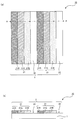
- FIG. 1A is a schematic plan view showing an example of the color filter of the present invention
- FIG. 1B is a cross-sectional view taken along line AA of FIG.
- the color filter 10 of the present invention includes a transparent substrate 1, a red colored layer 21R, a green colored layer 21G, and a blue colored layer formed on the transparent substrate 1.
- the pixel portion 2 includes the colored layer 21 having the layer 21 ⁇ / b> B and the white region 22 provided outside the colored layer forming region where the colored layer 21 is formed.
- FIGS. 1A and 1B an example in which the entire color filter 10 is used as the pixel unit 2 is shown. However, although not shown, for example, an area not used as the pixel unit on the outer periphery of the color filter is shown. It may be provided.
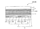
- FIG. 2 is a schematic sectional view showing an example of a reflective display device using the color filter of the present invention, and shows an example in which the reflective display device is electronic paper.
- the reflective display device 100 in which the color filter 10 of the present invention is used includes the color filter 10 and a reflective display element 30 that performs white display and black display.
- the display medium layer 4 is used as the reflective display element 30.
- the color filter 10 of the present invention includes a ratio Y of the white display reflectance of the reflective display device 100 to the white display reflectance of the reflective display element 30 and an area ratio of the white region 22 to the area of the pixel portion 2 of the color filter 10. S is designed to satisfy the above-described relational expression. Since FIG. 2 will be described in detail in the section “C. Electronic Paper” to be described later, description thereof is omitted here.
- the color filter having a white region has been proposed in order to more efficiently use the ambient light in the reflective display device.
- the area ratio of the white region of the filter is too large, a decrease in the white display reflectance of the reflective display device can be suppressed, but the NTSC ratio of the reflective display device becomes small, so that a vivid color image display is achieved. There was a problem that it may not be possible.
- the NTSC ratio of the reflective display device refers to the ratio of the color reproduction region of the red, green, and blue display reflectance actually measured by the reflective display device to the NTSC color reproduction region.
- the red display reflectance of the reflective display device refers to the reflectance when the reflective display element in the red region of the color filter is white and the others are black.
- the green and blue display reflectivities refer to the reflectivities when the color display of the color filter in the green and blue regions is white and the others are black.
- it is set as the value measured using the measuring method of the white display reflectance of a reflection type display element mentioned above, and the white display reflectance of a reflection type display apparatus, and the same measuring method. be able to.
- the present inventors have conducted intensive research in view of the above circumstances, and the relationship between the S value of the color filter and the NTSC ratio of the reflective display device when the Y value of the reflective display device is a constant value.
- the white region contributes to the light use efficiency of the reflective display device.
- the reflectance is considered to be large. Therefore, when the Y value of the reflective display device is a predetermined value, the concentration of the colorant in the color layer of each color of the color filter can be made higher than that in the case where the above-described white region is not included, As a result, it is considered that the NTSC value of the reflective display device can be set to a larger value compared to the case where the white area described above is not provided. Therefore, by increasing the value of S of the color filter, it is possible to increase the concentration of the colorant in the color layer of each color of the color filter, so that the NTSC ratio of the reflective display device can be improved. It is considered that.
- the S value of the color filter is too large, that is, if the S value of the color filter exceeds a predetermined value, the following problems can be considered. That is, when the S value of the color filter is large, the area of the colored layer for displaying each color is small.
- black display is performed on the reflective display elements facing the colored layer forming region and the white region of other colors.
- the S value of the color filter is too large, the influence of reflected light from the black display portion where color display is not performed becomes large, and the display by the colored layer of each color is lighter than the original color of the colored layer. Since it will be visually recognized, the NTSC ratio of the reflective display device is considered to be small.
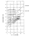
- the present inventors set the value of S of the color filter to a predetermined value so that the NTSC ratio of the reflective display device is maximized. From the fact that it was obtained as a knowledge, the reflection type display device according to a change in the S value of the color filter and the concentration of the colorant in the colored layer when the Y value of the reflection type display device is various. By examining the change in the NTSC ratio of the display device by simulation, as shown in FIG. 4, a reflective display device having an NTSC ratio with high light utilization efficiency and capable of displaying a clear color image is obtained. It was found that the Y value and S value of the reflective display device exist within the numerical range shown by the relational expression described above.
- FIG. 4 shows a reflection type obtained by changing the value of S of the color filter and the concentration of the colorant in the colored layer when the value of Y is changed to a value of 0.250 ⁇ Y ⁇ 0.750. It is a graph showing the change of the NTSC ratio of the display device, where the NTSC ratio of the reflective display device shows the maximum value, ⁇ , and the one where the NTSC ratio of the reflective display device does not show the maximum value is indicated by ⁇ . It is a thing. Since detailed simulation conditions and the like will be described in detail in the section of an embodiment described later, description thereof is omitted here.
- the relational expression indicates a numerical range that can be taken by the S value of the color filter and the Y value of the reflective display device in which the NTSC ratio of the reflective display device shows the maximum value in the graph of FIG. Is.
- straight line Y S + 0.360 indicating the upper limit of the relational expression described above has three (S, Y) coordinates, (0.375, 0.731), (0.143, 0.494), (0 .063, 0.415) to obtain an approximate curve.
- the color filter is designed so as to satisfy the above-described relational expression, high light utilization efficiency and a clear color image display are provided on the reflective display device using the color filter. It is possible to provide a high NTSC ratio that can be performed. Further, according to the present invention, the color filter capable of maximizing the display performance of the reflective display device such as the light utilization efficiency and the NTSC ratio in accordance with the reflective display device having a predetermined Y value has been described above. It becomes possible to design using the relational expression.
- Pixel part The pixel part in this invention is provided in the colored layer formation area in which the colored layer which has the red colored layer formed on the transparent substrate, the green colored layer, and the blue colored layer, and the said colored layer is formed. A white area.
- the value of the area ratio S of the white region to the area of the pixel portion of the present invention is not particularly limited as long as the above relational expression is satisfied. In the present invention, it is preferably in the range of 0.030 to 0.390, particularly preferably in the range of 0.250 to 0.380. This is because when the color filter of the present invention is used in the reflective display device, the display performance can be maximized by setting the value within the above numerical range.
- the colored layer in the present invention usually has three colors of a red colored layer, a green colored layer, and a blue colored layer, but the color layer is not limited to this, and colors other than the above-described three colors. It may have a colored layer.
- the colored layers of each color used in the present invention are usually formed in a pattern so that a plurality of colored layers and white areas are regularly arranged, but the pattern employed in the present invention is particularly limited. However, it can be appropriately selected depending on the application of the reflective display device in which the color filter of the present invention is used. Examples of such a pattern include a stripe type as shown in FIG. 1A, a mosaic type as shown in FIG. 5A, a triangle type as shown in FIG. 5B, and FIG. A 4-pixel arrangement type as shown in c) can be mentioned.
- the area of each colored layer is not particularly limited, and is appropriately adjusted according to the resolution of the reflective display device in which the color filter of the present invention is used.
- FIG. 5 is a pattern diagram showing an example of the pattern shape of the pixel portion in the color filter of the present invention. Further, reference numerals that are not described may be the same as those in FIG. 1, and thus description thereof is omitted here.
- Examples of the material for the colored layer include pigments and other colorants and photosensitive resins, and specifically, the same as those used for the colored layer of a general color filter. The description in is omitted.
- the thickness of the colored layer used in the present invention is not particularly limited as long as a good image display can be performed when the color filter of the present invention is used in a reflective display device. Can be set within a range of 0.5 ⁇ m to 3.0 ⁇ m.
- the method for forming the colored layer is not particularly limited as long as the colored layer having a desired thickness can be formed without color mixing.
- a generally known method such as a photolithography method or a printing method can be used.
- the concentration of the colorant contained in the colored layer is usually adjusted when the colored layer is formed. It is.
- Transparent substrate The transparent substrate used for this invention will not be specifically limited if the colored layer mentioned above can be formed on the said transparent substrate.
- Such a transparent substrate can be the same as a transparent substrate used for a general color filter.
- quartz glass, alkali-free glass, soda lime glass, Pyrex (registered trademark) glass, synthetic glass Examples thereof include a transparent rigid material having no flexibility such as a quartz plate, or a transparent flexible material having flexibility such as a transparent resin film and an optical resin plate.
- alkali-free glass is preferable in terms of reliability and cost.
- film thickness etc. of the said transparent substrate since it can be the same as that of the transparent substrate used for a general color filter, description here is abbreviate
- Color filter of the present invention is not particularly limited as long as it has the above-described transparent substrate and pixel portion, and a necessary configuration is appropriately added according to the type of reflective display device in which the color filter is used. Can be used.
- the transparent electrode layer used in the reflective display device may be formed on the color filter.
- the transparent electrode layer will be described.
- Transparent electrode layer The formation position of the transparent electrode layer used in the present invention is appropriately selected according to the type of the reflective display device used, and is on the side opposite to the pixel portion side of the transparent substrate. It may be formed on the surface, may be formed between the transparent substrate and the colored layer of each color, or may be formed on the colored layer. Moreover, the transparent electrode layer may be directly formed on the transparent substrate or the colored layer, or may be formed through another layer.
- the material of the transparent electrode layer used in the present invention is not particularly limited as long as it is a conductive material capable of forming the transparent electrode layer.
- a conductive material capable of forming the transparent electrode layer.
- ITO indium tin oxide
- IZO indium zinc oxide
- Conductive oxides such as tin oxide, zinc oxide, indium oxide and aluminum zinc oxide (AZO), metals such as Au and Ni
- conductive polymers such as polyaniline, polyacetylene, polyalkylthiophene derivatives, polysilane derivatives, etc.
- ITO is preferably used.
- the thickness of the transparent electrode layer used in the present invention is not particularly limited as long as it can function as a transparent electrode layer, but is preferably in the range of 15 nm to 200 nm. If the thickness of the transparent electrode layer is less than the above range, it is difficult to form the transparent electrode layer with a uniform thickness. If the thickness of the transparent electrode layer exceeds the above range, This is because the manufacturing cost increases because the time and materials used for film formation increase.
- the formation method of the transparent electrode layer used in the present invention is not particularly limited as long as the transparent electrode layer can be formed with a desired thickness.
- a method for forming such a transparent electrode layer a general electrode film forming method can be used.
- a PVD method such as a vacuum deposition method, a sputtering method, an ion plating method, a CVD method, a conductive paste
- coating is mentioned.
- the transparent electrode layer may be formed on the entire surface of the underlying layer or substrate, or may be formed in a pattern on the underlying layer or substrate surface.
- the color filter of the present invention can have, for example, an overcoat layer provided to protect the colored layer, in addition to the configuration described above. Since the overcoat layer can be the same as a general one, description thereof is omitted here.
- Reflective Display Device The color filter of the present invention is used for a reflective display device having a reflective display element capable of performing white display and black display.
- the display element used in the reflective display device is not particularly limited as long as it can perform white display and black display. If the black display reflectance of the reflective display element is low, the display element is low. Specifically, it is specifically preferable to be in the range of 2.3% to 9.4%, and more preferably in the range of 2.3% to 5.0%.
- the display performance of the reflective display device can be further improved.
- the “black display reflectance of the reflective display element” refers to the reflectance of the reflective display element during black display. Further, the black display reflectance of the reflective display element was measured using the same measurement method as the white display reflectance of the reflective display element and the white display reflectance of the reflective display device described above. Can be a value.
- the white display reflectance of the reflective display element when the color filter of the present invention is used in a reflective display device together with the reflective display element, it is possible to display a color image with a desired brightness.
- the degree is not particularly limited, and the higher the better, but specifically 30% or more, especially in the range of 30% to 50%, especially in the range of 40% to 50%. Is preferred. This is because when the white display reflectance of the reflective display element is less than the above range, the reflective display device may not function sufficiently.
- the reflective display device of the present invention includes the color filter described in the section “A. Color filter” described above, and a reflective display element that performs white display and black display.
- the present invention since the above-described color filter is provided, it is possible to provide a reflective display device having a high NTSC ratio that is highly efficient in use and capable of displaying a clear color image.
- Reflective Display Device The Y value of the reflective display device of the present invention, and the black display reflectance and the white display reflectance of the reflective display element used in the present invention are described in the above section “A. Color filter”. Since it can be the same as what was done, description here is abbreviate
- the reflective display device of the present invention is not particularly limited as long as it has the above-described color filter and a reflective display element that performs white display and black display. Specifically, the display medium layer And a reflective liquid crystal display device having a liquid crystal layer as a reflective display element.
- the reflective display device of the present invention is an electronic paper, it will be described in detail in the section “C.
- the reflective display device of the present invention is a reflective liquid crystal display device will be described.
- the reflective display device of the present invention is a reflective liquid crystal display device (hereinafter, the reflective liquid crystal display device may be simply referred to as a liquid crystal display device), usually, A counter electrode substrate for a liquid crystal display device having the above-described color filter, a counter substrate for a liquid crystal display device, and a counter electrode layer for a liquid crystal display device formed on the counter substrate for a liquid crystal display device, a color filter, and a liquid crystal display A liquid crystal layer formed by enclosing a liquid crystal material between the device and the counter electrode substrate.
- a liquid crystal layer is used as a reflective display element.
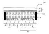
- FIG. 6 is a schematic sectional view showing another example of the reflective display device of the present invention, and shows an example in which the reflective display device is a liquid crystal display device.
- the liquid crystal display device 100 ′′ of the present invention includes a color filter 10, a counter substrate for liquid crystal display device 31 ′, and a counter electrode layer for liquid crystal display device 32 ′ formed on the counter substrate for liquid crystal display device 31 ′. And a liquid crystal layer 7 formed by enclosing a liquid crystal material between the color filter 10 and the counter electrode substrate 3 ′ for the liquid crystal display device.
- the liquid crystal layer 7 is used as the reflective display element 30. Since the color filter 10 in FIG. 6 can be the same as that in FIG. 1, the description thereof is omitted here.
- the liquid crystal layer 7 is usually sealed by disposing the sealing member 8 on the outer periphery of the color filter 10 and the counter electrode substrate 3 ′ for the liquid crystal display device. is there.
- each structure used for the liquid crystal display device of this invention is demonstrated.
- color filter used in the liquid crystal display device of the present invention can be the same as that described in the section “A. Color filter” described above, description thereof is omitted here.
- the configuration of the counter electrode substrate for the liquid crystal display device, the liquid crystal layer, the sealing member, and the like can be the same as that used in a general liquid crystal display device, and thus description thereof is omitted here.
- the black display reflectance and the white display reflectance of the liquid crystal layer are as long as a desired color image display can be performed when a color filter is attached to form a liquid crystal display device. It is not particularly limited.
- the preferable numerical ranges of the black display reflectance and the white display reflectance in the present invention are the preferable numerical ranges of the black display reflectance and the white display reflectance of the reflective display element described in the section “A. Color filter”. The description is omitted here.
- the electronic paper of the present invention includes the above-described color filter, a counter substrate having a counter substrate and a counter electrode layer formed on the counter substrate, the reflective display device color filter, and the counter electrode substrate. It has a display medium layer arranged in between, and a transparent electrode layer arranged on the opposite side to the counter electrode substrate side of the display medium layer. Note that the electronic paper of the present invention uses a display medium layer as a reflective display element.
- FIG. 2 is a schematic sectional view showing an example of the electronic paper of the present invention.
- the electronic paper 100 ′ includes a color filter 10, a counter substrate 31, a counter electrode substrate 3 having a counter electrode layer 32 formed on the counter substrate 31, the color filter 10, and
- the display medium layer 4 is disposed between the counter electrode substrates 3 and the transparent electrode layer 5 is disposed on the opposite side of the display medium layer 4 from the counter electrode substrate 3 side.
- an overcoat layer 6 is formed so as to cover the colored layer 21 of the color filter 10, and a transparent electrode layer 5 is further formed.
- the transparent electrode layer 5 and the display medium layer 4 of the color filter are formed.
- An example is shown in which the counter electrode substrate 3 side and the opposite side are arranged to face each other.
- reference numerals not described in the color filter in FIG. 2 can be the same as those in FIG.
- the color filter can be the same as that described in the above-mentioned section “A. Color filter”, and the description thereof is omitted here.
- Counter electrode substrate used in the present invention has a counter base material and a counter electrode layer formed on the counter base material.
- the counter electrode layer used in the present invention may be a pixel electrode layer formed so as to be orthogonal to the stripe pattern of the transparent electrode layer, and is connected to a plurality of TFT elements and the TFT elements. It may be a TFT electrode layer having a pixel electrode.
- the counter electrode layer can be the same as that used for a general electronic paper member, description thereof is omitted here.
- the counter substrate used in the present invention supports the counter electrode layer.
- a counter substrate is not particularly limited as long as it is generally used as a substrate such as electronic paper, and preferred examples include a glass plate and a plastic plate.
- Display medium layer The display medium layer used in the present invention is disposed on the counter electrode layer side of the counter electrode substrate described above, and has a display medium for performing white display and black display.
- the display medium layer used in the present invention is appropriately selected according to the electronic paper display method of the present invention.
- a display method of electronic paper known ones can be applied, for example, electrophoresis method, twist ball method, powder movement method (electronic powder fluid method, charged toner type method), liquid crystal display method, thermal method. (Coloring method, light scattering method), electrochromic method, electrowetting method, magnetophoresis method and the like.
- the electrophoresis method is preferably used. This is because this method is in a practical stage and is a particle movement type, and thus it is possible to obtain an electronic paper that is less dependent on viewing angle and excellent in responsiveness.
- the electrophoresis method uses an electrophoresis phenomenon in which charged particles dispersed in a solvent move between electrodes by an electric field.
- Examples of the electrophoresis method include a microcapsule method and a microcup method.
- the microcapsule method charged white particles and black particles and a transparent dispersion medium in which these particles are dispersed are encapsulated in a microcapsule made of a transparent resin, and an electric field is applied to the white particles and the black particles.
- the black and white display or gradation is expressed by moving up and down.
- a dispersion medium colored with a dye and charged white particles are arranged in a cell partitioned by cup-shaped depressions (microcups), and the white particles are moved up and down by applying an electric field. Thus, white or the color of the dispersion medium is displayed.
- the configuration, material, and formation method of the display medium layer used in the present invention can be the same as those used in general electronic paper of each display method.
- a display medium layer in the case where the electronic paper of the present invention is a microcapsule method will be described as an example.
- a display medium layer for example, a microcapsule in which a dispersion liquid composed of white particles, black particles, and a transparent dispersion medium is fixed with a binder resin can be used.
- transparent dispersion medium examples include alcohol solvents, various esters, ketones, aliphatic hydrocarbons, alicyclic hydrocarbons, aromatic hydrocarbons, halogenated hydrocarbons, carboxylates, and other various oils. Or a mixture of these with a surfactant or the like can be used.
- white particles for example, white pigments such as titanium dioxide, zinc white, and antimony trioxide can be used.
- black particles for example, black pigments such as aniline black, carbon black, and titanium black can be used.
- these pigments may be charged with electrolytes, surfactants, metal soaps, resins, rubbers, oils, varnishes, compound charge control agents, titanium-based coupling agents, aluminum-based coupling agents, A dispersant such as a silane coupling agent, a lubricant, a stabilizer and the like may be added.
- a material for forming the wall film of the microcapsule for example, a compound film such as a composite film of gum arabic / gelatin, urethane resin, urea resin, urea resin can be used.
- binder resin those having good affinity for the wall film of the microcapsule and having an insulating property can be used, and examples thereof include polyethylene, chlorinated polyethylene, ethylene-vinyl acetate copolymer, silicone resin and the like. Can do.
- Such a display medium layer can be formed, for example, by applying an ink obtained by dispersing microcapsules in a binder resin.
- the black display reflectance and the white display reflectance of the display medium layer in the present invention are not particularly limited as long as the reflective display device can perform a desired color image display. It is preferable to be within the numerical range of the black display reflectance and the white display reflectance of the reflective display element described in the section “.Color filter”.
- Transparent electrode layer The transparent electrode layer used for this invention is arrange
- a transparent electrode layer is not particularly limited as long as it can be disposed on the side opposite to the counter electrode substrate side of the display medium layer, and is formed on the display medium layer directly or via another layer. It may be formed on a color filter.
- the transparent electrode layer can be the same as that described in the section “A. Color filter” described above, and thus the description thereof is omitted here.
- the electronic paper of the present invention is not particularly limited as long as it has the above-described counter electrode substrate, display medium layer, and transparent electrode layer, and a necessary configuration can be appropriately selected and used. It is.
- Such a configuration includes an optical functional layer for improving the visibility of electronic paper, a surface protective layer for preventing scratches and dirt on the surface of electronic paper, and a barrier for protecting the display medium layer from moisture and oxygen. Examples thereof include a touch panel layer that imparts a layer and a function capable of inputting information by directly touching the screen to the electronic paper.
- any of the above-described layers is disposed on the pixel portion side of the color filter or on the side opposite to the pixel portion side.
- description here is abbreviate
- omitted is abbreviate
- the Y value of the electronic paper of the present invention can be the same as the Y value of the reflective display device described in the above-mentioned section “A. Color Filter”, so description thereof is omitted here. To do.
- the present invention is not limited to the above embodiment.
- the above-described embodiment is an exemplification, and the present invention has substantially the same configuration as the technical idea described in the claims of the present invention, and any device that exhibits the same function and effect is the present invention. It is included in the technical scope of the invention.
- Electrophoresis with PET film (Toyobo, product name: A4100, film thickness 125 ⁇ mt) as transparent substrate for color filter, and reflective display element with white display reflectance of 40.0% and black display reflectance of 4.6% Materials (E-ink Corporation) were prepared.
- a red colored layer, a green colored layer used for a color filter so that Y 0.500 (white display reflectance of electronic paper 20.0%)
- the reflectance of the reflective display device (electronic paper) and the reflective display element was measured in accordance with the standard configuration A of “Electronic Information Technology Industry Association Standard” EIAJ ED-2523.
- the illumination light source was D65.
- the NTSC ratio of electronic paper refers to the ratio of the color reproduction area of the red, green, and blue display reflectance of electronic paper measured under the above measurement conditions to the color reproduction area of the NTSC standard.
- the red display reflectance of electronic paper refers to the reflectance when the reflective display element in the red region of the color filter is white and the others are black.
- the green and blue display reflectivities refer to the reflectivities when the color display of the color filter in the green and blue regions is white and the others are black.
- a reflective display element is an electrophoretic material having a white display reflectance of 30% to 50% and a black display reflectance of 2.3% to 9.4%.
- concentration of the colorant in the red colored layer, the green colored layer, and the blue colored layer used in the color filter so that the Y value of the electronic paper is constant between 0.250 ⁇ Y ⁇ 0.750
- the NTSC ratios of various electronic papers with different color filter S values were obtained by simulation. The results are shown in FIG. In FIG. 4, the electronic paper whose NTSC ratio shows the maximum value is indicated by ⁇ , and the electronic paper that does not show the maximum value is indicated by ⁇ .
- Tables 1 to 3 show the S value of the color filter and the Y value of the electronic paper, in which the NTSC ratio of the electronic paper shows the maximum value.
- Table 1 shows a case where the white display reflectance of the reflective display element is 30%
- Table 2 shows a case where the white display reflectance of the reflective display element is 40%
- Table 3 shows a white display of the reflective display element. The case where the reflectance is 50% is shown.
- the black display reflectance in Tables 1 to 3 represents the black display reflectance of the reflective display element.
Landscapes
- Physics & Mathematics (AREA)
- General Physics & Mathematics (AREA)
- Optics & Photonics (AREA)
- Optical Filters (AREA)
- Electrochromic Elements, Electrophoresis, Or Variable Reflection Or Absorption Elements (AREA)
- Liquid Crystal (AREA)
Abstract
本発明は、反射型表示装置に、高い光利用効率および高いNTSC比を付与することが可能な反射型表示装置用カラーフィルタ、これを用いた反射型表示装置、および電子ペーパーを提供することを主目的とする。白表示および黒表示を行う反射型表示素子とともに反射型表示装置に用いられる反射型表示装置用カラーフィルタであって、透明基板と、透明基板上に形成された赤色着色層、緑色着色層、および青色着色層を有する着色層、並びに上記着色層が形成されている着色層形成領域外に設けられた白色領域を備える画素部と、を有し、上記反射型表示素子の白表示反射率に対する上記反射型表示装置の白表示反射率の割合と、上記反射型表示装置用カラーフィルタの上記画素部の面積に対する上記白色領域の面積比とが、下記に示す関係式を満たすように設計されたものであることを特徴とする反射型表示装置用カラーフィルタを提供することにより上記目的を達成する。 S+0.180<Y<S+0.360 (式中、Yは上記反射型表示素子の上記白表示反射率に対する上記反射型表示装置の上記白表示反射率の割合、Sは上記反射型表示装置用カラーフィルタの上記画素部の面積に対する上記白色領域の面積比である。)
Description
本発明は、反射型表示装置に高い光利用効率および高いNTSC比を付与することができる反射型表示装置用カラーフィルタ、これを用いた反射型表示装置、および電子ペーパーに関するものである。
近年、電子ペーパー(特許文献1)や液晶表示装置(特許文献2)等の各種のフラットタイプの表示装置の開発が進められている。このような表示装置は、背面にバックライトを設け、その発光を表示パネルで制御する透過型表示装置と、周囲の照明(以下、「環境光」とも言う)の反射光を制御する反射型表示装置とに大別される。また、このうち反射型表示装置は、低消費電力である、目が疲れない、および直射日光下での視認性が良い等の優れた特性を有することから応用が進められている。
上述した反射型表示装置において、カラー画像表示を行う場合は、通常、複数色の着色層を有するカラーフィルタと、白表示および黒表示を行うことが可能な反射型表示素子とが組み合わされて用いられる。また、このような反射型表示装置においては、反射型表示素子を用いて白表示を行うことによって環境光を反射させ、反射光をカラーフィルタに透過させることによって所望のカラー画像表示が行われるものである。
ここで、上述した透過型表示装置に用いられるカラーフィルタでは、透過型表示装置の表示画像のコントラストを向上させるため、画素部以外の領域に所定のパターンを有する遮光部が形成される。しかしながら、上述した遮光部を有するカラーフィルタを反射型表示装置に用いた場合は、カラーフィルタの遮光部によって入射した環境光が吸収されてしまい、その結果、反射型表示装置の白表示反射率が低下してしまうことから、光利用効率が低下してしまうといった問題があった。
上述した問題に対して、最近では反射型表示装置の光利用効率を向上させるために、遮光部を有さず、さらに画素部上に着色層が形成されていない白色領域を設けたカラーフィルタを備えた反射型表示装置が提案されている。
しかしながら、上述した反射型表示装置においては、カラーフィルタの画素部の面積に対する白色領域の面積比率と反射型表示装置のNTSC比との調整を行うことが困難であり、例えばカラーフィルタの白色領域の面積比率が大きすぎる場合は、反射型表示装置の白表示反射率の低下を抑制することはできるものの、反射型表示装置のNTSC比は小さくなることから、鮮やかなカラー画像表示を行うことができない場合があるといった問題があった。
また今まで、反射型表示装置において、白色領域を設けたカラーフィルタを設計するに際しての指針は明確に示されていない。
しかしながら、上述した反射型表示装置においては、カラーフィルタの画素部の面積に対する白色領域の面積比率と反射型表示装置のNTSC比との調整を行うことが困難であり、例えばカラーフィルタの白色領域の面積比率が大きすぎる場合は、反射型表示装置の白表示反射率の低下を抑制することはできるものの、反射型表示装置のNTSC比は小さくなることから、鮮やかなカラー画像表示を行うことができない場合があるといった問題があった。
また今まで、反射型表示装置において、白色領域を設けたカラーフィルタを設計するに際しての指針は明確に示されていない。
本発明者らは、上記実情に鑑みて鋭意研究を行った結果、まず反射型表示装置において、反射型表示素子の白表示反射率に対する反射型表示装置の白表示反射率の割合Yを一定の値とした場合、反射型表示装置用カラーフィルタの画素部の面積に対する白色領域の面積比Sを所定の値としたときに、反射型表示装置のNTSC比が最大値をとることを知見として得た。そこで、本発明者らはさらに鋭意研究を重ねた結果、反射型表示装置のYの値およびカラーフィルタのSの値が所定の数値範囲となるようにカラーフィルタを設計することにより、光利用効率が高く、かつ鮮明なカラー画像表示を行うことが可能なNTSC比を有する反射型表示装置を得られることを見出し、本発明を完成させるに至ったのである。
すなわち、本発明は、反射型表示装置に高い光利用効率および高いNTSC比を付与することが可能な反射型表示装置用カラーフィルタ、これを用いた反射型表示装置、および電子ペーパーを提供することを主目的とする。
本発明は、上記課題を解決するためになされたものであり、白表示および黒表示を行う反射型表示素子とともに反射型表示装置に用いられる反射型表示装置用カラーフィルタであって、透明基板と、上記透明基板上に形成された赤色着色層、緑色着色層、および青色着色層を有する着色層、並びに上記着色層が形成されている着色層形成領域外に設けられた白色領域を備える画素部と、を有し、上記反射型表示素子の白表示反射率に対する上記反射型表示装置の白表示反射率の割合と、上記反射型表示装置用カラーフィルタの上記画素部の面積に対する上記白色領域の面積比とが、下記に示す関係式を満たすように設計されたものであることを特徴とする反射型表示装置用カラーフィルタ(以下、単にカラーフィルタと称する場合がある。)を提供する。
S+0.180<Y<S+0.360
(式中、Yは上記反射型表示素子の上記白表示反射率に対する上記反射型表示装置の上記白表示反射率の割合、Sは上記反射型表示装置用カラーフィルタの上記画素部の面積に対する上記白色領域の面積比である。)
S+0.180<Y<S+0.360
(式中、Yは上記反射型表示素子の上記白表示反射率に対する上記反射型表示装置の上記白表示反射率の割合、Sは上記反射型表示装置用カラーフィルタの上記画素部の面積に対する上記白色領域の面積比である。)
本発明によれば、カラーフィルタが上述した関係式を満たすように設計されたものであることから、上記カラーフィルタを用いた反射型表示装置に、高い光利用効率および鮮明なカラー画像表示を行うことが可能な高いNTSC比を付与することが可能となる。
また、本発明によれば、所定のYの値を有する反射型表示装置に合わせて、光利用効率およびNTSC比といった反射型表示装置の表示性能を最大限引き出すことが可能なカラーフィルタを上述した関係式を用いて設計することが可能となる。
また、本発明によれば、所定のYの値を有する反射型表示装置に合わせて、光利用効率およびNTSC比といった反射型表示装置の表示性能を最大限引き出すことが可能なカラーフィルタを上述した関係式を用いて設計することが可能となる。
本発明においては、上記反射型表示素子の黒表示反射率が2.3%~9.4%の範囲内であることが好ましい。上記反射型表示素子とともに用いられるカラーフィルタとすることにより、反射型表示装置のYの値およびカラーフィルタのSの値をより好適に調整することが可能となる。
本発明は、上述したカラーフィルタ、および白表示および黒表示を行う反射型表示素子を有することを特徴とする反射型表示装置を提供する。
本発明は、上述したカラーフィルタを有することから、光利用効率が高く、かつ鮮明なカラー画像表示を行うことが可能な高いNTSC比を有する反射型表示装置とすることが可能となる。
また、本発明は、上述したカラーフィルタと、対向基材および上記対向基材上に形成された対向電極層を有する対向電極基板と、上記反射型表示装置用カラーフィルタおよび上記対向電極基板の間に配置された表示媒体層と、上記表示媒体層の対向電極基板側とは反対側に配置された透明電極層とを有することを特徴とする電子ペーパーを提供する。
本発明は、上述したカラーフィルタを有することから、光利用効率が高く、かつ鮮明なカラー画像表示を行うことが可能な高いNTSC比を有する電子ペーパーとすることが可能となる。
本発明のカラーフィルタは、上述した関係式を満たすように設計されたものであることにより、上記カラーフィルタを用いた反射型表示装置は、高い光利用効率を有し、かつ鮮やかなカラー画像表示を行うことが可能なNTSC比を有することが可能となるといった作用効果を奏する。
以下、本発明のカラーフィルタ、反射型表示装置、および電子ペーパーについて説明する。
A.カラーフィルタ
まず、本発明のカラーフィルタについて説明する。
まず、本発明のカラーフィルタについて説明する。
本発明のカラーフィルタは、白表示および黒表示を行う反射型表示素子とともに反射型表示装置に用いられるものであって、透明基板と、上記透明基板上に形成された赤色着色層、緑色着色層、および青色着色層を有する着色層、並びに上記着色層が形成されている着色層形成領域外に設けられた白色領域を備える画素部と、を有し、上記反射型表示素子の白表示反射率に対する上記反射型表示装置の白表示反射率の割合と、上記反射型表示装置用カラーフィルタの上記画素部の面積に対する上記白色領域の面積比とが、下記に示す関係式を満たすように設計されたものであることを特徴とするものである。
S+0.180<Y<S+0.360
(式中、Yは上記反射型表示素子の上記白表示反射率に対する上記反射型表示装置の上記白表示反射率の割合、Sは上記反射型表示装置用カラーフィルタの上記画素部の面積に対する上記白色領域の面積比である。)
S+0.180<Y<S+0.360
(式中、Yは上記反射型表示素子の上記白表示反射率に対する上記反射型表示装置の上記白表示反射率の割合、Sは上記反射型表示装置用カラーフィルタの上記画素部の面積に対する上記白色領域の面積比である。)
ここで、本発明における「白色領域」とは、本発明における画素部として用いられる領域であり、着色層が形成されている着色層形成領域外、すなわち着色層が形成されていない領域を指すものである。なお、本発明のカラーフィルタにおいて、画素部として用いられない領域であって、かつ着色層等が形成されていない領域については、白色領域には含まれないものとする。
また、本発明における「画素部」とは、本発明のカラーフィルタを反射型表示装置に用いた場合に、画像表示を行う領域として用いられる領域を指すものである。
また、本発明における「画素部」とは、本発明のカラーフィルタを反射型表示装置に用いた場合に、画像表示を行う領域として用いられる領域を指すものである。
また、ここで「反射型表示素子の白表示反射率」とは、反射型表示素子の白表示時の反射率を指すものである。
また、「反射型表示装置の白表示反射率」とは、反射型表示装置の白表示時の反射率を指すものであり、反射型表示素子にカラーフィルタを配置した状態での白表示時の反射率を指すものである。
なお、本発明における反射型表示素子の白表示反射率、および反射型表示装置の白表示反射率は、「電子情報技術産業協会規格」 EIAJ ED-2523の標準構成Aに則って測定された値を用いるものとする。
また、「反射型表示装置の白表示反射率」とは、反射型表示装置の白表示時の反射率を指すものであり、反射型表示素子にカラーフィルタを配置した状態での白表示時の反射率を指すものである。
なお、本発明における反射型表示素子の白表示反射率、および反射型表示装置の白表示反射率は、「電子情報技術産業協会規格」 EIAJ ED-2523の標準構成Aに則って測定された値を用いるものとする。
ここで、本発明のカラーフィルタを図を用いて説明する。図1(a)は、本発明のカラーフィルタの一例を示す概略平面図であり、図1(b)は、図1(a)のA-A線断面図である。図1(a)、(b)に例示されるように、本発明のカラーフィルタ10は、透明基板1と、透明基板1上に形成された赤色着色層21R、緑色着色層21G、および青色着色層21Bを有する着色層21、並びに着色層21が形成されている着色層形成領域外に設けられた白色領域22を備える画素部2と、を有するものである。なお、図1(a)、(b)においては、カラーフィルタ10全面が画素部2として用いられる例について示しているが、図示しないが、例えばカラーフィルタの外周に画素部として用いられない領域を設けてもよい。
また、図2は、本発明のカラーフィルタが用いられた反射型表示装置の一例を示す概略断面図であり、反射型表示装置が電子ペーパーである例について示している。
図2に例示するように、本発明のカラーフィルタ10が用いられる反射型表示装置100は、カラーフィルタ10と、白表示および黒表示を行う反射型表示素子30とを有するものである。なお、図2に示す反射型表示装置100(電子ペーパー100’)においては、表示媒体層4を反射型表示素子30として用いるものである。
本発明のカラーフィルタ10は、反射型表示素子30の白表示反射率に対する反射型表示装置100の白表示反射率の割合Yと、カラーフィルタ10の画素部2の面積に対する白色領域22の面積比Sとが、上述した関係式を満たすように設計されたことを特徴とするものである。
なお、図2については、後述する「C.電子ペーパー」の項で詳しく説明するため、ここでの記載は省略する。
図2に例示するように、本発明のカラーフィルタ10が用いられる反射型表示装置100は、カラーフィルタ10と、白表示および黒表示を行う反射型表示素子30とを有するものである。なお、図2に示す反射型表示装置100(電子ペーパー100’)においては、表示媒体層4を反射型表示素子30として用いるものである。
本発明のカラーフィルタ10は、反射型表示素子30の白表示反射率に対する反射型表示装置100の白表示反射率の割合Yと、カラーフィルタ10の画素部2の面積に対する白色領域22の面積比Sとが、上述した関係式を満たすように設計されたことを特徴とするものである。
なお、図2については、後述する「C.電子ペーパー」の項で詳しく説明するため、ここでの記載は省略する。
ここで、白色領域を有するカラーフィルタは、反射型表示装置において環境光をより効率よく利用するために提案されたものである。
しかしながら、上述したカラーフィルタを用いた反射型表示装置においては、カラーフィルタの画素部の面積に対する白色領域の面積比率と反射型表示装置のNTSC比との調整を行うことが困難であり、例えばカラーフィルタの白色領域の面積比率が大きすぎる場合は、反射型表示装置の白表示反射率の低下を抑制することはできるものの、反射型表示装置のNTSC比は小さくなることから、鮮やかなカラー画像表示を行うことができない場合があるといった問題があった。
また今まで、反射型表示装置において、白色領域を設けたカラーフィルタを設計するに際しての明確な指針については示されていなかった。
しかしながら、上述したカラーフィルタを用いた反射型表示装置においては、カラーフィルタの画素部の面積に対する白色領域の面積比率と反射型表示装置のNTSC比との調整を行うことが困難であり、例えばカラーフィルタの白色領域の面積比率が大きすぎる場合は、反射型表示装置の白表示反射率の低下を抑制することはできるものの、反射型表示装置のNTSC比は小さくなることから、鮮やかなカラー画像表示を行うことができない場合があるといった問題があった。
また今まで、反射型表示装置において、白色領域を設けたカラーフィルタを設計するに際しての明確な指針については示されていなかった。
なお、反射型表示装置のNTSC比とは、NTSC規格の色再現領域に対する、反射型表示装置の実測した赤、緑、青表示反射率の色再現領域の割合を指すものである。
反射型表示装置の赤表示反射率とは、カラーフィルタの赤色領域の反射型表示素子を白表示、その他を黒表示にした場合の反射率を指す。
緑、青表示反射率も同様に、それぞれ、カラーフィルタの緑、青色領域の反射型表示素子を白表示、その他を黒表示にした場合の反射率を指す。
なお、上述した各々の反射率については、上述した反射型表示素子の白表示反射率および反射型表示装置の白表示反射率の測定方法と、同様の測定方法を用いて測定された値とすることができる。
反射型表示装置の赤表示反射率とは、カラーフィルタの赤色領域の反射型表示素子を白表示、その他を黒表示にした場合の反射率を指す。
緑、青表示反射率も同様に、それぞれ、カラーフィルタの緑、青色領域の反射型表示素子を白表示、その他を黒表示にした場合の反射率を指す。
なお、上述した各々の反射率については、上述した反射型表示素子の白表示反射率および反射型表示装置の白表示反射率の測定方法と、同様の測定方法を用いて測定された値とすることができる。
そこで本発明者らは、上記実情に鑑みて鋭意研究を行い、反射型表示装置のYの値を一定の値とした場合のカラーフィルタのSの値と反射型表示装置のNTSC比との関係を調べた結果、図3のグラフに示すように、カラーフィルタのSの値を所定の値としたときに、反射型表示装置のNTSC比が最大値をとることを知見として得た。なお、図3のグラフは、Y=0.500としたときに、Sの値と反射型表示装置のNTSC比とを変化させた例について示している。なお、詳しい測定条件等については、後述する実施例の項で詳しく説明するため、ここでの説明は省略する。
ここで、反射型表示装置のYの値を一定とした場合、カラーフィルタのSの値を所定の値としたときに、反射型表示装置のNTSC比が最大値をとる理由については明らかではないが、次のように推測される。
まず、カラーフィルタの画素部が白色領域を有さない場合、すなわちS=0である場合、反射型表示装置の光利用効率に寄与する白色領域が存在しないことから、反射型表示装置が所定のYの値を示すためには、反射型表示装置の白表示反射率をカラーフィルタの各色の着色層中の着色剤の濃度を制限することによって調整する必要がある。そのため、反射型表示装置のNTSC比は小さな値を示すものと考えられる。
まず、カラーフィルタの画素部が白色領域を有さない場合、すなわちS=0である場合、反射型表示装置の光利用効率に寄与する白色領域が存在しないことから、反射型表示装置が所定のYの値を示すためには、反射型表示装置の白表示反射率をカラーフィルタの各色の着色層中の着色剤の濃度を制限することによって調整する必要がある。そのため、反射型表示装置のNTSC比は小さな値を示すものと考えられる。
一方、カラーフィルタの画素部に白色領域が存在する場合は、白色領域が反射型表示装置の光利用効率に寄与することから、白色領域を有さない場合に比べて反射型表示装置の白表示反射率は大きなものとなると考えられる。
よって反射型表示装置のY値が所定の値である場合、カラーフィルタの各色の着色層中の着色剤の濃度を上述した白色領域を有しない場合に比べて高いものとすることができ、その結果、反射型表示装置のNTSCの値を上述した白色領域を有しない場合に比べて大きな値とすることができるものと考えられる。
したがって、カラーフィルタのSの値を増やすことにより、カラーフィルタの各色の着色層中の着色剤の濃度を高くすることが可能となることから、反射型表示装置のNTSC比を向上させることが可能となるものと考えられる。
よって反射型表示装置のY値が所定の値である場合、カラーフィルタの各色の着色層中の着色剤の濃度を上述した白色領域を有しない場合に比べて高いものとすることができ、その結果、反射型表示装置のNTSCの値を上述した白色領域を有しない場合に比べて大きな値とすることができるものと考えられる。
したがって、カラーフィルタのSの値を増やすことにより、カラーフィルタの各色の着色層中の着色剤の濃度を高くすることが可能となることから、反射型表示装置のNTSC比を向上させることが可能となるものと考えられる。
しかしながら、カラーフィルタのSの値が大きすぎる場合、つまりカラーフィルタのSの値が所定の値を超える場合は、以下の問題が考えられる。
すなわち、カラーフィルタのSの値が大きい場合、各色を表示するための着色層の面積は小さくなる。また、反射型表示装置において単色の表示を行う場合、他の色の着色層形成領域および白色領域に対向する反射型表示素子では黒表示が行われる。ここで、反射型表示素子の黒表示においては完全に環境光を吸収することが困難であり、黒表示時においても環境光の一部が反射してしまう場合がある。そのため、カラーフィルタのSの値が大きすぎる場合は、カラー表示を行わない黒表示部分からの反射光の影響が大きくなり、各色の着色層による表示は着色層本来の色に比べて薄い色に視認されてしまうことから、反射型表示装置のNTSC比は小さくなるものと考えられる。
すなわち、カラーフィルタのSの値が大きい場合、各色を表示するための着色層の面積は小さくなる。また、反射型表示装置において単色の表示を行う場合、他の色の着色層形成領域および白色領域に対向する反射型表示素子では黒表示が行われる。ここで、反射型表示素子の黒表示においては完全に環境光を吸収することが困難であり、黒表示時においても環境光の一部が反射してしまう場合がある。そのため、カラーフィルタのSの値が大きすぎる場合は、カラー表示を行わない黒表示部分からの反射光の影響が大きくなり、各色の着色層による表示は着色層本来の色に比べて薄い色に視認されてしまうことから、反射型表示装置のNTSC比は小さくなるものと考えられる。
上述したように、本発明者らは、反射型表示装置のYの値が一定である場合に、カラーフィルタのSの値を所定の値とすることにより、反射型表示装置のNTSC比が最大値をとることを知見として得たことから、さらに、反射型表示装置のYの値を様々な値とした場合におけるカラーフィルタのSの値および着色層中の着色剤の濃度の変化による反射型表示装置のNTSC比の変化を、シミュレーションによって調べることにより、図4に示すように、光利用効率が高く、かつ鮮明なカラー画像表示を行うことが可能なNTSC比を有する反射型表示装置を得ることができる、反射型表示装置のYの値およびSの値は、上述した関係式で示される数値範囲内に存在することを発見した。
なお、図4は、Yの値を0.250≦Y≦0.750の値で変化させた場合において、カラーフィルタのSの値および着色層中の着色剤の濃度を変化させることによる反射型表示装置のNTSC比の変化を示したグラフであり、反射型表示装置のNTSC比が最大値を示すものについては○、反射型表示装置のNTSC比が最大値を示さないものについては×で示したものである。なお、詳しいシミュレーションの条件等については、後述する実施例の項で詳しく説明するため、ここでの記載は省略する。
なお、図4は、Yの値を0.250≦Y≦0.750の値で変化させた場合において、カラーフィルタのSの値および着色層中の着色剤の濃度を変化させることによる反射型表示装置のNTSC比の変化を示したグラフであり、反射型表示装置のNTSC比が最大値を示すものについては○、反射型表示装置のNTSC比が最大値を示さないものについては×で示したものである。なお、詳しいシミュレーションの条件等については、後述する実施例の項で詳しく説明するため、ここでの記載は省略する。
次に、関係式について説明する。ここで、上述した関係式は、図4のグラフにおいて反射型表示装置のNTSC比が最大値を示すようなカラーフィルタのSの値および反射型表示装置のYの値のとり得る数値範囲を示すものである。
また、上述した関係式の下限を示す直線の式Y=S+0.180は、3つの(S,Y)の座標、(0.375,0.557)、(0.211,0.396)、(0.063,0.249)を用いて近似曲線を求めることにより得られた式である。また、上述した関係式の上限を示す直線Y=S+0.360は、3つの(S,Y)の座標、(0.375,0.731)、(0.143,0.494)、(0.063,0.415)を用いて近似曲線を求めることにより得られた式である。
また、上述した関係式の下限を示す直線の式Y=S+0.180は、3つの(S,Y)の座標、(0.375,0.557)、(0.211,0.396)、(0.063,0.249)を用いて近似曲線を求めることにより得られた式である。また、上述した関係式の上限を示す直線Y=S+0.360は、3つの(S,Y)の座標、(0.375,0.731)、(0.143,0.494)、(0.063,0.415)を用いて近似曲線を求めることにより得られた式である。
本発明によれば、カラーフィルタが上述した関係式を満たすように設計されたものであることから、上記カラーフィルタを用いた反射型表示装置に、高い光利用効率、および鮮明なカラー画像表示を行うことが可能な高いNTSC比を付与することが可能となる。
また、本発明によれば、所定のYの値を有する反射型表示装置に合わせて、光利用効率およびNTSC比といった反射型表示装置の表示性能を最大限引き出すことが可能なカラーフィルタを上述した関係式を用いて設計することが可能となる。
また、本発明によれば、所定のYの値を有する反射型表示装置に合わせて、光利用効率およびNTSC比といった反射型表示装置の表示性能を最大限引き出すことが可能なカラーフィルタを上述した関係式を用いて設計することが可能となる。
以下、本発明のカラーフィルタにおける各構成について説明する。
1.画素部
本発明における画素部は、透明基板上に形成された赤色着色層、緑色着色層、および青色着色層を有する着色層、並びに上記着色層が形成されている着色層形成領域外に設けられた白色領域を備えるものである。
本発明における画素部は、透明基板上に形成された赤色着色層、緑色着色層、および青色着色層を有する着色層、並びに上記着色層が形成されている着色層形成領域外に設けられた白色領域を備えるものである。
本発明の画素部の面積に対する白色領域の面積比Sの値としては、上述した関係式を満たすものであれば特に限定されるものではない。本発明においては、0.030~0.390の範囲内、特に0.250~0.380の範囲内であることが好ましい。上記数値範囲内とすることにより、本発明のカラーフィルタを反射型表示装置に用いた場合に、その表示性能を最大限引き出すことが可能となるからである。
ここで、本発明における着色層は、通常、赤色着色層、緑色着色層、および青色着色層の3色を有するものであるが、これに限定されるものではなく、上述した3色以外の色の着色層を有していてもよい。
本発明に用いられる各色の着色層は、通常、複数色の着色層および白色領域が規則的に配置されるようにパターン状に形成されるが、本発明に採用されるパターンとしては特に限定されるものではなく、本発明のカラーフィルタが用いられる反射型表示装置の用途等に応じて適宜選択することができる。このようなパターンとしては、例えば、図1(a)に示すようなストライプ型、図5(a)に示すようなモザイク型、図5(b)に示すようなトライアングル型、および、図5(c)に示すような4画素配置型等を挙げることができる。また、このとき個々の着色層の面積は特に限定されるものではなく、本発明のカラーフィルタが用いられる反射型表示装置の解像度等に応じて適宜調整される。
なお、図5は、本発明のカラーフィルタにおける画素部のパターン形状の例を示すパターン図である。また、説明していない符号については、図1と同様とすることができるので、ここでの説明は省略する。
なお、図5は、本発明のカラーフィルタにおける画素部のパターン形状の例を示すパターン図である。また、説明していない符号については、図1と同様とすることができるので、ここでの説明は省略する。
上記着色層の材料については、顔料等の着色剤および感光性樹脂等が挙げられ、具体的には一般的なカラーフィルタの着色層に用いられているものと同様とすることができるので、ここでの説明は省略する。
本発明に用いられる着色層の膜厚としては、本発明のカラーフィルタを反射型表示装置に用いた場合に、良好な画像表示を行うことができれば特に限定されるものではないが、具体的には、0.5μm~3.0μmの範囲内で設定することができる。
上記着色層の形成方法としては、所望の厚みの着色層を混色無く形成することができる方法であれば、特に限定されるものではない。このような方法としては、例えば、フォトリソグラフィー法や印刷法等、一般的に公知の方法を用いることができる。
また、本発明においては、カラーフィルタが用いられる反射型表示装置のNTSC比を所望のものとするために、通常、着色層の形成時に着色層に含まれる着色剤の濃度の調整が行われるものである。
また、本発明においては、カラーフィルタが用いられる反射型表示装置のNTSC比を所望のものとするために、通常、着色層の形成時に着色層に含まれる着色剤の濃度の調整が行われるものである。
2.透明基板
本発明に用いられる透明基板は、上記透明基板上に上述した着色層を形成することができるものであれば特に限定されるものではない。
本発明に用いられる透明基板は、上記透明基板上に上述した着色層を形成することができるものであれば特に限定されるものではない。
このような透明基板としては、一般的なカラーフィルタに用いられる透明基板と同様とすることができ、具体的には、石英ガラス、無アルカリガラス、ソーダライムガラス、パイレックス(登録商標)ガラス、合成石英板等の可撓性のない透明なリジッド材、あるいは、透明樹脂フィルム、光学用樹脂板等の可撓性を有する透明なフレキシブル材等が挙げられる。特に無アルカリガラスは信頼性とコストの点で好ましい。また、上記透明基板の膜厚等については、一般的なカラーフィルタに用いられる透明基板と同様とすることができるので、ここでの説明は省略する。
3.カラーフィルタ
本発明のカラーフィルタは、上述した透明基板および画素部を有するものであれば特に限定されるものではなく、カラーフィルタが用いられる反射型表示装置の種類に合わせて必要な構成を適宜追加して用いることができる。
本発明のカラーフィルタは、上述した透明基板および画素部を有するものであれば特に限定されるものではなく、カラーフィルタが用いられる反射型表示装置の種類に合わせて必要な構成を適宜追加して用いることができる。
また、本発明においては反射型表示装置に用いられる透明電極層がカラーフィルタに形成されていてもよい。以下、透明電極層について説明する。
(1)透明電極層
本発明に用いられる透明電極層の形成位置としては、用いられる反射型表示装置の種類に合わせて適宜選択されるものであり、透明基板の画素部側とは反対側の表面上に形成されていてもよく、透明基板と各色の着色層との間に形成されていてもよく、着色層上に形成されていてもよい。また、透明電極層は透明基板もしくは着色層上に直接形成されていてもよく、他の層を介して形成されていてもよい。
本発明に用いられる透明電極層の形成位置としては、用いられる反射型表示装置の種類に合わせて適宜選択されるものであり、透明基板の画素部側とは反対側の表面上に形成されていてもよく、透明基板と各色の着色層との間に形成されていてもよく、着色層上に形成されていてもよい。また、透明電極層は透明基板もしくは着色層上に直接形成されていてもよく、他の層を介して形成されていてもよい。
本発明に用いられる透明電極層の材料としては、透明電極層を形成することができる導電性材料であれば特に限定されるものではなく、例えば、酸化インジウム錫(ITO)、酸化インジウム亜鉛(IZO)、酸化錫、酸化亜鉛、酸化インジウム、酸化アルミニウム亜鉛(AZO)等の導電性酸化物、Au、Ni等の金属、ポリアニリン、ポリアセチレン、ポリアルキルチオフェン誘導体、ポリシラン誘導体のような導電性高分子等を用いることができ、中でも、ITOが好適に用いられる。
本発明に用いられる透明電極層の厚みとしては、透明電極層として機能することができれば特に限定されるものではないが、15nm~200nmの範囲内であることが好ましい。透明電極層の厚みが上記範囲に満たない場合は、透明電極層を均一な厚みで形成することが困難であるからであり、透明電極層の厚みが上記範囲を超える場合は、透明電極層の成膜に用いられる時間や材料が多くなるため、製造コストが高くなるからである。
本発明に用いられる透明電極層の形成方法としては、所望の厚みで透明電極層を形成することができる方法であれば特に限定されるものではない。このような透明電極層の形成方法としては、一般的な電極の成膜方法を用いることができ、例えば、真空蒸着法、スパッタリング法、イオンプレーティング法等のPVD法や、CVD法、導電ペーストを塗布する方法等が挙げられる。また、上記透明電極層は、下地となる層または基材の表面上に全面に形成されていてもよく、下地となる層または基材の表面上にパターン状に形成されていてもよい。
(2)その他の構成
本発明のカラーフィルタは、上述した構成以外にも、例えば着色層を保護するために設けられるオーバーコート層等を有することができる。なお、オーバーコート層については一般的なものと同様とすることができるので、ここでの説明は省略する。
本発明のカラーフィルタは、上述した構成以外にも、例えば着色層を保護するために設けられるオーバーコート層等を有することができる。なお、オーバーコート層については一般的なものと同様とすることができるので、ここでの説明は省略する。
4.反射型表示装置
本発明のカラーフィルタは、白表示および黒表示を行うことが可能な反射型表示素子を有する反射型表示装置に用いられるものである。
本発明のカラーフィルタは、白表示および黒表示を行うことが可能な反射型表示素子を有する反射型表示装置に用いられるものである。
本発明のカラーフィルタが用いられる反射型表示装置のYの値としては、上述の関係式を満たすものであれば特に限定されないが、0.250≦Y≦0.750の範囲内が好ましく、なかでも0.400≦Y≦0.600の範囲内が好ましく、また上記数値範囲内においては、特にY=0.500であることが好ましい。上述したYの値を示す反射型表示装置は、近年需要が高く、光利用効率の向上およびNTSC比の向上が強く求められているからである。
また上記反射型表示装置に用いられる表示素子は、白表示および黒表示を行うことが可能なものであれば特に限定されるものではなく、上記反射型表示素子の黒表示反射率は低ければ低いほどよいが、具体的には2.3%~9.4%の範囲内、なかでも2.3%~5.0%の範囲内であることが好ましい。
上述した反射型表示素子を有する反射型表示装置に本発明のカラーフィルタを用いた場合は、反射型表示装置の表示性能をより高いものとすることができる。
なお、「反射型表示素子の黒表示反射率」とは、反射型表示素子の黒表示時の反射率を指すものである。また、反射型表示素子の黒表示反射率としては、上述した反射型表示素子の白表示反射率および反射型表示装置の白表示反射率の測定方法と、同様の測定方法を用いて測定された値とすることができる。
上述した反射型表示素子を有する反射型表示装置に本発明のカラーフィルタを用いた場合は、反射型表示装置の表示性能をより高いものとすることができる。
なお、「反射型表示素子の黒表示反射率」とは、反射型表示素子の黒表示時の反射率を指すものである。また、反射型表示素子の黒表示反射率としては、上述した反射型表示素子の白表示反射率および反射型表示装置の白表示反射率の測定方法と、同様の測定方法を用いて測定された値とすることができる。
また、上記反射型表示素子の白表示反射率としては、本発明のカラーフィルタを反射表示素子とともに反射型表示装置に用いた場合に、所望の明るさでカラー画像表示を行うことが可能となる程度であれば特に限定されるものではなく、高ければ高いほどよいが、具体的には30%以上、なかでも30%~50%の範囲内、特に40%~50%の範囲内であることが好ましい。反射型表示素子の白表示反射率が上記範囲に満たない場合は、反射型表示装置として十分に機能しない可能性があるからである。
このような反射型表示装置の具体例については後述する「B.反射型表示装置」の項で詳しく説明するため、ここでの説明は省略する。
B.反射型表示装置
次に本発明の反射型表示装置について説明する。
本発明の反射型表示装置は、上述した「A.カラーフィルタ」の項で記載したカラーフィルタ、および白表示および黒表示を行う反射型表示素子を有することを特徴とするものである。
次に本発明の反射型表示装置について説明する。
本発明の反射型表示装置は、上述した「A.カラーフィルタ」の項で記載したカラーフィルタ、および白表示および黒表示を行う反射型表示素子を有することを特徴とするものである。
本発明によれば、上述したカラーフィルタを有することから、利用効率が高く、かつ鮮明なカラー画像表示を行うことが可能な高いNTSC比を有する反射型表示装置とすることが可能となる。
1.反射型表示装置
本発明の反射型表示装置のY値、および本発明に用いられる反射型表示素子の黒表示反射率および白表示反射率については、上述した「A.カラーフィルタ」の項で記載したものと同様とすることができるので、ここでの説明は省略する。
本発明の反射型表示装置のY値、および本発明に用いられる反射型表示素子の黒表示反射率および白表示反射率については、上述した「A.カラーフィルタ」の項で記載したものと同様とすることができるので、ここでの説明は省略する。
本発明における反射型表示装置としては、上述したカラーフィルタと、白表示および黒表示を行う反射型表示素子とを有するものであれば特に限定されるものではなく、具体的には、表示媒体層を反射型表示素子として有する電子ペーパー、液晶層を反射型表示素子として有する反射型液晶表示装置等を挙げることができる。なお、本発明の反射型表示装置が電子ペーパーである場合は、後述する「C.電子ペーパー」の項で詳しく説明するため、ここでの記載は省略する。以下、本発明の反射型表示装置が反射型液晶表示装置である場合について説明する。
2.反射型液晶表示装置
本発明の反射型表示装置が、反射型液晶表示装置(以下、反射型液晶表示装置を単に、液晶表示装置と称して説明する場合がある。)である場合は、通常、上述したカラーフィルタと、液晶表示装置用対向基材、および液晶表示装置用対向基材上に形成された液晶表示装置用対向電極層を有する液晶表示装置用対向電極基板と、カラーフィルタおよび液晶表示装置用対向電極基板との間に液晶材料を封入することにより形成された液晶層とを有するものである。また、液晶表示装置においては、液晶層を反射型表示素子として用いるものである。
本発明の反射型表示装置が、反射型液晶表示装置(以下、反射型液晶表示装置を単に、液晶表示装置と称して説明する場合がある。)である場合は、通常、上述したカラーフィルタと、液晶表示装置用対向基材、および液晶表示装置用対向基材上に形成された液晶表示装置用対向電極層を有する液晶表示装置用対向電極基板と、カラーフィルタおよび液晶表示装置用対向電極基板との間に液晶材料を封入することにより形成された液晶層とを有するものである。また、液晶表示装置においては、液晶層を反射型表示素子として用いるものである。
図6は、本発明の反射型表示装置の他の例を示す概略断面図であり、反射型表示装置が液晶表示装置である例について示している。本発明の液晶表示装置100”は、カラーフィルタ10と、液晶表示装置用対向基材31’、および液晶表示装置用対向基材31’上に形成された液晶表示装置用対向電極層32’を有する液晶表示装置用対向電極基板3’と、カラーフィルタ10および液晶表示装置用対向電極基板3’の間に液晶材料を封入することにより形成された液晶層7とを有するものである。また、液晶層7を反射型表示素子30として用いるものである。
なお、図6におけるカラーフィルタ10については図1と同様とすることができるので、ここでの説明は省略する。また、液晶表示装置100”は、通常、カラーフィルタ10および液晶表示装置用対向電極基板3’の外周に封止部材8を配置することにより、液晶層7の封止が行われているものである。
以下、本発明の液晶表示装置に用いられる各構成について説明する。
なお、図6におけるカラーフィルタ10については図1と同様とすることができるので、ここでの説明は省略する。また、液晶表示装置100”は、通常、カラーフィルタ10および液晶表示装置用対向電極基板3’の外周に封止部材8を配置することにより、液晶層7の封止が行われているものである。
以下、本発明の液晶表示装置に用いられる各構成について説明する。
本発明の液晶表示装置に用いられるカラーフィルタは、上述した「A.カラーフィルタ」の項に記載したものと同様とすることができるので、ここでの説明は省略する。
また、液晶表示装置用対向電極基板、液晶層、および封止部材等の構成についても、一般的な液晶表示装置に用いられるものと同様とすることができるので、ここでの説明は省略する。
なお、本発明においては、液晶層の黒表示反射率および白表示反射率については、カラーフィルタを装着して液晶表示装置とした際に、所望のカラー画像表示を行うことができる程度であれば特に限定されるものではない。本発明における上記黒表示反射率および白表示反射率の好ましい数値範囲については、「A.カラーフィルタ」の項で記載した反射型表示素子の黒表示反射率、および白表示反射率の好ましい数値範囲と同様とすることができるので、ここでの記載は省略する。
C.電子ペーパー
次に、本発明の電子ペーパーについて説明する。
本発明の電子ペーパーは、上述したカラーフィルタと、対向基材および上記対向基材上に形成された対向電極層を有する対向電極基板と、上記反射型表示装置用カラーフィルタおよび上記対向電極基板の間に配置された表示媒体層と、上記表示媒体層の対向電極基板側とは反対側に配置された透明電極層とを有することを特徴とするものである。なお、本発明の電子ペーパーは、表示媒体層を反射型表示素子として用いるものである。
次に、本発明の電子ペーパーについて説明する。
本発明の電子ペーパーは、上述したカラーフィルタと、対向基材および上記対向基材上に形成された対向電極層を有する対向電極基板と、上記反射型表示装置用カラーフィルタおよび上記対向電極基板の間に配置された表示媒体層と、上記表示媒体層の対向電極基板側とは反対側に配置された透明電極層とを有することを特徴とするものである。なお、本発明の電子ペーパーは、表示媒体層を反射型表示素子として用いるものである。
図2は、本発明の電子ペーパーの一例を示す概略断面図である。図2に示すように、電子ペーパー100’は、カラーフィルタ10と、対向基材31、および対向基材31上に形成された対向電極層32を有する対向電極基板3と、カラーフィルタ10とおよび対向電極基板3の間に配置された表示媒体層4と、表示媒体層4の対向電極基板3側とは反対側に配置された透明電極層5とを有するものである。なお、図2においては、カラーフィルタ10の着色層21を覆うようにオーバーコート層6が形成され、さらに透明電極層5が形成されており、カラーフィルタの透明電極層5と表示媒体層4の対向電極基板3側とは反対側とが対向するように配置されている例について示している。また、図2におけるカラーフィルタにおいて説明していない符号については、図1と同様とすることができるので、ここでの記載は省略する。
以下、本発明の電子ペーパーにおける各構成について説明する。なお、カラーフィルタについては、上述した「A.カラーフィルタ」の項で記載したものと同様とすることができるので、ここでの説明は省略する。
1.対向電極基板
本発明に用いられる対向電極基板は、対向基材および上記対向基材上に形成された対向電極層を有するものである。
本発明に用いられる対向電極基板は、対向基材および上記対向基材上に形成された対向電極層を有するものである。
(1)対向電極層
本発明に用いられる対向電極層としては、透明電極層のストライプパターンに直交するように形成された画素電極層であってもよく、複数のTFT素子ならびに上記TFT素子に接続された画素電極を有するTFT電極層であってもよい。前者を用いることにより、パッシブマトリクス型の電子ペーパーとすることができ、後者を用いることにより、アクティブマトリクス型の電子ペーパーとすることができる。
本発明に用いられる対向電極層としては、透明電極層のストライプパターンに直交するように形成された画素電極層であってもよく、複数のTFT素子ならびに上記TFT素子に接続された画素電極を有するTFT電極層であってもよい。前者を用いることにより、パッシブマトリクス型の電子ペーパーとすることができ、後者を用いることにより、アクティブマトリクス型の電子ペーパーとすることができる。
対向電極層については、一般的な電子ペーパー用部材に用いられるものと同様とすることができるので、ここでの説明は省略する。
(2)対向基材
本発明に用いられる対向基材は、上記対向電極層を支持するものである。このような対向基材としては、一般的に電子ペーパー等の基板として用いられているものであれば特に限定されるものではなく、例えば、ガラス板、プラスチック板などが好ましく挙げられる。
本発明に用いられる対向基材は、上記対向電極層を支持するものである。このような対向基材としては、一般的に電子ペーパー等の基板として用いられているものであれば特に限定されるものではなく、例えば、ガラス板、プラスチック板などが好ましく挙げられる。
2.表示媒体層
本発明に用いられる表示媒体層は、上述した対向電極基板の対向電極層側に配置されるものであり、白表示および黒表示を行うための表示媒体を有するものである。
本発明に用いられる表示媒体層は、上述した対向電極基板の対向電極層側に配置されるものであり、白表示および黒表示を行うための表示媒体を有するものである。
本発明に用いられる表示媒体層は、本発明の電子ペーパーの表示方式に応じて適宜選択されるものである。
電子ペーパーの表示方式としては、公知のものを適用することができ、例えば、電気泳動方式、ツイストボール方式、粉体移動方式(電子粉流体方式、帯電トナー型方式)、液晶表示方式、サーマル方式(発色方式、光散乱方式)、エレクトロクロミック方式、エレクトロウェッティング方式、磁気泳動方式などが挙げられる。本発明においては、中でも、電気泳動方式が好適に用いられる。この方式は、実用段階に入っているとともに、粒子移動型であるため、視野角依存性が少なく、かつ応答性に優れた電子ペーパーを得ることができるからである。
電子ペーパーの表示方式としては、公知のものを適用することができ、例えば、電気泳動方式、ツイストボール方式、粉体移動方式(電子粉流体方式、帯電トナー型方式)、液晶表示方式、サーマル方式(発色方式、光散乱方式)、エレクトロクロミック方式、エレクトロウェッティング方式、磁気泳動方式などが挙げられる。本発明においては、中でも、電気泳動方式が好適に用いられる。この方式は、実用段階に入っているとともに、粒子移動型であるため、視野角依存性が少なく、かつ応答性に優れた電子ペーパーを得ることができるからである。
電気泳動方式は、溶媒中に分散された帯電粒子が、電界によって電極間を移動する電気泳動現象を利用したものである。電気泳動方式には、例えば、マイクロカプセル方式、マイクロカップ方式等がある。
マイクロカプセル方式では、帯電した白色粒子および黒色粒子と、これらの粒子を分散する透明分散媒とを透明樹脂からなるマイクロカプセル中に封入し、電界を印加することにより、上記白色粒子および上記黒色粒子を上下させることで白黒表示または階調を表現する。
マイクロカップ方式では、カップ状の窪み(マイクロカップ)で仕切られたセルに、染料で着色した分散媒と、帯電した白色粒子とを配置し、電界を印加することにより、上記白色粒子を上下させることで白色または上記分散媒の色を表示させる。
マイクロカプセル方式では、帯電した白色粒子および黒色粒子と、これらの粒子を分散する透明分散媒とを透明樹脂からなるマイクロカプセル中に封入し、電界を印加することにより、上記白色粒子および上記黒色粒子を上下させることで白黒表示または階調を表現する。
マイクロカップ方式では、カップ状の窪み(マイクロカップ)で仕切られたセルに、染料で着色した分散媒と、帯電した白色粒子とを配置し、電界を印加することにより、上記白色粒子を上下させることで白色または上記分散媒の色を表示させる。
本発明に用いられる表示媒体層の構成、材料および形成方法については、各表示方式の一般的な電子ペーパーに用いられるものと同様とすることができる。
以下、本発明の電子ペーパーがマイクロカプセル方式である場合の表示媒体層を例に挙げて説明する。このような表示媒体層としては、例えば、白色粒子と黒色粒子と透明分散媒とからなる分散液を内包したマイクロカプセルをバインダー樹脂により固定したものを挙げることができる。
透明分散媒としては、例えば、アルコール系溶媒、各種エステル類、ケトン類、脂肪族炭化水素、脂環式炭化水素、芳香族炭化水素、ハロゲン化炭化水素、カルボン酸塩又はその他の種々の油類等の単独、またはこれらの混合物に界面活性剤等を配合したものを用いることができる。
白色粒子としては、例えば、二酸化チタン、亜鉛華、三酸化アンチモン等の白色顔料を用いることができ、黒色粒子としては、例えば、アニリンブラック、カーボンブラック、チタンブラック等の黒色顔料を用いることができる。
さらに必要に応じて、これらの顔料に、電解質、界面活性剤、金属石鹸、樹脂、ゴム、油、ワニス、コンパウンド等の粒子からなる荷電制御剤、チタン系カップリング剤、アルミニウム系カップリング剤、シラン系カップリング剤等の分散剤、潤滑剤、安定化剤等を添加してもよい。
さらに必要に応じて、これらの顔料に、電解質、界面活性剤、金属石鹸、樹脂、ゴム、油、ワニス、コンパウンド等の粒子からなる荷電制御剤、チタン系カップリング剤、アルミニウム系カップリング剤、シラン系カップリング剤等の分散剤、潤滑剤、安定化剤等を添加してもよい。
マイクロカプセルの壁膜を形成する材料としては、例えば、アラビアゴム・ゼラチンの複合膜、ウレタン樹脂、ウレア樹脂、尿素樹脂などの化合物を用いることができる。
バインダー樹脂としては、マイクロカプセルの壁膜に対する親和性が良好で、絶縁性を有するものを用いることができ、例えば、ポリエチレン、塩素化ポリエチレン、エチレン-酢酸ビニル共重合体、シリコーン樹脂等を挙げることができる。
このような表示媒体層は、例えば、マイクロカプセルをバインダー樹脂に分散してインキ化したものを塗布することにより形成することができる。
なお、本発明における表示媒体層の黒表示反射率および白表示反射率については、反射型表示装置が所望のカラー画像表示を行うことが可能な程度であれば特に限定されないが、上述した「A.カラーフィルタ」の項で記載した反射型表示素子の黒表示反射率および白表示反射率の数値範囲内となることが好ましい。
3.透明電極層
本発明に用いられる透明電極層は、表示媒体層の対向電極基板側とは反対側に配置されるものである。
このような透明電極層としては、表示媒体層の対向電極基板側とは反対側に配置することができれば特に限定されるものではなく、表示媒体層上に直接もしくは他の層を介して形成されていてもよいし、カラーフィルタに形成されていてもよいものである。
なお、透明電極層については、上述した「A.カラーフィルタ」の項に記載したものと同様とすることができるので、ここでの説明は省略する。
本発明に用いられる透明電極層は、表示媒体層の対向電極基板側とは反対側に配置されるものである。
このような透明電極層としては、表示媒体層の対向電極基板側とは反対側に配置することができれば特に限定されるものではなく、表示媒体層上に直接もしくは他の層を介して形成されていてもよいし、カラーフィルタに形成されていてもよいものである。
なお、透明電極層については、上述した「A.カラーフィルタ」の項に記載したものと同様とすることができるので、ここでの説明は省略する。
4.その他の構成
本発明の電子ペーパーは、上述した対向電極基板、表示媒体層、および透明電極層を有するものであれば特に限定されるものではなく、必要な構成を適宜選択して用いることが可能である。
このような構成としては、電子ペーパーの視認性を向上させるための光学機能層、電子ペーパー表面の傷および汚れを防止するための表面保護層、表示媒体層を水分や酸素から保護するためのバリア層、および画面に直接触れることにより情報の入力が可能となる機能を電子ペーパーに付与するタッチパネル層等を挙げることができる。なお、上述した層はいずれも、カラーフィルタの画素部側または、画素部側とは反対側に配置されるものである。
なお、上述した構成については、一般的なものと同様とすることができるので、ここでの説明は省略する。
本発明の電子ペーパーは、上述した対向電極基板、表示媒体層、および透明電極層を有するものであれば特に限定されるものではなく、必要な構成を適宜選択して用いることが可能である。
このような構成としては、電子ペーパーの視認性を向上させるための光学機能層、電子ペーパー表面の傷および汚れを防止するための表面保護層、表示媒体層を水分や酸素から保護するためのバリア層、および画面に直接触れることにより情報の入力が可能となる機能を電子ペーパーに付与するタッチパネル層等を挙げることができる。なお、上述した層はいずれも、カラーフィルタの画素部側または、画素部側とは反対側に配置されるものである。
なお、上述した構成については、一般的なものと同様とすることができるので、ここでの説明は省略する。
5.電子ペーパー
本発明の電子ペーパーのYの値については、上述した「A.カラーフィルタ」の項で記載した反射型表示装置のYの値と同様とすることができるので、ここでの記載は省略する。
本発明の電子ペーパーのYの値については、上述した「A.カラーフィルタ」の項で記載した反射型表示装置のYの値と同様とすることができるので、ここでの記載は省略する。
なお、本発明は、上記実施形態に限定されるものではない。上記実施形態は、例示であり、本発明の特許請求の範囲に記載された技術的思想と実質的に同一な構成を有し、同様な作用効果を奏するものは、いかなるものであっても本発明の技術的範囲に包含される。
以下、本発明について実施例および比較例を挙げて説明する。
・カラーフィルタのSの値と反射型表示装置のNTSC比との関係
以下の実験を行い、反射型表示装置(電子ペーパー)のYの値を一定の値とした場合のカラーフィルタのSの値と反射型表示装置のNTSC比との関係を調べた。
以下の実験を行い、反射型表示装置(電子ペーパー)のYの値を一定の値とした場合のカラーフィルタのSの値と反射型表示装置のNTSC比との関係を調べた。
カラーフィルタの透明基板としてPETフィルム(東洋紡製、品名:A4100、膜厚125μmt)を、反射型表示素子として、白表示反射率が40.0%、黒表示反射率が4.6%の電気泳動材料(E-ink Corporation社製)を準備した。
次に、上記反射型表示素子を使用した場合に、Y=0.500(電子ペーパーの白表示反射率20.0%)となるように、カラーフィルタに用いられる赤色着色層、緑色着色層、および青色着色層中の着色剤の濃度と、白色領域の面積を変えて様々な電子ペーパーを作製し、電子ペーパーのNTSC比およびカラーフィルタのSの値との関係を調べた。
上述した条件においては、カラーフィルタのS=0.250としたときに、電子ペーパーのNTSC比は最大値13.3%を示し、目視評価で、鮮やかな色表示を確認することができた。結果を図3に示す。
次に、上記反射型表示素子を使用した場合に、Y=0.500(電子ペーパーの白表示反射率20.0%)となるように、カラーフィルタに用いられる赤色着色層、緑色着色層、および青色着色層中の着色剤の濃度と、白色領域の面積を変えて様々な電子ペーパーを作製し、電子ペーパーのNTSC比およびカラーフィルタのSの値との関係を調べた。
上述した条件においては、カラーフィルタのS=0.250としたときに、電子ペーパーのNTSC比は最大値13.3%を示し、目視評価で、鮮やかな色表示を確認することができた。結果を図3に示す。
なお、反射型表示装置(電子ペーパー)および反射型表示素子の反射率測定は、「電子情報技術産業協会規格」 EIAJ ED-2523の標準構成Aに則って測定した。照明光源はD65であった。
また、電子ペーパーのNTSC比とは、NTSC規格の色再現領域に対する、上記測定条件で実測した電子ペーパーの赤、緑、青表示反射率の色再現領域の割合を指すものである。
電子ペーパーの赤表示反射率とは、カラーフィルタの赤色領域の反射型表示素子を白表示、その他を黒表示にした場合の反射率を指す。
緑、青表示反射率も同様に、それぞれ、カラーフィルタの緑、青色領域の反射型表示素子を白表示、その他を黒表示にした場合の反射率を指す。
また、電子ペーパーのNTSC比とは、NTSC規格の色再現領域に対する、上記測定条件で実測した電子ペーパーの赤、緑、青表示反射率の色再現領域の割合を指すものである。
電子ペーパーの赤表示反射率とは、カラーフィルタの赤色領域の反射型表示素子を白表示、その他を黒表示にした場合の反射率を指す。
緑、青表示反射率も同様に、それぞれ、カラーフィルタの緑、青色領域の反射型表示素子を白表示、その他を黒表示にした場合の反射率を指す。
・シミュレーションによる反射型表示装置の最適化
反射型表示素子として、白表示反射率が30%~50%、黒表示反射率が2.3%~9.4%の電気泳動材料を使用した場合に、電子ペーパーのYの値が0.250≦Y≦0.750の間で一定となるように、カラーフィルタに用いられる赤色着色層、緑色着色層、および青色着色層中の着色剤の濃度と、カラーフィルタのSの値とを変化させた様々な電子ペーパーのNTSC比をシミュレーションにより求めた。結果を図4に示す。なお、図4においては、電子ペーパーのNTSC比が最大値を示すものについては○、最大値を示さないものについては×で示している。
反射型表示素子として、白表示反射率が30%~50%、黒表示反射率が2.3%~9.4%の電気泳動材料を使用した場合に、電子ペーパーのYの値が0.250≦Y≦0.750の間で一定となるように、カラーフィルタに用いられる赤色着色層、緑色着色層、および青色着色層中の着色剤の濃度と、カラーフィルタのSの値とを変化させた様々な電子ペーパーのNTSC比をシミュレーションにより求めた。結果を図4に示す。なお、図4においては、電子ペーパーのNTSC比が最大値を示すものについては○、最大値を示さないものについては×で示している。
また、電子ペーパーのNTSC比が最大値を示すカラーフィルタのS値および電子ペーパーのY値については、表1~表3に示す。なお、表1は反射型表示素子の白表示反射率が30%である場合、表2は反射型表示素子の白表示反射率が40%である場合、表3は反射型表示素子の白表示反射率が50%である場合を示している。また、表1~3における黒表示反射率とは、反射型表示素子の黒表示反射率を表すものである。

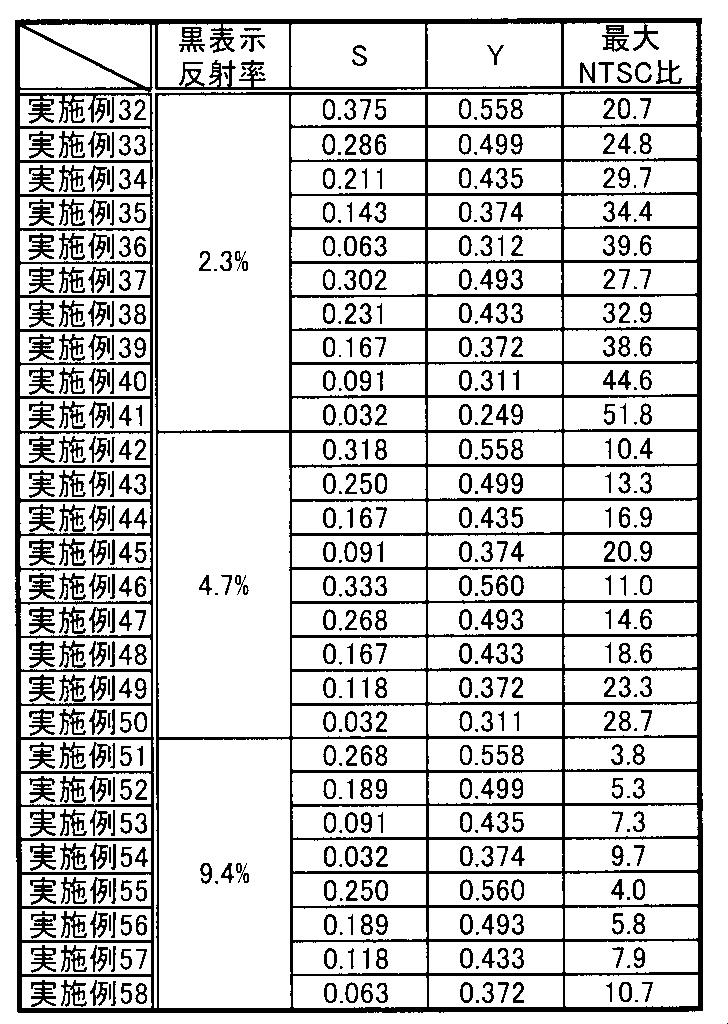
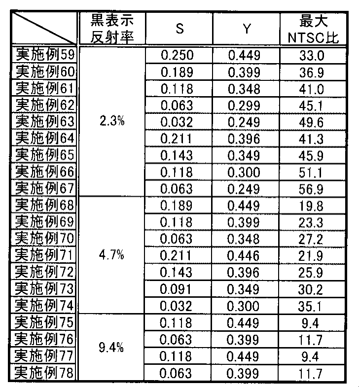
また、図4のグラフから、電子ペーパーのNTSC比が最大値を示すS値およびY値は、S+0.180<Y<S+0.360で示される関係式を満たすことが分かった。なお、上述した関係式の下限を示す式Y=S+0.180は、3つの(S,Y)の座標、(0.375,0.557)、(0.211,0.396)、(0.063,0.249)を用いて近似曲線を求めることにより得られた式である。また、上述した関係式の上限を示す直線Y=S+0.360は、3つの(S,Y)の座標、(0.375,0.731)、(0.143,0.494)、(0.063,0.415)を用いて近似曲線を求めることにより得られた式である。
1 … 透明基板
2 … 画素部
21 … 着色層
21R … 赤色着色層
21G … 緑色着色層
21B … 青色着色層
22 … 白色領域
3 … 対向電極基板
31 … 対向基材
32 … 対向電極層
4 … 表示媒体層
5 … 透明電極層
30 … 反射型表示素子
100 … 反射型表示装置
2 … 画素部
21 … 着色層
21R … 赤色着色層
21G … 緑色着色層
21B … 青色着色層
22 … 白色領域
3 … 対向電極基板
31 … 対向基材
32 … 対向電極層
4 … 表示媒体層
5 … 透明電極層
30 … 反射型表示素子
100 … 反射型表示装置
Claims (4)
- 白表示および黒表示を行う反射型表示素子とともに反射型表示装置に用いられる反射型表示装置用カラーフィルタであって、
透明基板と、
前記透明基板上に形成された赤色着色層、緑色着色層、および青色着色層を有する着色層、並びに前記着色層が形成されている着色層形成領域外に設けられた白色領域を備える画素部と、を有し、
前記反射型表示素子の白表示反射率に対する前記反射型表示装置の白表示反射率の割合と、前記反射型表示装置用カラーフィルタの前記画素部の面積に対する前記白色領域の面積比とが、下記に示す関係式を満たすように設計されたものであることを特徴とする反射型表示装置用カラーフィルタ。
S+0.180<Y<S+0.360
(式中、Yは前記反射型表示素子の前記白表示反射率に対する前記反射型表示装置の前記白表示反射率の割合、Sは前記反射型表示装置用カラーフィルタの前記画素部の面積に対する前記白色領域の面積比である。) - 前記反射型表示素子の黒表示反射率が2.3%~9.4%の範囲内であることを特徴とする請求の範囲第1項に記載の反射型表示装置用カラーフィルタ。
- 請求の範囲第1項または請求の範囲第2項に記載の反射型表示装置用カラーフィルタ、および白表示および黒表示を行う反射型表示素子を有することを特徴とする反射型表示装置。
- 請求の範囲第1項または請求の範囲第2項に記載の反射型表示装置用カラーフィルタと、
対向基材および前記対向基材上に形成された対向電極層を有する対向電極基板と、
前記反射型表示装置用カラーフィルタおよび前記対向電極基板の間に配置された表示媒体層と、
前記表示媒体層の対向電極基板側とは反対側に配置された透明電極層と
を有することを特徴とする電子ペーパー。
Applications Claiming Priority (2)
| Application Number | Priority Date | Filing Date | Title |
|---|---|---|---|
| JP2010276865A JP5724348B2 (ja) | 2010-12-13 | 2010-12-13 | 反射型表示装置用カラーフィルタ |
| JP2010-276865 | 2010-12-13 |
Publications (1)
| Publication Number | Publication Date |
|---|---|
| WO2012081334A1 true WO2012081334A1 (ja) | 2012-06-21 |
Family
ID=46244447
Family Applications (1)
| Application Number | Title | Priority Date | Filing Date |
|---|---|---|---|
| PCT/JP2011/075615 Ceased WO2012081334A1 (ja) | 2010-12-13 | 2011-11-07 | 反射型表示装置用カラーフィルタ |
Country Status (3)
| Country | Link |
|---|---|
| JP (1) | JP5724348B2 (ja) |
| TW (1) | TW201232062A (ja) |
| WO (1) | WO2012081334A1 (ja) |
Cited By (1)
| Publication number | Priority date | Publication date | Assignee | Title |
|---|---|---|---|---|
| CN108803127A (zh) * | 2018-07-13 | 2018-11-13 | 京东方科技集团股份有限公司 | 电子纸和电子标签 |
Families Citing this family (3)
| Publication number | Priority date | Publication date | Assignee | Title |
|---|---|---|---|---|
| TWI490614B (zh) * | 2013-01-24 | 2015-07-01 | E Ink Holdings Inc | 電泳顯示裝置 |
| CN114624938B (zh) * | 2020-12-08 | 2024-09-24 | 川奇光电科技(扬州)有限公司 | 彩色滤光层阵列及具有彩色滤光层阵列的彩色电泳显示器 |
| CN113050336A (zh) * | 2021-03-18 | 2021-06-29 | Tcl华星光电技术有限公司 | 一种阵列基板及液晶显示面板 |
Citations (6)
| Publication number | Priority date | Publication date | Assignee | Title |
|---|---|---|---|---|
| JPH10288706A (ja) * | 1997-04-14 | 1998-10-27 | Toppan Printing Co Ltd | カラーフィルタ |
| JPH1124063A (ja) * | 1997-07-03 | 1999-01-29 | Seiko Instr Inc | 反射型液晶表示装置およびその製造方法 |
| JP2000199897A (ja) * | 1999-01-05 | 2000-07-18 | Dainippon Printing Co Ltd | 反射型液晶表示装置 |
| WO2004077140A1 (ja) * | 2003-02-25 | 2004-09-10 | Bridgestone Corporation | 画像表示用パネル及び画像表示装置 |
| JP2004279572A (ja) * | 2003-03-13 | 2004-10-07 | Bridgestone Corp | カラーフィルター及びそれを用いた画像表示装置 |
| JP2005091442A (ja) * | 2003-09-12 | 2005-04-07 | Bridgestone Corp | 画像表示装置及びその製造方法 |
Family Cites Families (1)
| Publication number | Priority date | Publication date | Assignee | Title |
|---|---|---|---|---|
| JPWO2011155410A1 (ja) * | 2010-06-07 | 2013-08-01 | 新日鉄住金化学株式会社 | 電子ペーパー用カラー表示装置、及びその製造方法 |
-
2010
- 2010-12-13 JP JP2010276865A patent/JP5724348B2/ja not_active Expired - Fee Related
-
2011
- 2011-11-07 WO PCT/JP2011/075615 patent/WO2012081334A1/ja not_active Ceased
- 2011-11-28 TW TW100143515A patent/TW201232062A/zh unknown
Patent Citations (6)
| Publication number | Priority date | Publication date | Assignee | Title |
|---|---|---|---|---|
| JPH10288706A (ja) * | 1997-04-14 | 1998-10-27 | Toppan Printing Co Ltd | カラーフィルタ |
| JPH1124063A (ja) * | 1997-07-03 | 1999-01-29 | Seiko Instr Inc | 反射型液晶表示装置およびその製造方法 |
| JP2000199897A (ja) * | 1999-01-05 | 2000-07-18 | Dainippon Printing Co Ltd | 反射型液晶表示装置 |
| WO2004077140A1 (ja) * | 2003-02-25 | 2004-09-10 | Bridgestone Corporation | 画像表示用パネル及び画像表示装置 |
| JP2004279572A (ja) * | 2003-03-13 | 2004-10-07 | Bridgestone Corp | カラーフィルター及びそれを用いた画像表示装置 |
| JP2005091442A (ja) * | 2003-09-12 | 2005-04-07 | Bridgestone Corp | 画像表示装置及びその製造方法 |
Cited By (1)
| Publication number | Priority date | Publication date | Assignee | Title |
|---|---|---|---|---|
| CN108803127A (zh) * | 2018-07-13 | 2018-11-13 | 京东方科技集团股份有限公司 | 电子纸和电子标签 |
Also Published As
| Publication number | Publication date |
|---|---|
| JP2012128003A (ja) | 2012-07-05 |
| TW201232062A (en) | 2012-08-01 |
| JP5724348B2 (ja) | 2015-05-27 |
Similar Documents
| Publication | Publication Date | Title |
|---|---|---|
| US9442343B2 (en) | Electronic paper display device | |
| US8520168B2 (en) | Reflective color display device | |
| US20100172016A1 (en) | Electrophoretic display having high reflectance and contrast | |
| US7411721B2 (en) | Particle movement-type display device and particle movement-type display apparatus | |
| JP6008490B2 (ja) | ディスプレイ装置 | |
| JP5961975B2 (ja) | 電子ペーパー用カラーフィルタおよび電子ペーパー | |
| KR20110118477A (ko) | 컬러 필터 및 이를 채용한 디스플레이 장치 | |
| US8976162B2 (en) | Electrophoretic display device, driving method of the same, and electronic apparatus | |
| JP2004333864A (ja) | 電気泳動表示装置 | |
| CN102707431A (zh) | 一种显示装置 | |
| TW201243463A (en) | Reflective display panel | |
| JP5724348B2 (ja) | 反射型表示装置用カラーフィルタ | |
| JP2012181450A (ja) | 電気泳動表示装置およびその駆動方法、電子機器 | |
| JP5862164B2 (ja) | 電気泳動表示装置及び電気泳動表示装置の製造方法 | |
| CN102262327A (zh) | 图像显示系统 | |
| TWI227365B (en) | An electrophoretic display and a method of driving said display | |
| CN108681179A (zh) | 一种电子纸 | |
| JP2015114640A (ja) | 電気泳動表示装置及び電子機器 | |
| JP2007034037A (ja) | 粒子移動型表示装置 | |
| TWI424241B (zh) | 粒子顯示器之顯示三色之畫素驅動結構之顯色方法 | |
| JP3969067B2 (ja) | 反射型液晶表示装置用観察者側電極基板 | |
| KR101662229B1 (ko) | 반사투과형 디스플레이 장치 | |
| JP5253979B2 (ja) | 液晶マイクロカプセル積層体、液晶マイクロカプセル積層体基板及び表示装置 | |
| CN104460170A (zh) | 电泳显示装置及电子设备 | |
| KR20120017120A (ko) | 전기 영동 표시 장치 |
Legal Events
| Date | Code | Title | Description |
|---|---|---|---|
| 121 | Ep: the epo has been informed by wipo that ep was designated in this application |
Ref document number: 11849000 Country of ref document: EP Kind code of ref document: A1 |
|
| NENP | Non-entry into the national phase |
Ref country code: DE |
|
| 122 | Ep: pct application non-entry in european phase |
Ref document number: 11849000 Country of ref document: EP Kind code of ref document: A1 |