WO2012081162A1 - 動画像符号化装置、動画像復号装置、動画像符号化方法及び動画像復号方法 - Google Patents
動画像符号化装置、動画像復号装置、動画像符号化方法及び動画像復号方法 Download PDFInfo
- Publication number
- WO2012081162A1 WO2012081162A1 PCT/JP2011/006116 JP2011006116W WO2012081162A1 WO 2012081162 A1 WO2012081162 A1 WO 2012081162A1 JP 2011006116 W JP2011006116 W JP 2011006116W WO 2012081162 A1 WO2012081162 A1 WO 2012081162A1
- Authority
- WO
- WIPO (PCT)
- Prior art keywords
- coding
- partition
- block
- prediction
- intra
- Prior art date
Links
Images


Classifications
-
- H—ELECTRICITY
- H04—ELECTRIC COMMUNICATION TECHNIQUE
- H04N—PICTORIAL COMMUNICATION, e.g. TELEVISION
- H04N19/00—Methods or arrangements for coding, decoding, compressing or decompressing digital video signals
- H04N19/50—Methods or arrangements for coding, decoding, compressing or decompressing digital video signals using predictive coding
- H04N19/59—Methods or arrangements for coding, decoding, compressing or decompressing digital video signals using predictive coding involving spatial sub-sampling or interpolation, e.g. alteration of picture size or resolution
-
- H—ELECTRICITY
- H04—ELECTRIC COMMUNICATION TECHNIQUE
- H04N—PICTORIAL COMMUNICATION, e.g. TELEVISION
- H04N19/00—Methods or arrangements for coding, decoding, compressing or decompressing digital video signals
- H04N19/50—Methods or arrangements for coding, decoding, compressing or decompressing digital video signals using predictive coding
-
- H—ELECTRICITY
- H04—ELECTRIC COMMUNICATION TECHNIQUE
- H04N—PICTORIAL COMMUNICATION, e.g. TELEVISION
- H04N19/00—Methods or arrangements for coding, decoding, compressing or decompressing digital video signals
- H04N19/46—Embedding additional information in the video signal during the compression process
-
- G—PHYSICS
- G06—COMPUTING; CALCULATING OR COUNTING
- G06T—IMAGE DATA PROCESSING OR GENERATION, IN GENERAL
- G06T9/00—Image coding
-
- H—ELECTRICITY
- H04—ELECTRIC COMMUNICATION TECHNIQUE
- H04N—PICTORIAL COMMUNICATION, e.g. TELEVISION
- H04N19/00—Methods or arrangements for coding, decoding, compressing or decompressing digital video signals
- H04N19/10—Methods or arrangements for coding, decoding, compressing or decompressing digital video signals using adaptive coding
- H04N19/102—Methods or arrangements for coding, decoding, compressing or decompressing digital video signals using adaptive coding characterised by the element, parameter or selection affected or controlled by the adaptive coding
- H04N19/119—Adaptive subdivision aspects, e.g. subdivision of a picture into rectangular or non-rectangular coding blocks
-
- H—ELECTRICITY
- H04—ELECTRIC COMMUNICATION TECHNIQUE
- H04N—PICTORIAL COMMUNICATION, e.g. TELEVISION
- H04N19/00—Methods or arrangements for coding, decoding, compressing or decompressing digital video signals
- H04N19/10—Methods or arrangements for coding, decoding, compressing or decompressing digital video signals using adaptive coding
- H04N19/134—Methods or arrangements for coding, decoding, compressing or decompressing digital video signals using adaptive coding characterised by the element, parameter or criterion affecting or controlling the adaptive coding
- H04N19/157—Assigned coding mode, i.e. the coding mode being predefined or preselected to be further used for selection of another element or parameter
- H04N19/159—Prediction type, e.g. intra-frame, inter-frame or bidirectional frame prediction
-
- H—ELECTRICITY
- H04—ELECTRIC COMMUNICATION TECHNIQUE
- H04N—PICTORIAL COMMUNICATION, e.g. TELEVISION
- H04N19/00—Methods or arrangements for coding, decoding, compressing or decompressing digital video signals
- H04N19/10—Methods or arrangements for coding, decoding, compressing or decompressing digital video signals using adaptive coding
- H04N19/102—Methods or arrangements for coding, decoding, compressing or decompressing digital video signals using adaptive coding characterised by the element, parameter or selection affected or controlled by the adaptive coding
- H04N19/103—Selection of coding mode or of prediction mode
- H04N19/105—Selection of the reference unit for prediction within a chosen coding or prediction mode, e.g. adaptive choice of position and number of pixels used for prediction
-
- H—ELECTRICITY
- H04—ELECTRIC COMMUNICATION TECHNIQUE
- H04N—PICTORIAL COMMUNICATION, e.g. TELEVISION
- H04N19/00—Methods or arrangements for coding, decoding, compressing or decompressing digital video signals
- H04N19/50—Methods or arrangements for coding, decoding, compressing or decompressing digital video signals using predictive coding
- H04N19/593—Methods or arrangements for coding, decoding, compressing or decompressing digital video signals using predictive coding involving spatial prediction techniques
-
- H—ELECTRICITY
- H04—ELECTRIC COMMUNICATION TECHNIQUE
- H04N—PICTORIAL COMMUNICATION, e.g. TELEVISION
- H04N19/00—Methods or arrangements for coding, decoding, compressing or decompressing digital video signals
- H04N19/90—Methods or arrangements for coding, decoding, compressing or decompressing digital video signals using coding techniques not provided for in groups H04N19/10-H04N19/85, e.g. fractals
- H04N19/96—Tree coding, e.g. quad-tree coding
Definitions
- the present invention relates to a moving picture coding apparatus and a moving picture coding method for coding a moving picture with high efficiency, a moving picture decoding apparatus and a moving picture decoding method for decoding a moving picture coded with high efficiency, and It is about
- FIG. 14 is an explanatory drawing showing the intra prediction mode in the case where the block size of luminance is 4 ⁇ 4 pixels.
- nine intra prediction modes mode 0, mode 1,..., Mode 8 are defined.
- Mode 2 is average value prediction, which is a mode in which pixels in the current block are predicted with the average value of the adjacent pixels in the upper and left blocks.
- Modes outside mode 2 are directional predictions.
- mode 0 is vertical prediction, and the prediction image is generated by repeating the adjacent pixels of the upper block in the vertical direction. For example, in the case of vertical stripes, mode 0 is selected.
- Mode 1 is horizontal direction prediction, and generates a predicted image by repeating adjacent pixels of the left block in the horizontal direction.
- modes 3 to 8 generate interpolation pixels in a predetermined direction (direction indicated by an arrow in the drawing) using adjacent pixels of the upper or left block to generate a predicted image.
- the block size of luminance to which intra prediction is applied can be selected from 4 ⁇ 4 pixels, 8 ⁇ 8 pixels, 16 ⁇ 16 pixels, and in the case of 8 ⁇ 8 pixels, the block size is 4 ⁇ 4 pixels.
- nine intra prediction modes are defined.
- plane prediction is a mode in which pixels generated by obliquely interpolating adjacent pixels in the upper block and adjacent pixels in the left block are used as prediction values.
- the directional prediction mode in the case where the block size is 4 ⁇ 4 pixels or 8 ⁇ 8 pixels generates the predicted value in the direction (for example, 45 degrees) predetermined by the mode, so that the object boundary (edge) If the direction of) matches the direction indicated by the prediction mode, the prediction efficiency can be increased and the code amount can be reduced, but if the direction of the edge does not coincide with the direction indicated by the prediction mode, the prediction efficiency decreases Do. On the other hand, if the number of selectable directional prediction modes is increased, the probability that the direction of the edge coincides with the direction indicated by the prediction mode will increase, so it is assumed that the prediction efficiency will be high.
- MPEG-4 AVC ISO / IEC 14496-10
- the conventional moving picture coding apparatus is configured as described above, if the number of selectable directional prediction modes is increased, the probability that the direction of the edge matches the direction indicated by the prediction mode is increased, and the prediction efficiency is improved. It can be raised. However, even if the number of selectable directionality prediction modes is increased, the number of options for similar prediction images increases, so the extent to which the amount of computation can be increased due to the increase in the number of selectable directionality prediction modes There is a problem that the improvement of the coding efficiency is not seen and the contribution to the improvement of the coding efficiency is limited.
- the present invention has been made to solve the above-described problems, and is a moving picture coding apparatus capable of enhancing the degree of improvement in coding efficiency by increasing the mode number of directional prediction with a small amount of operation and code.
- the purpose is to obtain a moving picture coding method.
- Another object of the present invention is to provide a moving picture decoding apparatus and a moving picture decoding method capable of accurately decoding a moving picture from coded data whose coding efficiency is to be improved.
- the prediction image generation means is the intra prediction mode selected as the coding mode selected by the coding control means
- adjacent to the coding block divided by the block division means The prediction image is generated by performing an intra-frame prediction process using a certain pixel or a pixel adjacent to the coding block in the upper layer of the coding block.
- the variable length coding means causes the intra prediction direction of the coding block adjacent to the coding block divided by the block division means. And a flag indicating whether or not the intra prediction direction of the processing target coding block matches, and if it indicates that the directions match, any further adjacent coding block Also, information indicating whether the intra prediction direction matches the intra prediction direction is encoded.
- the prediction image generation means is the intra prediction mode selected by the coding control means, a pixel adjacent to the coding block divided by the block division means, or Since the prediction image is generated by performing intra-frame prediction processing using pixels adjacent to the coding block in the upper layer of the coding block, directional prediction can be performed with a small amount of operation and code. There is an effect that the improvement degree of the coding efficiency by the increase of the mode number can be enhanced.
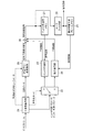
- FIG. 1 is a block diagram showing a moving picture coding apparatus according to a first embodiment of the present invention.
- the coding control unit 1 determines the maximum size of a coding block which is a processing unit when intra prediction processing (intra-frame prediction processing) or motion compensation prediction processing (inter-frame prediction processing) is performed.
- a process is performed to determine the upper limit hierarchy number when the coding block of the largest size is divided hierarchically.
- the coding control unit 1 may be configured to divide each of the coding blocks that are hierarchically divided among the available one or more coding modes (one or more intra coding modes, one or more inter coding modes). Implement a process to select a suitable coding mode. Further, the encoding control unit 1 determines, for each encoding block, the quantization parameter and transform block size used when the difference image is compressed, and also performs intra prediction used when prediction processing is performed. Implement a process to determine parameters or inter prediction parameters. The quantization parameter and the transform block size are included in the prediction differential coding parameter, and are output to the transform / quantization unit 7, the inverse quantization / inverse transform unit 8, the variable length coding unit 13, and the like. The coding control unit 1 constitutes coding control means.
- the block division unit 2 divides the input image into coding blocks of the maximum size determined by the coding control unit 1 and determines by the coding control unit 1
- the encoded block is hierarchically divided up to the upper limit hierarchy number.
- the block division unit 2 constitutes block division means. If the coding mode selected by the coding control unit 1 is the intra coding mode, the changeover switch 3 outputs the coding block divided by the block division unit 2 to the intra prediction unit 4 and the coding control unit 1 If the coding mode selected by the above is the inter coding mode, a process of outputting the coding block divided by the block division unit 2 to the motion compensation prediction unit 5 is performed.
- the intra prediction unit 4 When the intra prediction unit 4 receives the encoded block divided by the block division unit 2 from the changeover switch 3, the intra prediction unit 4 is adjacent to the encoded block stored by the intra prediction memory 10 with respect to the encoded block. Intra-frame prediction based on intra-prediction parameters output from the encoding control unit 1 using encoded pixels or encoded pixels adjacent to the encoded block in the upper layer of the encoded block The processing is performed to generate a predicted image.
- the motion compensation prediction unit 5 is stored by the motion compensation prediction frame memory 12 when the inter coding mode is selected by the coding control unit 1 as a coding mode corresponding to the coding block divided by the block division unit 2.
- the switch 3, the intra prediction unit 4 and the motion compensation prediction unit 5 constitute a prediction image generation means.
- the transform / quantization unit 7 transforms the differential image generated by the subtractor 6 (for example, DCT (discrete (discrete) (discrete)) in units of transform block size included in the prediction differential encoding parameter output from the encoding control unit 1.
- the transform / quantization unit 7 constitutes an image compression means.
- the inverse quantization / inverse transform unit 8 inverse quantizes the compressed data output from the transform / quantization unit 7 using the quantization parameter included in the predictive difference encoding parameter output from the encoding control unit 1.
- inverse transform processing eg, inverse DCT (inverse discrete cosine transform), inverse KL transform, etc.
- inverse quantization compressed data in units of transform block size included in the prediction differential encoding parameter Is carried out to output compressed data after inverse transformation as a local decoded prediction difference signal.
- the addition unit 9 adds a local decoded prediction difference signal output from the inverse quantization / inverse conversion unit 8 to a prediction signal indicating a predicted image generated by the intra prediction unit 4 or the motion compensation prediction unit 5 to perform local decoding. A process of generating a locally decoded image signal indicating an image is performed.
- the intra prediction memory 10 is a recording medium such as a RAM that stores a locally decoded image indicated by a locally decoded image signal generated by the addition unit 9 as an image used by the intra prediction unit 4 in the next intra prediction process.
- the loop filter unit 11 compensates for the coding distortion included in the local decoded image signal generated by the adding unit 9, and performs motion compensation prediction using the locally decoded image indicated by the locally decoded image signal after the coding distortion compensation as a reference image A process of outputting to the frame memory 12 is performed.
- the motion compensation prediction frame memory 12 is a recording medium such as a RAM that stores a locally decoded image after filtering processing by the loop filter unit 11 as a reference image used by the motion compensation prediction unit 5 in the next motion compensation prediction process.
- the variable-length coding unit 13 receives the compressed data output from the transform / quantization unit 7, the coding mode and the prediction differential coding parameter output from the coding control unit 1, and the intra output from the intra prediction unit 4. Variable length coding is performed on the prediction parameter or the inter prediction parameter output from the motion compensation prediction unit 5, and the compressed data, coding mode, prediction differential coding parameter, coded data of intra prediction parameter / inter prediction parameter are multiplexed. Perform processing to generate a bitstream that has been The variable-length coding unit 13 constructs a variable-length coding unit.
- FIG. 1 a coding control unit 1, a block division unit 2, a changeover switch 3, an intra prediction unit 4, a motion compensation prediction unit 5, a subtraction unit 6, and a transform / quantization unit 7 which are components of a moving picture coding apparatus.
- Hardware for each of the inverse quantization / inverse conversion unit 8, the addition unit 9, the loop filter unit 11 and the variable length coding unit 13 for example, a semiconductor integrated circuit on which a CPU is mounted, or a one-chip microcomputer Etc.
- FIG. 2 is a flow chart
- FIG. 10 is a block diagram showing a moving picture decoding apparatus in accordance with Embodiment 1 of the present invention.
- the variable-length decoding unit 21 is a code hierarchically divided from the coding blocks of the maximum size and the maximum size of a coding block which is a processing unit when intra prediction processing or motion compensation prediction processing is performed.
- the encoded data relating to the largest-sized encoded block and the hierarchically divided encoded block are identified.
- the variable length decoding unit 21 constructs a variable length decoding means.
- the changeover switch 22 When the coding mode according to the coding block output from the variable length decoding unit 21 is the intra coding mode, the changeover switch 22 outputs the intra prediction parameter output from the variable length decoding unit 21 to the intra prediction unit 23 When the coding mode is the inter coding mode, a process of outputting the inter prediction parameter output from the variable length decoding unit 21 to the motion compensation unit 24 is performed.
- the intra prediction unit 23 is a decoded pixel adjacent to the coding block stored in the intra prediction memory 27 or a decoded pixel adjacent to the coding block in the upper layer of the coding block. Based on the intra prediction parameter output from the changeover switch 22, the process of generating the predicted image by performing the intra-frame prediction process on the encoded block is performed using The motion compensation unit 24 performs motion compensation prediction processing on the coding block based on the inter prediction parameter output from the changeover switch 22 using the reference image of one or more frames stored in the motion compensation prediction frame memory 29. A process of generating a predicted image is performed by doing this.
- the changeover switch 22, the intra prediction unit 23, and the motion compensation unit 24 constitute a prediction image generation means.
- the inverse quantization / inverse transform unit 25 uses the quantization parameter included in the prediction differential encoding parameter output from the variable length decoding unit 21 to compress the encoding block output from the variable length decoding unit 21.
- Data is inversely quantized, and inverse transformation processing (eg, inverse DCT (inverse discrete cosine transformation), inverse KL transformation, etc.) of compression data of inverse quantization in units of transform block size included in the prediction differential encoding parameter
- inverse transformation processing eg, inverse DCT (inverse discrete cosine transformation), inverse KL transformation, etc.
- the inverse quantization / inverse transform unit 26 constitutes a difference image generation unit.
- the addition unit 26 adds the decoded prediction difference signal output from the inverse quantization / inverse conversion unit 25 and a prediction signal indicating a prediction image generated by the intra prediction unit 23 or the motion compensation unit 24 to indicate a decoded image. A process of generating a decoded image signal is performed.
- the addition unit 26 constitutes a decoded image generation unit.
- the intra prediction memory 27 is a recording medium such as a RAM that stores a decoded image indicated by the decoded image signal generated by the addition unit 26 as an image used by the intra prediction unit 23 in the next intra prediction process.
- the loop filter unit 28 compensates for the coding distortion included in the decoded image signal generated by the adding unit 26, and uses the decoded image indicated by the decoded image signal after the coding distortion compensation as a reference image. And output the decoded image to the outside as a reproduced image.
- the motion compensation prediction frame memory 29 is a recording medium such as a RAM that stores a decoded image after filtering processing by the loop filter unit 28 as a reference image used by the motion compensation unit 24 in the next motion compensation prediction process.
- FIG. 10 a variable-length decoding unit 21, a changeover switch 22, an intra prediction unit 23, a motion compensation unit 24, an inverse quantization / inverse conversion unit 25, an addition unit 26, and a loop filter unit 28 which are components of the moving picture decoding apparatus.
- the processing contents of the variable length decoding unit 21, the changeover switch 22, the intra prediction unit 23, the motion compensation unit 24, the inverse quantization / inverse conversion unit 25, the addition unit 26, and the loop filter unit 28 are described. All or a part is stored in the memory of the computer, and the CPU of the computer executes the program stored in the memory. Good.
- FIG. 11 is a flow chart showing processing contents of the moving picture decoding apparatus in accordance with Embodiment 1 of the present invention.
- the moving picture coding apparatus divides the video signal into regions of various sizes according to local changes in the space and time directions of the video signal, and performs intra-frame / inter-frame adaptive coding. It is characterized by doing.
- the video signal has a characteristic that the complexity of the signal changes locally in space and time, and when viewed spatially, it is compared on a specific video frame, for example, as in the sky or a wall.
- Some patterns have uniform signal characteristics in a wide image area, and some figures having a complex texture pattern in a small image area may be mixed in a person or a picture including fine texture.
- the encoding process generates a prediction difference signal with small signal power and entropy by temporal and spatial prediction, and performs a process to reduce the overall code amount, but the image with the largest possible prediction parameter used for the prediction process If it can be uniformly applied to the signal area, the code amount of the prediction parameter can be reduced.
- the same prediction parameter is applied to a large image area with respect to an image signal pattern having a large change in time and space, the number of prediction errors increases, so the code amount of the prediction difference signal can not be reduced. .
- the moving picture coding apparatus divides the area of the video signal hierarchically from a predetermined maximum block size. In addition, a configuration is adopted in which prediction processing and coding processing of prediction differences are adapted to each divided area.
- the video signal to be processed by the moving picture coding apparatus is a color of an arbitrary color space such as a YUV signal consisting of a luminance signal and two color difference signals, and an RGB signal output from a digital imaging device.
- a YUV signal consisting of a luminance signal and two color difference signals
- an RGB signal output from a digital imaging device In addition to the video signal, it is an arbitrary video signal such as a monochrome image signal or an infrared image signal, in which a video frame is composed of horizontal and vertical two-dimensional digital sample (pixel) rows.
- the tone of each pixel may be 8 bits, or may be a tone such as 10 bits or 12 bits.
- the input video signal is a YUV signal, unless otherwise specified.
- a processing data unit corresponding to each frame of video is referred to as a "picture", and in the first embodiment, the "picture” will be described as a signal of a video frame which is sequentially scanned (progressive scan). However, when the video signal is an interlaced signal, the "picture" may be a field image signal which is a unit constituting a video frame.
- the coding control unit 1 determines the maximum size of a coding block as a processing unit when intra prediction processing (intra-frame prediction processing) or motion compensation prediction processing (inter-frame prediction processing) is performed, and The upper limit hierarchy number is determined when the coding block of the largest size is divided hierarchically (step ST1 in FIG. 2).
- a method of determining the maximum size of the coding block for example, a method of determining the size according to the resolution of the input image for all pictures can be considered.
- a method of quantifying differences in local motion complexity of the input image as parameters determining the maximum size as a small value for a picture with large motion, and determining the maximum size as a large value for a picture with little movement.
- the upper limit hierarchy number for example, as the movement of the input image is intense, the hierarchy number is set deeper so that finer movement can be detected, and when the movement of the input image is small, the hierarchy number is set to be suppressed. There is a way to do it.
- the coding control unit 1 is configured to hierarchically divide each coding block out of the available one or more coding modes (M types of intra coding modes, N types of inter coding modes).
- the encoding mode corresponding to is selected (step ST2).
- the M types of intra coding modes prepared in advance will be described later.
- each coding block hierarchically divided by the block division unit 2 described later is further divided into partition units, it is possible to select the coding mode corresponding to each partition.
- each coding block is further divided into partitions.
- the method of selecting the coding mode by the coding control unit 1 is a known technique, and therefore detailed description will be omitted.
- the coding process for the coding block is performed using any available coding mode. There is a method of implementing to verify the coding efficiency, and selecting a coding mode with the highest coding efficiency among a plurality of available coding modes.
- the encoding control unit 1 determines, for each partition included in each encoding block, the quantization parameter and transform block size used when the differential image is compressed, and performs prediction processing. Intra prediction parameter or inter prediction parameter to be used in The coding control unit 1 outputs the prediction differential coding parameter including the quantization parameter and the conversion block size to the conversion / quantization unit 7, the inverse quantization / inverse conversion unit 8 and the variable length coding unit 13. Also, the prediction differential coding parameter is output to the intra prediction unit 4 as needed.
- the block division unit 2 When the block division unit 2 receives the video signal indicating the input image, the block division unit 2 divides the input image into coding blocks of the maximum size determined by the coding control unit 1, and the upper limit determined by the coding control unit 1.
- the encoded block is hierarchically divided up to the number of layers of H. Further, the encoded block is divided into partitions (step ST3).
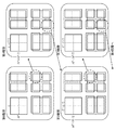
- FIG. 3 is an explanatory view showing how a coding block of maximum size is hierarchically divided into a plurality of coding blocks.
- the coding block of the largest size is the coding block B 0 of the zeroth layer, and has the size of (L 0 , M 0 ) in the luminance component.
- a coding block B n is obtained by hierarchically dividing to a predetermined depth separately defined in a quadtree structure starting from the coding block B 0 of the maximum size. There is.
- the coding block B n is an image area of size (L n , M n ).
- the size of the encoded block B n is defined as the size of the luminance component of the encoded block B n (L n, M n ).
- the encoding mode m (B n ) may be configured to use an individual mode for each color component, but thereafter, unless otherwise specified, YUV It will be described as referring to the coding mode for the luminance component of the signal, a 4: 2: 0 format coded block.
- the coding mode m (B n ) includes one or more intra coding modes (generally "INTRA") and one or more inter coding modes (generally "INTER"), As described above, the coding control unit 1 selects the coding mode with the highest coding efficiency for the coding block B n among all the coding modes available for the picture or the subset thereof. .
- the coding block B n is further divided into one or more prediction processing units (partitions), as shown in FIG.
- the partition belonging to the coding block B n P i n: is denoted as (i partition number in the n layer).
- Figure 8 is an explanatory view showing a partition P i n that belong to the coding block B n.
- the partitioning P i n that belong to the coding block B n is how made is included as information in the coding mode m (B n).
- Partition P i n is the prediction processing is carried out all in accordance with the coding mode m (B n), for each partition P i n, it is possible to select individual prediction parameters.
- the coding control unit 1 generates, for example, a block division state as shown in FIG. 4 with respect to the coding block of the maximum size, and specifies the coding block B n .
- the hatched portion in FIG. 4 (a) shows the distribution of partitions after division
- FIG. 4 (b) shows the situation where coding mode m (B n ) is assigned to partitions after hierarchical division in a quadtree graph It shows.
- nodes enclosed by ⁇ indicate nodes (coding block B n ) to which the coding mode m (B n ) is assigned.
- the encoding control unit 1 selects the intra coding mode (m (B n) ⁇ INTRA) , intra prediction partition P i n that belong to the divided coded block B n by the block division unit 2 output to section 4, the coding control unit 1 selects the inter coding mode (m (B n) ⁇ INTER) , and outputs the partition P i n that belong to the coding block B n to the motion compensation prediction unit 5 .
- the intra prediction unit 4 When the intra prediction unit 4 receives the partition P i n belonging to the coding block B n from the changeover switch 3 (step ST 4), although the specific processing content will be described later, the intra prediction determined by the coding control unit 1 based on the parameters, by performing the intra prediction process for each partition P i n, generates an intra prediction image (P i n) (step ST5).
- P i n denotes a partition
- (P i n) denote the predictive image partition P i n.
- Intra prediction parameters used to generate the intra-prediction image (P i n) is also the moving picture decoding apparatus, it is necessary to generate exactly the same intra prediction image (P i n), the variable length coding unit 13 It is multiplexed into a bitstream.
- the number of intra prediction directions that can be selected as the intra prediction parameter may be configured to be different depending on the size of the block to be processed. In a large size partition, the efficiency of intra prediction decreases, so the number of selectable intra prediction directions can be reduced, and the number of selectable intra prediction directions can be increased in small size partitions. For example, it may be configured in 34 directions in 4 ⁇ 4 pixel partitions and 8 ⁇ 8 pixel partitions, 17 directions in 16 ⁇ 16 pixel partitions, and 9 directions in 32 ⁇ 32 pixel partitions.
- the motion compensation prediction unit 5 receives the partition P i n belonging from the changeover switch 3 to the coding block B n (step ST4), based on the inter prediction parameters determined by the coding control unit 1, each partition P i by performing the inter prediction process for n, and generates an inter prediction image (P i n) (step ST6). That is, the motion compensation prediction unit 5 uses the reference image of one or more frames stored in the motion compensation prediction frame memory 12 to generate the coding block based on the inter prediction parameter output from the coding control unit 1. by carrying out the motion compensation prediction processing on, it generates an inter prediction image (P i n).
- Inter prediction parameters used to generate the inter prediction image (P i n) is also the moving picture decoding apparatus, it is necessary to generate exactly the same inter-prediction image (P i n), the variable length coding unit 13 It is multiplexed into a bitstream.
- Subtraction unit 6 receives the predictive picture (P i n) from the intra prediction unit 4 or the motion compensation prediction unit 5, the partition P i n that belong to coded blocks B n divided by the block division unit 2, the prediction by subtracting the image (P i n), to generate a prediction difference signal e i n indicating the difference image (step ST7).
- the subtraction unit 6 generates a prediction difference signal e i n, the transformation block size contained in the predictive differential coding parameter output from the coding controller 1, the prediction difference conversion processing for the signal e i n (e.g., DCT (discrete cosine transform) or the orthogonal transform for KL conversion and the base design have been made in advance to the particular learning sequence) with carrying out, the prediction difference coding using the quantization parameter contained in the parameter, the transform coefficients of the prediction difference signal e i n by quantization, inverse quantization and inverse transform to compressed data of the differential image is a transform coefficient after quantization It is output to unit 8 and variable length coding unit 13 (step ST8).
- DCT discrete cosine transform
- KL conversion and the base design have been made in advance to the particular learning sequence
- the inverse quantization / inverse transform unit 8 uses the quantization parameter included in the prediction differential coding parameter output from the coding control unit 1 to receive the compressed data.
- Inverse quantization processing of compression data of inverse quantization for example, inverse DCT (inverse discrete cosine transformation), inverse KL transformation, etc.
- the compressed data after the inverse conversion processing is output as a local decoded prediction difference signal to the addition unit 9 (step ST9).
- the addition unit 9 receives the locally decoded prediction difference signal from the inverse quantization / inverse conversion unit 8, the addition unit 9 receives the locally decoded prediction difference signal and the predicted image (P i generated by the intra prediction unit 4 or the motion compensation prediction unit 5 ).
- n generating a locally decoded image signal indicating a locally decoded partition image or a locally decoded coded block image (hereinafter referred to as “locally decoded image”) as a collection thereof by adding the prediction signal indicating n )
- the local decoded image signal is output to the loop filter unit 11 (step ST10).
- the intra-prediction memory 10 stores the locally decoded image for use in intra-prediction.
- the loop filter unit 11 When the loop filter unit 11 receives the locally decoded image signal from the adding unit 9, the loop filter unit 11 compensates for the coding distortion included in the locally decoded image signal, and the locally decoded image indicated by the locally decoded image signal after the coding distortion compensation Are stored in the motion compensation prediction frame memory 12 as a reference image (step ST11).
- the filtering process by the loop filter unit 11 may be performed in units of the largest encoded block of the locally decoded image signal to be input or in units of individual encoded blocks, or a locally decoded image signal corresponding to a macroblock for one screen May be performed collectively for one screen after the is input.
- steps ST4 ⁇ ST10 is repeatedly performed until the processing for the partitions P i n that belong to all the coding blocks B n divided by the block dividing unit 2 is completed (step ST12).
- the variable-length coding unit 13 outputs the compressed data output from the transform / quantization unit 7, the encoding mode and the prediction difference encoding parameter output from the encoding control unit 1, and the intra prediction unit 4.
- Variable length coding is performed on the intra prediction parameter or the inter prediction parameter output from the motion compensation prediction unit 5, and the compressed data, coding mode, prediction differential coding parameter, and coded data of intra prediction parameter / inter prediction parameter are used.
- a multiplexed bit stream is generated (step ST13).
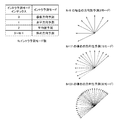
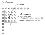
- FIG. 5 is an explanatory diagram showing an example of each partition P i n selectable in intra prediction parameters belonging to the coding block B n (intra prediction mode).
- FIG. 5 shows prediction direction vectors corresponding to the intra prediction mode, and is designed so that the relative angle between prediction direction vectors decreases as the number of selectable intra prediction modes increases.
- the intra prediction unit 4 based on the intra prediction parameters (intra prediction mode) for the luminance signal partitions P i n, described intra process of generating an intra prediction signal of the luminance signal.
- k is a positive scalar value
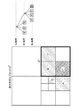
- the integer pixel When the reference pixel is at an integer pixel position, the integer pixel is set as the prediction value of the prediction target pixel. When the reference pixel is not at an integer pixel position, an interpolated pixel generated from an integer pixel adjacent to the reference pixel is set as a predicted value. In the example of FIG. 6, since the reference pixel is not at the integer pixel position, the average value of two pixels adjacent to the reference pixel is used as the predicted value. Note that interpolation pixels may be generated not only from adjacent two pixels but also from adjacent two or more pixels as prediction values.
- Intra prediction unit 4 a similar procedure to generate a predicted pixel for all the pixels of the luminance signal in the partition P i n, and outputs an intra prediction image thus generated (P i n).
- Intra prediction parameters are used for generating the intra prediction image (P i n), as described above, is output to the variable length coding unit 13 for multiplexing the bitstream.
- Intra-prediction image (P i n) is the luminance signal in a partition P i n, but are generated as described above, as shown in FIG. 7, the partition P j n-1 (j: partition P i n the For the luminance signal in the partition number of the upper partition in the n ⁇ 1 layer, an intra-prediction image (P j n ⁇ 1 ) is generated in the same manner.
- Intra prediction is a means to predict an unknown region in a screen from a known region, but the image signal has a large local change in the spatial direction, so by selecting from among predicted images of different properties Prediction efficiency can be improved. Therefore, when the number of directions of the intra prediction mode is increased by configuring as described above, the mutual similarity of the generated predicted images is reduced as compared to the case where the intra prediction mode is increased, and the prediction images rich in variation Since it is possible to select from among them, it is possible to increase the degree of coding efficiency improvement by increasing the number of intra prediction modes.
- the predicted image of the lower partition can be generated by cutting out a part of the predicted image of the upper partition, compared to the case where the prediction mode is increased by increasing the prediction direction, There is also an effect that the amount of computation can be reduced.
- variable length coding unit 13 outputs the result.
- variable-length coding unit 13 performs variable-length coding on the intra prediction parameter output from the intra prediction unit 4 and multiplexes the codeword of the intra prediction parameter into a bit stream.
- select a representative prediction direction vector (prediction direction representative vector) from among the prediction direction vectors of a plurality of directional predictions, and select the intra prediction parameter as the index of the prediction direction representative vector (prediction direction representative vector).
- the code amount can be expressed by performing the Huffman coding such as arithmetic coding according to the probability model for each index by representing the difference between the index) and the prediction direction representative vector (prediction direction difference index). It may be configured to reduce and encode.
- variable-length decoding unit 21 receives a bit stream generated by the moving picture coding apparatus of FIG. 1, the variable-length decoding section 21 performs variable-length decoding processing on the bit stream (step ST21 of FIG. 11).
- the frame size is decoded in units of sequence or picture composed of.
- variable-length decoding unit 21 decodes the frame size, the maximum coding block size determined by the moving picture coding apparatus of FIG.
- a code serving as a processing unit when intra prediction processing or motion compensation prediction processing is performed Determine the maximum size of the coding block and the upper limit of the number of division layers (the number of layers of coding blocks hierarchically divided from the coding block of maximum size) according to the same procedure as the moving picture coding device (steps ST22).
- the maximum size of the coding block is determined to be the size according to the resolution of the input image for all the pictures, the moving image of FIG.
- the maximum size of the coding block is determined in the same manner as in the image coding apparatus.
- variable-length decoding unit 21 After determining the maximum size of the coding block and the number of layers of the coding block, the variable-length decoding unit 21 uses the largest coding block as a starting point to grasp the hierarchical division state of each coding block, Among the encoded data multiplexed in the bit stream, the encoded data related to each encoded block is specified, and the encoding mode assigned to each encoded block is decoded from the encoded data.
- the variable length decoding unit 21 refers to the division information of the partition P i n that belong to coded blocks B n, which is included in the coding mode, in the coded data multiplexed in the bit stream in, it identifies the coded data according to each partition P i n (step ST23).
- Variable-length decoder 21 the compressed data from the encoded data according to each partition P i n, predictive differential coding parameters, intra prediction parameters / inter prediction parameters by variable length decoding, the compressed data and predictive differential coding parameters Is output to the dequantization / inverse transform unit 25 and the coding mode and the intra prediction parameter / inter prediction parameter are output to the changeover switch 22 (step ST24).
- the prediction direction representative index and the prediction direction difference index are multiplexed in the bitstream, the prediction direction representative index and the prediction direction difference index are entropy decoded by arithmetic decoding or the like according to each probability model,
- the intra prediction parameter is specified from the prediction direction representative index and the prediction direction difference index.
- Changeover switch 22 when the coding mode of the partition P i n that belong to coded blocks B n output from the variable length decoding unit 21 is an intra coding mode, the intra prediction parameter output from the variable length decoding unit 21 Is output to the intra prediction unit 23. If the coding mode is the inter coding mode, the inter prediction parameter output from the variable length decoding unit 21 is output to the motion compensation unit 24.
- the intra prediction unit 23 as well as receiving the intra prediction parameters from the changeover switch 22 (step ST25), an intra prediction unit 4 in FIG. 1, on the basis of the intra prediction parameter, an intra prediction process for each partition P i n by performing, for generating an intra prediction image (P i n) (step ST26). That is, the intra prediction unit 23, the pixel of the decoded adjacent to the partition P i n that is stored by the intra prediction memory 27, or the partition P j n-1 of the upper layer of the partition P i n using decoded pixels that are adjacent, and generates a predicted image (P i n) by performing intra-frame prediction processing on partitioned P i n based on the intra prediction parameters.
- Motion compensation unit 24 receives the inter prediction parameters from the changeover switch 22 (step ST25), like the motion compensation prediction unit 5 of FIG. 1, on the basis of the inter prediction parameters, inter-prediction processing for each partition P i n by implementing, it generates an inter prediction image (P i n) (step ST27). That is, motion compensation unit 24 uses one or more frames of reference images stored by the motion compensated prediction frame memory 29, by performing the motion compensation prediction processing on partition P i n based on the inter prediction parameters, It generates an inter prediction image (P i n).
- the inverse quantization / inverse transform unit 25 When the inverse quantization / inverse transform unit 25 receives the predictive difference coding parameter from the variable length decoding unit 21, the inverse quantization / inverse transform unit 25 outputs the variable from the variable length decoding unit 21 using the quantization parameter included in the predictive difference coding parameter.
- the compressed data relating to the encoded block is inversely quantized, and inverse transformation processing of the compressed data of inverse quantization (for example, inverse DCT (inverse discrete cosine) is performed in units of transform block size included in the prediction differential encoding parameter Conversion) and inverse transformation such as inverse KL transformation) to output the compressed data after the inverse transformation to the addition unit 26 as a decoded prediction difference signal (a signal indicating a difference image before compression) (step ST28).
- inverse DCT inverse discrete cosine
- Addition unit 26 adds the decoded prediction difference signal outputted from the inverse quantization and inverse transform unit 25, and a prediction signal indicating a predicted image generated by the intra prediction unit 23 or the motion compensation unit 24 (P i n) By doing this, a decoded image signal indicating a decoded partition image or a decoded image as a collection thereof is generated, and the decoded image signal is output to the loop filter unit 28 (step ST29). Further, the decoded image is stored in the intra prediction memory 27 for use in intra prediction.
- loop filter unit 28 compensates for the coding distortion included in the decoded image signal, and uses the decoded image indicated by the decoded image signal after the coding distortion compensation as a reference image.
- the motion compensation prediction frame memory 29 is stored, and the decoded image is output as a reproduced image (step ST30).
- the filtering process by the loop filter unit 28 may be performed in units of the largest encoded block of the input decoded image signal or in individual encoded blocks, or a decoded image signal corresponding to one screen worth of macroblocks is input. After being done, it may be done collectively for one screen. Processing in steps ST23 ⁇ ST29 are repeated until the processing for the partitions P i n that belong to all the coding blocks B n is completed (step ST31).
- the intra prediction unit 4 of the moving picture coding device performs block division. pixel is adjacent to the divided partition P i n by Part 2, or to carry out the intra-frame prediction process using pixels adjacent to the partition P j n-1 of the upper layer of the partition P i n in so constituted as to generate a predicted image (P i n), an effect that can increase the degree of improvement in coding efficiency with a small amount of calculation.
- the intra prediction memory 27 decoded pixels adjacent to the partition P i n that are stored, or intra-frame prediction process using the partition P i n the upper layer of the partition P j n-1 decoded pixels adjacent to the since it is configured to generate a predicted image (P i n) by carrying out an effect capable of correctly decoding the moving picture from the encoded data improved coding efficiency is achieved.
- variable length coding unit 13 of the moving picture coding apparatus performs variable length coding of the intra prediction parameter in the partition to be coded in the first embodiment
- the intra prediction in the partition to be coded is described.
- Variable length coding is performed on an intra merge flag indicating whether the parameter is the same as the intra prediction parameter in the partition adjacent to the partition, and the adjacent is the same if the intra prediction parameter is the same
- the intra-merge direction specifying the partition may be variable-length encoded, and if the intra-prediction parameters are not the same, the intra-prediction parameters in the partition to be encoded may be variable-length encoded.
- variable length decoding unit 21 of the moving picture decoding apparatus has shown variable length decoding of the intra prediction parameter in the partition from the encoded data of the partition to be decoded.
- the encoded data relating to the target partition is subjected to variable length decoding of an intra merge flag indicating whether or not the intra prediction parameter in the relevant partition and the adjacent partition is the same, and the intra merge flag corresponds to that in the relevant partition and the adjacent partition If it indicates that the intra-prediction parameters are the same, variable length decoding is performed on an intra-merge direction specifying an adjacent partition from the encoded data, and the intra-merge flag is set in the corresponding partition and the adjacent partition.
- intra prediction parameter indicating not the same may be the intra prediction parameters in the partition from the encoded data as variable-length decoding.
- the parts other than the coding and decoding of the intra prediction parameter are the same as those in the above-mentioned Embodiment 1, so in this Embodiment 2, the coding of the intra prediction parameter and Only the decryption will be described.
- the variable-length coding unit 13 of the moving picture coding apparatus changes the intra prediction parameters in the partition P i n to be coded (target to be processed) into a variable-length code.
- the intra prediction parameter variable length encoded intra-merge flag indicating whether same as either an intra prediction parameter of the partition adjacent the partition P i n.
- the variable length coding unit 13 indicates the intra partition indicating which intra partition is the same as the intra prediction parameter in the adjacent partitions.
- Variable-length encode merge direction On the other hand, the intra merge flag, indicating that not the same intra prediction parameters, as shown in FIG. 12 (B), variable length encoded intra prediction parameters in a partitioned P i n the coded (in this case, It becomes the same encoding as the above-mentioned Embodiment 1).
- the intra-merge direction is the same as the left partition or the upper partition. It becomes a flag indicating whether they are the same.
- FIG. 13 (B) a flag indicating the same among the three candidates with the left partition, the upper left partition, and the upper partition as candidates as adjacent partitions. It can also be configured as As a matter of course, when the intra prediction parameters of the target adjacent partitions are all the same, there is no need to encode the intra-merge direction. Therefore, in such a case, as shown in FIG. 12D, the intra-merge direction may not be encoded.
- the partition is scanned in a direction away from the upper left direction, and the first partition encoded in intra prediction mode is the adjacent partition on the upper side or the left side, respectively.
- the partition is scanned in a direction away from the upper left direction, and the first partition encoded in intra prediction mode is the adjacent partition on the upper side or the left side, respectively.
- the following configuration can be made. That, numN ⁇ For NUMC, from among the prediction direction vectors of a plurality of directional prediction of partition P i n to be coded representative corresponding one of the prediction direction vector selectable intra prediction direction in the adjacent partitions By doing this, it is determined whether or not the intra prediction parameters match. In this case, as shown in FIG. 12 (C), when it is determined that the intra prediction parameters match, one of the plurality of corresponding intra prediction directions is made the partition P to be encoded. Encode the intra prediction direction residual parameter indicating whether it is selected by i n .
- a representative prediction direction vector corresponds to one of selectable intra prediction directions in partition P i n to be encoded
- the intra prediction direction residual parameter Since the intra prediction mode is considered to have directionality dependent on the texture of the image to be encoded, it is likely that a locally similar prediction mode will appear. Therefore, the intra prediction parameter can be encoded with a smaller amount of information by encoding the intra prediction parameter using the intra merging flag and the inter merging direction.
- variable-length decoding unit 21 of the moving picture decoding apparatus when the variable-length decoding unit 21 of the moving picture decoding apparatus according to the second embodiment performs variable-length decoding of the intra prediction parameter in the partition P i n to be decoded (processing target), its intra prediction parameter, variable length decoding the intra merge flag indicating whether or not the same as the intra prediction parameters of the partition adjacent the partition P i n. Further, when the intra-merge flag indicates that the intra-merge flag is the same intra-prediction parameter, the variable-length decoding unit 21 performs intra-merge indicating which of the adjacent partitions the intra-prediction parameter is the same as. Variable-length decode the direction. On the other hand, the intra merge flag, indicating that not the same intra prediction parameters, as shown in FIG. 12 (B), variable-length decodes the intra prediction parameters in a partitioned P i n to be decoded (in this case, the above-described Decoding is the same as in mode 1 of
- the intra-merge direction is the same as the left partition or the upper partition. It becomes a flag indicating whether they are the same.
- FIG. 13B in the case where a left partition, an upper left partition, and an upper partition are listed as candidates as adjacent partitions, which one of the three candidates is the same as the candidate? It becomes a flag indicating.
- the intra prediction parameters of adjacent partitions to be processed are all the same, there is no need to decode the intra-merge direction. Therefore, in such a case, as shown in FIG. 12D, the intra-merge direction may not be decoded.
- the partition is scanned in a direction away from the upper left direction, and the first partition encoded in intra prediction mode is the adjacent partition on the upper side or the left side, respectively. You may do it.
- the selectable intra prediction direction number NumN and the selectable intra prediction direction number NumC in the partition to be decoded are not equal, the following configuration can be made. That is, in the case of numN ⁇ NUMC, from the prediction direction vectors of a plurality of directional prediction of partition P i n to be decoded, the representative prediction direction vector corresponding one of the selectable intra prediction direction in the adjacent partitions Thus, it is determined whether or not the intra prediction parameters match. In this case, as shown in FIG. 12C, when it is determined that the intra prediction parameters match, one of the plurality of corresponding intra prediction directions is made to be the partition P i to be decoded. Encode an intra prediction direction residual parameter indicating whether n is selected.
- a representative prediction direction vector is made to correspond to one of selectable intra prediction directions in the partition P i n to be decoded among prediction direction vectors of a plurality of directional predictions of adjacent partitions.
- the variable-length coding / decoding unit according to the second embodiment is not in the prediction mode in which the processing target partition or the adjacent partition is not a part of the intra-predicted image in the upper layer described in the first embodiment. Can also be applied.
- the present invention allows free combination of each embodiment, or modification of any component of each embodiment, or omission of any component in each embodiment. .
- the moving picture coding apparatus, the moving picture decoding apparatus, the moving picture coding method, and the moving picture decoding method according to the present invention have coding efficiency by increasing the mode number of directional prediction with a small amount of operation and code.
- Video encoding apparatus and encoding method for encoding moving pictures with high efficiency, and moving pictures for decoding moving pictures encoded with high efficiency It is suitable for use in a decoding device, a moving image decoding method, and the like.
Landscapes
- Engineering & Computer Science (AREA)
- Multimedia (AREA)
- Signal Processing (AREA)
- Physics & Mathematics (AREA)
- General Physics & Mathematics (AREA)
- Theoretical Computer Science (AREA)
- Compression Or Coding Systems Of Tv Signals (AREA)
Priority Applications (29)
| Application Number | Priority Date | Filing Date | Title |
|---|---|---|---|
| EP19152902.3A EP3493545B1 (en) | 2010-12-17 | 2011-11-01 | Moving image encoding device, moving image decoding device, moving image encoding method and moving image decoding method |
| BR112013014258-8A BR112013014258B1 (pt) | 2010-12-17 | 2011-11-01 | Dispositivo de codificação de imagem, e, método de codificação de imagem |
| MX2016003712A MX351072B (es) | 2010-12-17 | 2011-11-01 | Dispositivo de codificación de imagen, dispositivo de decodificación de imagen, método de codificación de imagen y método de decodificación de imagen. |
| US13/991,041 US10432956B2 (en) | 2010-12-17 | 2011-11-01 | Image coding device, image decoding device, image coding method, and image decoding method |
| JP2012548618A JP5711266B2 (ja) | 2010-12-17 | 2011-11-01 | 動画像符号化装置及び動画像符号化方法 |
| MX2013006878A MX337875B (es) | 2010-12-17 | 2011-11-01 | Dispositivo de codificacion de imagen, dispositivo de decodificacion de imagen, metodo de codificacion de imagen y metodo de decodificacion de imagen. |
| EP11848087.0A EP2654300B1 (en) | 2010-12-17 | 2011-11-01 | Moving image encoding device, moving image decoding device, moving image encoding method and moving image decoding method |
| KR1020137018737A KR101538248B1 (ko) | 2010-12-17 | 2011-11-01 | 화상 부호화 장치 |
| CA2820014A CA2820014C (en) | 2010-12-17 | 2011-11-01 | Image coding device, image decoding device, image coding method, and image decoding method |
| RU2013132933/08A RU2547617C2 (ru) | 2010-12-17 | 2011-11-01 | Устройство кодирования изображений, устройство декодирования изображений, способ кодирования изображений и способ декодирования изображений |
| ES11848087T ES2718426T3 (es) | 2010-12-17 | 2011-11-01 | Dispositivo de codificación de imágenes en movimiento, dispositivo de decodificación de imágenes en movimiento, método de codificación de imágenes en movimiento y método de decodificación de imágenes en movimiento |
| CN2011800605992A CN103262539A (zh) | 2010-12-17 | 2011-11-01 | 运动图像编码装置、运动图像解码装置、运动图像编码方法以及运动图像解码方法 |
| EP19152900.7A EP3493543B1 (en) | 2010-12-17 | 2011-11-01 | Moving image encoding device, moving image decoding device, moving image encoding method and moving image decoding method |
| EP19152901.5A EP3493544B1 (en) | 2010-12-17 | 2011-11-01 | Moving image encoding device, moving image decoding device, moving image encoding method and moving image decoding method |
| TW100141983A TWI519141B (zh) | 2010-12-17 | 2011-11-17 | 動畫像編碼裝置、動畫像解碼裝置、動畫像編碼方法及動畫像解碼方法 |
| TW109129541A TWI718084B (zh) | 2010-12-17 | 2011-11-17 | 畫像編碼裝置、動畫像解碼裝置及動畫像編碼資料 |
| TW109145509A TWI728944B (zh) | 2010-12-17 | 2011-11-17 | 動畫像編碼裝置、動畫像解碼裝置及記錄媒體 |
| TW107117976A TWI666925B (zh) | 2010-12-17 | 2011-11-17 | 動畫像編碼裝置、動畫像解碼裝置、動畫像編碼方法、動畫像解碼方法及記錄媒體 |
| TW108121752A TWI706671B (zh) | 2010-12-17 | 2011-11-17 | 動畫像編碼裝置、動畫像解碼裝置、動畫像編碼方法、動畫像解碼方法及記錄媒體動畫像編碼資料 |
| TW104141491A TWI566590B (zh) | 2010-12-17 | 2011-11-17 | 動畫像編碼裝置、動畫像解碼裝置、動畫像編碼方法、動畫像解碼方法及記錄媒體 |
| TW105138645A TWI647952B (zh) | 2010-12-17 | 2011-11-17 | 動畫像編碼裝置、動畫像解碼裝置、動畫像編碼方法、動畫像解碼方法及記錄媒體 |
| TW110114542A TWI740801B (zh) | 2010-12-17 | 2011-11-17 | 畫像編碼裝置、動畫像解碼裝置及記錄媒體 |
| US16/545,817 US10827193B2 (en) | 2010-12-17 | 2019-08-20 | Image coding device, image decoding device, image coding method, and image decoding method |
| US16/545,806 US10820001B2 (en) | 2010-12-17 | 2019-08-20 | Image coding device, image decoding device, image coding method, and image decoding method |
| US16/545,740 US10820000B2 (en) | 2010-12-17 | 2019-08-20 | Image coding device, image decoding device, image coding method, and image decoding method |
| US17/031,275 US11350120B2 (en) | 2010-12-17 | 2020-09-24 | Image coding device, image decoding device, image coding method, and image decoding method |
| US17/745,040 US11831892B2 (en) | 2010-12-17 | 2022-05-16 | Image coding device, image decoding device, image coding method, and image decoding method |
| US17/745,062 US11831893B2 (en) | 2010-12-17 | 2022-05-16 | Image coding device, image decoding device, image coding method, and image decoding method |
| US18/107,764 US11831896B2 (en) | 2010-12-17 | 2023-02-09 | Image coding device, image decoding device, image coding method, and image decoding method |
Applications Claiming Priority (2)
| Application Number | Priority Date | Filing Date | Title |
|---|---|---|---|
| JP2010281743 | 2010-12-17 | ||
| JP2010-281743 | 2010-12-17 |
Related Child Applications (4)
| Application Number | Title | Priority Date | Filing Date |
|---|---|---|---|
| US13/991,041 A-371-Of-International US10432956B2 (en) | 2010-12-17 | 2011-11-01 | Image coding device, image decoding device, image coding method, and image decoding method |
| US16/545,740 Division US10820000B2 (en) | 2010-12-17 | 2019-08-20 | Image coding device, image decoding device, image coding method, and image decoding method |
| US16/545,817 Division US10827193B2 (en) | 2010-12-17 | 2019-08-20 | Image coding device, image decoding device, image coding method, and image decoding method |
| US16/545,806 Division US10820001B2 (en) | 2010-12-17 | 2019-08-20 | Image coding device, image decoding device, image coding method, and image decoding method |
Publications (1)
| Publication Number | Publication Date |
|---|---|
| WO2012081162A1 true WO2012081162A1 (ja) | 2012-06-21 |
Family
ID=46244282
Family Applications (1)
| Application Number | Title | Priority Date | Filing Date |
|---|---|---|---|
| PCT/JP2011/006116 WO2012081162A1 (ja) | 2010-12-17 | 2011-11-01 | 動画像符号化装置、動画像復号装置、動画像符号化方法及び動画像復号方法 |
Country Status (14)
| Country | Link |
|---|---|
| US (8) | US10432956B2 (ru) |
| EP (4) | EP2654300B1 (ru) |
| JP (6) | JP5711266B2 (ru) |
| KR (1) | KR101538248B1 (ru) |
| CN (1) | CN103262539A (ru) |
| BR (1) | BR112013014258B1 (ru) |
| CA (5) | CA3052608C (ru) |
| ES (1) | ES2718426T3 (ru) |
| MX (2) | MX351072B (ru) |
| RU (5) | RU2602365C2 (ru) |
| SG (3) | SG10201509231QA (ru) |
| TR (1) | TR201904717T4 (ru) |
| TW (8) | TWI706671B (ru) |
| WO (1) | WO2012081162A1 (ru) |
Cited By (5)
| Publication number | Priority date | Publication date | Assignee | Title |
|---|---|---|---|---|
| JP2013258759A (ja) * | 2011-06-13 | 2013-12-26 | Panasonic Corp | 画像復号方法および画像復号装置 |
| RU2653270C2 (ru) * | 2013-12-10 | 2018-05-07 | Кэнон Кабусики Кайся | Улучшенный палитровый режим в hevc |
| JP2018121283A (ja) * | 2017-01-27 | 2018-08-02 | 日本放送協会 | 予測装置、符号化装置、復号装置、及びプログラム |
| US10834412B2 (en) | 2013-12-10 | 2020-11-10 | Canon Kabushiki Kaisha | Method and apparatus for encoding or decoding blocks of pixel |
| JPWO2020059616A1 (ja) * | 2018-09-21 | 2021-09-09 | 日本放送協会 | 画像符号化装置、画像復号装置、及びプログラム |
Families Citing this family (5)
| Publication number | Priority date | Publication date | Assignee | Title |
|---|---|---|---|---|
| US10432956B2 (en) | 2010-12-17 | 2019-10-01 | Mitsubishi Electric Corporation | Image coding device, image decoding device, image coding method, and image decoding method |
| US20180332312A1 (en) * | 2017-05-09 | 2018-11-15 | Futurewei Technologies, Inc. | Devices And Methods For Video Processing |
| CN108846874A (zh) * | 2018-06-27 | 2018-11-20 | 广州视源电子科技股份有限公司 | 信号发生器的图像生成方法和装置 |
| EP3860122B1 (en) * | 2018-09-28 | 2024-03-27 | JVCKenwood Corporation | Image decoding device, image decoding method, and image decoding program |
| CN111950587B (zh) * | 2020-07-02 | 2024-04-16 | 北京大学深圳研究生院 | 帧内编码块划分处理方法和硬件装置 |
Citations (3)
| Publication number | Priority date | Publication date | Assignee | Title |
|---|---|---|---|---|
| JP2008104228A (ja) * | 2005-01-04 | 2008-05-01 | Samsung Electronics Co Ltd | イントラblモードを考慮したビデオデコーディング方法、ビデオデコーダ、及び、記録媒体 |
| JP2010530184A (ja) * | 2007-06-15 | 2010-09-02 | クゥアルコム・インコーポレイテッド | ビデオブロック予測モードの適応形符号化 |
| WO2010116869A1 (ja) * | 2009-04-08 | 2010-10-14 | シャープ株式会社 | 動画像符号化装置および動画像復号装置 |
Family Cites Families (20)
| Publication number | Priority date | Publication date | Assignee | Title |
|---|---|---|---|---|
| JP3263807B2 (ja) | 1996-09-09 | 2002-03-11 | ソニー株式会社 | 画像符号化装置および画像符号化方法 |
| CA2566368A1 (en) * | 2004-05-17 | 2005-11-24 | Nokia Corporation | Audio encoding with different coding frame lengths |
| JP4359773B2 (ja) | 2004-06-22 | 2009-11-04 | ソニー株式会社 | 画像圧縮処理装置、画像圧縮処理方法および画像圧縮処理プログラム |
| KR100679035B1 (ko) | 2005-01-04 | 2007-02-06 | 삼성전자주식회사 | 인트라 bl 모드를 고려한 디블록 필터링 방법, 및 상기방법을 이용하는 다 계층 비디오 인코더/디코더 |
| US20080165849A1 (en) * | 2005-07-22 | 2008-07-10 | Mitsubishi Electric Corporation | Image encoder and image decoder, image encoding method and image decoding method, image encoding program and image decoding program, and computer readable recording medium recorded with image encoding program and computer readable recording medium recorded with image decoding program |
| US8189934B2 (en) | 2006-03-27 | 2012-05-29 | Panasonic Corporation | Image coding apparatus and image decoding apparatus |
| US8422803B2 (en) | 2007-06-28 | 2013-04-16 | Mitsubishi Electric Corporation | Image encoding device, image decoding device, image encoding method and image decoding method |
| CN103281542B (zh) * | 2007-06-29 | 2017-07-14 | 夏普株式会社 | 图像编码装置、图像编码方法、图像译码装置、图像译码方法 |
| JP4650461B2 (ja) * | 2007-07-13 | 2011-03-16 | ソニー株式会社 | 符号化装置、符号化方法、プログラム、及び記録媒体 |
| JP2009055542A (ja) * | 2007-08-29 | 2009-03-12 | Toshiba Corp | 動画像符号化装置および動画像符号化方法 |
| KR101566564B1 (ko) * | 2007-10-16 | 2015-11-05 | 톰슨 라이센싱 | 기하학적으로 분할된 수퍼 블록들의 비디오 인코딩 및 디코딩 방법 및 장치 |
| JP5137687B2 (ja) | 2008-05-23 | 2013-02-06 | キヤノン株式会社 | 復号装置及び復号方法、プログラム |
| WO2009157577A1 (ja) * | 2008-06-27 | 2009-12-30 | ソニー株式会社 | 画像処理装置及び画像処理方法 |
| KR101517768B1 (ko) * | 2008-07-02 | 2015-05-06 | 삼성전자주식회사 | 영상의 부호화 방법 및 장치, 그 복호화 방법 및 장치 |
| JPWO2010035732A1 (ja) | 2008-09-24 | 2012-02-23 | ソニー株式会社 | 画像処理装置および方法 |
| JP2010116869A (ja) | 2008-11-13 | 2010-05-27 | Yamaha Motor Co Ltd | 車両用内燃機関 |
| US20100166073A1 (en) * | 2008-12-31 | 2010-07-01 | Advanced Micro Devices, Inc. | Multiple-Candidate Motion Estimation With Advanced Spatial Filtering of Differential Motion Vectors |
| JP5169978B2 (ja) | 2009-04-24 | 2013-03-27 | ソニー株式会社 | 画像処理装置および方法 |
| US8588303B2 (en) * | 2010-03-31 | 2013-11-19 | Futurewei Technologies, Inc. | Multiple predictor sets for intra-frame coding |
| US10432956B2 (en) * | 2010-12-17 | 2019-10-01 | Mitsubishi Electric Corporation | Image coding device, image decoding device, image coding method, and image decoding method |
-
2011
- 2011-11-01 US US13/991,041 patent/US10432956B2/en active Active
- 2011-11-01 CA CA3052608A patent/CA3052608C/en active Active
- 2011-11-01 BR BR112013014258-8A patent/BR112013014258B1/pt active IP Right Grant
- 2011-11-01 ES ES11848087T patent/ES2718426T3/es active Active
- 2011-11-01 SG SG10201509231QA patent/SG10201509231QA/en unknown
- 2011-11-01 CN CN2011800605992A patent/CN103262539A/zh active Pending
- 2011-11-01 CA CA3123520A patent/CA3123520C/en active Active
- 2011-11-01 JP JP2012548618A patent/JP5711266B2/ja active Active
- 2011-11-01 CA CA2937202A patent/CA2937202C/en active Active
- 2011-11-01 EP EP11848087.0A patent/EP2654300B1/en active Active
- 2011-11-01 MX MX2016003712A patent/MX351072B/es unknown
- 2011-11-01 CA CA3207722A patent/CA3207722A1/en active Pending
- 2011-11-01 EP EP19152901.5A patent/EP3493544B1/en active Active
- 2011-11-01 KR KR1020137018737A patent/KR101538248B1/ko active IP Right Grant
- 2011-11-01 RU RU2015107004/08A patent/RU2602365C2/ru active
- 2011-11-01 TR TR2019/04717T patent/TR201904717T4/tr unknown
- 2011-11-01 WO PCT/JP2011/006116 patent/WO2012081162A1/ja active Application Filing
- 2011-11-01 SG SG10202101292WA patent/SG10202101292WA/en unknown
- 2011-11-01 MX MX2013006878A patent/MX337875B/es active IP Right Grant
- 2011-11-01 CA CA2820014A patent/CA2820014C/en active Active
- 2011-11-01 RU RU2013132933/08A patent/RU2547617C2/ru active
- 2011-11-01 EP EP19152900.7A patent/EP3493543B1/en active Active
- 2011-11-01 EP EP19152902.3A patent/EP3493545B1/en active Active
- 2011-11-01 SG SG10201706999WA patent/SG10201706999WA/en unknown
- 2011-11-17 TW TW108121752A patent/TWI706671B/zh active
- 2011-11-17 TW TW109129541A patent/TWI718084B/zh active
- 2011-11-17 TW TW109145509A patent/TWI728944B/zh active
- 2011-11-17 TW TW107117976A patent/TWI666925B/zh active
- 2011-11-17 TW TW100141983A patent/TWI519141B/zh active
- 2011-11-17 TW TW105138645A patent/TWI647952B/zh active
- 2011-11-17 TW TW104141491A patent/TWI566590B/zh active
- 2011-11-17 TW TW110114542A patent/TWI740801B/zh active
-
2015
- 2015-03-05 JP JP2015043049A patent/JP5984984B2/ja active Active
-
2016
- 2016-08-02 JP JP2016151875A patent/JP6469048B2/ja active Active
- 2016-10-05 RU RU2016139117A patent/RU2628259C1/ru active
-
2017
- 2017-07-28 RU RU2017127113A patent/RU2649775C1/ru active
-
2018
- 2018-02-21 JP JP2018029028A patent/JP6789256B2/ja active Active
- 2018-03-23 RU RU2018110268A patent/RU2680194C1/ru active
-
2019
- 2019-06-19 JP JP2019113549A patent/JP6807987B2/ja active Active
- 2019-08-20 US US16/545,740 patent/US10820000B2/en active Active
- 2019-08-20 US US16/545,817 patent/US10827193B2/en active Active
- 2019-08-20 US US16/545,806 patent/US10820001B2/en active Active
-
2020
- 2020-09-24 US US17/031,275 patent/US11350120B2/en active Active
- 2020-12-08 JP JP2020203791A patent/JP7012809B2/ja active Active
-
2022
- 2022-05-16 US US17/745,062 patent/US11831893B2/en active Active
- 2022-05-16 US US17/745,040 patent/US11831892B2/en active Active
-
2023
- 2023-02-09 US US18/107,764 patent/US11831896B2/en active Active
Patent Citations (3)
| Publication number | Priority date | Publication date | Assignee | Title |
|---|---|---|---|---|
| JP2008104228A (ja) * | 2005-01-04 | 2008-05-01 | Samsung Electronics Co Ltd | イントラblモードを考慮したビデオデコーディング方法、ビデオデコーダ、及び、記録媒体 |
| JP2010530184A (ja) * | 2007-06-15 | 2010-09-02 | クゥアルコム・インコーポレイテッド | ビデオブロック予測モードの適応形符号化 |
| WO2010116869A1 (ja) * | 2009-04-08 | 2010-10-14 | シャープ株式会社 | 動画像符号化装置および動画像復号装置 |
Cited By (9)
| Publication number | Priority date | Publication date | Assignee | Title |
|---|---|---|---|---|
| JP2013258759A (ja) * | 2011-06-13 | 2013-12-26 | Panasonic Corp | 画像復号方法および画像復号装置 |
| JP2016136789A (ja) * | 2011-06-13 | 2016-07-28 | パナソニック インテレクチュアル プロパティ コーポレーション オブ アメリカPanasonic Intellectual Property Corporation of America | 画像符号化装置および画像符号化方法 |
| RU2653270C2 (ru) * | 2013-12-10 | 2018-05-07 | Кэнон Кабусики Кайся | Улучшенный палитровый режим в hevc |
| RU2679566C1 (ru) * | 2013-12-10 | 2019-02-11 | Кэнон Кабусики Кайся | Улучшенный палитровый режим в hevc |
| US10419774B2 (en) | 2013-12-10 | 2019-09-17 | Canon Kabushiki Kaisha | Palette mode in HEVC |
| US10834412B2 (en) | 2013-12-10 | 2020-11-10 | Canon Kabushiki Kaisha | Method and apparatus for encoding or decoding blocks of pixel |
| JP2018121283A (ja) * | 2017-01-27 | 2018-08-02 | 日本放送協会 | 予測装置、符号化装置、復号装置、及びプログラム |
| JPWO2020059616A1 (ja) * | 2018-09-21 | 2021-09-09 | 日本放送協会 | 画像符号化装置、画像復号装置、及びプログラム |
| JP7412343B2 (ja) | 2018-09-21 | 2024-01-12 | 日本放送協会 | 画像符号化装置、画像復号装置、及びプログラム |
Also Published As
Similar Documents
| Publication | Publication Date | Title |
|---|---|---|
| JP6851429B2 (ja) | 画像復号装置、画像復号方法、画像符号化装置及び画像符号化方法 | |
| JP6863669B2 (ja) | 画像符号化装置、画像符号化方法、画像復号装置および画像復号方法 | |
| JP6807987B2 (ja) | 画像符号化装置、動画像復号装置、動画像符号化データ及び記録媒体 | |
| JP5478740B2 (ja) | 動画像符号化装置、動画像復号装置、動画像符号化方法及び動画像復号方法 | |
| WO2012008125A1 (ja) | 動画像符号化装置、動画像復号装置、動画像符号化方法及び動画像復号方法 | |
| WO2014199634A1 (ja) | 画像符号化装置、画像符号化方法、画像復号装置及び画像復号方法 | |
| WO2012176381A1 (ja) | 動画像符号化装置、動画像復号装置、動画像符号化方法及び動画像復号方法 | |
| WO2013108684A1 (ja) | 動画像復号装置、動画像符号化装置、動画像復号方法及び動画像符号化方法 | |
| WO2014163200A1 (ja) | カラー画像符号化装置、カラー画像復号装置、カラー画像符号化方法及びカラー画像復号方法 | |
| JP2014090326A (ja) | 動画像符号化装置、動画像復号装置、動画像符号化方法及び動画像復号方法 | |
| JP2014090327A (ja) | 動画像符号化装置、動画像復号装置、動画像符号化方法及び動画像復号方法 | |
| WO2014049982A1 (ja) | 動画像符号化装置、動画像復号装置、動画像符号化方法及び動画像復号方法 | |
| JP2013098715A (ja) | 動画像符号化装置、動画像復号装置、動画像符号化方法及び動画像復号方法 | |
| JP2012023609A (ja) | 動画像符号化装置、動画像復号装置、動画像符号化方法及び動画像復号方法 |
Legal Events
| Date | Code | Title | Description |
|---|---|---|---|
| 121 | Ep: the epo has been informed by wipo that ep was designated in this application |
Ref document number: 11848087 Country of ref document: EP Kind code of ref document: A1 |
|
| WWE | Wipo information: entry into national phase |
Ref document number: 2012548618 Country of ref document: JP |
|
| ENP | Entry into the national phase |
Ref document number: 2820014 Country of ref document: CA |
|
| WWE | Wipo information: entry into national phase |
Ref document number: MX/A/2013/006878 Country of ref document: MX |
|
| NENP | Non-entry into the national phase |
Ref country code: DE |
|
| WWE | Wipo information: entry into national phase |
Ref document number: 13991041 Country of ref document: US |
|
| ENP | Entry into the national phase |
Ref document number: 2013132933 Country of ref document: RU Kind code of ref document: A Ref document number: 20137018737 Country of ref document: KR Kind code of ref document: A |
|
| WWE | Wipo information: entry into national phase |
Ref document number: 2011848087 Country of ref document: EP |
|
| REG | Reference to national code |
Ref country code: BR Ref legal event code: B01A Ref document number: 112013014258 Country of ref document: BR |
|
| ENP | Entry into the national phase |
Ref document number: 112013014258 Country of ref document: BR Kind code of ref document: A2 Effective date: 20130607 |