WO2012081072A1 - マイクロミキサー、およびマイクロ流体チップ - Google Patents
マイクロミキサー、およびマイクロ流体チップ Download PDFInfo
- Publication number
- WO2012081072A1 WO2012081072A1 PCT/JP2010/072372 JP2010072372W WO2012081072A1 WO 2012081072 A1 WO2012081072 A1 WO 2012081072A1 JP 2010072372 W JP2010072372 W JP 2010072372W WO 2012081072 A1 WO2012081072 A1 WO 2012081072A1
- Authority
- WO
- WIPO (PCT)
- Prior art keywords
- liquid
- mixing tank
- micromixer
- liquid inlet
- test
- Prior art date
- Legal status (The legal status is an assumption and is not a legal conclusion. Google has not performed a legal analysis and makes no representation as to the accuracy of the status listed.)
- Ceased
Links
- 0 **C(*1)C2C1*C2*N Chemical compound **C(*1)C2C1*C2*N 0.000 description 2
- HNNBOSQKCVENBE-UHFFFAOYSA-N CC(CN)C(C)I Chemical compound CC(CN)C(C)I HNNBOSQKCVENBE-UHFFFAOYSA-N 0.000 description 1
Images
















Classifications
-
- B—PERFORMING OPERATIONS; TRANSPORTING
- B01—PHYSICAL OR CHEMICAL PROCESSES OR APPARATUS IN GENERAL
- B01F—MIXING, e.g. DISSOLVING, EMULSIFYING OR DISPERSING
- B01F25/00—Flow mixers; Mixers for falling materials, e.g. solid particles
- B01F25/20—Jet mixers, i.e. mixers using high-speed fluid streams
- B01F25/21—Jet mixers, i.e. mixers using high-speed fluid streams with submerged injectors, e.g. nozzles, for injecting high-pressure jets into a large volume or into mixing chambers
-
- B—PERFORMING OPERATIONS; TRANSPORTING
- B01—PHYSICAL OR CHEMICAL PROCESSES OR APPARATUS IN GENERAL
- B01F—MIXING, e.g. DISSOLVING, EMULSIFYING OR DISPERSING
- B01F31/00—Mixers with shaking, oscillating, or vibrating mechanisms
- B01F31/65—Mixers with shaking, oscillating, or vibrating mechanisms the materials to be mixed being directly submitted to a pulsating movement, e.g. by means of an oscillating piston or air column
- B01F31/651—Mixing by successively aspirating a part of the mixture in a conduit, e.g. a piston, and reinjecting it through the same conduit into the receptacle
-
- B—PERFORMING OPERATIONS; TRANSPORTING
- B01—PHYSICAL OR CHEMICAL PROCESSES OR APPARATUS IN GENERAL
- B01F—MIXING, e.g. DISSOLVING, EMULSIFYING OR DISPERSING
- B01F33/00—Other mixers; Mixing plants; Combinations of mixers
- B01F33/30—Micromixers
-
- B—PERFORMING OPERATIONS; TRANSPORTING
- B01—PHYSICAL OR CHEMICAL PROCESSES OR APPARATUS IN GENERAL
- B01F—MIXING, e.g. DISSOLVING, EMULSIFYING OR DISPERSING
- B01F35/00—Accessories for mixers; Auxiliary operations or auxiliary devices; Parts or details of general application
- B01F35/50—Mixing receptacles
- B01F35/53—Mixing receptacles characterised by the configuration of the interior, e.g. baffles for facilitating the mixing of components
-
- B—PERFORMING OPERATIONS; TRANSPORTING
- B01—PHYSICAL OR CHEMICAL PROCESSES OR APPARATUS IN GENERAL
- B01F—MIXING, e.g. DISSOLVING, EMULSIFYING OR DISPERSING
- B01F25/00—Flow mixers; Mixers for falling materials, e.g. solid particles
- B01F25/10—Mixing by creating a vortex flow, e.g. by tangential introduction of flow components
- B01F25/103—Mixing by creating a vortex flow, e.g. by tangential introduction of flow components with additional mixing means other than vortex mixers, e.g. the vortex chamber being positioned in another mixing chamber
Definitions
- the present invention relates to a micromixer that mixes two or more kinds of liquids with a minute structure, and a microfluidic chip that enables mixing of two or more kinds of liquids in a structure having a fine channel.
- microfluidic chip that supplies a plurality of liquids to a fine channel and mixes and reacts the liquids is known.
- This fine channel has a small width and depth of several ⁇ m to several hundreds of ⁇ m, and the flow rate of the liquid is small in the fine channel. For this reason, in the fine channel, the Reynolds number of the fluid is several hundreds or less, and the turbulent flow control is not performed as in the conventional reaction apparatus, but the laminar flow control mode is adopted.
- the mixing of different kinds of liquids under such laminar flow is mainly due to molecular diffusion at the contact interface of each liquid.
- Patent Document 1 requires a long flow path used for mixing using diffusion, and requires a large structure for dividing each liquid and discharging a plurality of liquids in layers. Become. For this reason, the apparatus becomes complicated and large.
- the present invention has been made in view of the above problems, and provides a micromixer capable of efficiently mixing two or more kinds of liquids with a simple configuration and a microfluidic chip equipped with the micromixer. With the goal.
- a micromixer in order to solve the above-described problem, includes a microchannel in which first and second liquids flow and a mixing tank in which a liquid inlet that communicates with the microchannel is provided at the bottom. And comprising.
- the liquid inlet is provided at a position shifted from the center of the bottom portion of the bottom portion.
- the micromixer according to the second aspect includes a fine channel through which the first and second liquids flow, and a mixing tank in which a liquid inlet that communicates with the fine channel is provided at the bottom. And in this micromixer, the said liquid inlet is provided in the position shifted
- the micromixer according to the third aspect includes a fine channel through which the first and second liquids flow, and a mixing tank in which a liquid inlet that communicates with the fine channel is provided at the bottom.
- the micromixer in the cross section along the horizontal direction of the internal space region surrounded by the inner wall of the mixing vessel, the micromixer is unidirectional from the position through which the virtual line that is virtually extended upward from the center of the liquid injection port passes.
- the first distance to the inner wall is different from the second distance from the position through which the virtual line passes to the inner wall in the direction opposite to the one direction.
- the micromixer according to the fourth aspect is the micromixer according to any one of the first to third aspects, and is provided with at least one convex portion at the bottom of the mixing tank.
- a micromixer according to a fifth aspect is the micromixer according to any one of the first to fourth aspects, and travels a predetermined distance in the first direction from the liquid inlet on the inner wall surface of the mixing tank.
- the second change amount of the angle formed by the wall surface and the horizontal plane is different.
- a micromixer according to a sixth aspect is the micromixer according to the fifth aspect, wherein the first change amount is relatively larger than the second change amount, and the micromixer in the bottom of the mixing tank An inclined portion that tapers toward the liquid inlet is provided in the second direction with respect to the liquid inlet.
- the micromixer according to a seventh aspect is the micromixer according to any one of the first to sixth aspects, and the surface of the inner wall of the mixing tank has water repellency.
- the micromixer according to an eighth aspect is the micromixer according to any one of the first to seventh aspects, wherein the liquid injection port directs the liquid stored in the mixing tank to the fine channel. To discharge.
- a micromixer according to a ninth aspect is the micromixer according to any one of the first to eighth aspects, wherein the first supply path that supplies the first liquid to the fine flow path, and And a second supply path for supplying the second liquid to the fine flow path.
- a microfluidic chip includes a micromixer according to any one of the first to ninth aspects, and a mixed liquid generated by mixing the first and second liquids in the mixing tank Is provided in the vicinity of the inner wall surface of the flow path discharged from the mixing tank, and includes a reaction part to which a reactive substance that reacts with a substance contained in the mixed liquid is fixed.
- micromixer when two or more kinds of liquids are injected into the mixing tank from the liquid inlet at the same time, two or more kinds of liquids are easily mixed in the mixing tank. Since a flow is generated, two or more kinds of liquids can be efficiently mixed with a simple configuration.
- the micromixer when the liquid passes over the convex portion provided at the bottom, a turbulent flow that easily mixes two or more kinds of liquids is likely to occur.
- micromixer According to the micromixer according to the fifth aspect, convection is easily generated so that two or more kinds of liquids are easily mixed.
- the micromixer for example, when the liquid stored in the mixing tank is discharged from the liquid inlet due to the presence of the inclined portion, the liquid hardly remains in the mixing tank, and the liquid is wasted. Use is suppressed.
- the force at which the liquid tends to move sideways due to gravity and the force at which the liquid is prevented from proceeding sideways due to surface tension are likely to occur in sequence, so that a turbulent flow in which two or more kinds of liquids are easily mixed is easily generated.
- the liquid stored in the mixing tank is discharged from the liquid inlet provided in the bottom of the mixing tank, the liquid remaining in the mixing tank is suppressed with a simple configuration. be able to. Therefore, wasteful use of liquid is suppressed.
- the mixed liquid and the reaction part can be reacted rapidly.
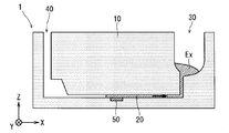
- FIG. 1 is a schematic cross-sectional view illustrating a schematic configuration of a microfluidic chip according to an embodiment.
- FIG. 2 is a diagram illustrating the movement of the test solution in the microfluidic chip according to the embodiment.
- FIG. 3 is a diagram illustrating the movement of the test liquid in the microfluidic chip according to the embodiment.
- FIG. 4 is a diagram illustrating the movement of the test solution in the microfluidic chip according to the embodiment.
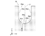
- FIG. 5 is a schematic cross-sectional view showing the structure of the mixing tank according to one embodiment.
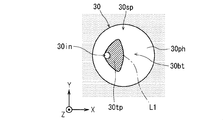
- FIG. 6 is a schematic plan view showing the structure of the mixing tank according to one embodiment.
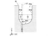
- Drawing 7 is a figure for explaining the structure of the mixing tank concerning one embodiment.
- FIG. 1 is a schematic cross-sectional view illustrating a schematic configuration of a microfluidic chip according to an embodiment.
- FIG. 2 is a diagram illustrating the movement of the test solution in the microfluidic chip according to the embodiment.
- FIG. 3
- FIG. 8 is a diagram for explaining the convection of the test liquid in the mixing tank according to the embodiment.
- FIG. 9 is a diagram for explaining the structure of the mixing tank according to the comparative example.
- FIG. 10 is a diagram for explaining the convection of the test liquid in the mixing tank according to the comparative example.
- FIG. 11 is a diagram schematically illustrating the behavior of the test solution in the mixing tank according to the embodiment.
- FIG. 12 is a diagram schematically illustrating the behavior of the test solution in the mixing tank according to the embodiment.
- FIG. 13 is a diagram schematically illustrating the behavior of the test solution in the mixing tank according to the embodiment.
- FIG. 14 is a diagram schematically illustrating the behavior of the test solution in the mixing tank according to the embodiment.
- FIG. 15 is a diagram schematically illustrating the behavior of the test solution in the mixing tank according to the embodiment.
- FIG. 16 is a diagram schematically illustrating the behavior of the test solution in the mixing tank according to the embodiment.
- FIG. 17 is a schematic cross-sectional view illustrating the structure of the mixing tank according to the first modification.
- FIG. 18 is a view for explaining the structure of the mixing tank according to the first modification.
- FIG. 19 is a diagram schematically illustrating the behavior of the test solution in the mixing tank according to the first modification.
- FIG. 20 is a diagram schematically illustrating the behavior of the test liquid in the mixing tank according to the first modification.
- FIG. 21 is a diagram schematically illustrating the behavior of the test liquid in the mixing tank according to the first modification.
- FIG. 22 is a diagram schematically illustrating the behavior of the test liquid in the mixing tank according to the first modification.
- FIG. 23 is a diagram schematically illustrating the behavior of the test solution in the mixing tank according to the first modification.
- FIG. 24 is a diagram schematically illustrating the behavior of the test liquid in the mixing tank according to the first modification.
- FIG. 25 is a diagram schematically illustrating the behavior of the test liquid in the mixing tank according to the first modification.
- FIG. 26 is a diagram schematically illustrating the behavior of the test solution in the mixing tank according to the first modification.
- FIG. 27 is a diagram schematically illustrating the behavior of the test liquid in the mixing tank according to the first modification.
- FIG. 28 is a diagram schematically illustrating the behavior of the test liquid in the mixing tank according to the first modification.
- FIG. 29 is a schematic plan view showing the structure of the mixing tank according to the second modification.
- FIG. 30 is a schematic plan view showing the structure of the mixing tank according to the second modification.
- FIG. 31 is a schematic diagram showing a schematic configuration of a microfluidic chip according to a third modification.
- FIG. 32 is a schematic diagram showing how the microfluidic chip according to the third modification is used.
- FIG. 33 is a schematic diagram showing how the microfluidic chip according to the third modification is used.
- FIG. 34 is a schematic diagram showing how the microfluidic chip according to the third modification is used.
- FIG. 35 is a schematic diagram showing a schematic configuration of a microfluidic chip according to a fourth modification.
- FIG. 36 is a schematic diagram showing how the microfluidic chip according to the fourth modification is used.
- FIG. 37 is a schematic diagram showing how the microfluidic chip according to the fourth modification is used.
- FIG. 38 is a schematic diagram showing how the microfluidic chip according to the fourth modification is used.
- FIG. 1 is a schematic cross-sectional view showing a schematic configuration of a microfluidic chip 1 according to an embodiment.
- three axes XYZ orthogonal to each other are attached for the purpose of clarifying the azimuth relation.
- the microfluidic chip 1 supplies, for example, a liquid to a microchannel having a width and depth of several ⁇ m to several hundred ⁇ m, and performs mixing and reaction of the liquid based on the behavior of molecules and particles constituting the liquid. It is.
- the microfluidic chip 1 includes a block-shaped main body 10, a microchannel 20 that extends linearly in the main body 10, and a mixture that promotes mixing of the test solution that flows through the microchannel 20.
- the main body 10 is made of a resin such as polycarbonate or polypropylene, and has a size of about 50 mm in width, 50 mm in depth, and about 10 mm in height, for example.
- a plurality of portions constituting the main body portion 10 are separately formed by cutting or injection molding, and the plurality of portions are joined by an adhesive or the like, whereby the main body portion 10 is completed.
- the fine channel 20 has a size of, for example, a width of 1 to 3 mm and a height of several tens of ⁇ m to 1 mm, but is not limited thereto.
- the flow path length is not particularly limited, but the present invention works more effectively when the flow of the test solution in the fine flow path 20 becomes a laminar flow depending on the flow path conditions (size, etc.). Bring effect.
- the mixing tank 30 is provided so as to communicate with one end of the fine channel 20 and functions as a micro mixer (micromixer) that mixes and stirs the test liquid injected into the mixing tank 30.
- the mixing tank 30 has a volume that is equal to or greater than the prescribed amount of the test solution.
- this mixing tank 30 has a structure where mixing and stirring of a test liquid are easy to be accelerated
- the injection / discharge port 40 is provided so as to communicate with the other end of the fine channel 20.
- the injection / discharge port 40 is connected with a supply source of a test solution and a pump for injecting and discharging the test solution.
- a pump that injects the test solution from the injection / discharge port 40 and discharges the test solution from the injection / discharge port 40 may be connected to the mixing tank 30.
- the reaction unit 50 is provided at the lower position of the fine channel 20 at an intermediate position of the portion of the fine channel 20 where the mixing tank 30 and the inlet / outlet port 40 communicate with each other. And in the reaction part 50, the biochemical substance which has spread
- the test solution include plasma obtained by centrifuging blood collected from a living body, and biochemical substances contained in the test solution include various antigens present in blood. Is mentioned.
- the antibody etc. which can react specifically with respect to the said antigen are mentioned, for example.
- ⁇ (2) Rough flow of test solution in microfluidic chip> 2 to 4 are diagrams for explaining the rough flow of the test liquid Ex in the microfluidic chip 1.
- the test liquid Ex is injected into the fine channel 20 from the outside of the microfluidic chip 1 through the injection / discharge port 40, and the test solution Ex is injected into the fine channel. 20 is injected into the mixing tank 30. Then, as shown in FIG. 3, the test solution Ex is once stored in the mixing tank 30. Next, as shown in FIG. 4, the test solution Ex stored in the mixing tank 30 passes through the fine channel 20 and is discharged from the injection / discharge port 40 to the outside of the microfluidic chip 1.
- test solution Ex reacts in the reaction unit 50 during a period from injection to discharge of the test solution Ex with respect to the microfluidic chip 1. Specifically, when the test liquid Ex moves from the injection / discharge port 40 to the mixing tank 30 and when it moves from the mixing tank 30 to the injection / discharge port 40, the test liquid Ex reacts in the reaction unit 50. .
- the concentration of the biochemical substance in the vicinity of the reaction unit 50 in the test solution Ex is reduced by the reaction with the reaction unit 50.
- the concentration of the biochemical substance flowing in the upper part of the microchannel 20 is relatively high in the test liquid Ex due to the reaction with the reaction unit 50.
- the test liquid is divided into a test liquid having a relatively high concentration (high concentration test liquid) and a test liquid having a relatively low concentration of the biochemical substance flowing in the lower part of the fine channel 20 (low concentration test liquid).
- the mixing tank 30 has a structure in which the test liquid Ex is easily mixed and stirred.
- test liquid Ex as a mixed liquid generated by mixing the high-concentration test liquid and the low-concentration test liquid in the mixing tank 30 is discharged from the mixing tank 30, It reacts with the reaction part 50 provided in the vicinity of the lower inner wall surface.
- an immune reaction between the antigen and the antibody is measured by detecting a change in the optical characteristics of the solid-phased surface of the reaction unit 50 from the outside.
- an optical device may be used, or visual observation with the naked eye may be used. If the material of the main body 10 is made of a transparent resin or the like, observation from the outside is easy.
- FIG. 5 is a schematic cross-sectional view showing the structure of the mixing tank 30, and FIG. 6 is a schematic top view showing the structure of the mixing tank 30.
- FIG. 5 the cross section (XZ cross section) parallel to the XZ plane of the mixing tank 30 is shown, and the figure which looked at the mixing tank 30 from + Z direction is shown in FIG.
- the mixing tank 30 is a tank part in which the upper side (+ Z direction) is opened and the liquid inlet 30in is provided in the bottom part 30bt.
- the space (internal space region) 30sp surrounded by the inner wall of the mixing tank 30 is such that the shape of the cross section (XY cross section) parallel to the plane perpendicular to the Z axis except for the vicinity of the liquid inlet 30in is substantially circular. It is formed. From another point of view, the internal space region 30sp has a shape that is rotationally symmetric in all directions around the axis L1 parallel to the Z axis except for the vicinity of the liquid inlet 30in.
- the axis L1 is a straight line penetrating the center of gravity of each XY cross section of the internal space region 30sp in the vertical direction (Z-axis direction) excluding the vicinity of the liquid inlet 30in. Below, this axis
- shaft L1 is also called the line (center line) which shows the center of the mixing tank 30.
- centroid positions of the plurality of XY cross sections in the internal space region 30sp do not lie on one straight line, approximate the centroid positions of the plurality of XY cross sections by approximation calculation from the centroid positions of the plurality of XY cross sections.
- a straight line that penetrates the center line L1 may be obtained.
- side surface (side wall portion) 30sw of the inner wall of the mixing tank 30 forming the internal space region 30sp constitutes a wall surface substantially parallel to the Z axis.
- the liquid inlet 30in is provided at a position shifted from the axis L1 in the ⁇ X direction in the bottom 30bt of the mixing tank 30.
- the liquid inlet 30 in is communicated with the fine flow path 20. For this reason, the test liquid Ex is injected from the fine channel 20 into the internal space region 30sp through the liquid injection port 30in. Since the flow path connecting the liquid injection port 30in and the fine flow path 20 extends in the direction along the Z axis, the flow of the test liquid Ex injected from the liquid injection port 30in to the internal space region 30sp is reduced.
- the direction is the + Z direction.
- the liquid inlet 30in also serves to discharge the test liquid Ex stored in the mixing tank 30 toward the fine channel 20.
- the bottom portion 30bt is a portion where the XY cross section of the internal space region 30sp becomes narrower as it goes downward ( ⁇ Z direction). Specifically, the closer to the liquid inlet 30in, the narrower the XY cross section of the internal space region 30sp of the bottom 30bt.
- the liquid inlet 30in is provided at a position shifted from the center of the bottom 30bt.
- the center of the bottom portion 30bt referred to here is a portion of the bottom portion 30bt through which a straight line passing through the center of gravity of a planar region obtained by projecting the bottom portion 30bt on the XY plane passes in the vertical direction (Z-axis direction).
- the center of the bottom portion 30bt may be a portion through which an approximate straight line passing through the center of gravity of a plurality of XY cross sections of the space region formed by the bottom portion 30bt in the inner space region 30sp in the vertical direction (Z-axis direction) passes.
- the center of the bottom portion 30bt is substantially the same as the portion through which the axis L1 passes.
- the bottom 30bt has a liquid inlet 30in, a liquid reservoir 30ph, and an inclined portion 30tp.
- the liquid reservoir 30ph is a portion that forms a substantially semispherical space convex downward.
- the inclined portion 30tp has a substantially constant inclination from the portion in the vicinity of the point through which the axis L1 passes toward the liquid inlet 30in.
- the inclined portion 30 tp has a fan-shaped surface (shaded portion in FIG. 6) that requires the liquid inlet 30 in when viewed from above (+ Z direction). Configured. That is, the inclined portion 30tp tapers toward the liquid inlet 30in. In addition, the inclined portion 30tp has a form in which a constant inclination is maintained regardless of which direction the liquid inlet 30in is used as a reference.
- Existence of the test liquid Ex in the mixing tank 30 is suppressed because the discharge of the test liquid Ex from the liquid inlet 30in is promoted by the presence of the inclined portion 30tp. And if a liquid becomes difficult to remain in the mixing tank 30, wasteful use of the test liquid Ex is also suppressed.
- both the curved surfaces of the inclined portion 30tp and the liquid reservoir 30ph are discontinuous at the boundary between the inclined portion 30tp and the liquid reservoir 30ph, and a portion corresponding to a convex portion that gently protrudes is formed near the boundary.
- FIG. 7 is a diagram for explaining the structure of the mixing tank 30 from another viewpoint.
- a cross section (XZ cross section) parallel to the XZ plane of the mixing tank 30 is shown.
- a line (virtual line) L2 that passes through the center of the liquid inlet 30in and virtually extends upward (+ Z direction) is attached.
- the distance D1 from the imaginary line L2 to the inner wall surface of the mixing tank 30 in the ⁇ X direction and the inner wall surface of the mixing tank 30 in the + X direction from the imaginary line L2 Is different from the distance D2.
- the distance D2 to the inner wall in the direction opposite to the one direction (for example, + X direction) is different.
- the inner wall of the mixing tank 30 is directed toward the -X direction with respect to the liquid inlet 30in as the liquid inlet 30in.
- the side wall portion 30sw extending in the vertical direction is reached in response to a relatively short change in the X coordinate, as compared to the case of moving in the + X direction with reference to.
- the predetermined amount in the + X direction focusing on the amount of change in the angle (inner wall angle change) that the inner wall of the mixing tank 30 forms with the horizontal plane (XY plane), when the position of the liquid inlet 30in is used as a reference, the predetermined amount in the + X direction.
- the inner wall angle change amount with respect to the movement of the distance is different from the inner wall angle change amount with respect to the movement of the predetermined distance in the ⁇ X direction.
- the first change amount and the second change amount defined below are different.
- the first change amount is a predetermined distance in the first direction (for example, the ⁇ X direction) from the liquid inlet 30in on the inner wall surface of the mixing tank 30 from the bottom 30bt to the side wall 30sw. This corresponds to the amount by which the angle formed by the inner wall surface and the horizontal plane (in this case, the XY plane) changes in the traveling path.
- the second amount of change is the second direction opposite to the first direction from the liquid injection port 30in (for example, from the bottom 30bt to the side wall 30sw on the inner wall surface of the mixing tank 30 (for example, This corresponds to the amount by which the angle formed by the inner wall surface and the horizontal plane (in this case, the XY plane) changes along a path that travels a predetermined distance in the + X direction.
- the liquid inlet 30in is provided at a position shifted in the first direction from the center of the bottom 30bt, and in the second direction based on the liquid inlet 30in of the bottom 30bt of the mixing tank 30.
- An inclined portion 30tp is provided.
- the first change amount is relatively larger than the second change amount.
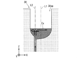
- FIG. 8 is a diagram for explaining the convection of the test liquid Ex injected into the internal space region 30sp from the liquid injection port 30in.
- the rough flow of the high-concentration test solution and the low-concentration test solution is shown by the thick arrows.
- the liquid inlet 30in is provided at a position shifted from the center line L1 of the mixing tank 30 and at a position shifted from the center of the bottom 30bt. For this reason, in the internal space region 30sp, the space region on the ⁇ X side with reference to the virtual line L2 is narrower than the space region on the + X side with reference to the liquid inlet 30in.
- the test solution Ex high concentration test solution
- the test solution Ex low concentration test solution
- the test solution Ex injected from the + X side portion of the liquid inlet 30in once flows into the ⁇ X side space region of the internal space region 30sp.
- the high concentration test solution easily flows into the + X side space region of the internal space region 30sp.
- the flow of the high concentration test solution merges with the flow of the test solution Ex (low concentration test solution) injected from the + X side portion of the liquid injection port 30in into the + X side space region of the internal space region 30sp. It is easy to be done.
- the structure of the mixing tank 30 causes convection of the test liquid Ex in which the high-concentration test liquid and the low-concentration test liquid are easily mixed and stirred. At this time, the flow of the test solution Ex in the internal space region 30sp tends to be turbulent.
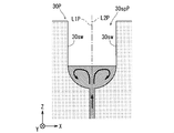
- the liquid inlet 30inP is provided on the center line L1P of the mixing tank 30P and at the center of the bottom 30btP.
- the center line L1P of the mixing tank 30P and the virtual line L2P extending in the + Z direction from the center of the liquid inlet 30inP are the same. Therefore, in the internal space region 30spP of the mixing tank 30P, the distance DP from the virtual line L2P to the inner wall at an arbitrary position of the mixing tank 30P is substantially constant in each XY cross section.
- FIG. 10 is a diagram for explaining the convection of the test liquid Ex injected from the liquid inlet 30inP into the internal space region 30spP.
- a rough flow of the high-concentration test solution and the low-concentration test solution is shown by thick arrows.
- a space region in the ⁇ X direction with reference to the liquid inlet 30inP, and a space region in the + X direction with reference to the liquid inlet 30inP Have substantially the same area.
- the test solution Ex high concentration test solution
- the test solution Ex low concentration test solution
- the test solution Ex injected from the + X side portion of the liquid injection port 30inP flows into the + X side space region of the internal space region 30spP. Therefore, compared with the case of the mixing tank 30 according to the present embodiment shown in FIG. 8, convection that promotes mixing and stirring of the high concentration test solution and the low concentration test solution is relatively unlikely to occur. .
- the high-concentration test liquid and the low-concentration liquid also depend on the behavior of the test liquid Ex at a stage (initial injection stage) soon after the test liquid Ex starts to be injected into the mixing tank 30. Mixing and stirring with the test solution is facilitated.
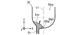
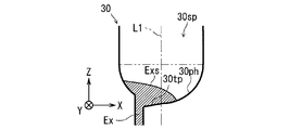
- FIGS. 11 to 16 are schematic diagrams showing the state of the test solution Ex in the mixing tank 30 at the initial injection stage.
- the shape of the inner edge of the XZ cross section near the bottom 30bt of the mixing tank 30 is drawn with a bold line, and the shape of the XZ cross section of the liquid level Exs of the test liquid Ex is drawn with a solid line.
- the behavior of the test liquid Ex in the mixing tank 30 in the initial stage of injection will be described with reference to FIGS.
- test solution Ex sequentially shows the following behaviors (I) to (VI) in the mixing tank 30.
- the shape of the liquid level Exs is concave.
- a portion in the vicinity of the liquid level Exs of the test liquid Ex shakes violently.
- a turbulent flow is generated in the vicinity of the liquid level Exs of the test liquid Ex, and the mixing and stirring of the test liquid Ex are promoted.
- the microfluidic chip 1 As described above, according to the microfluidic chip 1 according to the present embodiment, when the high concentration test liquid and the low concentration test liquid are injected into the mixing tank 30 at the same time, the high concentration test liquid is mixed in the mixing tank 30. And a low-concentration test solution are easily mixed. For this reason, two or more types of liquids are efficiently mixed with a simple configuration.
- the wettability of the test liquid Ex to the surface of the inner wall of the mixing tank 30 Is preferably low. That is, it is preferable that the contact angle of the test liquid Ex resulting from the surface tension can be increased with respect to the surface of the inner wall of the mixing tank 30.
- the surface of the inner wall of the mixing tank 30 may be processed so as to have water repellency, and the processing is realized by various coatings using fluorine or the like.
- test liquid Ex stored in the mixing tank 30 is discharged from the liquid inlet 30in provided in the bottom 30bt of the mixing tank 30. For this reason, the residue of the test liquid Ex in the mixing tank 30 is suppressed with a simple configuration, and as a result, wasteful use of the test liquid Ex is suppressed.
- the bottom portion 30bt of the mixing tank 30 is provided with the inclined portion 30tp that tapers toward the liquid injection port 30in, so that a convex portion is formed at the boundary between the inclined portion 30tp and the liquid reservoir portion 30ph.
- a large number of convex portions may be formed by providing a plurality of curved concaves on one side of the liquid inlet without providing an inclined portion at the bottom of the mixing tank. That is, it is sufficient that at least one convex portion is provided at the bottom of the mixing tank.
- a specific example in which a large number of convex portions are formed at the bottom of the mixing tank will be described.
- FIG. 17 is a schematic cross-sectional view showing the structure of a mixing tank 30A in which a large number of sharp parts 30pr are provided on the bottom part 30btA.
- the cross section (XZ cross section) parallel to the XZ plane of the mixing tank 30 is shown.
- the mixing tank 30 ⁇ / b> A is a tank part in which the upper side (+ Z direction) is opened and the liquid inlet 30 in A is provided in the bottom part 30 btA.
- the space (internal space region) 30spA surrounded by the inner wall of the mixing tank 30A is rotationally symmetric with respect to all directions around the axis L1A parallel to the Z axis except for the space region surrounded by the bottom 30btA.
- a shape having a shape and a cross section (XY cross section) parallel to a plane perpendicular to the Z axis is formed to be substantially circular.
- the axis L1A is a straight line passing through the center of gravity of each XY cross section of the space area excluding the space area surrounded by the bottom 30btA of the internal space area 30spA in the vertical direction (Z-axis direction). This corresponds to 30 center lines.
- the centroid positions of the plurality of XY cross sections of the space area that is not surrounded by the bottom portion 30btA of the internal space area 30spA do not ride on one straight line, from the centroid positions of the plurality of XY cross sections, A straight line that approximately passes through the centroid positions of the plurality of XY cross sections may be obtained as the center line L1A by the approximate calculation.
- the side surface (side wall portion) 30swA of the inner wall of the mixing tank 30A that forms a space region that is not surrounded by the bottom portion 30btA in the inner space region 30sp constitutes a wall surface substantially parallel to the Z axis.
- the liquid inlet 30inA is provided at a position shifted in the ⁇ X direction from the center line L1A in the bottom 30btA of the mixing tank 30A.
- the liquid inlet 30inA communicates with the fine flow path 20, and the test liquid Ex is injected in the + Z direction from the fine flow path 20 to the internal space region 30spA via the liquid inlet 30inA.
- the liquid inlet 30inA also serves to discharge the test liquid Ex stored in the mixing tank 30A toward the fine channel 20.
- the bottom 30btA is a portion where the XY cross section of the internal space region 30spA becomes narrower as it goes downward ( ⁇ Z direction). Specifically, the closer to the liquid inlet 30inA, the narrower the XY cross section of the internal space region 30spA of the bottom 30btA.
- the liquid inlet 30inA is provided at a position shifted from the center of the bottom 30btA. Note that the center of the bottom portion 30btA referred to here is a portion of the bottom portion 30btA through which a straight line passing through the center of gravity of a planar region obtained by projecting the bottom portion 30btA on the XY plane passes in the vertical direction (Z-axis direction).
- the bottom portion 30btA has a liquid inlet 30inA and a multi-step portion 30st, and as shown in FIG. 17, the multi-step portion 30st has four sharp portions 30pr.
- a recessed portion that is recessed in a curved surface is formed between the liquid inlet 30inA and the first-stage sharp portion 30pr. Also, between the first stage sharp part 30pr and the second stage sharp part 30pr, between the second stage sharp part 30pr and the third stage sharp part 30pr, and the third stage sharp part 30pr and 4pr. A recessed portion that is recessed in a curved surface is formed between the sharp portion 30pr of the step. Then, the Z coordinate of the position to be arranged becomes larger in the order of the first to fourth stage sharp portions 30pr.
- the sharp portion 30pr is configured so that the angle formed with respect to the horizontal plane changes abruptly. For this reason, any curved surface constituting the multi-step portion 30st is discontinuous at the sharp portion 30pr, and a portion corresponding to a gently projecting convex portion is formed in the vicinity of the sharp portion 30pr.
- FIG. 18 is a diagram for explaining the structure of the mixing tank 30A from another viewpoint.
- a cross section (XZ cross section) parallel to the XZ plane of the mixing tank 30A is shown.
- a line (virtual line) L2A that passes through the center of the liquid inlet 30inA and is virtually extended upward (+ Z direction) is attached.
- the mixing tank 30 ⁇ / b> A according to this modification has the following structure, similarly to the mixing tank 30 according to the above embodiment.
- the distance D1A from the imaginary line L2A to the inner wall of the mixing tank 30A in the -X direction and the mixing tank 30A in the + X direction from the imaginary line L2A is different.
- the distance D1A from the position through which the virtual line L2A passes to the inner wall in one direction here, the ⁇ X direction
- the distance D2A to the inner wall in the direction opposite to one direction tends to be different. Specifically, the distance D2A tends to be larger than the distance D1A.
- the liquid inlet 30inA according to the present modification is provided at a position shifted from the center line L1A of the mixing tank 30A and the center of the bottom 30btA. It is provided at a position deviated from. Therefore, in the internal space region 30spA, the space region on the ⁇ X side with reference to the virtual line L2A is narrower than the space region on the + X side with reference to the liquid inlet 30inA.
- the test solution Ex high concentration test solution
- the test solution Ex low concentration test solution
- the test solution Ex injected from the + X side portion of the liquid injection port 30inA is included in the internal space region 30spA.
- the high concentration test solution easily flows into the + X side space region of the internal space region 30spA.
- the flow of the high concentration test solution merges with the flow of the test solution Ex (low concentration test solution) injected from the + X side portion of the liquid injection port 30inA into the + X side space region of the internal space region 30spA. It is easy to be done.
- the structure of the mixing tank 30A causes convection of the test liquid Ex in which the high-concentration test liquid and the low-concentration test liquid are easily mixed and stirred. At this time, the flow of the test solution Ex in the internal space region 30spA tends to be turbulent.
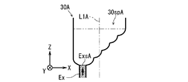
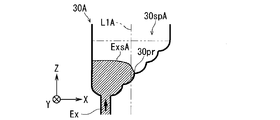
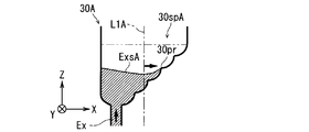
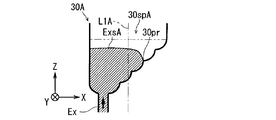
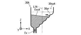
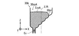
- 19 to 28 are schematic diagrams showing the state of the test solution Ex in the mixing tank 30A at the initial stage of injection.
- the shape of the inner edge of the XZ cross section near the bottom 30btA of the mixing tank 30A is drawn with a bold line, and the XZ cross section of the liquid surface ExsA of the test liquid Ex is drawn with a solid line.
- the behavior of the test liquid Ex in the mixing tank 30A in the initial stage of injection will be described with reference to FIGS.
- test solution Ex sequentially shows the following behaviors (A) to (E) in the mixing tank 30A.
- the foremost portion of the test liquid Ex extends from the fine channel 20 to the liquid inlet 30inA of the mixing tank 30A. Then, until the liquid level ExsA of the test liquid Ex reaches the first-stage sharp point 30pr, as shown in FIG. 20, the liquid level ExsA is virtually in the + Z direction from the center of the liquid inlet 30inA. It moves in the + Z direction while maintaining a state substantially orthogonal to the extending virtual line L2A. That is, the liquid injection port 30inA has a shape that is rotationally symmetric with respect to all directions around the virtual line L2A.
- the internal space region 30sp has a shape that is rotationally symmetric in all directions around the center line L1 parallel to the Z axis except for the vicinity of the liquid inlet 30in. It is not limited to this.
- the internal space region 30sp may be reduced or enlarged in the direction along the X axis or the Y axis. That is, the XY cross section of the internal space region 30sp excluding the vicinity of the liquid inlet 30in is not circular and may have various shapes.
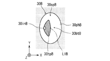
- FIG. 29 is a schematic diagram showing the structure of a mixing tank 30B in which the mixing tank 30 according to the embodiment is reduced in the direction along the X axis.
- the mixing tank 30B forms an internal space region 30spB.
- the bottom 30btB of the mixing tank 30B has a liquid inlet 30inB, an inclined portion 30tpB, and a liquid reservoir 30phB.
- the internal space region 30spB has an elliptical columnar shape centered on an axis L1B parallel to the Z axis, except for the space region surrounded by the bottom 30btB.
- FIG. 30 is a schematic diagram showing the structure of a mixing tank 30C in which the mixing tank 30 according to the embodiment is reduced in the direction along the Y axis.
- the mixing tank 30C forms an internal space region 30spC.
- the bottom 30btC of the mixing tank 30C has a liquid inlet 30inC, an inclined portion 30tpC, and a liquid reservoir 30phC.
- the internal space region 30spC has an elliptical columnar shape centered on an axis L1C parallel to the Z axis, except for the space region surrounded by the bottom portion 30btC.
- test liquid Ex is injected into the fine channel 20 from the injection / discharge port 40, and two types of high-concentration test solution and low-concentration test solution are generated by the reaction in the reaction unit 50 of the fine channel 20.
- the test liquid was generated, it is not limited to this.
- an introduction part into which two different types of liquids (A liquid and B liquid) are respectively introduced may be provided upstream of the fine channel 20.
- a liquid and B liquid two different types of liquids
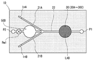
- FIG. 31 is a schematic diagram showing a schematic configuration of a microfluidic chip 1D according to a third modification.
- FIG. 31 shows a rough arrangement of each part when the microfluidic chip 1D is viewed from above.
- the microfluidic chip 1D includes an A liquid introduction part InA, a B liquid introduction part InB, an A liquid supply path 21A, a B liquid supply path 21B, a fine flow path 22, a mixing tank 30, and a reaction tank part. 50D, 1st pump connection part P1, and 2nd pump connection part P2 are provided.
- the A liquid introduction part InA is provided so as to communicate with the fine flow path 22 via the A liquid supply path 21A.
- a supply source of A liquid is connected to the A liquid introducing unit InA. For this reason, the A liquid introduced in the A liquid introduction part InA is supplied to the fine flow path 22 via the A liquid supply path 21A.
- the B liquid introduction part InB is provided so as to communicate with the fine flow path 22 via the B liquid supply path 21B.
- a B liquid supply source is connected to the B liquid introduction unit InB. For this reason, B liquid introduce
- the portion where the A liquid supply path 21A is connected to the fine flow path 22 and the portion where the B liquid supply path 21B is connected to the fine flow path 22 are arranged close to each other. Is done.
- the fine flow path 22 is a portion corresponding to the fine flow path 20 according to the above-described embodiment, and one end portion of the fine flow path 22 communicates with the mixing tank 30 via a predetermined flow path.
- the mixing tank 30 is the same part as the mixing tank 30 according to the above embodiment.
- the reaction tank unit 50D is a container provided with a reaction unit corresponding to the reaction unit 50 according to the above-described embodiment, and communicates with the other end of the microchannel 22.
- the first pump connection portion P1 communicates with the mixing tank 30 and is connected to a pump (liquid feeding pump) for feeding liquid to the mixing tank 30.
- the second pump connection part P2 communicates with the reaction tank part 50D and is connected to a pump (liquid supply pump) for sending liquid to the reaction tank part 50D.
- FIGS. 32 to 34 are diagrams for explaining the flow of the liquid during the inspection using the microfluidic chip 1D.
- the following steps (a) to (c) are sequentially performed, so that it is possible to detect a liquid reaction and its reaction result with a simple configuration.
- the reaction in the reaction tank 50D may be such that the biochemical substance reacts similarly to the reaction in the reaction unit 50 according to the above embodiment, or may be any other reaction. Moreover, there is no special restriction
- the microfluidic chip 1D is mounted on a dedicated device when the mixed liquid LAB is reacted in the reaction tank 50D. For this reason, various configurations for detecting the reaction result may be included in the dedicated device.
- reaction result may be detected by removing the microfluidic chip 1D from the dedicated device and mounting the microfluidic chip 1D on another analysis device. Further, the reaction result may be detected by a human by visually observing the mixing tank portion 50D of the microfluidic chip 1D.
- various optical members such as lenses, waveguides, and prisms for assisting detection of optical characteristics may be provided in the microfluidic chip 1D.
- the liquid A and the liquid B are mixed once by injecting the liquid A and the liquid B into the mixing tank 30.
- the present invention is not limited to this.
- two or more mixing tanks 30 may be provided in the microfluidic chip.
- a specific example will be described.
- FIG. 35 is a schematic diagram showing a schematic configuration of a microfluidic chip 1E according to a fourth modification.
- FIG. 35 shows a rough arrangement of each part when the microfluidic chip 1E is viewed from above.
- the microfluidic chip 1E according to the fourth modified example has a reaction tank unit 50D replaced with a mixing tank 30 as compared with the microfluidic chip 1D according to the third modified example,
- the reaction part 50 is provided on the lower surface of the fine channel 22. Since other configurations are the same, the same reference numerals are given and description thereof is omitted as appropriate.
- the right mixing tank 30 in FIG. 35 is referred to as a first mixing tank 30, and the left mixing tank 30 is referred to as a second mixing tank 30.
- 36 to 38 are diagrams for explaining the flow of the liquid during the inspection using the microfluidic chip 1E.
- the following steps (A) to (F) are sequentially performed, so that the liquid reaction and the reaction result can be detected with a simple configuration.
- the reaction unit 50E sufficiently reacts with the mixed solution LAB, and the reaction result is detected. Furthermore, the reaction with the mixed solution LAB may be sufficiently performed in the reaction section 50E by repeating the steps (C) to (F) a plurality of times.
- the test liquid Ex is injected from the fine channel 20 into the mixing tank 30 in the + Z direction, but is not limited thereto.
- the flow path (connection flow path) connecting the fine flow path 20 and the mixing tank 30 may be slightly inclined with respect to the Z axis. However, if the connecting flow path is inclined so that the test liquid Ex can easily flow on the inclined portion 30tp, the amount of occurrence of the fluctuation of the liquid level Exs using the surface tension is reduced. For this reason, it is preferable that the connection flow path extends along the vertical direction (+ Z direction) or is inclined in the direction opposite to the inclined portion 30tp.
- the direction (injection direction) in which the test liquid Ex is injected from the liquid inlet 30in into the internal space region 30sp is horizontal (here, The direction closer to the vertical direction (here, the + Z direction) is more preferable than the + X direction.
- the inner wall surface of the mixing tank 30 is mainly configured by a curved surface.
- the present invention is not limited to this.
- the inner wall surface of the mixing tank may be mainly configured by a combination of flat surfaces.
- the dent portion is constituted by a curved surface, rather than the dent portion constituting the bottom portion of the mixing tank being constituted by a combination of planes.
- the upper part of the mixing tank 30 except the bottom 30bt has a shape that is rotationally symmetric about the axis L1, but this is not restrictive.
- the aspect which has various shapes, such as the upper part except the bottom part 30bt of the mixing tank 30, meandering is also considered.
- the relationship between the volume of the mixing tank 30 and the volume of liquid injected into the mixing tank 30 was not particularly mentioned.
- the volume of the mixing tank 30 is injected into the mixing tank 30 from the viewpoint of sufficient liquid mixing utilizing the structure of the mixing tank 30 and no increase in the size of the microfluidic chip 1.
- An example in which the volume is about 1 to 1.5 times the volume of the liquid to be produced can be considered.
- the liquid mixed in the mixing tank 30 is two types of liquids, liquid A and liquid B, but is not limited to this, and may be two or more liquids. It ’s fine.
Landscapes
- Chemical & Material Sciences (AREA)
- Chemical Kinetics & Catalysis (AREA)
- Automatic Analysis And Handling Materials Therefor (AREA)
- Micromachines (AREA)
- Physical Or Chemical Processes And Apparatus (AREA)
Abstract
Description
図1は、一実施形態に係るマイクロ流体チップ1の概略構成を示す断面模式図である。図1および図1以降のその他の図には、方位関係を明確化することを目的として、相互に直交するXYZの3軸が付されている。
図2から図4は、マイクロ流体チップ1における試験液Exの大まかな流れを説明するための図である。
図5は、混合槽30の構造を示す断面模式図であり、図6は、混合槽30の構造を示す上面模式図である。なお、図5では、混合槽30のXZ平面に平行な断面(XZ断面)が示され、図6では、混合槽30を+Z方向から見た図が示されている。
図8は、液体注入口30inから内部空間領域30spに注入される試験液Exの対流について説明するための図である。図8では、太線の矢印によって、高濃度試験液および低濃度試験液の大まかな流れが示されている。
本実施形態に係る混合槽30の構造によれば、混合槽30に試験液Exが注入され始めて間もない段階(注入初期段階)における試験液Exの挙動によっても、高濃度試験液と低濃度試験液との混合および攪拌が促進される。
なお、本発明は上述の実施の形態に限定されるものではなく、本発明の要旨を逸脱しない範囲において種々の変更、改良等が可能である。
上記一実施形態では、混合槽30の底部30btに、液体注入口30inに向けて先細りする傾斜部30tpが設けられることで、傾斜部30tpと液溜部30phとの境界に凸部が形成されていたが、これに限られない。例えば、混合槽の底部において、傾斜部が設けられることなく、液体注入口の片側に曲面状の多数の凹みが多段的に設けられることで、多数の凸部が形成されても良い。すなわち、混合槽の底部に少なくとも1つの凸部が設けられれば良い。以下、混合槽の底部に多数の凸部が形成される具体例を示して説明する。
図17は、底部30btAに多数の尖鋭部30prが設けられた混合槽30Aの構造を示す断面模式図である。なお、図17では、混合槽30のXZ平面に平行な断面(XZ断面)が示されている。
上述したように、上記一実施形態に係る液体注入口30inと同様に、本変形例に係る液体注入口30inAは、混合槽30Aの中心線L1Aからずれた位置に設けられるとともに、底部30btAの中央からずれた位置に設けられる。このため、内部空間領域30spAのうち、仮想線L2Aを基準とした-X側の空間領域が、液体注入口30inAを基準とした+X側の空間領域よりも狭い。
混合槽30Aの構造によれば、混合槽30Aに試験液Exが注入され始めて間もない段階(注入初期段階)における試験液Exの挙動においても、高濃度試験液と低濃度試験液との混合および攪拌が促進される。
上記一実施形態では、内部空間領域30spが、液体注入口30inの近傍を除いてZ軸に平行な中心線L1を中心とした全方向について回転対称となるような形状を有していたが、これに限られない。例えば、内部空間領域30spがX軸またはY軸に沿った方向に縮小または拡大されても良い。つまり、液体注入口30inの近傍を除く内部空間領域30spのXY断面は、円形ではなく、種々の形状であっても良い。
上記一実施形態では、注入排出口40から1種類の試験液Exが微細流路20に注入され、微細流路20の反応部50における反応によって高濃度試験液と低濃度試験液の2種類の試験液が生じたが、これに限られない。例えば、微細流路20の上流に異なる2種類の液体(A液およびB液)がそれぞれ導入される導入部が設けられても良い。以下、具体例を示して説明する。
上記第3変形例では、A液およびB液が混合槽30に一度注入されることでA液およびB液の混合が行われたが、これに限られない。例えば、マイクロ流体チップに2以上の混合槽30が設けられても良い。以下、具体例を示して説明する。
◎上記一実施形態では、微細流路20から混合槽30へと試験液Exが+Z方向に注入されたが、これに限られない。微細流路20と混合槽30とを繋ぐ流路(連結流路)が、Z軸に対して若干傾斜されていても良い。但し、傾斜部30tp上に試験液Exが流れ易くなるように連結流路が傾けられると、表面張力を利用した液面Exsの揺れの発生量の低下を招く。このため、連結流路は、垂直方向(+Z方向)に沿って延在するかまたは傾斜部30tpとは反対方向に傾斜されることが好ましい。
20,22 微細流路
21A A液供給路
21B B液供給路
30,30A,30B,30C 混合槽
30bt,30btA,30btB,30btC 底部
30in,30inA,30inB,30inC 液体注入口
30pr 尖鋭部
30tp,30tpB,30tpC 傾斜部
50,50E 反応部
50D 反応槽部
Claims (10)
- 第1および第2液体が流される微細流路と、
前記微細流路に連通される液体注入口が底部に設けられる混合槽と、
を備え、
前記液体注入口が、
前記底部のうちの該底部の中央からずれた位置に設けられることを特徴とするマイクロミキサー。 - 第1および第2液体が流される微細流路と、
前記微細流路と連通される液体注入口が底部に設けられる混合槽と、
を備え、
前記液体注入口が、
前記混合槽の中心線からずれた位置に設けられることを特徴とするマイクロミキサー。 - 第1および第2液体が流される微細流路と、
前記微細流路と連通される液体注入口が底部に設けられる混合槽と、
を備え、
前記混合槽の内壁によって囲まれる内部空間領域の水平方向に沿った断面において、前記液体注入口の中央から上方に仮想的に延伸される仮想線が通る位置から一方向に係る前記内壁までの第1の距離と、前記仮想線が通る位置から前記一方向とは反対方向に係る前記内壁までの第2の距離とが、異なることを特徴とするマイクロミキサー。 - 請求項1から請求項3の何れか1つの請求項に記載のマイクロミキサーであって、
前記混合槽の底部に少なくとも1つの凸部が設けられることを特徴とするマイクロミキサー。 - 請求項1から請求項4の何れか1つの請求項に記載のマイクロミキサーであって、
前記混合槽の内壁面上を前記液体注入口から第1方向に所定距離進む経路において該内壁面と水平面とが成す角度の第1変化量と、前記混合槽の内壁面上を前記液体注入口から前記第1方向とは反対の第2方向に前記所定距離進む経路において該内壁面と前記水平面とが成す角度の第2変化量とが異なることを特徴とするマイクロミキサー。 - 請求項5に記載のマイクロミキサーであって、
前記第1変化量が、
前記第2変化量よりも相対的に大きく、
前記混合槽の底部のうちの前記液体注入口を基準とした前記第2方向に、前記液体注入口に向けて先細りする傾斜部が設けられることを特徴とするマイクロミキサー。 - 請求項1から請求項6の何れか1つの請求項に記載のマイクロミキサーであって、
前記混合槽の内壁の表面が、
撥水性を有することを特徴とするマイクロミキサー。 - 請求項1から請求項7の何れか1つの請求項に記載のマイクロミキサーであって、
前記液体注入口が、
前記混合槽に貯留される液体を前記微細流路に向けて排出することを特徴とするマイクロミキサー。 - 請求項1から請求項8の何れか1つの請求項に記載のマイクロミキサーであって、
前記第1液体を前記微細流路に対して供給する第1供給路と、
前記第2液体を前記微細流路に対して供給する第2供給路と、
を更に備えることを特徴とするマイクロミキサー。 - 請求項1から請求項9の何れか1つの請求項に記載のマイクロミキサーと、
前記混合槽において前記第1および第2液体が混合されることで生成される混合液体が前記混合槽から排出される流路の内壁面近傍に設けられ、前記混合液体に含まれる物質との反応を行う反応物質が固定される反応部と、
を備えることを特徴とするマイクロ流体チップ。
Priority Applications (3)
| Application Number | Priority Date | Filing Date | Title |
|---|---|---|---|
| JP2011525327A JP5062370B2 (ja) | 2010-12-13 | 2010-12-13 | マイクロミキサー、およびマイクロ流体チップ |
| PCT/JP2010/072372 WO2012081072A1 (ja) | 2010-12-13 | 2010-12-13 | マイクロミキサー、およびマイクロ流体チップ |
| US13/395,592 US9120067B2 (en) | 2009-09-25 | 2010-12-13 | Micro mixer and microfluidic chip |
Applications Claiming Priority (1)
| Application Number | Priority Date | Filing Date | Title |
|---|---|---|---|
| PCT/JP2010/072372 WO2012081072A1 (ja) | 2010-12-13 | 2010-12-13 | マイクロミキサー、およびマイクロ流体チップ |
Publications (1)
| Publication Number | Publication Date |
|---|---|
| WO2012081072A1 true WO2012081072A1 (ja) | 2012-06-21 |
Family
ID=46244204
Family Applications (1)
| Application Number | Title | Priority Date | Filing Date |
|---|---|---|---|
| PCT/JP2010/072372 Ceased WO2012081072A1 (ja) | 2009-09-25 | 2010-12-13 | マイクロミキサー、およびマイクロ流体チップ |
Country Status (2)
| Country | Link |
|---|---|
| JP (1) | JP5062370B2 (ja) |
| WO (1) | WO2012081072A1 (ja) |
Cited By (5)
| Publication number | Priority date | Publication date | Assignee | Title |
|---|---|---|---|---|
| WO2014174807A1 (ja) * | 2013-04-25 | 2014-10-30 | パナソニックIpマネジメント株式会社 | 流路デバイスおよびそれを用いた検出方法 |
| WO2016017411A1 (ja) * | 2014-07-29 | 2016-02-04 | コニカミノルタ株式会社 | 成形用金型、成形用金型の製造方法、マイクロミキサー、マイクロミキサーの製造方法、マイクロ流体チップおよびマイクロ流体チップの製造方法 |
| JPWO2015012390A1 (ja) * | 2013-07-26 | 2017-03-02 | 積水メディカル株式会社 | 検体調製用容器 |
| JP2019066321A (ja) * | 2017-09-29 | 2019-04-25 | シスメックス株式会社 | カートリッジ、検出方法、および検出装置 |
| JP2021026003A (ja) * | 2017-02-06 | 2021-02-22 | イーエフエー—エンジニアリング フォー オール エルティーディー. | マイクロミキサー |
Citations (5)
| Publication number | Priority date | Publication date | Assignee | Title |
|---|---|---|---|---|
| JP2005028531A (ja) * | 2003-07-08 | 2005-02-03 | Fuji Electric Systems Co Ltd | マイクロチャンネルチップ |
| JP2005326392A (ja) * | 2004-04-15 | 2005-11-24 | Tama Tlo Kk | 試料導入マイクロデバイス |
| JP2006102649A (ja) * | 2004-10-06 | 2006-04-20 | Hitachi Industries Co Ltd | マイクロ流体装置 |
| JP2007144419A (ja) * | 2006-11-27 | 2007-06-14 | Furukawa Electric Co Ltd:The | マイクロ化学反応装置 |
| WO2009019984A1 (ja) * | 2007-08-07 | 2009-02-12 | Honda Motor Co., Ltd. | 塗装装置 |
-
2010
- 2010-12-13 WO PCT/JP2010/072372 patent/WO2012081072A1/ja not_active Ceased
- 2010-12-13 JP JP2011525327A patent/JP5062370B2/ja active Active
Patent Citations (5)
| Publication number | Priority date | Publication date | Assignee | Title |
|---|---|---|---|---|
| JP2005028531A (ja) * | 2003-07-08 | 2005-02-03 | Fuji Electric Systems Co Ltd | マイクロチャンネルチップ |
| JP2005326392A (ja) * | 2004-04-15 | 2005-11-24 | Tama Tlo Kk | 試料導入マイクロデバイス |
| JP2006102649A (ja) * | 2004-10-06 | 2006-04-20 | Hitachi Industries Co Ltd | マイクロ流体装置 |
| JP2007144419A (ja) * | 2006-11-27 | 2007-06-14 | Furukawa Electric Co Ltd:The | マイクロ化学反応装置 |
| WO2009019984A1 (ja) * | 2007-08-07 | 2009-02-12 | Honda Motor Co., Ltd. | 塗装装置 |
Cited By (11)
| Publication number | Priority date | Publication date | Assignee | Title |
|---|---|---|---|---|
| WO2014174807A1 (ja) * | 2013-04-25 | 2014-10-30 | パナソニックIpマネジメント株式会社 | 流路デバイスおよびそれを用いた検出方法 |
| JPWO2014174807A1 (ja) * | 2013-04-25 | 2017-02-23 | パナソニックIpマネジメント株式会社 | 流路デバイスおよびそれを用いた検出方法 |
| US10024848B2 (en) | 2013-04-25 | 2018-07-17 | Panasonic Intellectual Property Management Co., Ltd. | Flow channel device and detection method using same |
| JPWO2015012390A1 (ja) * | 2013-07-26 | 2017-03-02 | 積水メディカル株式会社 | 検体調製用容器 |
| WO2016017411A1 (ja) * | 2014-07-29 | 2016-02-04 | コニカミノルタ株式会社 | 成形用金型、成形用金型の製造方法、マイクロミキサー、マイクロミキサーの製造方法、マイクロ流体チップおよびマイクロ流体チップの製造方法 |
| JPWO2016017411A1 (ja) * | 2014-07-29 | 2017-04-27 | コニカミノルタ株式会社 | 成形用金型、成形用金型の製造方法、マイクロミキサー、マイクロミキサーの製造方法、マイクロ流体チップおよびマイクロ流体チップの製造方法 |
| JP2021026003A (ja) * | 2017-02-06 | 2021-02-22 | イーエフエー—エンジニアリング フォー オール エルティーディー. | マイクロミキサー |
| US12023669B2 (en) | 2017-02-06 | 2024-07-02 | Efa—Engineering For All Ltd. | Micromixer |
| JP7553936B2 (ja) | 2017-02-06 | 2024-09-19 | イーエフエー―エンジニアリング フォー オール エルティーディー. | マイクロミキサー |
| US12115531B2 (en) | 2017-02-06 | 2024-10-15 | E.F.A. Engineering For All Ltd. | Test chip in a portable digital diagnostic device |
| JP2019066321A (ja) * | 2017-09-29 | 2019-04-25 | シスメックス株式会社 | カートリッジ、検出方法、および検出装置 |
Also Published As
| Publication number | Publication date |
|---|---|
| JPWO2012081072A1 (ja) | 2014-05-22 |
| JP5062370B2 (ja) | 2012-10-31 |
Similar Documents
| Publication | Publication Date | Title |
|---|---|---|
| US12416033B2 (en) | Assays and other reactions involving droplets | |
| US9365815B2 (en) | Particle separation device and method of separating particles | |
| CN102483424B (zh) | 用于流体操作的方法以及微流体装置 | |
| Lee et al. | Role of geometry and fluid properties in droplet and thread formation processes in planar flow focusing | |
| EP2946829B1 (en) | Method for generating high density micro-bubble liquid and device for generating high density micro-bubble liquid | |
| CN104324769B (zh) | 基于微管道的液滴的生成方法 | |
| EP2004316B1 (en) | Fluidic droplet coalescence | |
| Mao et al. | Milliseconds microfluidic chaotic bubble mixer | |
| CN208711740U (zh) | 一种用于微液滴生成的吸头装置 | |
| JP5062370B2 (ja) | マイクロミキサー、およびマイクロ流体チップ | |
| Wang et al. | Flow regime transition for cocurrent gas–liquid flow in micro-channels | |
| Shahriari et al. | Flow regime mapping of high inertial gas–liquid droplet microflows in flow-focusing geometries | |
| CN108380254A (zh) | 微流控芯片液滴生成装置 | |
| Shams Khorrami et al. | Oscillating dispersed-phase co-flow microfluidic droplet generation: Multi-droplet size effect | |
| Glawdel et al. | Droplet generation in microfluidics | |
| WO2014201196A2 (en) | Coalescence of droplets | |
| US9120067B2 (en) | Micro mixer and microfluidic chip | |
| Ha et al. | Three-dimensional hydrodynamic flow and particle focusing using four vortices Dean flow | |
| US20100208543A1 (en) | Fluid mixing device and fluid mixing method | |
| Palogan et al. | Effect of surface coating on droplet generation in flow-focusing microchannels | |
| JP5029669B2 (ja) | マイクロミキサー、およびマイクロ流体チップ | |
| Yi et al. | Spontaneous transfer of droplets across a microfluidic liquid–liquid interface | |
| Herrada et al. | Swirl flow focusing: A novel procedure for the massive production of monodisperse microbubbles | |
| Liu et al. | Interfacial dynamics of the core-annular flow for glycerol–water solution/ionic liquid ([BMIM][PF6]) two-phase flow in a microfluidic flow-focusing junction | |
| Dinh | Interfacial Flow Phenomena With Ternary Mixtures and Complex Fluids in Coaxial Microfluidic Devices |
Legal Events
| Date | Code | Title | Description |
|---|---|---|---|
| WWE | Wipo information: entry into national phase |
Ref document number: 2011525327 Country of ref document: JP |
|
| WWE | Wipo information: entry into national phase |
Ref document number: 13395592 Country of ref document: US |
|
| 121 | Ep: the epo has been informed by wipo that ep was designated in this application |
Ref document number: 10860859 Country of ref document: EP Kind code of ref document: A1 |
|
| NENP | Non-entry into the national phase |
Ref country code: DE |
|
| 32PN | Ep: public notification in the ep bulletin as address of the adressee cannot be established |
Free format text: NOTING OF LOSS OF RIGHTS PURSUANT TO RULE 112(1) EPC (EPO FORM 1205N DATED 21/08/2013) |
|
| 122 | Ep: pct application non-entry in european phase |
Ref document number: 10860859 Country of ref document: EP Kind code of ref document: A1 |