WO2012070516A1 - コンベヤベルトの製造方法、及び、コンベヤベルト - Google Patents
コンベヤベルトの製造方法、及び、コンベヤベルト Download PDFInfo
- Publication number
- WO2012070516A1 WO2012070516A1 PCT/JP2011/076764 JP2011076764W WO2012070516A1 WO 2012070516 A1 WO2012070516 A1 WO 2012070516A1 JP 2011076764 W JP2011076764 W JP 2011076764W WO 2012070516 A1 WO2012070516 A1 WO 2012070516A1
- Authority
- WO
- WIPO (PCT)
- Prior art keywords
- steel cord
- conveyor belt
- zinc
- rubber
- ratio
- Prior art date
- Legal status (The legal status is an assumption and is not a legal conclusion. Google has not performed a legal analysis and makes no representation as to the accuracy of the status listed.)
- Ceased
Links
Images


Classifications
-
- B—PERFORMING OPERATIONS; TRANSPORTING
- B29—WORKING OF PLASTICS; WORKING OF SUBSTANCES IN A PLASTIC STATE IN GENERAL
- B29D—PRODUCING PARTICULAR ARTICLES FROM PLASTICS OR FROM SUBSTANCES IN A PLASTIC STATE
- B29D29/00—Producing belts or bands
- B29D29/06—Conveyor belts
-
- B—PERFORMING OPERATIONS; TRANSPORTING
- B65—CONVEYING; PACKING; STORING; HANDLING THIN OR FILAMENTARY MATERIAL
- B65G—TRANSPORT OR STORAGE DEVICES, e.g. CONVEYORS FOR LOADING OR TIPPING, SHOP CONVEYOR SYSTEMS OR PNEUMATIC TUBE CONVEYORS
- B65G15/00—Conveyors having endless load-conveying surfaces, i.e. belts and like continuous members, to which tractive effort is transmitted by means other than endless driving elements of similar configuration
- B65G15/30—Belts or like endless load-carriers
- B65G15/32—Belts or like endless load-carriers made of rubber or plastics
- B65G15/34—Belts or like endless load-carriers made of rubber or plastics with reinforcing layers, e.g. of fabric
- B65G15/36—Belts or like endless load-carriers made of rubber or plastics with reinforcing layers, e.g. of fabric the layers incorporating ropes, chains, or rolled steel sections
Definitions
- the present invention relates to a conveyor belt manufacturing method for manufacturing a conveyor belt in which a belt body is formed of a crosslinked rubber, and a galvanized steel cord is embedded in the belt body as a core body, and a conveyor Concerning the belt.
- a conveyor belt a belt composed only of a long belt-like belt main body, a belt belt attached with a member such as a cross rail or an ear cross is known.
- the belt body formed of a crosslinked rubber is widely used.
- a belt having a structure in which exposed portions on the front and back of the belt body are formed of a crosslinked rubber called a cover rubber and a core body such as a canvas or a steel cord is embedded therein is widely used. ing.
- the steel cord When the adhesive rubber is provided between the front and back cover rubbers, the steel cord is embedded in the adhesive rubber.
- the steel cord is not provided with an adhesive rubber, and when the belt main body is formed of a single cover rubber, it is directly embedded in the cover rubber.
- Conveyor belts are made of steel cords because the strength and useful life (life) of the belt body are greatly affected by the bonding state between the steel cord and the crosslinked rubber forming the belt body such as cover rubber and adhesive rubber. It is required to bond the crosslinked rubber with an excellent adhesive force.
- Patent Document 1 As for the improvement of the adhesion between the steel cord and the crosslinked rubber, as shown in Patent Document 1 below, an approach based on the formulation of a rubber composition to be adhered to the steel cord has become the mainstream so far. .
- the rubber composition for forming the belt body of the conveyor belt must satisfy various required characteristics in addition to the adhesion to the steel cord. There may be some sacrifice in adhesion to the cord. That is, there are many restrictions on the approach based on the compositional examination of the rubber composition, and it is difficult to sufficiently improve the adhesion between the steel cord and the crosslinked rubber.
- This invention makes it a subject to solve the above problems, and makes it a subject to provide the conveyor belt by which the steel cord is adhere
- the inventor brought the steel cord having a predetermined surface state into contact with the uncrosslinked rubber composition, thereby bringing the uncrosslinked rubber composition into contact.
- the present invention was completed by finding that excellent adhesion was exhibited between the crosslinked rubber obtained by crosslinking the uncrosslinked rubber composition and the steel cord by crosslinking the product. is there.
- the present invention relating to a method of manufacturing a conveyor belt has a belt main body formed of a crosslinked rubber, and in order to manufacture a conveyor belt in which a galvanized steel cord is embedded as a core body in the belt main body, A method of manufacturing a conveyor belt in which the steel cord is embedded in an uncrosslinked rubber composition for forming a belt body to crosslink the uncrosslinked rubber composition, wherein the galvanizing is used as the steel cord to be embedded.
- a steel cord in which the ratio (M Zn / M ZnO ) between the amount of metallic zinc (M Zn ) and the amount of oxide zinc (M ZnO ) on the surface is more than 0.05 is used. It is said.
- the present invention relating to the conveyor belt is characterized by being formed by the manufacturing method as described above.
- a steel cord having a predetermined surface state is embedded in an uncrosslinked rubber composition for forming a belt body, and the rubber composition is crosslinked. Therefore, excellent adhesiveness can be exhibited between the crosslinked rubber formed by crosslinking the uncrosslinked rubber composition and the steel cord.
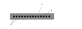
- the schematic sectional drawing which shows the belt main body of the conveyor belt of 1 aspect.
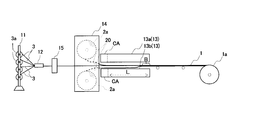
- the schematic block diagram which shows the equipment used for the manufacturing method of a conveyor belt.
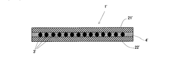
- the schematic sectional drawing which shows the belt main body of the conveyor belt of another aspect.
- the figure which shows the test method of steel cord drawing-out force.
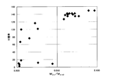
- the graph which shows the relationship between steel cord pulling force and metal zinc ratio.
- the graph which shows the relationship between a rubber adhesion rate and a metal zinc ratio.
- FIG. 1 is a cross-sectional view showing a cross-section of a conveyor belt.
- a conveyor belt according to this embodiment includes a cover rubber 2 in which a belt body 1 having a flat belt shape as a whole is made of a crosslinked rubber, and an inner side of the cover rubber 2. And a plurality of steel cords 3 embedded therein.
- the plurality of steel cords 3 are embedded in the center of the belt thickness direction so as to extend along the length direction of the conveyor belt 1, and are constant in the belt width direction as shown in FIG. They are buried in parallel with each other at a distance.
- the cover rubber 2 can be formed by a rubber composition conventionally used in a general conveyor belt.
- a rubber composition conventionally used in a general conveyor belt For example, natural rubber, BR (polybutadiene rubber), SBR (styrene-butadiene rubber), NBR (acrylonitrile-butadiene rubber), EPDM (ethylene-propylene-diene rubber), and a rubber composition based on a rubber mixture thereof are used.
- BR polybutadiene rubber
- SBR styrene-butadiene rubber
- NBR acrylonitrile-butadiene rubber
- EPDM ethylene-propylene-diene rubber
- the rubber composition for forming the cover rubber 2 may contain a reinforcing material, a crosslinking agent and the like as components other than the base rubber.
- a reinforcing material inorganic particles such as carbon black and silica, short fibers, and the like can be used.
- organic reinforcing agents such as phenol resins, high styrene resins, and coumarone indene resins may also be included in the rubber composition as components for reinforcing the cover rubber.
- an organic peroxide or sulfur can be employed as the crosslinking agent.
- a vulcanization accelerator such as a sulfenamide vulcanization accelerator and a thiazole vulcanization accelerator can be contained in the rubber composition together with such a crosslinking agent.
- rubber chemicals such as fillers such as talc and calcium carbonate, process oil, scorch inhibitor, peptizer, anti-aging agent and flame retardant are added to the rubber composition. Can be included.
- the steel cord 3 a conventional conveyor belt can be used as in the case of the cover rubber.
- the zinc-plated surface, the amount of zinc in the metal state on the zinc-plated surface is “M Zn ”, and the amount of zinc in the oxide state is “M ZnO ” It is important to use those in which these ratios (M Zn / M ZnO ) sometimes exceed 0.05.
- M Zn / M ZnO the ratio of the zinc of a metal state and the zinc of an oxide state in the surface of the steel cord by which this galvanization was carried out, it can obtain
- Zinc on the surface of the steel cord may exist in the metal state and in the hydroxide state and other salt states in addition to the oxide state. There is almost no zinc other than the state of zinc in the state, and zinc in other states is at most about 10% of the whole. Therefore, the state in which the ratio of zinc in the metal state to zinc in the oxide state (M Zn / M ZnO ) exceeds 0.05 generally means that the metal state zinc (M Zn) occupies the entire zinc on the surface of the steel cord. ) Is in a state exceeding 5%. And that the said ratio (henceforth "metal zinc ratio”) is high has shown that zinc exists in the metal state on the surface of a steel cord by that much. This zinc in a metallic state has a strong chemical bonding force with rubber.
- sulfur is used as a crosslinking agent contained in the rubber composition, or a vulcanization accelerator containing sulfur is added to the rubber composition.
- a strong chemical bond between zinc and sulfur is formed, and the cover rubber and the steel cord are firmly bonded.
- the above action cannot be expected with zinc in an oxide state.
- the metal zinc ratio exhibits a strong adhesive force with the cover rubber
- the metal zinc ratio is preferably 0.07 or more, It is especially preferable that it is 0.09 or more.
- the metal zinc ratio is preferably a higher value, but if a steel cord with a metal zinc ratio higher than necessary is used, only a specially treated steel cord may be used. Further, there is a possibility that the cost of the conveyor belt may be increased by requiring strict management for storage until the steel cord is obtained and buried in the cover rubber. Moreover, even if the metal zinc ratio is excessively improved, it is difficult to improve the adhesion between the cover rubber and the steel cord beyond a certain level.
- the upper limit is usually about 0.25, but the metal zinc ratio is excessively improved as described above. However, it is difficult to obtain more effects than just over-quality. Therefore, the metal zinc ratio is preferably 0.15 or less, and particularly preferably 0.1 or less.
- the steel cord may be, for example, a stranded wire formed by twisting a plurality of strands that have been subjected to hot dip galvanizing, or a single wire.
- the ratio should be the above value on the surface in contact with the rubber, and the surface condition as described above is obtained even for the strand that is not necessarily exposed to the surface because it is twisted inside the stranded wire. It is not a thing.
- the ratio of the metal zinc on the surface of the steel cord should be at least the above value in the manufacturing stage of the conveyor belt, and, in an extreme case, in the non-crosslinked rubber composition for forming the cover rubber. It is sufficient that the above value is obtained immediately before being buried. Therefore, it is not necessary to make the metal zinc ratio exceed 0.05 immediately after obtaining the steel cord, and as shown in the later stage, the steel cord is embedded in the non-crosslinked rubber composition in the manufacturing process of the conveyor belt. Prior to the adjustment, the metal zinc ratio may be adjusted to be in a state exceeding 0.05. For this reason, it is preferable to know the state of the surface of the steel cord in advance, and it is preferable to perform the step of measuring the amount of zinc in the metallic state of the surface of the steel cord before the embedding.
- FIG. 2 is a front view showing the schematic configuration of the conveyor belt manufacturing facility, and the direction from the left side to the right side in FIG. 2 is the flow direction of the manufacturing line.
- the manufacturing facility includes a bobbin rack 11 in which a plurality of bobbins 3 a around which the steel cord 3 is wound are set in a state where the steel cord 3 can be fed out. Is provided. Further, a plurality of bobbins 3a are also present in the depth direction in FIG. 2. On the downstream side of the bobbin rack 11 in the steel cord feeding direction, the steel cords 3 fed from the plurality of bobbins 3a are arranged in the depth direction in the figure. Alignment jigs 12 are provided for arranging them at substantially equal intervals.
- the conveyor belt manufacturing facility in the present embodiment is provided with a heat press machine 13, and the alignment jig 12 has two hot plates (upper part) facing each other in the hot press machine 13. Between the hot platen 13a and the lower hot platen 13b), it is provided at a position where the steel cord 3 can be held horizontally.
- the conveyor belt manufacturing facility in the present embodiment is provided with a rubber sea track 14 for supplying an uncrosslinked rubber sheet 20 for forming the cover rubber 2 to the hot press machine 13, Two sheet rolls 2a around which the uncrosslinked rubber sheet 20 is wound are set on the rubber sea track 14, and these sheet rolls 2a are spaced apart from each other in the horizontal direction with the central axis of rotation thereof in the horizontal direction.
- the rubber sea track 14 is set.
- the sheet roll 2a is set on the rubber sea track 14 so that the wound uncrosslinked rubber sheet 20 can be fed out in the same direction as the steel cord 3, and the upper sheet roll 2a is The uncrosslinked rubber sheet 20 is set between the upper hot platen 13a of the hot press machine 13 and the steel cord 3, and the lower sheet roll 2a is set at the lower hot platen 13b of the hot press machine 13. And the steel cord 3 are set so that the uncrosslinked rubber sheet 20 can be fed out.
- the heat press 13 moves between the two strip-shaped uncrosslinked rubber sheets 20 when the upper hot platen 13a and the lower hot platen 13b are moved so as to be close to each other.
- the conveyor belt manufacturing facility is provided so that the steel cord 3 can be hot-pressed, and the uncrosslinked rubber sheet 20 supplied from the sheet roll 2a is hot-pressed in order from the end, so-called “feed”. It is formed so that a long belt body can be produced by “baking”. In this feed firing, two hot presses are usually applied to a part of the area, but the advantage of using a galvanized steel cord is also demonstrated in this respect. Is.
- galvanized steel cords are not only easily corroded even when water infiltrates into the core body, but they also reduce the adhesion to rubber due to thermal aging. It has a merit that it is difficult, and is suitable as a core of a conveyor belt manufactured by feed baking.
- the upper heating platen 13a and the lower heating platen 13b cool the region close to the rubber sea track 14 side with cooling water so that heat is not applied to the uncrosslinked rubber sheet 20 during hot pressing. It is comprised so that it may be obtained, and it has the cooling area
- the belt main body 1 in which the steel cord 3 is embedded in the central portion in the thickness direction of the cover rubber 4 formed by crosslinking the uncrosslinked rubber sheet 20 can be manufactured by the length (L) by one hot press. It is configured as follows.
- a winding device 1 a for winding the belt main body 1 obtained by crosslinking the uncrosslinked rubber sheet 20 with the hot press machine 13 includes the hot press 13. It is further provided on the downstream side.
- the steel cord 3 is washed with weak alkaline electrolytic alkaline washing water, and only a very small part of the surface of the galvanized surface of the steel cord 3 is melted.
- a cleaning / drying device 15 for removing oxide zinc (zinc oxide) and drying the steel cord 3 after the cleaning includes a downstream side of the alignment jig 12 and an upstream side of the rubber sea track 14. It is prepared at the position.
- the manufacturing method of the conveyor belt which concerns on this embodiment using such a manufacturing facility can be implemented by the following processes, for example.
- a) The uncrosslinked rubber sheet 20 is prepared from the uncrosslinked rubber composition for forming the cover rubber, and the two sheet rolls 2a around which the uncrosslinked rubber sheet 20 is wound are set on the rubber sea track 14. Uncrosslinked rubber sheet preparation process.
- a bobbin 3a in which the amount of zinc in the metal state is measured is set on the bobbin rack 11, and the steel cord 3 is drawn out from the bobbin, and the alignment jig 12, the cleaning / drying device 15, and the heat press machine 13 is a wire passing process in which the tip 13 is passed through the winding device 1a.
- the uncrosslinked rubber sheet 20 is fed out from the respective sheet rolls 2a of the rubber sea track 14, and the leading end thereof is introduced into the hot press machine 13, and the uncrosslinked rubber sheet 20 is temporarily fixed to the steel cord 3. And a sheet setting step for producing a three-layered laminate of uncrosslinked rubber sheet 20 / steel cord 3 / uncrosslinked rubber sheet 20.
- the winding device 1a is operated, and the belt body 1 obtained in the hot press step (f) is moved downstream by the length of the hot platen excluding the cooling area CA, and pressed by the cooling area CA.
- a portion (“B" in FIG. 2) is left between the upper heating platen 13a and the lower heating platen 13b, and a new uncrosslinked rubber sheet 20 and steel are formed between the upper and lower heating plates (13a, 13b).
- Transfer process to pull in the code 3. h) The cleaning / drying device 15 is operated, and the steel cord 3 moved downstream through the cleaning / drying device 15 in the transfer step (g) is subjected to the cleaning condition setting step (e). A cleaning / drying process for performing cleaning under set conditions and drying the steel cord 3 after cleaning.
- the belt body 1 can be manufactured.
- the process which attaches attached equipments, such as a crosspiece, to the obtained belt main body 1 as needed, or is processed into an endless shape, and makes it a conveyor belt it is the same as the case of producing a general conveyor belt. Therefore, detailed description is omitted here.
- the unvulcanized rubber composition is kneaded using a general rubber kneading device such as a Banbury mixer, a kneader, or a three roll. Then, a method of forming the kneaded product into a sheet using a calender roll or the like can be employed.
- a general rubber kneading device such as a Banbury mixer, a kneader, or a three roll.
- the said surface analysis process (b) can be implemented according to the method as described in [Example] of a latter stage. Further, in the wiring step (c), the steel cord 3 is passed between the teeth of the alignment jig one by one using the comb-tooth alignment jig in the belt width direction. It is possible to employ a method in which a plurality of steel cords 3 are arranged so as to have a predetermined pitch and are passed between the hot plates of the hot press machine 13.
- the cleaning condition setting step (e) what is the state of oxide zinc on the surface of the steel cord plating, and what cleaning can be performed to achieve a desired metal zinc ratio?
- a method can be adopted in which a condition table is prepared in advance for each type of steel cord, and the operating conditions of the cleaning / drying device 15 are set according to the condition table.
- the cleaning / drying device 15 may be operated under the same conditions without performing the surface analysis step (b).
- the surface of the cord is oxidized, the metal zinc ratio of the steel cord after the washing / drying step (h) may not exceed 0.05.
- zinc will be dissolved more than necessary in the electrolytic alkaline cleaning water used for the cleaning, there is a possibility that the cleaning ability of the electrolytic alkaline cleaning water may be reduced at an early stage. Also from such a viewpoint, it is preferable that the surface analysis step (b) is performed to grasp the surface state of the steel cord in advance.
- the conveyor belt may cause cracks or chipping in the cover rubber depending on the conveyed product, and may cause water to enter from the outside into the part where the steel cord is embedded.
- the rubber composition By allowing the rubber composition to enter the steel cord, it is possible to prevent water from being transmitted in the belt length direction through the steel cord.
- the steel cord employs a twisted structure in which a plurality of strands in which a plurality of strands are twisted together are used, it is preferable to allow rubber to enter at least between the strands.
- the washing / drying step (h) is performed in order to improve the metal zinc ratio of the steel cord than before the contact by bringing the steel cord into contact with electrolytic alkaline washing water capable of removing zinc in an oxide state.
- metal zinc ratio improving process the process aiming to improve the ratio of zinc in the metallic state as in the washing / drying process is also referred to as “metal zinc ratio improving process”.
- the electrolytic alkaline washing water for removing zinc in the oxide state on the surface
- other alkaline liquids such as an aqueous sodium hydroxide solution or an aqueous calcium hydroxide solution can be used for the electrolysis.
- an acidic liquid such as dilute hydrochloric acid or dilute sulfuric acid may be used.
- the electrolytic alkaline cleaning water is water obtained on the cathode side when water containing a slight amount of electrolyte is electrolyzed, and usually exhibits an alkaline property of about pH 9 to 12, and is generally alkaline. Unlike aqueous solution, it contains almost no metal ions. From this, by using electrolytic alkaline cleaning water, unlike other alkaline liquids and acidic liquids as exemplified above, there is a low risk of problems caused by residual ions, and in adhesiveness to the cover rubber. High reliability can be obtained.
- the steel cord is again attached with ion-exchanged water.
- the steel cord may be dried after washing with (1).
- a method generally employed as a wire rod drying means such as an air knife can also be employed in the method of manufacturing a conveyor belt according to the present embodiment.
- the steel cord is preferably not completely dried, and is preferably in a state where a certain amount of moisture is adhered.
- the adhesion between the rubber composition and the steel cord is improved by attaching moisture to the surface of the steel cord because the hydrolysis reaction occurs in the components contained in the uncrosslinked rubber composition. This is probably because a functional group such as a hydroxyl group is formed, and a chemical bond is formed between the component and zinc on the plating surface via the hydroxyl group. In order to exert such an effect, it is conceivable that water is added to the rubber composition.
- the water added in the step of kneading the rubber composition or the step of sheeting the uncrosslinked rubber sheet is used. Since it becomes easy to dissipate, the said effect can be acquired more reliably by making it adhere to the surface of a steel cord. Further, the moisture may be adhered by making the steel cord after washing insufficiently dried, or may be adhered in a subsequent process after the steel cord is completely dried. In that case, methods such as brushing or spraying can be employed.
- the amount of adhesion is 0.01 to 1.0 when the mass of the steel cord is 100. It is preferable to be within the range.
- zinc in the metal state on the plating surface may be oxidized, which may reduce the metal zinc ratio. Therefore, it is preferable that the time for maintaining the state in which moisture is attached to the steel cord after the metal zinc ratio is improved and before being embedded in the uncrosslinked rubber composition by the hot press is as short as possible. More specifically, it is preferable to carry out the hot pressing within 8 hours after adhering moisture to the steel cord having an improved metal zinc ratio at the longest.
- the amount of moisture adhering is 0.01 to 0.5 when the mass of the steel cord is 100, in that even if the moisture adhering for a long time does not adversely affect the adhesion to the rubber composition. More preferably, it is particularly preferably 0.01 to 0.03.
- the hot pressing step is carried out following the washing / drying step (h) so that it can be prevented.
- the steel cord is previously brought into contact with electrolytic alkaline washing water and zinc in the oxide state is galvanized.
- the bobbin removed from the surface layer and wound with the steel cord may be set on the bobbin rack, and the washing / drying step (h) may not be performed after the hot pressing step (f) is started.
- the metal zinc ratio improving step for improving the ratio of zinc in the metal state more than before can be performed as follows.
- the metal zinc ratio improving process by plasma discharge is, for example, a reducing gas such as hydrogen or carbon monoxide, or a mixed gas in which a gas such as nitrogen or argon is mixed with the reducing gas. Then, a reducing atmosphere is formed, and a steel cord is placed in the reducing atmosphere, and the surface of the steel cord is irradiated with atmospheric pressure plasma.
- a gas blow type atmospheric pressure plasma generator is supplied with nitrogen gas slightly mixed with hydrogen gas as a discharge gas, and the plasma generated in the discharge gas is converted into a plasma together with the discharge gas.
- a method of blowing from a gas head to a steel cord can be employed. In this way, by reducing zinc in the oxide state on the surface of the steel cord to the metal state, the metal zinc ratio can be improved as compared with that before the plasma discharge.
- the metal zinc ratio improving process by laser irradiation is performed by, for example, forming a reducing atmosphere with a reducing gas and a mixed gas in which a gas such as nitrogen or argon and the reducing gas are mixed. This can be carried out by placing a steel cord in the reducing atmosphere and heating the surface of the steel cord with laser light.
- the irradiation laser may be a solid laser such as a YAG laser or a gas laser such as a carbon dioxide laser, and the oscillation method is not particularly limited, such as a pulse laser or a CW laser. .
- the surface can be strongly heated in a short time, not only can the zinc in the oxide state existing on the surface of the steel cord be reduced to the metal state, but also the zinc plating on the surface of the steel cord. Can be melted by heat to break the surface oxide film of the galvanizing and expose the metallic zinc inside. Therefore, the ratio of zinc in the metal state on the surface of the steel cord can be further increased as compared to before the metal zinc ratio improving step. Moreover, the surface can be appropriately roughened by hot-melting and solidifying galvanizing, the contact area with rubber can be increased, and the anchor effect can be increased. Therefore, by adopting a laser irradiation method as the metal zinc ratio improving step, it is possible to expect a more excellent effect in the adhesiveness to rubber.
- the metal zinc ratio improving step is carried out by washing with electrolytic alkaline washing water or the like, even if the steel cord is a stranded wire, the surface of each strand can be subjected to a substantially uniform treatment.
- the effect of increasing the surface zinc metal ratio compared to before can be exhibited substantially uniformly across the entire surface of the strands and between the strands. Therefore, as described above, when the hot pressing is performed under the condition that the rubber composition enters between the strands of the steel cord, the adhesiveness with the rubber is good not only on the outer surface of the steel cord but also on the inside. Will be demonstrated.
- the metal zinc ratio improvement process can also be implemented by a method other than the above examples, and the method may be appropriately selected depending on the required characteristics of the conveyor belt to be manufactured, the line speed of the production line, and the like.
- the belt body in which the steel cord is embedded in the cover rubber itself is illustrated, but, for example, as shown in FIG.
- the case where the adhesive rubber 4 ′ is provided between the back cover rubber 22 and the belt body 1 ′ in which the steel cord 3 ′ is embedded in the adhesive rubber 4 ′ is formed is also within the intended scope of the present invention.
- the ratio of metal zinc (M Zn / M ZnO ) on the galvanized surface exceeds 0.05.
- M Zn / M ZnO metal zinc
- test piece for steel cord pull-out test A test piece for a steel cord pull-out test having the shape shown in FIG. 4 was produced from the sample for evaluation according to the method described in JIS K 6369. In addition, the length (l 2 ) of the drawing portion is 100 ⁇ 2 mm.
- Step cord pull-out test Measurement of “pull-out force” of steel cord
- the steel cord pull-out test specimen prepared is placed in a standard room of 23 ⁇ 2 ° C. for 3 hours or longer, the specimen is correctly attached to the gripping tool at a distance of 250 mm or more between the gripping tools and pulled.
- the steel sheet was pulled at a speed of 100 ⁇ 10 mm / min, and the maximum tensile force observed until the steel cord was pulled out was measured to evaluate the adhesive strength between the steel cord and rubber.
- the rubber adhesion rate was obtained by visually observing the surface of the steel cord after measuring the steel cord drawing force, and calculating the ratio of the area where the rubber adhered to the surface with respect to the total surface area of the steel cord in the drawn portion.
- the surface of the steel cord was measured by an X-ray photoelectron spectroscopy (XPS), and zinc in the metal state and zinc in the oxide state were respectively quantified. Specifically, the steel cord was cut into 2 cm, fixed to the platen, and the surface of the wire constituting the outermost side of the steel cord was measured under the following conditions.
- XPS X-ray photoelectron spectroscopy
- XPS device Model name “Quantum-2000” manufactured by ULVAC-PHI X-ray source: Al-K ⁇ X-ray beam diameter: 100 ⁇ m
- Neutralization conditions electron + argon photoelectron extraction angle: 45 degrees
- Sputtering conditions Argon ions @ 2 keV (2 mm ⁇ 2 mm) (1.5 nm / min in terms of SiO 2 )
- the steel cord was sputtered to a depth of 1 nm in order to eliminate the influence of surface contaminants, and the above analysis was performed using the surface after the sputtering as the surface of the steel cord.
- the raw data output from “Quantum-2000” is separated into waveforms using the “Fit” menu of Multipack (peak analysis software) manufactured by ULVAC-PHI. Baseline setting was performed, and each was quantified from the area ratio of the peak indicating zinc in the metal state and the peak indicating zinc in the oxide state.
- Sample No. Nos. 1 to 16 are prepared by performing various treatments on five types of steel cords having different production lots to adjust the amount of zinc in the metal state (M Zn ) and the amount of zinc in the oxide state (M ZnO ). .
- M Zn zinc in the metal state
- M ZnO zinc in the oxide state
- Each of 15 to 16 is of the same lot. 2 is No.2.
- the steel cord of the same lot as in No. 1 was acid-washed so that the metal zinc ratio exceeded 0.05.
- 3 is No.3.
- the steel cord of the same lot as 1 was washed with electrolytic alkaline washing water so that the metal zinc ratio exceeded 0.05.
- no. No. 4 is No.4. No.
- 1 is a steel cord of the same lot that has been subjected to wet heat aging. 5 is No.5. The steel cord of the same lot as 1 was washed with toluene. The other samples also adjust the metal zinc ratio on the surface by the same type of adjustment.
- Table 3 shows the results of the adhesion rate of rubber around the steel cord in the order of the metal zinc ratio.
- Plasma discharge conditions and laser irradiation conditions are as follows.
- Plasma discharge Using an atmospheric pressure plasma treatment system (remote type) manufactured by Air Water, select a preferred power supply frequency between 10 and 100 kHz to generate plasma, and move 3 mm from the plasma power supply to 0.75 m / min The steel cord was passed 10 times at speed. The plasma discharge was carried out while flowing hydrogen gas at a flow rate of 1 liter / min in nitrogen as blow gas.
- an atmospheric pressure plasma treatment system remote type manufactured by Air Water
- Sample No. 18 is Sample No. No. 17 was subjected to plasma discharge under the above conditions on the same lot of steel cord. Nos. 19 and 20 are obtained by performing laser irradiation under the above conditions 1 and 2, respectively.
- Sample No. Sample No. 22 No. 21 is a steel cord of the same lot subjected to wet heat aging. Nos. 23 to 25 are Nos. The 22 steel cords were subjected to plasma discharge and laser irradiation.
- the graph which put together the relationship between the value of the obtained drawing force and the adhesion rate, and the metal zinc ratio is shown in FIGS. Also from this figure, the ratio (M Zn / M ZnO ) between the amount of zinc in the metal state (M Zn ) and the amount of zinc in the oxide state (M ZnO ) on the galvanized surface is 0.05 or less. In this case, there are variations in the pulling force and the adhesion rate, and the ratio is generally low for steel cords exceeding 0.05.
- Steel code A Steel cord B (STC-B) having a diameter of 5 mm, in which 7 strands of 7 strands are twisted together: Steel cord steel cord C (STC-C) with a diameter of 6 mm in which seven strands of 19 strands are twisted together: Steel cord with a diameter of 8.5mm in which seven strands of 19 strands of strands differing from STC-B in strand configuration are twisted
- Each steel cord was taken out as it was and after degreasing with an organic solvent, after being immersed in water, taken out and held in the air for about 3 minutes until water did not drip from the steel cord, and the steel cord was dried.
- Drying condition 1 The steel cord subjected to the above drying was sprayed with compressed air of 4.8 kgf / cm 2 with a commercially available plug nozzle (trade name “Air Duster TD-30” manufactured by Trusco) and further dried (drying condition 2).
- the adhesion amount of moisture was calculated from the difference between the mass of the steel cord after these drying conditions and the mass of the steel cord before being immersed in water. Table 5 below shows the mass after drying (mass after drying) when the mass (initial mass) of the steel cord before immersion in water is 100.
- the adhesion amount of the water is in the range of 0.01 to 0.3, so that the adhesiveness is deteriorated even if left for a long time with the moisture attached. I find it difficult to see.
Landscapes
- Engineering & Computer Science (AREA)
- Mechanical Engineering (AREA)
- Ropes Or Cables (AREA)
- Belt Conveyors (AREA)
Abstract
本発明は、架橋ゴムによってベルト本体が形成されており、亜鉛メッキされたスチールコード(3)が心体としてベルト本体中に埋設されているコンベヤベルト(1)を製造すべく、ベルト本体を形成させるための未架橋ゴム組成物(20)中にスチールコード(3)を埋設させて未架橋ゴム組成物(20)を架橋するコンベヤベルトの製造方法であって、埋設させるスチールコード(3)として、亜鉛メッキがされている表面における金属状態の亜鉛の量(MZn)と酸化物状態の亜鉛の量(MZnO)との割合(MZn/MZnO)が0.05を超えるスチールコードを用いるコンベヤベルト(1)の製造方法に関するものであり、本発明は、これにより、ベルト本体を形成している架橋ゴムにスチールコード(3)が高い接着力で接着されているコンベヤベルト(1)を提供することが可能となる。
Description
本発明は、架橋ゴムによってベルト本体が形成されており、亜鉛メッキされたスチールコードが心体として前記ベルト本体中に埋設されているコンベヤベルトを製造するためのコンベヤベルトの製造方法、及び、コンベヤベルトに関する。
従来、コンベヤベルトとしては、長尺帯状のベルト本体のみからなるものや、このベルト本体に横桟や耳桟などの部材を取り付けられたものなどが知られている。
このコンベヤベルトとしては、前記ベルト本体を架橋ゴムで形成させたものが広く用いられている。
このコンベヤベルトとしては、例えば、前記ベルト本体の表裏において露出する部分をカバーゴムと呼ばれる架橋ゴムで形成させ、内部に帆布やスチールコードなどの心体を埋設させた構成を有するものが広く用いられている。
このコンベヤベルトとしては、前記ベルト本体を架橋ゴムで形成させたものが広く用いられている。
このコンベヤベルトとしては、例えば、前記ベルト本体の表裏において露出する部分をカバーゴムと呼ばれる架橋ゴムで形成させ、内部に帆布やスチールコードなどの心体を埋設させた構成を有するものが広く用いられている。
前記スチールコードは、表裏のカバーゴムの間に接着ゴムが設けられる場合には、この接着ゴム中に埋設されたりしている。
また、前記スチールコードは、接着ゴムが設けられておらず、ベルト本体が単一のカバーゴムで形成されるような場合には、該カバーゴム中に直接埋設されたりしている。
コンベヤベルトは、カバーゴムや接着ゴムといったベルト本体を形成している架橋ゴムと前記スチールコードとの接着状態によってベルト本体の強度や耐用期間(寿命)などが大きく左右されることから前記スチールコードと架橋ゴムとを優れた接着力で接着させることが求められている。
また、前記スチールコードは、接着ゴムが設けられておらず、ベルト本体が単一のカバーゴムで形成されるような場合には、該カバーゴム中に直接埋設されたりしている。
コンベヤベルトは、カバーゴムや接着ゴムといったベルト本体を形成している架橋ゴムと前記スチールコードとの接着状態によってベルト本体の強度や耐用期間(寿命)などが大きく左右されることから前記スチールコードと架橋ゴムとを優れた接着力で接着させることが求められている。
このスチールコードと架橋ゴムとの接着性の改善に関しては、下記特許文献1にも示されているように、スチールコードに接着させるゴム組成物の配合検討によるアプローチがこれまでの主流となっている。
しかし、コンベヤベルトのベルト本体を形成させるためのゴム組成物については、スチールコードとの接着性以外に求められる様々な要求特性をも満足させなければならないことからその他の要求特性を優先させる結果スチールコードとの接着性をある程度犠牲にしなければならない場合がある。
即ち、ゴム組成物の配合検討によるアプローチには制約が多くスチールコードと架橋ゴムとの接着性を十分に改善することは難しい。
しかし、コンベヤベルトのベルト本体を形成させるためのゴム組成物については、スチールコードとの接着性以外に求められる様々な要求特性をも満足させなければならないことからその他の要求特性を優先させる結果スチールコードとの接着性をある程度犠牲にしなければならない場合がある。
即ち、ゴム組成物の配合検討によるアプローチには制約が多くスチールコードと架橋ゴムとの接着性を十分に改善することは難しい。
一方でスチールコードは、ゴム組成物程多くの制約を受けることがないもののスチールコードによる接着性の改善については殆ど検討がなされておらず、その表面に亜鉛や真鍮などでメッキを施す程度のことしか検討されていない。
コンベヤベルトは、瓦礫や鉱石といった角張った重量物がベルト本体上に落下されるような重負荷条件下において使用されることが多いため、使用中にカバーゴムが破れてスチールコードを露出させることがある。
また、コンベヤベルトは、表面からスチールコードにまで至るクラックが使用中に形成されることがある。
このように、コンベヤベルトはスチールコードに外部から雨水などが伝わったりするような状況下で使用されることがあるために、用いるスチールコードとしては、同じメッキ厚みでも真鍮メッキ品よりも耐水性が良好な亜鉛メッキ品に対する要望が強い。
一方で亜鉛メッキされたスチールコードは、これまでに架橋ゴムとの接着性について殆ど検討がなされておらず、一般には、単に購入品をそのまま利用することしかなされていない。
このようなことからも、従来のコンベヤベルトにおいては、スチールコードと架橋ゴムとの接着性の改善についての要望を満足させることが困難な状況になっている。
コンベヤベルトは、瓦礫や鉱石といった角張った重量物がベルト本体上に落下されるような重負荷条件下において使用されることが多いため、使用中にカバーゴムが破れてスチールコードを露出させることがある。
また、コンベヤベルトは、表面からスチールコードにまで至るクラックが使用中に形成されることがある。
このように、コンベヤベルトはスチールコードに外部から雨水などが伝わったりするような状況下で使用されることがあるために、用いるスチールコードとしては、同じメッキ厚みでも真鍮メッキ品よりも耐水性が良好な亜鉛メッキ品に対する要望が強い。
一方で亜鉛メッキされたスチールコードは、これまでに架橋ゴムとの接着性について殆ど検討がなされておらず、一般には、単に購入品をそのまま利用することしかなされていない。
このようなことからも、従来のコンベヤベルトにおいては、スチールコードと架橋ゴムとの接着性の改善についての要望を満足させることが困難な状況になっている。
本発明は、上記のような問題を解決することを課題としており、ベルト本体を形成している架橋ゴムにスチールコードが高い接着力で接着されているコンベヤベルトを提供することを課題としている。
本発明者は、亜鉛メッキされたスチールコードに着目して上記課題の解決手段を鋭意検討した結果、所定の表面状態を有するスチールコードと未架橋ゴム組成物とを接触させて前記未架橋ゴム組成物の架橋を行うことで、該未架橋ゴム組成物を架橋させてなる架橋ゴムとスチールコードとの間に優れた接着性が発揮されることを見出して本発明を完成させるに至ったものである。
すなわち、コンベヤベルトの製造方法に係る本発明は架橋ゴムによってベルト本体が形成されており、亜鉛メッキされたスチールコードが心体として前記ベルト本体中に埋設されているコンベヤベルトを製造すべく、前記ベルト本体を形成させるための未架橋ゴム組成物中に前記スチールコードを埋設させて前記未架橋ゴム組成物を架橋するコンベヤベルトの製造方法であって、埋設させる前記スチールコードとして、前記亜鉛メッキがされている表面における金属状態の亜鉛の量(MZn)と酸化物状態の亜鉛の量(MZnO)との割合(MZn/MZnO)が0.05を超えるスチールコードを用いることを特徴としている。
また、コンベヤベルトに係る本発明は、上記のような製造方法によって形成されたことを特徴としている。
本発明によれば、所定の表面状態を有するスチールコードがベルト本体を形成させるための未架橋ゴム組成物中に埋設されて該ゴム組成物が架橋される。
従って、前記未架橋ゴム組成物を架橋させてなる架橋ゴムとスチールコードとの間に優れた接着性が発揮され得る。
従って、前記未架橋ゴム組成物を架橋させてなる架橋ゴムとスチールコードとの間に優れた接着性が発揮され得る。
以下に、本発明の好ましい実施の形態について、添付図面に基づき説明する。
まず、本実施形態に係る製造方法によって製造するコンベヤベルトについて説明する。
まず、本実施形態に係る製造方法によって製造するコンベヤベルトについて説明する。
図1は、コンベヤベルトの横断断面を示す断面図であり、本実施形態におけるコンベヤベルトは、全体が平ベルト形状を有するベルト本体1が架橋ゴムからなるカバーゴム2と、該カバーゴム2の内側に埋設された複数本のスチールコード3とによって構成されている。
前記複数本のスチールコード3は、コンベヤベルト1の長さ方向に沿って延在するようにベルト厚み方向中央部に埋設されており、図1にも記載されているようにベルト幅方向において一定距離を隔て、互いに並行する状態となって埋設されている。
前記カバーゴム2は、一般的なコンベヤベルトにおいて従来利用されているゴム組成物によって形成させることができる。
例えば、天然ゴム、BR(ポリブタジエンゴム)、SBR(スチレン-ブタジエンゴム)、NBR(アクリロニトリル-ブタジエンゴム)、EPDM(エチレン-プロピレン-ジエンゴム)及びこれらの混合ゴムをベースゴムとしたゴム組成物によって形成させることができる。
例えば、天然ゴム、BR(ポリブタジエンゴム)、SBR(スチレン-ブタジエンゴム)、NBR(アクリロニトリル-ブタジエンゴム)、EPDM(エチレン-プロピレン-ジエンゴム)及びこれらの混合ゴムをベースゴムとしたゴム組成物によって形成させることができる。
また、カバーゴム2を形成させるためのゴム組成物には、補強材、架橋剤などを前記ベースゴム以外の成分として含有させ得る。
前記補強材としては、カーボンブラックやシリカなどの無機粒子や短繊維などを採用することができる。
また、これらの補強材とともにフェノール樹脂、ハイスチレン樹脂、クマロンインデン樹脂などの有機補強剤もカバーゴムを補強するための成分として前記ゴム組成物に含有させ得る。
前記補強材としては、カーボンブラックやシリカなどの無機粒子や短繊維などを採用することができる。
また、これらの補強材とともにフェノール樹脂、ハイスチレン樹脂、クマロンインデン樹脂などの有機補強剤もカバーゴムを補強するための成分として前記ゴム組成物に含有させ得る。
また、前記架橋剤としては、有機過酸化物や硫黄を採用することができる。
なお、このような架橋剤とともにスルフェンアミド系加硫促進剤やチアゾール系加硫促進剤などの加硫促進剤を前記ゴム組成物に含有させ得る。
なお、このような架橋剤とともにスルフェンアミド系加硫促進剤やチアゾール系加硫促進剤などの加硫促進剤を前記ゴム組成物に含有させ得る。
さらに、このような成分以外にも、タルクや炭酸カルシウムなどの充填材、プロセスオイル、スコーチ防止剤、素練促進剤、老化防止剤、難燃剤などの一般的なゴム薬品を前記ゴム組成物に含有させ得る。
一方で、前記スチールコード3についても、カバーゴムと同様に一般的なコンベヤベルトにおいて従来利用されているものを採用することができる。
ただし、亜鉛メッキが施されているもので、且つ、この亜鉛メッキがされている表面における金属状態の亜鉛の量を「MZn」とし、酸化物状態の亜鉛の量を「MZnO」としたときのこれらの割合(MZn/MZnO)が0.05を超える状態のものを用いることが重要である。
この亜鉛メッキがされたスチールコードの表面における金属状態の亜鉛と酸化物状態の亜鉛との割合については、実施例記載の方法によって求めることができる。
なお、以下において、単に「スチールコード」との用語を用いる場合には、特段のことわりがない限りにおいて「亜鉛メッキがされたスチールコード」を意図している。
ただし、亜鉛メッキが施されているもので、且つ、この亜鉛メッキがされている表面における金属状態の亜鉛の量を「MZn」とし、酸化物状態の亜鉛の量を「MZnO」としたときのこれらの割合(MZn/MZnO)が0.05を超える状態のものを用いることが重要である。
この亜鉛メッキがされたスチールコードの表面における金属状態の亜鉛と酸化物状態の亜鉛との割合については、実施例記載の方法によって求めることができる。
なお、以下において、単に「スチールコード」との用語を用いる場合には、特段のことわりがない限りにおいて「亜鉛メッキがされたスチールコード」を意図している。
前記スチールコードの表面の亜鉛は、前記金属状態、並びに、前記酸化物状態以外に、水酸化物状態や、その他の塩の状態となって存在しうるが、通常、金属状態の亜鉛と酸化物状態の亜鉛の状態以外の亜鉛は殆ど存在せず、その他の状態の亜鉛は、多くとも、全体の10%程度である。
したがって、金属状態の亜鉛と酸化物状態の亜鉛との割合(MZn/MZnO)が0.05を超える状態とは、概ね、スチールコードの表面の亜鉛全体に占める金属状態の亜鉛(MZn)の割合が5%を超える状態となっていることに等しい。
そして、前記割合(以下、「金属亜鉛比率」ともいう)が高いということは、それだけ、スチールコードの表面に亜鉛が金属状態で存在することを示している。
この金属状態の亜鉛はゴムとの化学的な結合力が強く、特に、前記ゴム組成物に含有させる架橋剤として硫黄を採用したり、硫黄を含んだ加硫促進剤などを前記ゴム組成物に含有させると、亜鉛と硫黄との強固な化学的結合が形成され、カバーゴムとスチールコードとが強固に接着されることになる。
一方で、酸化物状態の亜鉛では上記のような作用が期待できない。
したがって、金属状態の亜鉛と酸化物状態の亜鉛との割合(MZn/MZnO)が0.05を超える状態とは、概ね、スチールコードの表面の亜鉛全体に占める金属状態の亜鉛(MZn)の割合が5%を超える状態となっていることに等しい。
そして、前記割合(以下、「金属亜鉛比率」ともいう)が高いということは、それだけ、スチールコードの表面に亜鉛が金属状態で存在することを示している。
この金属状態の亜鉛はゴムとの化学的な結合力が強く、特に、前記ゴム組成物に含有させる架橋剤として硫黄を採用したり、硫黄を含んだ加硫促進剤などを前記ゴム組成物に含有させると、亜鉛と硫黄との強固な化学的結合が形成され、カバーゴムとスチールコードとが強固に接着されることになる。
一方で、酸化物状態の亜鉛では上記のような作用が期待できない。
このようなことから、金属亜鉛比率の高い方がカバーゴムとの間に強固な接着力が発揮されることを期待することができ前記金属亜鉛比率は、0.07以上であることが好ましく、0.09以上であることが特に好ましい。
なお、この金属亜鉛比率は、より高い値であることが好ましいものではあるが、必要以上に金属亜鉛比率の高いスチールコードを用いようとすると、特別な処理を施したスチールコードしか使用できなくなったり、該スチールコードを入手後のカバーゴム中に埋設するまでの保管に厳重な管理を要したりしてコンベヤベルトのコストアップを招くおそれを有する。
また、過度に前記金属亜鉛比率を向上させても、カバーゴムとスチールコードとの接着性を一定以上に向上させることは困難である。
なお、後述するような金属亜鉛比率を向上させるための処理をいかに施したとしても、その上限値は、通常、0.25程度となるが、上記のように過度に金属亜鉛比率を向上させても過剰品質になるばかりでそれ以上の効果を得ることが難しい。
このようなことから、金属亜鉛比率は、0.15以下とされることが好ましく、0.1以下とされることが特に好ましい。
なお、この金属亜鉛比率は、より高い値であることが好ましいものではあるが、必要以上に金属亜鉛比率の高いスチールコードを用いようとすると、特別な処理を施したスチールコードしか使用できなくなったり、該スチールコードを入手後のカバーゴム中に埋設するまでの保管に厳重な管理を要したりしてコンベヤベルトのコストアップを招くおそれを有する。
また、過度に前記金属亜鉛比率を向上させても、カバーゴムとスチールコードとの接着性を一定以上に向上させることは困難である。
なお、後述するような金属亜鉛比率を向上させるための処理をいかに施したとしても、その上限値は、通常、0.25程度となるが、上記のように過度に金属亜鉛比率を向上させても過剰品質になるばかりでそれ以上の効果を得ることが難しい。
このようなことから、金属亜鉛比率は、0.15以下とされることが好ましく、0.1以下とされることが特に好ましい。
なお、スチールコードは、例えば、溶融亜鉛メッキが施された素線が複数本撚り掛けられてなる撚り線であっても、単線であってもよく、撚り線である場合には、上記金属亜鉛比率は、ゴムと接する表面において上記のような値となっていれば良く、必ずしも撚り線の内側に撚り込まれており表面に露出することのない素線にまで上記のような表面状態を求めるものではない。
また、スチールコードの表面における前記金属亜鉛比率は、少なくとも、コンベヤベルトの製造段階において上記の値となっていれば良く、極端に言えば、前記カバーゴムを形成させるための非架橋ゴム組成物に埋設される直前において上記の値となっていれば良い。
従って、スチールコードの入手後すぐに金属亜鉛比率を0.05を超える状態にする必要はなく、後段においてに示すように、コンベヤベルトの製造工程においてスチールコードを非架橋ゴム組成物に埋設するのに先立って金属亜鉛比率が0.05を超える状態となるように調整すればよい。
このようなことから、当該スチールコードの表面の状態を事前に把握しておくことが好ましく、スチールコードの表面の金属状態の亜鉛の量を測定する工程を前記埋設前において実施することが好ましい。
従って、スチールコードの入手後すぐに金属亜鉛比率を0.05を超える状態にする必要はなく、後段においてに示すように、コンベヤベルトの製造工程においてスチールコードを非架橋ゴム組成物に埋設するのに先立って金属亜鉛比率が0.05を超える状態となるように調整すればよい。
このようなことから、当該スチールコードの表面の状態を事前に把握しておくことが好ましく、スチールコードの表面の金属状態の亜鉛の量を測定する工程を前記埋設前において実施することが好ましい。
以下に、このような工程を採用したコンベヤベルトの製造方法について説明する。
まず、図2を参照しつつ、コンベヤベルトの製造設備について説明する。
まず、図2を参照しつつ、コンベヤベルトの製造設備について説明する。
図2はコンベヤベルトの製造設備の概略構成を示す正面図であり、図2正面視左側から右側に向けた方向が製造ラインの流れ方向となっている。
この図2にも示されているように、この製造設備には、前記スチールコード3が巻き取られた複数のボビン3aが、前記スチールコード3を繰り出し可能な状態でセットされたボビンラック11が備えられている。
また、前記ボビン3aは図2における奥行き方向にも複数存在しており、前記ボビンラック11のスチールコード繰り出し方向下流側には、これら複数のボビン3aから繰り出されるスチールコード3を図の奥行き方向に略等間隔で並べて配置するための整列治具12が備えられている。
この図2にも示されているように、この製造設備には、前記スチールコード3が巻き取られた複数のボビン3aが、前記スチールコード3を繰り出し可能な状態でセットされたボビンラック11が備えられている。
また、前記ボビン3aは図2における奥行き方向にも複数存在しており、前記ボビンラック11のスチールコード繰り出し方向下流側には、これら複数のボビン3aから繰り出されるスチールコード3を図の奥行き方向に略等間隔で並べて配置するための整列治具12が備えられている。
また、本実施形態におけるコンベヤベルトの製造設備には、熱プレス機13が備えられており、前記整列治具12は、前記熱プレス機13において上下に対向している2枚の熱盤(上部熱盤13aと下部熱盤13b)の間においてスチールコード3を水平に保持し得る位置に備えられている。
さらに、本実施形態におけるコンベヤベルトの製造設備には、前記カバーゴム2を形成させるための未架橋ゴムシート20を前記熱プレス機13に供給するためのゴムシートラック14が備えられており、該ゴムシートラック14には、前記未架橋ゴムシート20が巻き取られたシートロール2aが2個セットされており、これらのシートロール2aはその回転中心軸を水平方向に向けて上下に離間した状態で前記ゴムシートラック14にセットされている。
また、前記シートロール2aは巻き取られた未架橋ゴムシート20を前記スチールコード3の繰り出し方向と同方向に繰り出し得るように前記ゴムシートラック14にセットされており、上部側のシートロール2aは前記熱プレス機13の上部熱盤13aとスチールコード3との間に未架橋ゴムシート20を繰り出し得るようにセットされており、下部側のシートロール2aは前記熱プレス機13の下部熱盤13bとスチールコード3との間に未架橋ゴムシート20を繰り出し得るようにセットされている。
また、前記シートロール2aは巻き取られた未架橋ゴムシート20を前記スチールコード3の繰り出し方向と同方向に繰り出し得るように前記ゴムシートラック14にセットされており、上部側のシートロール2aは前記熱プレス機13の上部熱盤13aとスチールコード3との間に未架橋ゴムシート20を繰り出し得るようにセットされており、下部側のシートロール2aは前記熱プレス機13の下部熱盤13bとスチールコード3との間に未架橋ゴムシート20を繰り出し得るようにセットされている。
すなわち、前記熱プレス機13は、上部熱盤13aと下部熱盤13bとを接近させるように移動させてこれらを閉じた状態にさせた場合に2枚の帯状の未架橋ゴムシート20の間に前記スチールコード3を挟んで熱プレスし得るように当該コンベヤベルトの製造設備に備えられており、前記シートロール2aから供給される未架橋ゴムシート20を端から順に熱プレスして、いわゆる“送り焼き”によって長尺のベルト本体を作製し得るように形成されている。
なお、この送り焼きに際しては、通常、一部の領域に対して2度の熱プレスが加えられることになるが、亜鉛メッキされたスチールコードを利用するメリットは、このような点においても発揮されるものである。
すなわち、真鍮メッキされたスチールコードに比べて亜鉛メッキされたスチールコードは仮に水が心体部分に浸入した場合であっても腐食され難いばかりでなく、熱老化によってゴムとの接着力を低下させ難いというメリットを有しており、送り焼きによって製造されるコンベヤベルトの心体として好適なものである。
なお、この送り焼きに際しては、通常、一部の領域に対して2度の熱プレスが加えられることになるが、亜鉛メッキされたスチールコードを利用するメリットは、このような点においても発揮されるものである。
すなわち、真鍮メッキされたスチールコードに比べて亜鉛メッキされたスチールコードは仮に水が心体部分に浸入した場合であっても腐食され難いばかりでなく、熱老化によってゴムとの接着力を低下させ難いというメリットを有しており、送り焼きによって製造されるコンベヤベルトの心体として好適なものである。
なお、この上部熱盤13aと下部熱盤13bとは、前記ゴムシートラック14の側に近い領域を冷却水で冷却して熱プレス時において前記未架橋ゴムシート20に熱が加わらない状態にさせ得るように構成されており、前記冷却水の循環される冷却領域CAを備えている。
このことによって熱プレス機13の熱が、当該熱プレス機13の手前で待機している未架橋ゴムシート20に伝達して熱プレス前の未架橋ゴムシート20の架橋が進行するのを防止し得るようになっている。
従って、本実施形態におけるコンベヤベルトの製造設備は、1回の熱プレスによってこの冷却領域CAを除く熱盤の長さ(L)分だけ帯状の未架橋ゴムシート20を架橋し得るように構成されており、未架橋ゴムシート20が架橋されてなるカバーゴム4の厚み方向中央部にスチールコード3を埋設させたベルト本体1を1回の熱プレスで前記長さ(L)分だけ製造し得るように構成されている。
このことによって熱プレス機13の熱が、当該熱プレス機13の手前で待機している未架橋ゴムシート20に伝達して熱プレス前の未架橋ゴムシート20の架橋が進行するのを防止し得るようになっている。
従って、本実施形態におけるコンベヤベルトの製造設備は、1回の熱プレスによってこの冷却領域CAを除く熱盤の長さ(L)分だけ帯状の未架橋ゴムシート20を架橋し得るように構成されており、未架橋ゴムシート20が架橋されてなるカバーゴム4の厚み方向中央部にスチールコード3を埋設させたベルト本体1を1回の熱プレスで前記長さ(L)分だけ製造し得るように構成されている。
また、本実施形態におけるコンベヤベルトの製造設備には、前記熱プレス機13で未架橋ゴムシート20が架橋されて得られたベルト本体1を巻き取るための巻取り装置1aが前記熱プレス13の下流側にさらに備えられている。
さらに、本実施形態におけるコンベヤベルトの製造設備には、弱アルカリ性の電解アルカリ洗浄水によってスチールコード3を洗浄し、該スチールコード3の亜鉛メッキの表層の極一部のみを溶解することによって表面の酸化物状態の亜鉛(酸化亜鉛)を除去するとともに前記洗浄後にスチールコード3を乾燥させるための洗浄・乾燥装置15が前記整列治具12の下流側、且つ、前記ゴムシートラック14の上流側となる位置に備えられている。
さらに、本実施形態におけるコンベヤベルトの製造設備には、弱アルカリ性の電解アルカリ洗浄水によってスチールコード3を洗浄し、該スチールコード3の亜鉛メッキの表層の極一部のみを溶解することによって表面の酸化物状態の亜鉛(酸化亜鉛)を除去するとともに前記洗浄後にスチールコード3を乾燥させるための洗浄・乾燥装置15が前記整列治具12の下流側、且つ、前記ゴムシートラック14の上流側となる位置に備えられている。
このような製造設備を利用して、本実施形態に係るコンベヤベルトの製造方法は、例えば、以下のような工程によって実施することができる。
a)前記カバーゴムを形成させるための未架橋ゴム組成物によって前記未架橋ゴムシート20を作製し、該未架橋ゴムシート20を巻き取った2つのシートロール2aを前記ゴムシートラック14にセットする未架橋ゴムシート準備工程。
b)前記ボビンラック11にセットする各ボビン3aに対して、巻き取られているスチールコード3の表面の金属状態の亜鉛の量を測定し、金属亜鉛比率を求める表面分析工程。
c)金属状態の亜鉛量が測定されたボビン3aを前記ボビンラック11にセットし、該ボビンからスチールコード3を繰り出して、前記整列治具12、前記洗浄・乾燥装置15、及び、熱プレス機13を通過させてその先端部を前記巻取り装置1aにセットする通線工程。
d)前記ゴムシートラック14のそれぞれのシートロール2aから未架橋ゴムシート20を繰り出し、その先端部を前記熱プレス機13に導入し、それぞれの未架橋ゴムシート20をスチールコード3に仮り止めして、未架橋ゴムシート20/スチールコード3/未架橋ゴムシート20の3段重ねの積層体を作製するシートセット工程。
e)前記表面分析工程(b)での測定結果に基づき、洗浄・乾燥装置15によるスチールコード3の洗浄条件を設定する洗浄条件設定工程。
f)熱プレス機13を動作させ、前記シートセット工程(d)で作製した積層体を架橋一体化させてベルト本体1を形成させる熱プレス工程。
g)前記巻取り装置1aを動作させ、前記熱プレス工程(f)で得られたベルト本体1を冷却領域CAを除く熱盤の長さ分だけ下流側に移動させ、冷却領域CAによってプレスした部分(図2“B”)が上部熱盤13aと下部熱盤13bとの間に残った状態にさせるとともにこの上部・下部熱盤(13a,13b)間に新たな未架橋ゴムシート20とスチールコード3とを引き入れる移送工程。
h)前記洗浄・乾燥装置15を動作させ、前記移送工程(g)によって当該洗浄・乾燥装置15を通って下流側に移動されるスチールコード3に対して、前記洗浄条件設定工程(e)によって設定された条件での洗浄と、洗浄後のスチールコード3に対する乾燥とを実施する洗浄・乾燥工程。
a)前記カバーゴムを形成させるための未架橋ゴム組成物によって前記未架橋ゴムシート20を作製し、該未架橋ゴムシート20を巻き取った2つのシートロール2aを前記ゴムシートラック14にセットする未架橋ゴムシート準備工程。
b)前記ボビンラック11にセットする各ボビン3aに対して、巻き取られているスチールコード3の表面の金属状態の亜鉛の量を測定し、金属亜鉛比率を求める表面分析工程。
c)金属状態の亜鉛量が測定されたボビン3aを前記ボビンラック11にセットし、該ボビンからスチールコード3を繰り出して、前記整列治具12、前記洗浄・乾燥装置15、及び、熱プレス機13を通過させてその先端部を前記巻取り装置1aにセットする通線工程。
d)前記ゴムシートラック14のそれぞれのシートロール2aから未架橋ゴムシート20を繰り出し、その先端部を前記熱プレス機13に導入し、それぞれの未架橋ゴムシート20をスチールコード3に仮り止めして、未架橋ゴムシート20/スチールコード3/未架橋ゴムシート20の3段重ねの積層体を作製するシートセット工程。
e)前記表面分析工程(b)での測定結果に基づき、洗浄・乾燥装置15によるスチールコード3の洗浄条件を設定する洗浄条件設定工程。
f)熱プレス機13を動作させ、前記シートセット工程(d)で作製した積層体を架橋一体化させてベルト本体1を形成させる熱プレス工程。
g)前記巻取り装置1aを動作させ、前記熱プレス工程(f)で得られたベルト本体1を冷却領域CAを除く熱盤の長さ分だけ下流側に移動させ、冷却領域CAによってプレスした部分(図2“B”)が上部熱盤13aと下部熱盤13bとの間に残った状態にさせるとともにこの上部・下部熱盤(13a,13b)間に新たな未架橋ゴムシート20とスチールコード3とを引き入れる移送工程。
h)前記洗浄・乾燥装置15を動作させ、前記移送工程(g)によって当該洗浄・乾燥装置15を通って下流側に移動されるスチールコード3に対して、前記洗浄条件設定工程(e)によって設定された条件での洗浄と、洗浄後のスチールコード3に対する乾燥とを実施する洗浄・乾燥工程。
そして、上記(f)~(h)の一連の工程を繰り返して実施して、洗浄されたスチールコードと未架橋ゴムシートとを熱プレス工程に供していわゆる“送り焼き”方式で長尺帯状のベルト本体1を作製することができる。
なお、得られたベルト本体1に、桟などの付属設備を必要に応じて取り付けたり、無端状に加工したりしてコンベヤベルトとする工程については、一般的なコンベヤベルトを作製する場合と同じであるため、ここでは詳しい説明は省略する。
なお、得られたベルト本体1に、桟などの付属設備を必要に応じて取り付けたり、無端状に加工したりしてコンベヤベルトとする工程については、一般的なコンベヤベルトを作製する場合と同じであるため、ここでは詳しい説明は省略する。
上記未架橋ゴムシート準備工程(a)において未架橋ゴムシート20を作製する方法については、バンバリーミキサー、ニーダー、3本ロールといった一般的なゴム練り機器を利用して未加硫ゴム組成物を混練し、得られた混練物をカレンダーロールなどによってシート化する方法を採用することができる。
上記表面分析工程(b)は、後段の〔実施例〕において記載の方法に準じて実施可能である。
また、通線工程(c)においては、櫛の歯状の整列治具を用いて、該整列治具の歯と歯の間にそれぞれ1本ずつスチールコード3を通すことにより、ベルト幅方向における間隔が所定ピッチとなるようにして複数本のスチールコード3を並べて前記熱プレス機13の熱盤間を通過させるような方法を採用することができる。
また、通線工程(c)においては、櫛の歯状の整列治具を用いて、該整列治具の歯と歯の間にそれぞれ1本ずつスチールコード3を通すことにより、ベルト幅方向における間隔が所定ピッチとなるようにして複数本のスチールコード3を並べて前記熱プレス機13の熱盤間を通過させるような方法を採用することができる。
前記洗浄条件設定工程(e)においては、スチールコードのメッキ表面における酸化物状態の亜鉛の状況がどのような場合に、どのような洗浄を実施すれば所望の金属亜鉛比率とすることができるかを、スチールコードの種類ごとにまとめた条件表を予め作成しておき、当該条件表に準じて洗浄・乾燥装置15の運転条件をセットするような方法を採用することができる。
なお、最もスチールコードが表面酸化している場合を統計的に求め、このような場合においてもスチールコード表面の金属亜鉛比率が0.05を超える状態にすることが可能となる条件を求めておいて、前記表面分析工程(b)を実施することなく、一律前記条件で洗浄・乾燥装置15を運転させるようにしてもよいが、そのような場合には、事前に想定した程度を超えてスチールコードが表面酸化している場合に前記洗浄・乾燥工程(h)後のスチールコードの金属亜鉛比率が0.05を超える状態にならないおそれを有する。
また、洗浄に用いた電解アルカリ洗浄水に必要以上に亜鉛を溶解させることになるため、当該電解アルカリ洗浄水の洗浄能力を早期に低下させてしまうおそれを有する。
このような観点からも前記表面分析工程(b)を実施して、スチールコードの表面状態を予め把握しておくことが好ましい。
また、洗浄に用いた電解アルカリ洗浄水に必要以上に亜鉛を溶解させることになるため、当該電解アルカリ洗浄水の洗浄能力を早期に低下させてしまうおそれを有する。
このような観点からも前記表面分析工程(b)を実施して、スチールコードの表面状態を予め把握しておくことが好ましい。
前記熱プレス工程(f)については、カバーゴムの形成に用いるゴム組成物の配合内容や作製するベルト本体の厚みや幅などによって温度条件や圧力条件等を適宜設定すればよく、未架橋ゴムシート20を構成している未架橋ゴム組成物をスチールコードの表面に密着させることができる圧力条件、並びに、該未架橋ゴム組成物を十分架橋可能な温度条件、時間条件(加圧時間)を選択して実施することができる。
なお、該熱プレス工程においては、スチールコードが撚り線である場合、前記ゴム組成物をスチールコードの内部にまで侵入させるような条件を設定することが好ましい。
即ち、先にも述べたように、コンベヤベルトは、搬送物によってカバーゴムにクラックや欠けを生じさせる場合がありスチールコードが埋設されている部分に外部から水を浸入させる場合があるために、スチールコードの内部にゴム組成物を侵入させておくことで、スチールコードを介してベルト長さ方向に水が伝達されることを防止することができる。
なお、スチールコードが、複数の素線を撚り合わせた子撚り線を複数本撚り掛けた撚り構成を採用している場合には、少なくとも、子撚り線間にゴムを進入させることが好ましい。
なお、該熱プレス工程においては、スチールコードが撚り線である場合、前記ゴム組成物をスチールコードの内部にまで侵入させるような条件を設定することが好ましい。
即ち、先にも述べたように、コンベヤベルトは、搬送物によってカバーゴムにクラックや欠けを生じさせる場合がありスチールコードが埋設されている部分に外部から水を浸入させる場合があるために、スチールコードの内部にゴム組成物を侵入させておくことで、スチールコードを介してベルト長さ方向に水が伝達されることを防止することができる。
なお、スチールコードが、複数の素線を撚り合わせた子撚り線を複数本撚り掛けた撚り構成を採用している場合には、少なくとも、子撚り線間にゴムを進入させることが好ましい。
前記洗浄・乾燥工程(h)は、酸化物状態の亜鉛を除去可能な電解アルカリ洗浄水に前記スチールコードを接触させることによって該接触前よりもスチールコードの金属亜鉛比率を向上させるために実施するものである(以下、この洗浄・乾燥工程と同じく金属状態の亜鉛の割合を向上させることを目的とした工程のことを「金属亜鉛比率向上工程」ともいう)。
なお、亜鉛は両性金属であるために酸性の液体、アルカリ性の液体のいずれにも溶解される。そのために亜鉛メッキ表面の酸化物を除去するためには、いずれの性質の液体を接触させても良いが、酸性の液体を用いる場合には、周辺設備の腐食防止を図る必要があるなど、設備コストやメンテナンスコストを増大させるおそれを有するためアルカリ性の液体を当該洗浄工程において用いることが好ましい。
また、同じアルカリ性の液体を用いるにしても、洗浄後のスチールコードにイオンが残存して当該スチールコードに悪影響が及ぶことを防止しうる点において、この洗浄・乾燥工程(h)においては、メッキ表面の酸化物状態の亜鉛の除去に前記電解アルカリ洗浄水を用いることが好適なものではあるが、要すれば、水酸化ナトリウム水溶液や水酸化カルシウム水溶液のような他のアルカリ性の液体を前記電解アルカリ洗浄水に代えて用いても良く、希塩酸や希硫酸といった酸性の液体を用いても良い。
なお、電解アルカリ洗浄水とは、僅かな電解質を含んだ水を電気分解した際に陰極側で得られる水のことであり、通常、pH9~12程度のアルカリ性を示すもので、一般的なアルカリ性水溶液と違って金属イオン等が殆ど含んでいない。
このことから、電解アルカリ洗浄水を用いることで、上記に例示したような他のアルカリ性の液体や酸性の液体を用いる場合と違って残留イオンによって問題が生じるおそれ低く、カバーゴムとの接着性において高い信頼性を得ることができる。
このことから、電解アルカリ洗浄水を用いることで、上記に例示したような他のアルカリ性の液体や酸性の液体を用いる場合と違って残留イオンによって問題が生じるおそれ低く、カバーゴムとの接着性において高い信頼性を得ることができる。
なお、要すれば、上記のような酸性又はアルカリ性の液体をスチールコードに接触させて表面の酸化物状態の亜鉛を除去して金属亜鉛比率を向上させた後に、再び、スチールコードをイオン交換水で洗浄した後に該スチールコードの乾燥を実施させるようにしてもよい。
このスチールコードの乾燥方法については、エアナイフなど、線材の乾燥手段として一般的に採用されている方法を本実施形態に係るコンベヤベルトの製造方法においても採用することができる。
このスチールコードの乾燥方法については、エアナイフなど、線材の乾燥手段として一般的に採用されている方法を本実施形態に係るコンベヤベルトの製造方法においても採用することができる。
なお、スチールコードは、完全に乾燥させないことが好ましく、ある程度の水分を付着させた状態にすることが好ましい。
このように水分を付着させたスチールコードを前記熱プレス工程に供することで、当該スチールコードとゴムとの接着性をより向上させることができる。
なお、スチールコードの表面に水分を付着させていることでゴム組成物とスチールコードとの間の接着性が向上されるのは、未架橋ゴム組成物中に含まれる成分に加水分解反応が生じて、水酸基などの官能基が形成され、該水酸基を介して前記成分とメッキ表面の亜鉛との間に化学的な結合が形成されるためであると考えられる。
このような効果を発揮させるには、ゴム組成物中に水を配合させることも考えられるが、その場合には、ゴム組成物を混練する工程や未架橋ゴムシートにシーティングする工程において配合した水を散逸させやすくなるため、スチールコードの表面に付着させる方がより確実に上記効果を得ることができる。
また、水分は、洗浄後のスチールコードを乾燥不十分にさせることで付着させても良く、スチールコードを完全に乾燥させた後の後工程で付着させるようにしてもよい。
その場合には、はけ塗りや噴霧などといった方法を採用することができる。
このように水分を付着させたスチールコードを前記熱プレス工程に供することで、当該スチールコードとゴムとの接着性をより向上させることができる。
なお、スチールコードの表面に水分を付着させていることでゴム組成物とスチールコードとの間の接着性が向上されるのは、未架橋ゴム組成物中に含まれる成分に加水分解反応が生じて、水酸基などの官能基が形成され、該水酸基を介して前記成分とメッキ表面の亜鉛との間に化学的な結合が形成されるためであると考えられる。
このような効果を発揮させるには、ゴム組成物中に水を配合させることも考えられるが、その場合には、ゴム組成物を混練する工程や未架橋ゴムシートにシーティングする工程において配合した水を散逸させやすくなるため、スチールコードの表面に付着させる方がより確実に上記効果を得ることができる。
また、水分は、洗浄後のスチールコードを乾燥不十分にさせることで付着させても良く、スチールコードを完全に乾燥させた後の後工程で付着させるようにしてもよい。
その場合には、はけ塗りや噴霧などといった方法を採用することができる。
この水分は、過度に付着させるとスチールコードとゴム組成物との接触を阻害させるおそれがあることから、その付着量を、スチールコードの質量を100とした場合に、0.01~1.0の範囲内とすることが好ましい。
なお、水分を付着させた状態で、長期間放置すると、メッキ表面における金属状態の亜鉛が酸化されてしまうおそれがあり、金属亜鉛比率を低減させてしまうおそれを有する。
したがって、金属亜鉛比率を向上させた後、前記熱プレスによって未架橋ゴム組成物中に埋設させるまでにスチールコードに水分を付着させた状態を維持する時間は、なるべく短時間とすることが好ましい。
より具体的には、長くとも、金属亜鉛比率を向上させたスチールコードに水分を付着させた後、8時間以内に前記熱プレスを実施することが好ましい。
また、長時間の水分付着によってもゴム組成物との接着性に悪影響を及ぼし難いという点において、水分の付着量は、スチールコードの質量を100とした場合に、0.01~0.5とすることがより好ましく、0.01~0.03とすることが特に好ましい。
なお、水分を付着させた状態で、長期間放置すると、メッキ表面における金属状態の亜鉛が酸化されてしまうおそれがあり、金属亜鉛比率を低減させてしまうおそれを有する。
したがって、金属亜鉛比率を向上させた後、前記熱プレスによって未架橋ゴム組成物中に埋設させるまでにスチールコードに水分を付着させた状態を維持する時間は、なるべく短時間とすることが好ましい。
より具体的には、長くとも、金属亜鉛比率を向上させたスチールコードに水分を付着させた後、8時間以内に前記熱プレスを実施することが好ましい。
また、長時間の水分付着によってもゴム組成物との接着性に悪影響を及ぼし難いという点において、水分の付着量は、スチールコードの質量を100とした場合に、0.01~0.5とすることがより好ましく、0.01~0.03とすることが特に好ましい。
また、本実施形態においては、この洗浄・乾燥工程(h)の後、該スチールコードをカバーゴム中に埋設させるまでの間に、表面に再び酸化物状態の亜鉛が形成されてしまうことを確実に防止し得るように該洗浄・乾燥工程(h)に続けて前記熱プレス工程を実施させているが、例えば、予め電解アルカリ洗浄水にスチールコードを接触させて酸化物状態の亜鉛を亜鉛メッキ表層から除去し、該スチールコードを巻き取ったボビンを前記ボビンラックにセットし、前記熱プレス工程(f)を開始後には洗浄・乾燥工程(h)を実施しないようにしてもよい。
(h’)その他の「金属亜鉛比率向上工程」
なお、本実施形態においては、スチールコードが単線である場合のみならず撚り線である場合でも個々の素線の表面に対して比較的均一な処理が実施でき、該表面からより多くの酸化物状態の亜鉛を除去して金属状態の亜鉛の割合を向上させ得る点において上記のような酸性の液体やアルカリ性の液体をスチールコードに接触させる方法を例示しているが、このような洗浄・乾燥工程(h)に代えて、例えば、単線のスチールコードを用いるような場合であれば、表面を研磨するなどしてスチールコードの表面から酸化物状態の亜鉛を除去して金属亜鉛比率を向上させるようにしてもよい。
なお、本実施形態においては、スチールコードが単線である場合のみならず撚り線である場合でも個々の素線の表面に対して比較的均一な処理が実施でき、該表面からより多くの酸化物状態の亜鉛を除去して金属状態の亜鉛の割合を向上させ得る点において上記のような酸性の液体やアルカリ性の液体をスチールコードに接触させる方法を例示しているが、このような洗浄・乾燥工程(h)に代えて、例えば、単線のスチールコードを用いるような場合であれば、表面を研磨するなどしてスチールコードの表面から酸化物状態の亜鉛を除去して金属亜鉛比率を向上させるようにしてもよい。
また、洗浄・乾燥工程(h)に代わる金属亜鉛比率向上工程としては、還元雰囲気下においてプラズマ放電する方法や、レーザー照射によって加熱する方法が挙げられる。
より詳しくは、金属状態の亜鉛の割合をそれまで以上に向上させる金属亜鉛比率向上工程は以下のようにして実施することができる。
より詳しくは、金属状態の亜鉛の割合をそれまで以上に向上させる金属亜鉛比率向上工程は以下のようにして実施することができる。
(h1)プラズマ放電による工程
プラズマ放電による金属亜鉛比率向上工程は、例えば、水素や一酸化炭素といった還元性の気体、並びに、窒素やアルゴンといった気体と前記還元性の気体とを混合した混合気体などで還元雰囲気を形成させ、この還元雰囲気中にスチールコードを置き、該スチールコードの表面に対して大気圧プラズマを照射して実施することができる。
このプラズマ照射については、例えば、ガスブロータイプの大気圧プラズマ発生装置に、水素ガスをわずかに混入させた窒素ガスを放電ガスとして供給し、該放電ガス中で発生させたプラズマを放電ガスごとプラズマガスヘッドからスチールコードにブローする方法を採用することができる。
このようにしてスチールコード表面の酸化物状態の亜鉛を金属状態に還元させることで、プラズマ放電前に比べて金属亜鉛比率を向上させることができる。
プラズマ放電による金属亜鉛比率向上工程は、例えば、水素や一酸化炭素といった還元性の気体、並びに、窒素やアルゴンといった気体と前記還元性の気体とを混合した混合気体などで還元雰囲気を形成させ、この還元雰囲気中にスチールコードを置き、該スチールコードの表面に対して大気圧プラズマを照射して実施することができる。
このプラズマ照射については、例えば、ガスブロータイプの大気圧プラズマ発生装置に、水素ガスをわずかに混入させた窒素ガスを放電ガスとして供給し、該放電ガス中で発生させたプラズマを放電ガスごとプラズマガスヘッドからスチールコードにブローする方法を採用することができる。
このようにしてスチールコード表面の酸化物状態の亜鉛を金属状態に還元させることで、プラズマ放電前に比べて金属亜鉛比率を向上させることができる。
(h2)レーザー照射による工程
レーザー照射による金属亜鉛比率向上工程は、例えば、還元性の気体、並びに、窒素やアルゴンといった気体と前記還元性の気体とを混合した混合気体などで還元雰囲気を形成させ、この還元雰囲気中にスチールコードを置き、該スチールコードの表面をレーザー光で加熱して実施することができる。
この照射するレーザーとしては、YAGレーザーなどの固体レーザーであっても、炭酸ガスレーザーなどのガスレーザーであってもよく、発振方法についても、パルスレーザーやCWレーザーなど特に限定がされるものではない。
レーザー照射による金属亜鉛比率向上工程は、例えば、還元性の気体、並びに、窒素やアルゴンといった気体と前記還元性の気体とを混合した混合気体などで還元雰囲気を形成させ、この還元雰囲気中にスチールコードを置き、該スチールコードの表面をレーザー光で加熱して実施することができる。
この照射するレーザーとしては、YAGレーザーなどの固体レーザーであっても、炭酸ガスレーザーなどのガスレーザーであってもよく、発振方法についても、パルスレーザーやCWレーザーなど特に限定がされるものではない。
このレーザー照射によれば、表面のみを短時間において強加熱させることができ、スチールコードの表面に存在する酸化物状態の亜鉛を金属状態に還元させうるのみならず、スチールコードの表面の亜鉛メッキを熱溶融させて該亜鉛メッキの表面酸化被膜を破って内部の金属亜鉛を表出させることができる。
従って、金属亜鉛比率向上工程前に比べて、スチールコード表面の金属状態の亜鉛の割合をより一層増大させることができる。
また、亜鉛メッキを熱溶融、凝固させることで表面を適度に粗化させることができ、ゴムとの接触面積を増大させ、アンカー効果を増大させることができる。
従って、金属亜鉛比率向上工程として、レーザー照射による方法を採用することでゴムとの接着性においてより優れた効果を期待することができる。
従って、金属亜鉛比率向上工程前に比べて、スチールコード表面の金属状態の亜鉛の割合をより一層増大させることができる。
また、亜鉛メッキを熱溶融、凝固させることで表面を適度に粗化させることができ、ゴムとの接触面積を増大させ、アンカー効果を増大させることができる。
従って、金属亜鉛比率向上工程として、レーザー照射による方法を採用することでゴムとの接着性においてより優れた効果を期待することができる。
なお、電解アルカリ洗浄水などによる洗浄によって金属亜鉛比率向上工程を実施する場合においては、スチールコードが撚り線であっても各素線の表面に対して略均一な処理を施すことができ、処理前に比べて表面の金属亜鉛比率を増大させる効果を素線の表面全体、並びに、各素線間において略均等に発揮させることができる。
従って、先述のようにスチールコードの子撚り線間などにゴム組成物を侵入させる条件で熱プレスを実施した場合において、スチールコードの外表面のみならず内部においてもゴムとの良好なる接着性が発揮されることになる。
即ち、コンベヤベルトの使用中にカバーゴムに割れ等が生じて外部から水が侵入した際に、浸入した水を、当該侵入箇所からゴム/スチールコードの界面を伝って拡散させてしまうことをより一層防止させる効果を期待することができる。
一方で、プラズマ放電やレーザー照射による方法では、効果を均等に発揮させることは難しいものの洗浄・乾燥による方法に比べて、簡便で、しかも、酸化物を除去する程度を調整することが容易である点において優れているといえる。
なお、金属亜鉛比率向上工程は、上記例示以外の方法でも実施が可能であり、作製するコンベヤベルトの要求特性や、製造ラインのラインスピードなどによって適宜その方法を選択すればよい。
従って、先述のようにスチールコードの子撚り線間などにゴム組成物を侵入させる条件で熱プレスを実施した場合において、スチールコードの外表面のみならず内部においてもゴムとの良好なる接着性が発揮されることになる。
即ち、コンベヤベルトの使用中にカバーゴムに割れ等が生じて外部から水が侵入した際に、浸入した水を、当該侵入箇所からゴム/スチールコードの界面を伝って拡散させてしまうことをより一層防止させる効果を期待することができる。
一方で、プラズマ放電やレーザー照射による方法では、効果を均等に発揮させることは難しいものの洗浄・乾燥による方法に比べて、簡便で、しかも、酸化物を除去する程度を調整することが容易である点において優れているといえる。
なお、金属亜鉛比率向上工程は、上記例示以外の方法でも実施が可能であり、作製するコンベヤベルトの要求特性や、製造ラインのラインスピードなどによって適宜その方法を選択すればよい。
また、本実施形態においては、カバーゴム自体にスチールコードを埋設させたベルト本体を例示しているが、例えば、図3に示すように、搬送物に接する表カバーゴム21’とローラー等に接する裏カバーゴム22との間に接着ゴム4’を設け、該接着ゴム4’にスチールコード3’を埋設させたベルト本体1’を形成させるような場合も本発明の意図する範囲である。
さらには、このような構成以外のベルト本体を形成させてコンベヤベルトを製造する場合においても、亜鉛メッキがされている表面における金属亜鉛比率(MZn/MZnO)が0.05を超える状態でベルト本体を形成させるための未架橋ゴム組成物中にスチールコードを埋設させて前記ゴム組成物を架橋する工程を行う場合においては、スチールコードとその周囲のゴムとの間に優れた接着性が発揮されるという本発明の効果が発揮されるものであり、そのような場合も本発明のコンベヤベルトの製造方法として意図する範囲のものである。
以下に本発明の実施例を掲げて本発明を更に詳しく説明するが、本発明はこれらに限定されるものではない。
(評価用サンプルの作製方法)
下記表1の配合組成になるように各原料を配合し、バンバリーミキサーで混練りし、厚さ3.5mmの接着ゴム用未架橋ゴムシートを作製した。
次に、この接着ゴム用未架橋ゴムシート2枚の間に、直径7.2mm(撚り線外径)の亜鉛メッキスチールコードを複数本並列に並べて挟み、更に、外側から9.0mm厚のカバーゴム用未架橋ゴムシートで挟んで、加硫プレスを用いて150℃で40分架橋することにより、スチールコードを架橋ゴムに埋設させたベルト状の評価用サンプルを作製した。
下記表1の配合組成になるように各原料を配合し、バンバリーミキサーで混練りし、厚さ3.5mmの接着ゴム用未架橋ゴムシートを作製した。
次に、この接着ゴム用未架橋ゴムシート2枚の間に、直径7.2mm(撚り線外径)の亜鉛メッキスチールコードを複数本並列に並べて挟み、更に、外側から9.0mm厚のカバーゴム用未架橋ゴムシートで挟んで、加硫プレスを用いて150℃で40分架橋することにより、スチールコードを架橋ゴムに埋設させたベルト状の評価用サンプルを作製した。
(接着ゴム用未架橋ゴム組成物)

(スチールコード引抜試験用の試験片の作製)
上記評価用サンプルから、JIS K 6369記載の方法に従って、図4に示した形状のスチールコード引抜試験用の試験片を作製した。
なお、引抜部の長さ(l2)は、100±2mmである。
上記評価用サンプルから、JIS K 6369記載の方法に従って、図4に示した形状のスチールコード引抜試験用の試験片を作製した。
なお、引抜部の長さ(l2)は、100±2mmである。
(スチールコード引抜試験)
(スチールコードの『引抜力』の測定)
次に、作製したスチールコード引抜試験用試験片を、23±2℃の標準状態の室内に3時間以上置いた後、この試験片をつかみ具間の距離250mm以上で正しくつかみ具に取り付け、引張速度100±10mm/分で引張り、スチールコードが引き抜かれるまでに観察される最大引張力を測定し、スチールコードとゴムとの接着力の評価を行った。
(スチールコードの『引抜力』の測定)
次に、作製したスチールコード引抜試験用試験片を、23±2℃の標準状態の室内に3時間以上置いた後、この試験片をつかみ具間の距離250mm以上で正しくつかみ具に取り付け、引張速度100±10mm/分で引張り、スチールコードが引き抜かれるまでに観察される最大引張力を測定し、スチールコードとゴムとの接着力の評価を行った。
(引抜試験後のスチールコード表面におけるゴムの『付着率』測定)
ゴム付着率は、スチールコード引抜力測定後のスチールコード表面を目視により観察し、引抜部におけるスチールコードの全表面積に対してゴムが表面に付着している面積の割合を概算により求めた。
ゴム付着率は、スチールコード引抜力測定後のスチールコード表面を目視により観察し、引抜部におけるスチールコードの全表面積に対してゴムが表面に付着している面積の割合を概算により求めた。
(洗浄効果の確認)
下記のようなNo.1~No.16までの16通りのスチールコードを使って、上記スチールコード引抜試験用試験片を作製し、スチールコード引抜力、並びに、ゴム付着率の測定を実施した。
下記表2に、このスチールコード引抜力(引抜力)、並びに、ゴム付着率(付着率)の測定結果を、No.1のスチールコードを用いた場合の結果を100としてその他のスチールコードの結果を比率で示す。
また、併せてスチールコードの表面における金属状態の亜鉛の量(MZn)と酸化物状態の亜鉛の量(MZnO)との割合(MZn/MZnO)を測定した結果も、表2に示す。
なお、表2における金属状態の亜鉛と酸化物状態の亜鉛との割合については、下記のような測定方法により求めた。
下記のようなNo.1~No.16までの16通りのスチールコードを使って、上記スチールコード引抜試験用試験片を作製し、スチールコード引抜力、並びに、ゴム付着率の測定を実施した。
下記表2に、このスチールコード引抜力(引抜力)、並びに、ゴム付着率(付着率)の測定結果を、No.1のスチールコードを用いた場合の結果を100としてその他のスチールコードの結果を比率で示す。
また、併せてスチールコードの表面における金属状態の亜鉛の量(MZn)と酸化物状態の亜鉛の量(MZnO)との割合(MZn/MZnO)を測定した結果も、表2に示す。
なお、表2における金属状態の亜鉛と酸化物状態の亜鉛との割合については、下記のような測定方法により求めた。
(金属状態の亜鉛量と酸化物状態の亜鉛量との割合(MZn/MZnO)の測定方法)
スチールコードの表面をX線光電子分光装置(XPS: X-ray photoelectron spectroscopy)によって測定し、金属状態の亜鉛と酸化物状態の亜鉛とをそれぞれ定量した。
具体的には、スチールコードを2cmに切断して、プラテンに固定し、スチールコードの最も外側を構成している素線の表面について、下記条件で測定を実施した。
<条件>
XPS装置:アルバック・ファイ社製、型名「Quantum-2000」
X線源:Al-Kα
X線ビーム径:100μm
中和条件:電子+アルゴン
光電子取出角度:45度
スパッタ条件:アルゴンイオン@2keV(2mm×2mm)、(SiO2換算で1.5nm/min)
なお、測定に際しては、表面汚染物などの影響を排除すべく、1nmの深さまでスチールコードのスパッタリングを行い、このスパッタリング後の表面をスチールコードの表面として上記のような分析を行った。
また、金属状態の亜鉛と酸化物状態の亜鉛の定量に際しては、「Quantum-2000」より出力される生データをアルバック・ファイ社製マルチパック(ピーク解析ソフトウェア)の「Fit」メニューにより波形分離とベースライン設定とを行い金属状態の亜鉛を示すピークと酸化物状態の亜鉛を示すピークの面積比より各々を定量した。
スチールコードの表面をX線光電子分光装置(XPS: X-ray photoelectron spectroscopy)によって測定し、金属状態の亜鉛と酸化物状態の亜鉛とをそれぞれ定量した。
具体的には、スチールコードを2cmに切断して、プラテンに固定し、スチールコードの最も外側を構成している素線の表面について、下記条件で測定を実施した。
<条件>
XPS装置:アルバック・ファイ社製、型名「Quantum-2000」
X線源:Al-Kα
X線ビーム径:100μm
中和条件:電子+アルゴン
光電子取出角度:45度
スパッタ条件:アルゴンイオン@2keV(2mm×2mm)、(SiO2換算で1.5nm/min)
なお、測定に際しては、表面汚染物などの影響を排除すべく、1nmの深さまでスチールコードのスパッタリングを行い、このスパッタリング後の表面をスチールコードの表面として上記のような分析を行った。
また、金属状態の亜鉛と酸化物状態の亜鉛の定量に際しては、「Quantum-2000」より出力される生データをアルバック・ファイ社製マルチパック(ピーク解析ソフトウェア)の「Fit」メニューにより波形分離とベースライン設定とを行い金属状態の亜鉛を示すピークと酸化物状態の亜鉛を示すピークの面積比より各々を定量した。
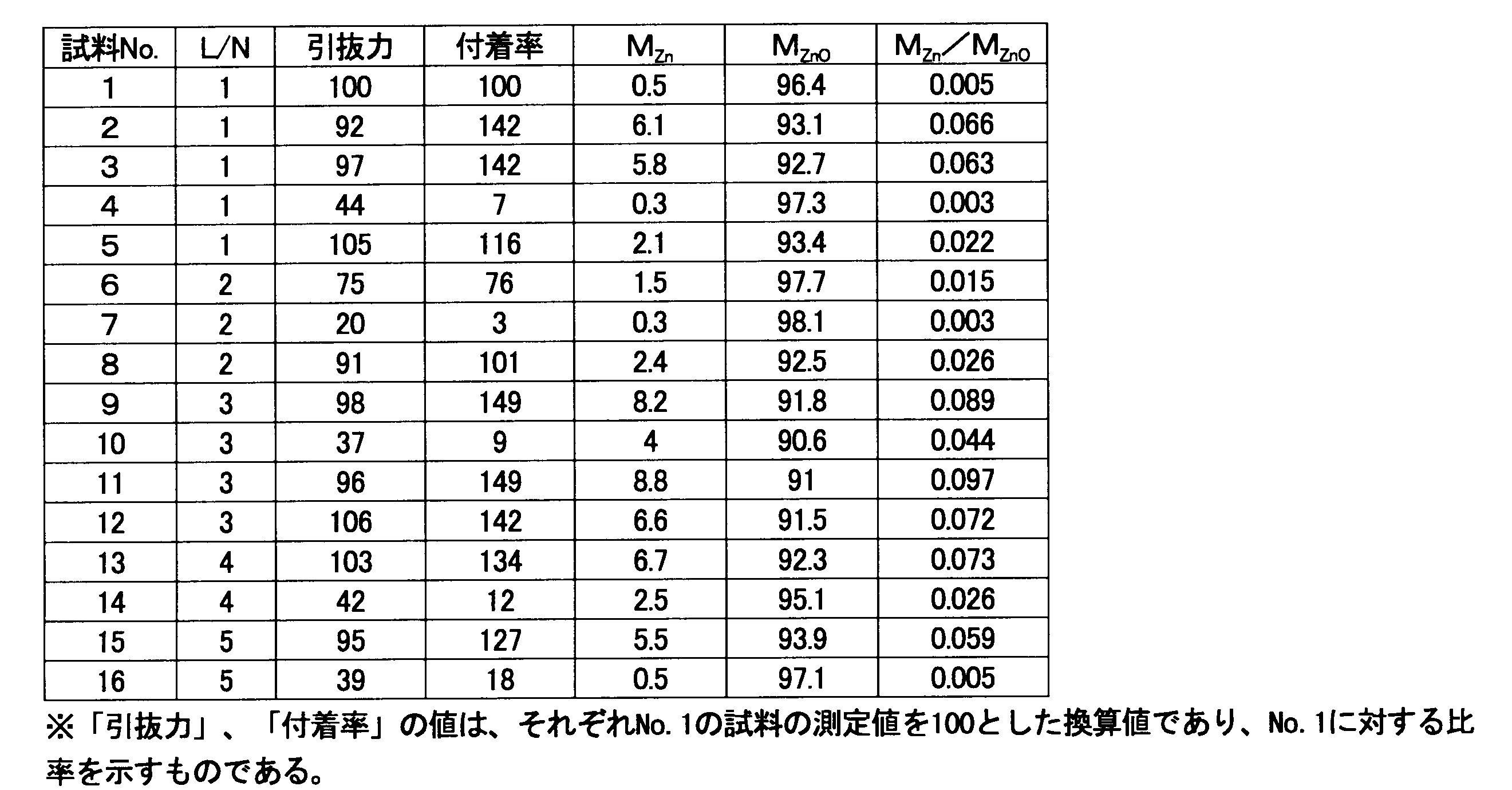
なお、試料No.1~16は、製造ロットの異なる5種類のスチールコードに対して各種処理を施して表面の金属状態の亜鉛量(MZn)や酸化物状態の亜鉛量(MZnO)を調整したものである。
具体的には、No.1~No.5、No.6~8、No.9~12、No.13~14、No.15~16のそれぞれが同一ロットのものであり、No.2は、No.1と同一ロットのスチールコードを酸洗浄して金属亜鉛比率が0.05を超える状態にさせたものであり、No.3は、No.1と同一ロットのスチールコードを電解アルカリ洗浄水で洗浄して金属亜鉛比率が0.05を超える状態にさせたものである。
さらに、No.4は、No.1と同一ロットのスチールコードを湿熱老化させたもので、No.5は、No.1と同一ロットのスチールコードをトルエンで洗浄したものである。
他の、試料もこれらと同種の調整により表面の金属亜鉛比率を調整している。
具体的には、No.1~No.5、No.6~8、No.9~12、No.13~14、No.15~16のそれぞれが同一ロットのものであり、No.2は、No.1と同一ロットのスチールコードを酸洗浄して金属亜鉛比率が0.05を超える状態にさせたものであり、No.3は、No.1と同一ロットのスチールコードを電解アルカリ洗浄水で洗浄して金属亜鉛比率が0.05を超える状態にさせたものである。
さらに、No.4は、No.1と同一ロットのスチールコードを湿熱老化させたもので、No.5は、No.1と同一ロットのスチールコードをトルエンで洗浄したものである。
他の、試料もこれらと同種の調整により表面の金属亜鉛比率を調整している。
表2のデータについて、スチールコード周りのゴムの付着率の結果を金属亜鉛比率の順に並べたものを表3に示す。
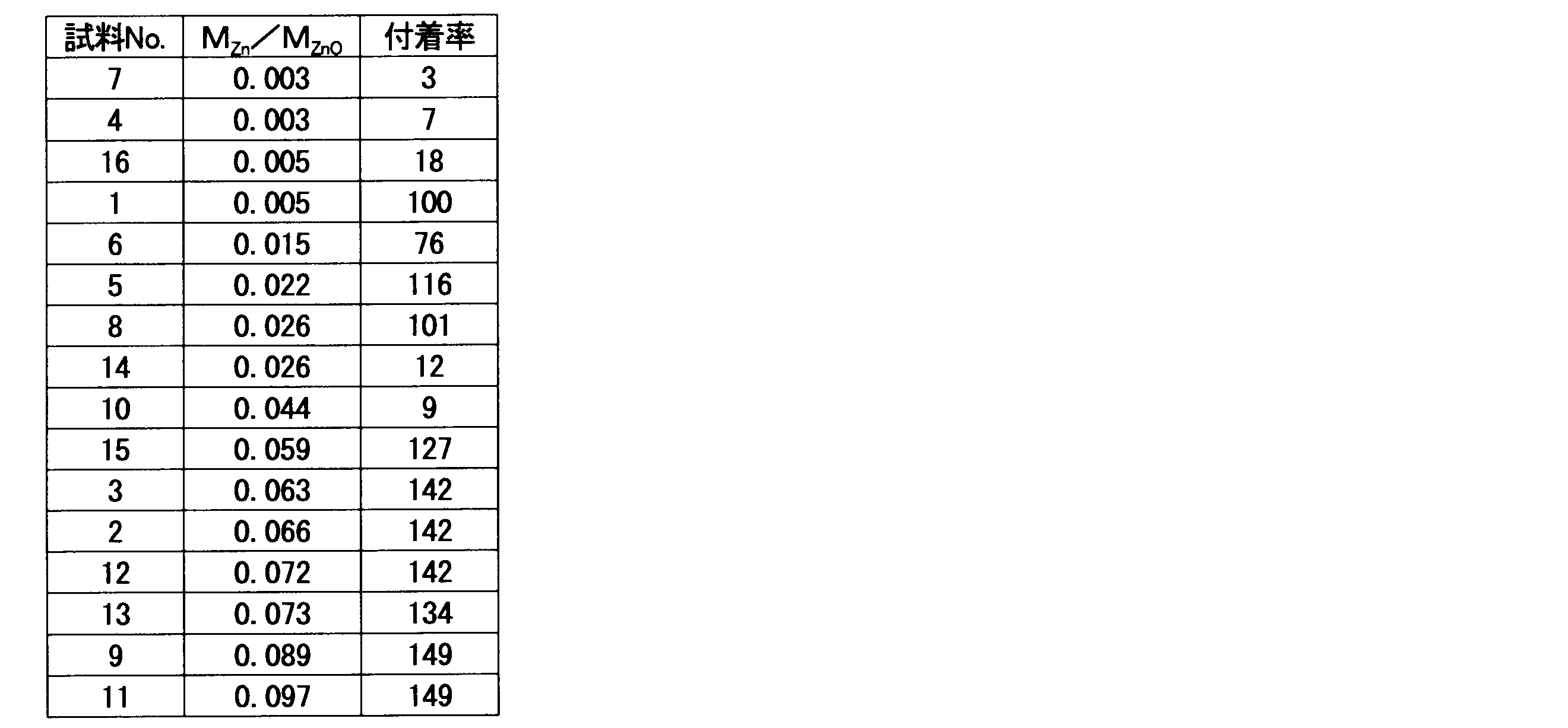
この表3からも金属亜鉛比率が0.05を超えるスチールコードは、周囲のゴムと良好なる接着状態で埋設されていることがわかる。
(プラズマ放電、レーザー照射による効果の確認)
次いで、さらに製造ロットの異なる2種類のスチールコード(No.17~20、No.21~25)を用いて、プラズマ放電、レーザー照射(2通りの条件)による効果の確認を行った。
表2と同様に評価した結果を下記表4に示す。
なお、プラズマ放電の条件と、レーザー照射の条件は下記の通り。
次いで、さらに製造ロットの異なる2種類のスチールコード(No.17~20、No.21~25)を用いて、プラズマ放電、レーザー照射(2通りの条件)による効果の確認を行った。
表2と同様に評価した結果を下記表4に示す。
なお、プラズマ放電の条件と、レーザー照射の条件は下記の通り。
1)プラズマ放電:
エア・ウォーター社製の大気圧プラズマ処理システム(リモートタイプ)を用い、10~100kHzの間において好ましい電源周波数を選定してプラズマを発生させ、プラズマ電源から3mmの地点を0.75m/分の移動速度でスチールコードを10回通過させた。
プラズマ放電は、ブローガスとなる窒素中に1リットル/分となる流量で水素ガスを流しつつ実施した。
エア・ウォーター社製の大気圧プラズマ処理システム(リモートタイプ)を用い、10~100kHzの間において好ましい電源周波数を選定してプラズマを発生させ、プラズマ電源から3mmの地点を0.75m/分の移動速度でスチールコードを10回通過させた。
プラズマ放電は、ブローガスとなる窒素中に1リットル/分となる流量で水素ガスを流しつつ実施した。
2)レーザー照射(条件1):
クリーンレーザーシステム社製の型名「CL120Q」(ランプ励起型YAGレーザー、出力122W)を用い、パルスフリケンシー:35100Hz、スキャンフリケンシー:150Hz、スキャン幅:20mm、ヘッド進行速度:50mm/秒、焦点距離:250mmの条件でスチールコードの表面にレーザー照射を実施した。
クリーンレーザーシステム社製の型名「CL120Q」(ランプ励起型YAGレーザー、出力122W)を用い、パルスフリケンシー:35100Hz、スキャンフリケンシー:150Hz、スキャン幅:20mm、ヘッド進行速度:50mm/秒、焦点距離:250mmの条件でスチールコードの表面にレーザー照射を実施した。
3)レーザー照射(条件2):
クリーンレーザーシステム社製の型名「CL120Q」(ランプ励起型YAGレーザー、出力122W)を用い、パルスフリケンシー:10000Hz、スキャンフリケンシー:130Hz、スキャン幅:15mm、ヘッド進行速度:40mm/秒、焦点距離:200mmの条件でスチールコードの表面にレーザー照射を実施した。
クリーンレーザーシステム社製の型名「CL120Q」(ランプ励起型YAGレーザー、出力122W)を用い、パルスフリケンシー:10000Hz、スキャンフリケンシー:130Hz、スキャン幅:15mm、ヘッド進行速度:40mm/秒、焦点距離:200mmの条件でスチールコードの表面にレーザー照射を実施した。
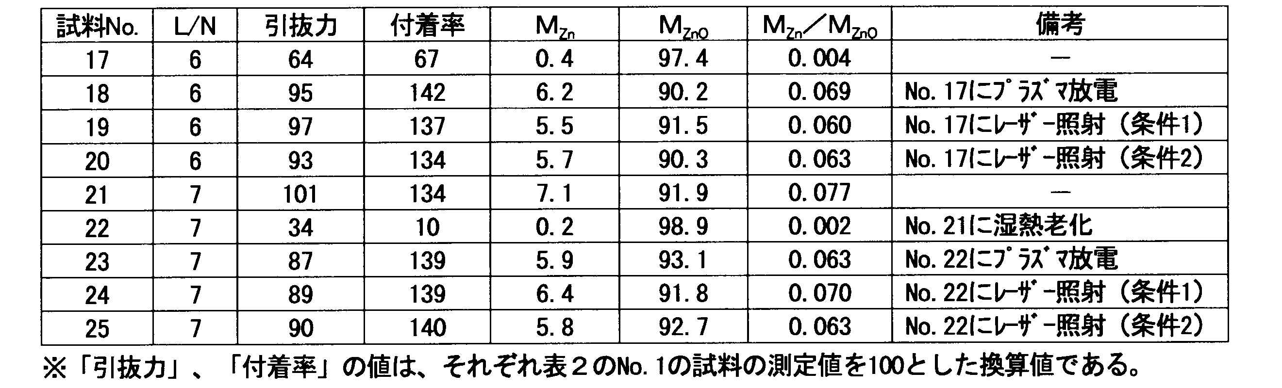
なお、試料No.18は、試料No.17と同一ロットのスチールコードに対して前記のような条件でプラズマ放電を実施したものであり、No.19、20は、それぞれ上記条件1、2のレーザー照射を実施したものである。
また、試料No.22は、試料No.21と同一ロットのスチールコードに湿熱老化を施したものであり、No.23~25は、この湿熱老化させたNo.22のスチールコードに対してプラズマ放電、レーザー照射を実施したものである。
また、試料No.22は、試料No.21と同一ロットのスチールコードに湿熱老化を施したものであり、No.23~25は、この湿熱老化させたNo.22のスチールコードに対してプラズマ放電、レーザー照射を実施したものである。
この表4からも、金属亜鉛比率が0.05を超えるスチールコードは、ゴムの付着率が高く、周囲のゴムと良好なる接着状態で埋設されていることがわかる。
得られた引抜力、及び、付着率の値と、金属亜鉛比率との関係をまとめたグラフを、図5、図6に示す。
この図からも、亜鉛メッキがされている表面における金属状態の亜鉛の量(MZn)と酸化物状態の亜鉛の量(MZnO)との割合(MZn/MZnO)が0.05以下の場合は、引抜力や付着率においてバラツキを生じており、総じて前記割合が0.05を超えるスチールコードに対して低い値となっている。
この図からも、亜鉛メッキがされている表面における金属状態の亜鉛の量(MZn)と酸化物状態の亜鉛の量(MZnO)との割合(MZn/MZnO)が0.05以下の場合は、引抜力や付着率においてバラツキを生じており、総じて前記割合が0.05を超えるスチールコードに対して低い値となっている。
(他のゴム配合における検討)
また、表1における天然ゴムとスチレン-ブタジエンゴムの比率を40/60ではなく30/70とし、カーボンブラックをHAFではなくISAFに変更したゴム未架橋ゴム組成物を用いて同様の検討を行ったが、上記に示した結果と同じ傾向の結果を得た。
また、表1における天然ゴムとスチレン-ブタジエンゴムの比率を40/60ではなく30/70とし、カーボンブラックをHAFではなくISAFに変更したゴム未架橋ゴム組成物を用いて同様の検討を行ったが、上記に示した結果と同じ傾向の結果を得た。
このことから本発明によればベルト本体を形成している架橋ゴムにスチールコードが高い接着力で接着されているコンベヤベルトを提供し得ることがわかる。
(水分の付着による影響の検討)
以下の3種類のスチールコードを用いて水分の付着によるゴム付着率の影響を確認した。
スチールコードA(STC-A):
素線7本を撚り合わせた子撚り線を7本撚り合せた直径5mmのスチールコード
スチールコードB(STC-B):
素線19本を撚り合わせた子撚り線を7本撚り合せた直径6mmのスチールコード
スチールコードC(STC-C):
STC-Bと素線構成を異ならせた19本撚りの子撚り線を7本撚り合せた直径8.5mmのスチールコード
以下の3種類のスチールコードを用いて水分の付着によるゴム付着率の影響を確認した。
スチールコードA(STC-A):
素線7本を撚り合わせた子撚り線を7本撚り合せた直径5mmのスチールコード
スチールコードB(STC-B):
素線19本を撚り合わせた子撚り線を7本撚り合せた直径6mmのスチールコード
スチールコードC(STC-C):
STC-Bと素線構成を異ならせた19本撚りの子撚り線を7本撚り合せた直径8.5mmのスチールコード
それぞれのスチールコードを、そのままの状態、及び、有機溶剤による脱脂後、水中に浸漬させた後で取り出し、スチールコードから水が滴下しなくなるまで約3分間空中に保持してスチールコードを乾燥させた(乾燥条件1)。
上記乾燥を実施したスチールコードに4.8kgf/cm2の圧縮空気を市販のプラグノズル(トラスコ社製、商品名「エアダスター TD-30」)で吹き付けさらに乾燥させた(乾燥条件2)。
これらの乾燥条件後のスチールコードの質量と、水中浸漬前のスチールコードの質量との差から水分の付着量を算出した。
下記の表5に水中浸漬前のスチールコードの質量(初期質量)を100とした場合の各乾燥後の質量(乾燥後質量)を示す。
上記乾燥を実施したスチールコードに4.8kgf/cm2の圧縮空気を市販のプラグノズル(トラスコ社製、商品名「エアダスター TD-30」)で吹き付けさらに乾燥させた(乾燥条件2)。
これらの乾燥条件後のスチールコードの質量と、水中浸漬前のスチールコードの質量との差から水分の付着量を算出した。
下記の表5に水中浸漬前のスチールコードの質量(初期質量)を100とした場合の各乾燥後の質量(乾燥後質量)を示す。

上記乾燥条件1、2のスチールコード、及び、水中浸漬をさせなかったスチールコード(初期品)を使って、先述のゴム付着率(付着率)の測定と同様の測定を行った。
その結果を下記表6に示す。
その結果を下記表6に示す。

上記に示すように、例えば、スチールコードB(STC-B)では、水分を付着させない状態では、スチールコード表面全体の70%にしかゴムの付着が見られていないのに対して、水中浸漬と乾燥とによってスチールコードに水分を付着させた場合にこの値が80%に上昇している。
このことからも水分の付着がスチールコードとゴム組成物との接着性の改善に有効であることがわかる。
このことからも水分の付着がスチールコードとゴム組成物との接着性の改善に有効であることがわかる。
なお、各乾燥条件のスチールコードをJIS K6250に規定の標準状態(23±2℃、相対湿度50±10%)に8時間から72時間の間放置した後、同様にゴム付着率の評価を実施した。
結果を、下記表7に示す。
結果を、下記表7に示す。
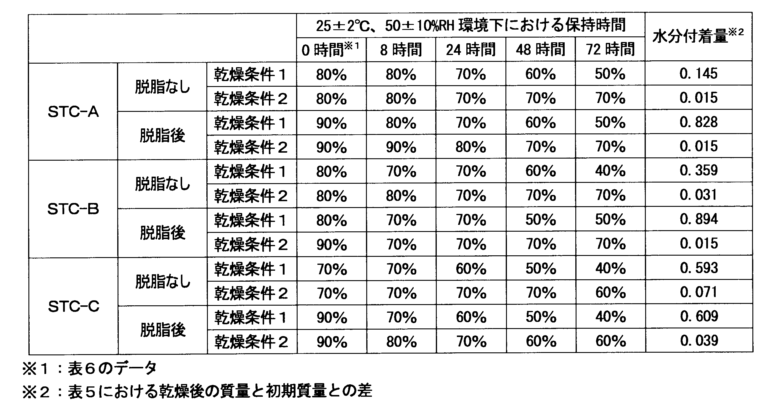
この表からも、スチールコードの質量を100とした場合における前記水分の付着量を0.01~0.3の範囲とすることで、水分を付着したまま長期放置しても接着性に低下が見られ難いことがわかる。
1:コンベヤベルト、2:カバーゴム、3:スチールコード、4:接着ゴム
Claims (9)
- 架橋ゴムによってベルト本体が形成されており、亜鉛メッキされたスチールコードが心体として前記ベルト本体中に埋設されているコンベヤベルトを製造すべく、前記ベルト本体を形成させるための未架橋ゴム組成物中に前記スチールコードを埋設させて前記未架橋ゴム組成物を架橋するコンベヤベルトの製造方法であって、
埋設させる前記スチールコードとして、前記亜鉛メッキがされている表面における金属状態の亜鉛の量(MZn)と酸化物状態の亜鉛の量(MZnO)との割合(MZn/MZnO)が0.05を超えるスチールコードを用いることを特徴とするコンベヤベルトの製造方法。 - 前記埋設前に、前記スチールコードの表面の金属状態の亜鉛の量を測定する工程を実施する請求項1記載のコンベヤベルトの製造方法。
- 亜鉛メッキされたスチールコードの表面から酸化物状態の亜鉛を除去可能な液体に前記スチールコードを接触させることによって該接触前よりも前記割合を向上させる金属亜鉛比率向上工程を前記埋設前に実施する請求項1記載のコンベヤベルトの製造方法。
- 前記未架橋ゴム組成物で作製された2枚の帯状の未架橋ゴムシートの間に前記スチールコードを挟んで熱プレスすることによって前記埋設、及び、前記架橋を実施する熱プレス工程を、前記金属亜鉛比率向上工程に続けて実施する請求項3に記載のコンベヤベルトの製造方法。
- 還元雰囲気下、亜鉛メッキされたスチールコードの表面においてプラズマ放電を発生させることによって該プラズマ放電前よりも前記割合を向上させる金属亜鉛比率向上工程を前記埋設前に実施する請求項1記載のコンベヤベルトの製造方法。
- 前記未架橋ゴム組成物で作製された2枚の帯状の未架橋ゴムシートの間に前記スチールコードを挟んで熱プレスすることによって前記埋設、及び、前記架橋を実施する熱プレス工程を、前記金属亜鉛比率向上工程に続けて実施する請求項5に記載のコンベヤベルトの製造方法。
- 還元雰囲気下、亜鉛メッキされたスチールコードの表面にレーザー光を照射して、該表面を加熱することによって前記レーザー照射前よりも前記割合を向上させる金属亜鉛比率向上工程を前記埋設前に実施する請求項1記載のコンベヤベルトの製造方法。
- 前記未架橋ゴム組成物で作製された2枚の帯状の未架橋ゴムシートの間に前記スチールコードを挟んで熱プレスすることによって前記埋設、及び、前記架橋を実施する熱プレス工程を、前記金属亜鉛比率向上工程に続けて実施する請求項7に記載のコンベヤベルトの製造方法。
- 架橋ゴムによってベルト本体が形成されており、亜鉛メッキされたスチールコードが心体として前記ベルト本体中に埋設されているコンベヤベルトであって、
請求項1乃至8のいずれか1項に記載のコンベヤベルトの製造方法によって製造されたことを特徴とするコンベヤベルト。
Applications Claiming Priority (2)
| Application Number | Priority Date | Filing Date | Title |
|---|---|---|---|
| JP2010-264015 | 2010-11-26 | ||
| JP2010264015A JP2012111623A (ja) | 2010-11-26 | 2010-11-26 | コンベヤベルトの製造方法、及び、コンベヤベルト |
Publications (1)
| Publication Number | Publication Date |
|---|---|
| WO2012070516A1 true WO2012070516A1 (ja) | 2012-05-31 |
Family
ID=46145858
Family Applications (1)
| Application Number | Title | Priority Date | Filing Date |
|---|---|---|---|
| PCT/JP2011/076764 Ceased WO2012070516A1 (ja) | 2010-11-26 | 2011-11-21 | コンベヤベルトの製造方法、及び、コンベヤベルト |
Country Status (3)
| Country | Link |
|---|---|
| JP (1) | JP2012111623A (ja) |
| TW (1) | TW201245016A (ja) |
| WO (1) | WO2012070516A1 (ja) |
Cited By (1)
| Publication number | Priority date | Publication date | Assignee | Title |
|---|---|---|---|---|
| CN110745459A (zh) * | 2019-11-21 | 2020-02-04 | 江苏凯嘉橡胶科技股份有限公司 | 非同质断面输送带 |
Citations (1)
| Publication number | Priority date | Publication date | Assignee | Title |
|---|---|---|---|---|
| JP2008156433A (ja) * | 2006-12-22 | 2008-07-10 | Bando Chem Ind Ltd | ゴム組成物およびコンベヤベルト |
-
2010
- 2010-11-26 JP JP2010264015A patent/JP2012111623A/ja active Pending
-
2011
- 2011-11-21 WO PCT/JP2011/076764 patent/WO2012070516A1/ja not_active Ceased
- 2011-11-24 TW TW100143159A patent/TW201245016A/zh unknown
Patent Citations (1)
| Publication number | Priority date | Publication date | Assignee | Title |
|---|---|---|---|---|
| JP2008156433A (ja) * | 2006-12-22 | 2008-07-10 | Bando Chem Ind Ltd | ゴム組成物およびコンベヤベルト |
Cited By (2)
| Publication number | Priority date | Publication date | Assignee | Title |
|---|---|---|---|---|
| CN110745459A (zh) * | 2019-11-21 | 2020-02-04 | 江苏凯嘉橡胶科技股份有限公司 | 非同质断面输送带 |
| CN110745459B (zh) * | 2019-11-21 | 2024-03-15 | 江苏凯嘉橡胶科技股份有限公司 | 非同质断面输送带 |
Also Published As
| Publication number | Publication date |
|---|---|
| JP2012111623A (ja) | 2012-06-14 |
| TW201245016A (en) | 2012-11-16 |
Similar Documents
| Publication | Publication Date | Title |
|---|---|---|
| KR100389218B1 (ko) | 고무조성물에대한스테인레스강체의접착력을증강시키기위해스테인레스강체를처리하는방법,이러한방법에의하여수득가능한스테인레스강체,및이를포함하는고무/강체복합물및타이어 | |
| EP3006621B1 (en) | Metal cord and rubber composite-body | |
| JP5604244B2 (ja) | ゴム−金属複合体の製造方法、ゴム−金属複合体、タイヤ、免震用のゴム支承体、工業用ベルト、及びクローラー | |
| JPH0198632A (ja) | ゴム補強材 | |
| JP2009091691A (ja) | ゴム物品補強用スチールワイヤ及びその製造方法、スチールコード、ゴム複合体並びに空気入りタイヤ | |
| JP2001260235A (ja) | ゴムと金属との接着方法、および、これを用いた構造体 | |
| JP6351902B1 (ja) | 複合部材の製造方法 | |
| EP2666816A1 (en) | Steel cord-rubber composite | |
| WO2012070516A1 (ja) | コンベヤベルトの製造方法、及び、コンベヤベルト | |
| JP2012111622A (ja) | コンベヤベルトの製造方法、及び、コンベヤベルト | |
| JP7183266B2 (ja) | 金属コード、金属コード-ゴム複合体およびコンベヤベルト | |
| JP5887171B2 (ja) | ゴム−金属複合体の製造方法 | |
| JP5415703B2 (ja) | スチールコード−ゴム複合体 | |
| EP3575449A1 (en) | Plated steel wire, steel cord, and rubber-plated steel wire composite | |
| JP6628799B2 (ja) | ゴム組成物、積層体、及びコンベアベルト | |
| JP2018119191A (ja) | めっき鋼線、スチールコード及びゴム−スチールコード複合体 | |
| JPH01177390A (ja) | ゴム製品補強用の金属線材の製造方法 | |
| JP2004263336A (ja) | ゴム接着ブラス複合体 | |
| JP2012036543A (ja) | ゴム補強用スチールワイヤの製造方法およびゴム補強用スチールワイヤ | |
| JP5887058B2 (ja) | スチールコード・ゴム複合体の製造方法 | |
| JP6220529B2 (ja) | ゴム−金属複合体の製造方法、タイヤの製造方法、工業用ベルトの製造方法、及び、ゴムクローラの製造方法 | |
| KR820001983B1 (ko) | 고무성형물 보강용 강선 | |
| JP2007186736A (ja) | 金属ワイヤの製造方法、ゴム物品補強用金属コード及び車両用タイヤ | |
| KR20180039618A (ko) | 수지밀착성이 우수한 표면처리 알루미늄재 및 이의 제조 방법, 그리고 표면처리 알루미늄재/수지의 접합체 | |
| WO2024034544A1 (ja) | 構造体及び構造体の製造方法 |
Legal Events
| Date | Code | Title | Description |
|---|---|---|---|
| 121 | Ep: the epo has been informed by wipo that ep was designated in this application |
Ref document number: 11843125 Country of ref document: EP Kind code of ref document: A1 |
|
| NENP | Non-entry into the national phase |
Ref country code: DE |
|
| 122 | Ep: pct application non-entry in european phase |
Ref document number: 11843125 Country of ref document: EP Kind code of ref document: A1 |