WO2012067149A1 - インクジェット記録装置 - Google Patents
インクジェット記録装置 Download PDFInfo
- Publication number
- WO2012067149A1 WO2012067149A1 PCT/JP2011/076409 JP2011076409W WO2012067149A1 WO 2012067149 A1 WO2012067149 A1 WO 2012067149A1 JP 2011076409 W JP2011076409 W JP 2011076409W WO 2012067149 A1 WO2012067149 A1 WO 2012067149A1
- Authority
- WO
- WIPO (PCT)
- Prior art keywords
- protective liquid
- ink
- recording apparatus
- head
- inkjet head
- Prior art date
- Legal status (The legal status is an assumption and is not a legal conclusion. Google has not performed a legal analysis and makes no representation as to the accuracy of the status listed.)
- Ceased
Links
Images

Classifications
-
- B—PERFORMING OPERATIONS; TRANSPORTING
- B41—PRINTING; LINING MACHINES; TYPEWRITERS; STAMPS
- B41J—TYPEWRITERS; SELECTIVE PRINTING MECHANISMS, i.e. MECHANISMS PRINTING OTHERWISE THAN FROM A FORME; CORRECTION OF TYPOGRAPHICAL ERRORS
- B41J2/00—Typewriters or selective printing mechanisms characterised by the printing or marking process for which they are designed
- B41J2/005—Typewriters or selective printing mechanisms characterised by the printing or marking process for which they are designed characterised by bringing liquid or particles selectively into contact with a printing material
- B41J2/01—Ink jet
- B41J2/135—Nozzles
- B41J2/165—Prevention or detection of nozzle clogging, e.g. cleaning, capping or moistening for nozzles
- B41J2/16517—Cleaning of print head nozzles
- B41J2/16552—Cleaning of print head nozzles using cleaning fluids
-
- B—PERFORMING OPERATIONS; TRANSPORTING
- B41—PRINTING; LINING MACHINES; TYPEWRITERS; STAMPS
- B41J—TYPEWRITERS; SELECTIVE PRINTING MECHANISMS, i.e. MECHANISMS PRINTING OTHERWISE THAN FROM A FORME; CORRECTION OF TYPOGRAPHICAL ERRORS
- B41J2/00—Typewriters or selective printing mechanisms characterised by the printing or marking process for which they are designed
- B41J2/005—Typewriters or selective printing mechanisms characterised by the printing or marking process for which they are designed characterised by bringing liquid or particles selectively into contact with a printing material
- B41J2/01—Ink jet
- B41J2/135—Nozzles
- B41J2/165—Prevention or detection of nozzle clogging, e.g. cleaning, capping or moistening for nozzles
- B41J2/16505—Caps, spittoons or covers for cleaning or preventing drying out
- B41J2/16508—Caps, spittoons or covers for cleaning or preventing drying out connected with the printer frame
Definitions
- the present invention relates to an ink jet recording apparatus.
- an ink jet recording apparatus is provided with an ink jet head, and ink droplets ejected from nozzles formed on the ink jet head are adhered to the print medium in a layered manner, whereby desired characters, figures, and patterns are formed on the print medium. Printing of photographs and the like is performed.
- the ink discharge property of the ink jet head may deteriorate due to the ink adhering to the nozzle due to the structure for discharging the ink. Therefore, most ink jet recording apparatuses have a maintenance mechanism for maintaining and recovering the discharge performance of the ink jet head.
- Patent Document 1 discloses a technique of filling the periphery of a nozzle tip with a cleaning liquid in order to prevent the ink from drying and solidifying at the nozzle tip protruding outside the ink jet head while ink is not discharged. ing. Specifically, at the end of ink discharge, the shutter of the cleaning liquid holding chamber surrounding the nozzle tip is closed, and the cleaning liquid holding chamber is filled with the cleaning liquid by the cleaning liquid supply pump.
- an ink jet head having a nozzle tip formed on the head surface has become mainstream.
- a maintenance method of such an inkjet head a method of forcibly discharging droplets by suction or pressurization, a method of cleaning a nozzle formation surface, a method of excessively discharging ink from a nozzle, and the like can be given.
- An inkjet head having a nozzle tip formed on the head surface has high wettability of the ink liquid with respect to the head surface. Therefore, in order to prevent ink from dripping from the head surface to the print medium, the head surface is made of Teflon (registered trademark) or the like. A water repellent layer is coated.
- the water repellent layer on the head surface may be peeled off (head attack) even if the above-described maintenance is performed. I realized that. If the water-repellent layer is peeled off, the ink picking may be bent and the image quality of the printed matter may be deteriorated. Therefore, the inventors have observed and analyzed in detail the peeling phenomenon of the water repellent layer on the head surface.
- the present inventors become acidic due to the dehydrochlorination reaction of the vinyl chloride resin of the ink component and erode the metal constituting the head, which causes the water-repellent layer to peel off. I found out.
- the present invention has been made in view of the above problems, and an object of the present invention is to provide an ink jet recording apparatus that can prevent peeling of the water-repellent layer on the head surface and can perform suitable printing at low cost even for long-term use. It is to provide.
- an inkjet recording apparatus includes an inkjet head having a nozzle surface on which nozzles for ejecting ink are formed, and a protective liquid container to which a protective liquid is supplied.
- the head is composed of a metal part and a water-repellent layer that is formed on the surface of the metal part and forms the nozzle surface.
- the nozzle surface is used as a protective liquid in the protective liquid container. It is characterized by being immersed.
- the ink jet head can immerse the nozzle surface in the protective liquid in the protective liquid container during the printing pause, so that the ink in the nozzle does not come into contact with the outside air. This suppresses ink oxidation. Specifically, even when the ink contains a vinyl chloride resin as an ink component, the vinyl chloride resin is prevented from becoming acidic due to a dehydrochlorination reaction, and thus the metal portion is prevented from being eroded. Is done.
- the protective liquid container has, on the side surface of the protective liquid container, a contact portion that makes contact with the ink jet head in which the nozzle surface is immersed in the protective liquid,
- the contact portion is made of an elastic body.
- the inside of the protective container can be sealed with the nozzle surface immersed in the protective liquid in the protective liquid container.
- ink oxidation can be more effectively suppressed.
- the ink jet recording apparatus preferably further comprises a waste liquid reservoir connected to the protective liquid container via a waste liquid flow path, and an opening / closing means for switching the open / closed state of the waste liquid flow path.
- the opening / closing means closes the waste liquid flow path when the protective liquid container is filled with the protective liquid, and opens the waste liquid flow path when the protective liquid in the protective liquid container is discarded.
- the replacement of the protective liquid in the protective container can be performed efficiently.
- the ink jet head performs a flushing operation for ejecting ink from the nozzle toward the protective liquid container.
- the protective liquid container can receive the ink ejected by the flushing operation. Therefore, it is not necessary to separately provide waste liquid means for the flushing operation, and an efficient configuration can be realized.
- the ink jet recording apparatus includes a moving means for moving the ink jet head, and the moving means so that the nozzle surface is immersed in the protective liquid in the protective liquid container while the ink jet head is not printing. It is preferable to further include movement control means for controlling the movement.
- the ink jet recording apparatus preferably further includes a protective liquid supply means for supplying a protective liquid into the protective liquid container and a supply control means for controlling the protective liquid supply means.
- the protective liquid in the protective liquid container is automatically replaced, and a new protective liquid can be used at the next immersion.
- the metal part may be made of nickel.
- the composition of the ink may contain a vinyl chloride vinyl acetate copolymer.
- Vinyl chloride vinyl acetate copolymer is a kind of vinyl chloride resin, and is one of the important compositions for constituting ink. According to the ink jet recording apparatus of the present invention, since the vinyl chloride vinyl acetate copolymer contained in the ink can be prevented from becoming acidic, head attack can be suitably prevented.
- An ink jet recording apparatus includes an ink jet head having a nozzle surface on which nozzles for ejecting ink are formed, and a protective liquid container to which a protective liquid is supplied.
- the ink jet head includes a metal portion and the metal And a water-repellent layer that forms the nozzle surface and is immersed in a protective liquid in the protective liquid container while the inkjet head is not printing. For this reason, it can suppress that the ink in a nozzle oxidizes, and can suppress corrosion of a metal part and by extension, peeling of a water-repellent layer. Therefore, the ink jet recording apparatus according to the present invention can discharge ink suitably even for long-term use.
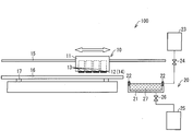
- FIG. 1 is an overall view schematically showing a configuration of an ink jet recording apparatus according to an embodiment.
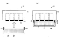
- (A) is an enlarged side view showing the ink jet head immediately before the suspension of printing
- (b) is an enlarged side view showing the ink jet head during the suspension of printing.
- (A) is an image which shows the nozzle surface in an Example
- (b) (c) is an image which shows the nozzle surface in a comparative example.
- FIG. 1 is a diagram illustrating a schematic configuration of an ink jet recording apparatus 100.
- an ink jet recording apparatus 100 includes an ink jet head 10, a head moving mechanism (moving means) 15 that moves the ink jet head 10, a support base 16 that supports a print medium, and a support base movement that moves the support base 16.
- a mechanism 17, a protection mechanism 20 for protecting the inkjet head 10, and a control unit (not shown) are provided.
- the inkjet head 10 includes a plurality of nozzles 13 formed on the lower end surface thereof. Each nozzle 13 communicates with an ink tank (not shown) via an ink tube or the like, and can appropriately discharge ink supplied from the ink tank.
- the inkjet head 10 is made of metal, which is referred to as a metal portion 11.
- a water repellent layer 12 is formed on the lower end surface of the metal part 11. That is, it can be said that the inkjet head 10 is composed of the metal part 11 and the water repellent layer 12.
- the water repellent layer 12 forms the surface (nozzle surface 14) on which the nozzles 13 of the inkjet head 10 are formed.
- a metal such as nickel can be used.
- the water repellent layer 12 is not particularly limited, but can be formed into a skin shape of about several ⁇ m to several tens of ⁇ m using a material such as Teflon (registered trademark), for example.
- the head moving mechanism 15 includes a guide rail or the like installed above the support base 16 and can freely move the inkjet head 10 to the left and right between the support base 16 and the home position on the side of the support base 16. it can.
- the home position is a printing pause position of the inkjet head 10.
- the support base 16 is composed of a flat plate or the like on which a print medium is set.
- the support table moving mechanism 17 is a mechanism for moving the support table 16 back and forth, and can be configured using, for example, a guide rail.
- the protection mechanism 20 is a mechanism that is disposed at the home position on the side of the support 16 and protects the inkjet head 10 when printing is suspended (standby). As shown in FIG. 1, the protection mechanism 20 includes a cap (protective liquid container) 21 filled with a protective liquid 27, a protective liquid tank 23 communicated with the cap 21, and a waste liquid tank 25 communicated with the cap 21. ing.
- the cap 21 is a container provided at the home position beside the support base 16.
- the upper side of the cap 21 is open, and the protective liquid 27 is stored inside the cap 21.
- the cap 21 is configured to be able to rise from the position shown in FIG. 1, and when the ink jet head 10 moves to the home position, the cap surface 21 rises, so that the nozzle surface 14 cleans the cleaning liquid in the cap 21. Soaked in.
- Any protective liquid 27 may be used as long as it protects the nozzle surface 14 from erosion, and a commercially available cleaning liquid can be used.
- the present invention is not limited to raising the cap 21, and the head moving mechanism 15 may lower the inkjet head 10 at the home position.
- the cap 21 has a contact portion 22 that contacts the inkjet head 10 on the inner side surface when the nozzle surface 14 is immersed.
- the contact portion 22 is made of an elastic body, and it is preferable that the inner side of the cap 21 be sealed by the ink jet head 10 and the contact portion 22 being in close contact with each other when the nozzle surface 14 is immersed.
- the cap 21 may be comprised not only of the contact part 22 but the elastic body as a whole.
- the protective liquid tank 23 communicates with the cap 21, and the protective liquid 27 can be supplied to the cap 21.
- a supply valve 24 is provided in the flow path between the cap 21 and the protective liquid tank 23.
- the protective liquid tank 23 and the supply valve 24 constitute protective liquid supply means, and the supply valve 24 establishes communication between the cap 21 and the protective liquid tank 23 when supplying the protective liquid.
- this invention is not limited to having the said protective liquid supply means, An operator may fill a protective liquid directly into the cap 21 using a dropper etc.
- the waste liquid tank 25 is a waste liquid reservoir for the protective liquid that has been discharged from the cap 21.
- a waste liquid valve (opening / closing means) 26 is provided in the waste liquid flow path between the cap 21 and the waste liquid tank 25. The waste liquid valve 26 disconnects the communication between the cap 21 and the waste liquid tank 25 when the cap 21 is filled with the protective liquid 27, and sets the communication between the cap 21 and the waste liquid tank 25 when the protective liquid 27 in the cap 21 is discarded.
- the waste liquid tank 25 may be provided with a decompression means for efficiently discarding the protective liquid 27 in the cap 21.
- the ink jet recording apparatus 100 includes a control unit (movement control means, supply control means) for controlling each member.
- the control unit can control the movement of the inkjet head 10 and the support 16, the ink ejection of the inkjet head 10, the supply or disposal of the protective liquid 27 in the protection mechanism 20, etc. by controlling each member.
- the inkjet head 10 may automatically move so that the nozzle surface 14 is immersed in the protective liquid 27 after completion of printing.
- the protective liquid 27 may be automatically supplied to the cap 21 by the control unit controlling the supply valve 24.
- the operations of these members are not limited to being automatically performed by the control unit, and may be performed manually.
- the support base moving mechanism 17 sends the support base 16 forward, and the head moving mechanism 15 reciprocates the ink jet head 10 in the left-right direction. Ink is discharged from the nozzle. Thereby, the ink jet recording apparatus 100 can form an image such as a character or a graphic according to the printing program on the printing medium on the support 16.
- the head moving mechanism 15 moves the inkjet head 10 to the home position.
- FIG. 2A is a side view showing a state where the inkjet head 10 is stopped at the home position.
- the inkjet head 10 performs maintenance of the nozzle 13 by discharging ink by a flushing operation.
- the cap 21 functions as a receiving portion for the ink ejected from the inkjet head 10. The ink received by the cap 21 is discharged into the waste liquid tank 25.
- the inkjet head 10 stands by at the home position until the next image formation is started.
- the protective liquid 27 is supplied from the protective liquid tank 23 into the cap 21 with the waste liquid valve 26 closed.
- the cap 21 rises and the nozzle surface 14 is immersed in the protective liquid 27 in the cap 21.
- FIG. 2 (b) is a side view showing the inkjet head 10 during printing suspension.
- the nozzle surface 14 of the inkjet head 10 remains immersed in the protective liquid 27 in the cap 21 during the printing pause. Therefore, the ink in the nozzles 13 of the inkjet head 10 is suppressed from being oxidized without being exposed to the outside air during the printing pause, so that the erosion of the nozzle surface 11 of the inkjet head 10 is suppressed.
- the inkjet head 10 abuts against the abutting portion 22 of the cap 21 to seal the inside of the cap 21. Thereby, it is possible to more suitably prevent the ink in the nozzle 13 of the inkjet head 10 from coming into contact with the outside air.
- the cap 21 When the standby is completed and the next printing is started, the cap 21 is lowered, the ink jet head 10 is pulled up from the protective liquid 27 in the cap 21, and then the waste liquid valve 26 is opened so that the protective liquid 27 is discharged. Waste liquid is discharged to the waste liquid tank 25.
- the ink jet recording apparatus 100 according to the present embodiment can perform suitable printing even for long-term use.
- the inkjet recording apparatus 100 according to the present embodiment can be expected as an apparatus that performs low-cost and stable printing for a long period of time in an environment where ink oxidation is fast, such as a high-temperature and high-humidity environment.
- Example ⁇ As an example, the ink jet recording apparatus 100 according to the present invention was used, and the ink jet head 10 was left for 7 days in a printing pause state in an environment of a temperature of 45 ° C. and a humidity of 90%, and then the nozzle surface 14 was observed. In the example, the nozzle surface 14 was immersed in the protective liquid 27 in the cap 21 while the inkjet head 10 was not printing.
- the same configuration as that of the inkjet recording apparatus 100 according to the present invention was used.
- the inkjet head 10 was left for 7 days in a printing pause state, and then the nozzle surface 14 was observed.
- the protection mechanism 20 was not used, and the nozzle surface 14 was left exposed to the atmosphere while the inkjet head 10 was not printing.
- BMGAC 2-butoxyethyl acetate
- PMA propylene glycol monomethyl ether acetate
- VYHD Union Carbide Japan
- W100-EL manufactured by DIC Corporation
- Trade name epoxidized soybean oil
- SS-39000 manufactured by Nippon Lubrizol Co., Ltd.
- dispersant VS # 8832: manufactured by Nitto Kasei Co., Ltd., trade name, tin-based additive.
- VYHD vinyl chloride vinyl acetate copolymer
- FIGS. 3 (b) and 3 (c) are images showing the nozzle surface observed in the comparative example.
- the water-repellent layer forming the nozzle surface was not peeled off in the example, but the water-repellent layer around the nozzle was peeled off in the comparative example. Therefore, according to the protection mechanism 20 according to the present invention, it is clear that the ink-jet head 10 can be used stably for a long period of time without peeling off the water repellent layer even under adverse conditions of high temperature and humidity. It was.
- the present invention can be suitably used as a protection mechanism for an inkjet head.
Landscapes
- Ink Jet (AREA)
- Particle Formation And Scattering Control In Inkjet Printers (AREA)
Abstract
長期間の使用においても好適な印刷を実施できるインクジェット記録装置を提供する。 本発明に係るインクジェット記録装置(100)は、ノズルが形成されたノズル面(14)を有するインクジェットヘッド(10)と、保護液が供給されるキャップ(21)とを備えている。インクジェットヘッド(10)は、金属部(11)と、金属部(11)の表面に形成されてノズル面(14)を成す撥水層(12)とから構成されている。インクジェットヘッド(10)のノズル面(14)は、印刷休止中、キャップ(21)内の保護液に浸漬された状態を維持する。
Description
本発明はインクジェット記録装置に関するものである。
一般に、インクジェット記録装置にはインクジェットヘッドが設置されており、このインクジェットヘッドに形成されたノズルから吐出されたインク滴を印刷媒体に層状に付着させることによって、印刷媒体に所望の文字や図形、模様、写真等の印刷が行われる。
このようなインクジェットヘッドでは、インクを吐出する構造上、ノズルにインクが固着することによってインクジェットヘッドのインク吐出性が悪化してしまうことがある。そこで、大抵のインクジェット記録装置は、インクジェットヘッドの吐出性を維持及び回復するためのメンテナンス機構を有している。
例えば、特許文献1には、インクの吐出を行わない間、インクジェットヘッドの外側に突出したノズル先端にインクが乾燥・固化することを防ぐため、当該ノズル先端の周辺を洗浄液で満たす技術が開示されている。具体的には、インク吐出の終了時、ノズル先端を囲う洗浄液保留室のシャッタを閉鎖し、洗浄液供給ポンプにより洗浄液を洗浄液保留室に充填させている。
ところが、特許文献1に開示された構成では、ノズル先端と印刷媒体との間に洗浄液保留室の壁が介在しているため、ノズル先端と印刷媒体との間の間隔を小さくできず、印刷精度を向上させることが難しい。とは言え、特許文献1に開示された構成では、ノズル先端が外側に突出しているため、洗浄液保留室の壁が介在しないとノズルが破損し易くなってしまう。
そこで、近年では、ノズル先端がヘッド表面に形成されたインクジェットヘッドが主流になっている。このようなインクジェットヘッドのメンテナンス方法としては、吸引又は加圧などにより液滴を強制排出する方法、ノズル形成面を清掃する方法、及びノズルからインクを余剰に吐出する方法などが挙げられる。
ノズル先端がヘッド表面に形成されたインクジェットヘッドでは、ヘッド表面に対するインク液の濡れ性が高いため、ヘッド表面から印刷媒体へのインクたれを防止するために、ヘッド表面にテフロン(登録商標)などの撥水層がコーティングされている。
本発明者らは、このようなインクジェットヘッドを長期間使用していると、上述のようなメンテナンスを行っていたとしても、ヘッド表面の撥水層が剥離(ヘッドアタック)してしまう場合があることに気が付いた。撥水層が剥離するとインク摘の飛行曲がり等が発生し、印刷物の画質が悪化する要因になってしまう。そこで、本発明者らは、ヘッド表面の撥水層の剥離現象について詳しく観察、解析を行った。
その結果、本発明者らは、インク成分の塩化ビニル系樹脂が脱塩酸反応を起こすことにより酸性になってヘッドを構成する金属を浸食してしまい、これが撥水層の剥離の原因になることを突き止めた。
単にインクの酸化を抑制するためには、例えばインクに酸化防止剤等の添加物を加えてインク自体の性質を改良する方法が考えられる。しかしながら、添加物を加えて改良したインクはコストが上昇するため、インクが消耗品であることを考慮すると好ましくない。
本発明は、上記課題を鑑みてなされたものであり、その目的は、ヘッド表面の撥水層の剥離を防止し、長期間の使用においても好適な印刷を低コストで実施できるインクジェット記録装置を提供することにある。
本発明に係るインクジェット記録装置は、上記の課題を解決するために、インクを吐出するノズルが形成されたノズル面を有するインクジェットヘッドと、保護液が供給される保護液容器とを備え、前記インクジェットヘッドは、金属部と、当該金属部の表面に形成されて前記ノズル面を成す撥水層とから構成され、前記インクジェットヘッドの印刷休止中、前記ノズル面は前記保護液容器内の保護液に浸漬されることを特徴としている。
前記構成によれば、インクジェットヘッドは、印刷休止中、ノズル面を保護液容器内の保護液に浸漬させることができるため、ノズル内のインクは外気に触れることがなくなる。これによってインクの酸化が抑制される。具体的には、インクがインク成分として塩化ビニル系樹脂を含む場合であっても、塩化ビニル系樹脂が脱塩酸反応して酸性になることが抑制され、ひいては金属部が浸食されることが抑制される。
したがって、前記構成によれば、ヘッド表面の撥水層の剥離を抑制し、長期間の使用においても好適な印刷を低コストで実施できるインクジェット記録装置を提供することができる。
また、本発明に係るインクジェット記録装置では、前記保護液容器は、当該保護液容器の側面において、前記ノズル面が保護液に浸漬された前記インクジェットヘッドと当接する当接部を有しており、前記保護液容器は、少なくとも前記当接部が弾性体から構成されていることが好ましい。
前記構成によれば、ノズル面が保護液容器内の保護液に浸漬された状態で、保護容器内を密閉することができる。これによってインクの酸化をより効果的に抑制することができる。
また、本発明に係るインクジェット記録装置は、前記保護液容器に廃液流路を介して連通した廃液溜め部と、前記廃液流路の開閉状態を切り替える開閉手段とをさらに備えることが好ましい。
前記構成によれば、開閉手段は保護液容器内に保護液を満たす場合に廃液流路を閉状態にし、保護液容器内の保護液を廃棄する場合に廃液流路を開状態にすることによって、保護容器内の保護液の入れ替えを効率的に行うことができる。
また、本発明に係るインクジェット記録装置は、前記インクジェットヘッドは、前記保護液容器に向かって前記ノズルからインクを吐出するフラッシング動作を行うことが好ましい。
前記構成によれば、保護液容器がフラッシング動作により吐出されたインクを受けることができる。よって、フラッシング動作のための廃液手段を別途設ける必要はなく、効率的な構成を実現することができる。
また、本発明に係るインクジェット記録装置は、前記インクジェットヘッドを移動させる移動手段と、前記インクジェットヘッドの印刷休止中に前記ノズル面が前記保護液容器内の保護液に浸漬するように、前記移動手段を制御する移動制御手段をさらに備えていることが好ましい。
前記構成によれば、印刷休止中におけるインクジェットヘッドの保護を自動的に行うことができる。
また、本発明に係るインクジェット記録装置は、前記保護液容器内に保護液を供給する保護液供給手段と、前記保護液供給手段を制御する供給制御手段とをさらに備えていることが好ましい。
前記構成によれば、保護液容器内の保護液を自動的に入れ替え、次回の浸漬時に新しい保護液を使用することができる。
なお、本発明に係るインクジェット記録装置において、前記金属部はニッケルから構成されてもよい。
また、本発明に係るインクジェット記録装置において、前記インクの組成は、塩化ビニル酢酸ビニル共重合体を含有していてもよい。
塩化ビニル酢酸ビニル共重合体は、塩化ビニル系樹脂の1種であり、インクを構成するための重要な組成の1つである。本発明に係るインクジェット記録装置によれば、インクに含まれる塩化ビニル酢酸ビニル共重合体が酸性になることを抑制することができるため、ヘッドアタックを好適に防止することができる。
本発明に係るインクジェット記録装置は、インクを吐出するノズルが形成されたノズル面を有するインクジェットヘッドと、保護液が供給される保護液容器とを備え、前記インクジェットヘッドは、金属部と、当該金属部の表面に形成されて前記ノズル面を成す撥水層とから構成され、前記インクジェットヘッドの印刷休止中、前記ノズル面は前記保護液容器内の保護液に浸漬される。このため、ノズル内のインクが酸化することを抑制し、金属部の腐食、ひいては撥水層の剥離を抑制することができる。よって、本発明に係るインクジェット記録装置は、長期間の使用においても好適にインクを吐出することができる。
以下、図面を参照して本発明の好ましい実施形態について説明する。
(インクジェット記録装置100の構成)
まず、インクジェット記録装置100の概略的な構成について図1を参照して以下に説明する。図1は、インクジェット記録装置100の概略的な構成を示す図である。
まず、インクジェット記録装置100の概略的な構成について図1を参照して以下に説明する。図1は、インクジェット記録装置100の概略的な構成を示す図である。
図1に示すように、インクジェット記録装置100は、インクジェットヘッド10、インクジェットヘッド10を移動させるヘッド移動機構(移動手段)15、印刷媒体を支持する支持台16、支持台16を移動させる支持台移動機構17、インクジェットヘッド10を保護するための保護機構20、および制御部(図示しない)を備えている。
インクジェットヘッド10は、その下端表面に形成された複数のノズル13を備えている。各ノズル13はインクチューブ等を介してインクタンク(図示しない)と連通しており、インクタンクから供給されたインクを適宜吐出することができる。
また、インクジェットヘッド10は、その大部分が金属によって構成されており、これを金属部11と称する。金属部11の下端表面には撥水層12が形成されている。すなわち、インクジェットヘッド10は、金属部11と撥水層12とから構成されていると言うことができる。撥水層12は、インクジェットヘッド10におけるノズル13が形成された表面(ノズル面14)を成している。金属部11の材料としては、ニッケル等の金属を用いることができる。また撥水層12は、特に限定されないが、例えばテフロン(登録商標)等の材料を用いて数μm~数十μm程度のスキン状に形成することができる。
ヘッド移動機構15は、支持台16上方に架設されたガイドレール等を備えており、インクジェットヘッド10を支持台16上から支持台16脇のホームポジションまでの間において左右に自在に移動させることができる。なお、ホームポジションとは、インクジェットヘッド10の印刷休止位置である。ヘッド移動機構15がインクジェットヘッド10をホームポジションに移動させた際、インクジェットヘッド10はキャップ21に対向して配置される。
支持台16は、上面に印刷媒体がセットされる平板等から構成される。支持台移動機構17は、支持台16を前後に移動させる機構であり、例えばガイドレール等を用いて構成することが可能である。
保護機構20は、支持台16脇のホームポジションに配置され、印刷休止時(待機時)にインクジェットヘッド10の保護を行う機構である。図1に示すように、保護機構20は、保護液27が充填されるキャップ(保護液容器)21と、キャップ21に連通した保護液タンク23と、キャップ21に連通した廃液タンク25とを備えている。
キャップ21は、支持台16脇のホームポジションに設けられた容器である。キャップ21の上側は開口しており、その内側には保護液27が貯留される。また、キャップ21は図1に示す位置よりも上昇可能なように構成されており、インクジェットヘッド10がホームポジションに移動した際、キャップ21が上昇することにより、ノズル面14がキャップ21内の洗浄液に浸漬される。保護液27としては、ノズル面14を浸食から保護するものであればよく、市販の洗浄液を利用することができる。
なお、本発明はキャップ21を上昇させることに限定されず、ヘッド移動機構15が、ホームポジションにおいてインクジェットヘッド10を下降させてもよい。
また、キャップ21は、ノズル面14の浸漬時、その内側側面においてインクジェットヘッド10と当接する当接部22を有する。当接部22は弾性体から構成され、ノズル面14の浸漬時には、インクジェットヘッド10と当接部22とが密着することによってキャップ21の容器内側が密閉されることが好ましい。なお、キャップ21は、当接部22だけでなく、全体的に弾性体から構成されてもよい。
保護液タンク23はキャップ21と連通しており、保護液27をキャップ21に供給することができる。キャップ21と保護液タンク23との間の流路には供給弁24が設けられている。保護液タンク23及び供給弁24は保護液供給手段を構成しており、供給弁24は、保護液供給の際、キャップ21と保護液タンク23との間の連通を継状態にする。
なお、本発明は上記保護液供給手段を有することに限定されず、作業者がスポイト等を用いて直接キャップ21へ保護液を満たしてもよい。
廃液タンク25は、キャップ21から廃液された保護液の廃液溜めである。キャップ21と廃液タンク25との間の廃液流路には廃液弁(開閉手段)26が設けられている。廃液弁26は、キャップ21に保護液27を満たすときにはキャップ21と廃液タンク25との間の連通を断状態にし、キャップ21内の保護液27を廃棄するときには両者の連通を継状態にする。
なお、廃液タンク25には、キャップ21内の保護液27を効率的に廃棄するための減圧手段が設けられていてもよい。
また、インクジェット記録装置100は、各部材を制御する制御部(移動制御手段、供給制御手段)を備えている。制御部は、各部材を制御することによって、インクジェットヘッド10および支持台16の移動、インクジェットヘッド10のインク吐出、ならびに、保護機構20における保護液27の供給または廃棄などを制御することができる。
例えば、制御部がヘッド移動機構15を制御することによって、印刷終了後にノズル面14が保護液27に浸漬するようにインクジェットヘッド10が自動的に移動してもよい。また、制御部が供給弁24を制御することによって、キャップ21へ保護液27が自動的に供給されてもよい。なお、これらの各部材の動作は、制御部によって自動的に行われることに限定されず、手動によって行われていもよい。
(インクジェット記録装置100の動作)
次に、以上のように構成されたインクジェット記録装置100におけるインク吐出動作およびメンテナンス動作について説明する。
次に、以上のように構成されたインクジェット記録装置100におけるインク吐出動作およびメンテナンス動作について説明する。
インクジェット記録装置100が画像を形成する際、支持台移動機構17が支持台16を前方へ送り、ヘッド移動機構15がインクジェットヘッド10を左右方向に往復移動させるのと同時に、インクジェットヘッド10がノズル13からインクを吐出する。これによって、インクジェット記録装置100は、支持台16上の印刷媒体に印刷プログラムに応じた文字や図形等の画像を形成することができる。インクジェットヘッド10が印刷終了点に達すると、ヘッド移動機構15はインクジェットヘッド10をホームポジションに移動させる。
図2(a)は、インクジェットヘッド10がホームポジションに停止した状態を示す側面図である。図2(a)に示す状態において、インクジェットヘッド10はフラッシング動作によりインクを吐出することによって、ノズル13のメンテナンスを行う。このときキャップ21はインクジェットヘッド10から吐出されたインクの受け部として機能する。キャップ21が受けたインクは廃液タンク25に廃液される。
メンテナンス後、インクジェットヘッド10は次の画像の形成を開始するまで、そのままホームポジションに待機する。この待機に先立ち、廃液弁26が閉じた状態で保護液27が保護液タンク23からキャップ21内に供給される。次いで、図2(a)の矢印に示すように、キャップ21が上昇し、ノズル面14をキャップ21内の保護液27に浸漬させる。
図2(b)は、印刷休止中のインクジェットヘッド10を示す側面図である。図2(b)に示すように、印刷休止中、インクジェットヘッド10のノズル面14はキャップ21内の保護液27に浸漬されたままである。よって、印刷休止中にインクジェットヘッド10のノズル13内のインクは外気に触れることなく酸化が抑制されるため、インクジェットヘッド10のノズル面11の浸食は抑制される。
また、図2(b)に示すように、インクジェットヘッド10はキャップ21の当接部22と当接し、キャップ21内を密閉することが好ましい。これによって、インクジェットヘッド10のノズル13内のインクが外気に触れることをより好適に防止することができる。
待機が終了し、次の印刷を開始する場合には、キャップ21が下降し、インクジェットヘッド10がキャップ21内の保護液27から引き上げられた後、廃液弁26が開けられることによって保護液27が廃液タンク25に廃液される。
以上の動作によれば、本実施形態に係るインクジェット記録装置100は、長期間の使用においても好適な印刷を実施できる。特に、本実施形態に係るインクジェット記録装置100は、高温多湿の環境などインクの酸化が早い環境下において、低コストで長期間安定した印刷を実施する装置として期待することができる。
〔実施例〕
実施例として、本発明に係るインクジェット記録装置100を用い、温度45℃、湿度90%の環境下で、インクジェットヘッド10を印刷休止状態のまま7日間放置した後、そのノズル面14を観測した。実施例では、インクジェットヘッド10の印刷休止中、ノズル面14をキャップ21内の保護液27に浸漬したままにした。
実施例として、本発明に係るインクジェット記録装置100を用い、温度45℃、湿度90%の環境下で、インクジェットヘッド10を印刷休止状態のまま7日間放置した後、そのノズル面14を観測した。実施例では、インクジェットヘッド10の印刷休止中、ノズル面14をキャップ21内の保護液27に浸漬したままにした。
一方、比較例として、本発明に係るインクジェット記録装置100と同様の構成を用い、同環境下で、インクジェットヘッド10を印刷休止状態のまま7日間放置した後、そのノズル面14を観測した。比較例では、保護機構20を利用せず、インクジェットヘッド10の印刷休止中、ノズル面14を大気に晒した状態のままにした。
また、実施例および比較例では、以下の表1に示す組成を有するインク組成物を用いた。

なお、表1において、BMGAC:2-ブトキシエチルアセテート、PMA:プロピレングリコールモノメチルエーテルアセテート、VYHD:ユニオンカーバイト日本社製、商品名、塩化ビニル酢酸ビニル共重合体、W100-EL:DIC株式会社製、商品名、エポキシ化大豆油、SS-39000:日本ルーブリゾール株式会社製、商品名、分散剤、VS#8832:日東化成株式会社製、商品名、スズ系添加剤である。
上記インク組成物のうち、VYHD(塩化ビニル酢酸ビニル共重合体)は、塩化ビニル系樹脂の1種であり、酸性になるとヘッドアタックの原因物質になるものである。
図3(a)は、実施例において観察されたノズル面を示す画像であり、図3(b)(c)は、比較例において観察されたノズル面を示す画像である。
図3(a)~(c)に示すように、実施例ではノズル面を成す撥水層が剥離していないが、比較例ではノズル周辺の撥水層が剥離していた。したがって、本発明に係る保護機構20によれば、高温多湿の悪条件においてであっても撥水層が剥離することなく、インクジェットヘッド10は長期間安定して利用可能であることが明らかとなった。
本発明は、インクジェットヘッドの保護機構として好適に利用することができる。
10 インクジェットヘッド
11 金属部
12 撥水層
13 ノズル
14 ノズル面
15 ヘッド移動機構
16 支持台
17 支持台移動機構
20 保護機構
21 キャップ
22 当接部
23 保護液タンク
24 供給弁
25 廃液タンク
26 廃液弁
100 インクジェット記録装置
11 金属部
12 撥水層
13 ノズル
14 ノズル面
15 ヘッド移動機構
16 支持台
17 支持台移動機構
20 保護機構
21 キャップ
22 当接部
23 保護液タンク
24 供給弁
25 廃液タンク
26 廃液弁
100 インクジェット記録装置
Claims (7)
- インクを吐出するノズルが形成されたノズル面を有するインクジェットヘッドと、
保護液が供給される保護液容器とを備え、
前記インクジェットヘッドは、金属部と、当該金属部の表面に形成されて前記ノズル面を成す撥水層とから構成され、
前記インクジェットヘッドの印刷休止中、前記ノズル面は前記保護液容器内の保護液に浸漬されることを特徴とするインクジェット記録装置。 - 前記保護液容器は、当該保護液容器の側面において、前記ノズル面が保護液に浸漬された前記インクジェットヘッドと当接する当接部を有しており、
前記保護液容器は、少なくとも前記当接部が弾性体から構成されていることを特徴とする請求項1に記載のインクジェット記録装置。 - 前記保護液容器に廃液流路を介して連通した廃液溜め部と、
前記廃液流路の開閉状態を切り替える開閉手段とをさらに備えること
を特徴とする請求項1または2に記載のインクジェット記録装置。 - 前記インクジェットヘッドは、前記保護液容器に向かって前記ノズルからインクを吐出するフラッシング動作を行うことを特徴とする請求項1に記載のインクジェット記録装置。
- 前記インクジェットヘッドを移動させる移動手段と、
前記インクジェットヘッドの印刷休止中に前記ノズル面が前記保護液容器内の保護液に浸漬するように、前記移動手段を制御する移動制御手段をさらに備えていることを特徴とする請求項1に記載のインクジェット記録装置。 - 前記保護液容器内に保護液を供給する保護液供給手段と、
前記保護液供給手段を制御する供給制御手段とをさらに備えていることを特徴とする請求項1に記載のインクジェット記録装置。 - 前記インクの組成は、塩化ビニル酢酸ビニル共重合体を含有していることを特徴とする請求項1に記載のインクジェット記録装置。
Priority Applications (1)
| Application Number | Priority Date | Filing Date | Title |
|---|---|---|---|
| CN201180055298.0A CN103221219B (zh) | 2010-11-17 | 2011-11-16 | 喷墨打印装置 |
Applications Claiming Priority (2)
| Application Number | Priority Date | Filing Date | Title |
|---|---|---|---|
| JP2010256897A JP5802381B2 (ja) | 2010-11-17 | 2010-11-17 | インクジェット記録装置 |
| JP2010-256897 | 2010-11-17 |
Publications (1)
| Publication Number | Publication Date |
|---|---|
| WO2012067149A1 true WO2012067149A1 (ja) | 2012-05-24 |
Family
ID=46084072
Family Applications (1)
| Application Number | Title | Priority Date | Filing Date |
|---|---|---|---|
| PCT/JP2011/076409 Ceased WO2012067149A1 (ja) | 2010-11-17 | 2011-11-16 | インクジェット記録装置 |
Country Status (3)
| Country | Link |
|---|---|
| JP (1) | JP5802381B2 (ja) |
| CN (1) | CN103221219B (ja) |
| WO (1) | WO2012067149A1 (ja) |
Cited By (1)
| Publication number | Priority date | Publication date | Assignee | Title |
|---|---|---|---|---|
| CN112677655A (zh) * | 2020-12-30 | 2021-04-20 | 烟台华兴纸制品有限公司 | 一种全自动数码印刷机 |
Families Citing this family (6)
| Publication number | Priority date | Publication date | Assignee | Title |
|---|---|---|---|---|
| JP6368565B2 (ja) * | 2014-07-07 | 2018-08-01 | 株式会社ミマキエンジニアリング | インクジェット記録装置およびインクジェット記録方法 |
| JP6465060B2 (ja) * | 2016-03-31 | 2019-02-06 | ブラザー工業株式会社 | 印刷装置 |
| CN106915162B (zh) * | 2017-03-10 | 2019-06-18 | 深圳弘美数码纺织技术有限公司 | 一种打印喷头维护装置 |
| JP6508242B2 (ja) * | 2017-03-30 | 2019-05-08 | ブラザー工業株式会社 | 印刷装置 |
| JP7280677B2 (ja) * | 2018-09-27 | 2023-05-24 | 株式会社日立産機システム | インクジェット記録装置 |
| JP2020121488A (ja) * | 2019-01-31 | 2020-08-13 | 京セラドキュメントソリューションズ株式会社 | 画像形成装置及び画像形成プログラム |
Citations (7)
| Publication number | Priority date | Publication date | Assignee | Title |
|---|---|---|---|---|
| JP2001018408A (ja) * | 1999-07-09 | 2001-01-23 | Seiko Epson Corp | インクジェット式記録装置および同装置における保湿液吐出制御方法 |
| JP2001138540A (ja) * | 1999-11-10 | 2001-05-22 | Nec Corp | 印字ヘッド保護装置およびその動作制御方法 |
| JP2002127439A (ja) * | 2000-10-26 | 2002-05-08 | Pentel Corp | インクジェットヘッドのキャッピング方法 |
| JP2004167772A (ja) * | 2002-11-19 | 2004-06-17 | Matsushita Electric Ind Co Ltd | インクジェット式記録装置 |
| JP2005212378A (ja) * | 2004-01-30 | 2005-08-11 | Seiko Epson Corp | 液滴吐出装置、液滴吐出装置の処理方法、及びデバイス製造方法 |
| JP2007169492A (ja) * | 2005-12-22 | 2007-07-05 | Seiko Epson Corp | インクジェット記録用油性インク組成物 |
| JP2010150465A (ja) * | 2008-12-26 | 2010-07-08 | Toyo Ink Mfg Co Ltd | 発光ダイオード硬化型インクジェットインキおよび印刷物 |
Family Cites Families (3)
| Publication number | Priority date | Publication date | Assignee | Title |
|---|---|---|---|---|
| JP2008208171A (ja) * | 2007-02-23 | 2008-09-11 | General Technology Kk | 油性インクジェットインク |
| JP5290548B2 (ja) * | 2007-08-24 | 2013-09-18 | ゼネラル株式会社 | 油性インクジェットインク |
| JP2010150347A (ja) * | 2008-12-24 | 2010-07-08 | Riso Kagaku Corp | インクジェットインク |
-
2010
- 2010-11-17 JP JP2010256897A patent/JP5802381B2/ja active Active
-
2011
- 2011-11-16 WO PCT/JP2011/076409 patent/WO2012067149A1/ja not_active Ceased
- 2011-11-16 CN CN201180055298.0A patent/CN103221219B/zh active Active
Patent Citations (7)
| Publication number | Priority date | Publication date | Assignee | Title |
|---|---|---|---|---|
| JP2001018408A (ja) * | 1999-07-09 | 2001-01-23 | Seiko Epson Corp | インクジェット式記録装置および同装置における保湿液吐出制御方法 |
| JP2001138540A (ja) * | 1999-11-10 | 2001-05-22 | Nec Corp | 印字ヘッド保護装置およびその動作制御方法 |
| JP2002127439A (ja) * | 2000-10-26 | 2002-05-08 | Pentel Corp | インクジェットヘッドのキャッピング方法 |
| JP2004167772A (ja) * | 2002-11-19 | 2004-06-17 | Matsushita Electric Ind Co Ltd | インクジェット式記録装置 |
| JP2005212378A (ja) * | 2004-01-30 | 2005-08-11 | Seiko Epson Corp | 液滴吐出装置、液滴吐出装置の処理方法、及びデバイス製造方法 |
| JP2007169492A (ja) * | 2005-12-22 | 2007-07-05 | Seiko Epson Corp | インクジェット記録用油性インク組成物 |
| JP2010150465A (ja) * | 2008-12-26 | 2010-07-08 | Toyo Ink Mfg Co Ltd | 発光ダイオード硬化型インクジェットインキおよび印刷物 |
Cited By (1)
| Publication number | Priority date | Publication date | Assignee | Title |
|---|---|---|---|---|
| CN112677655A (zh) * | 2020-12-30 | 2021-04-20 | 烟台华兴纸制品有限公司 | 一种全自动数码印刷机 |
Also Published As
| Publication number | Publication date |
|---|---|
| CN103221219B (zh) | 2015-06-10 |
| CN103221219A (zh) | 2013-07-24 |
| JP2012106408A (ja) | 2012-06-07 |
| JP5802381B2 (ja) | 2015-10-28 |
Similar Documents
| Publication | Publication Date | Title |
|---|---|---|
| JP5802381B2 (ja) | インクジェット記録装置 | |
| JP6848248B2 (ja) | キャップ装置及び液体噴射装置 | |
| JP2009096034A (ja) | 流体噴射装置 | |
| US10569559B2 (en) | Liquid ejecting apparatus | |
| JP2009154123A (ja) | 高粘度流体吐出装置および高粘度流体吐出方法 | |
| JP2017077699A (ja) | 液体噴射装置およびフラッシング受容体 | |
| JP2020006557A (ja) | 液体噴射装置及び液体噴射装置のメンテナンス方法 | |
| JP6085092B2 (ja) | インクジェット記録装置及び記録ヘッド保管方法 | |
| WO2013150977A1 (ja) | 洗浄方法、洗浄装置及びインクジェット記録装置 | |
| CN108162593B (zh) | 记录装置 | |
| JP2016155252A (ja) | 液体噴射装置 | |
| JP2015030098A (ja) | 液体噴射装置及びワイピング方法 | |
| JP2011121295A (ja) | 流体噴射装置 | |
| JP2006130665A (ja) | インクジェット記録装置 | |
| JP2017124582A (ja) | 液体噴射装置及び液体噴射装置におけるイオナイザーの制御方法 | |
| JP6237980B2 (ja) | 液体噴射ヘッドユニット及び液体噴射装置 | |
| JP2016155251A (ja) | 液体噴射装置 | |
| JP6922611B2 (ja) | インクジェット記録装置 | |
| JP2013163332A (ja) | 液体噴射装置、液体収容体及び液体供給システム | |
| JP2011161898A (ja) | 流体噴射装置 | |
| JP2009018249A (ja) | 液体材料吐出装置 | |
| JP2000085153A5 (ja) | ||
| JP2004009469A (ja) | インクジェット記録装置のインク充填方法及び不吐出回復方法 | |
| CN101348041B (zh) | 流体喷射装置以及流体喷射装置中的流体填充方法 | |
| JP2017159491A (ja) | 液体噴射装置 |
Legal Events
| Date | Code | Title | Description |
|---|---|---|---|
| 121 | Ep: the epo has been informed by wipo that ep was designated in this application |
Ref document number: 11842401 Country of ref document: EP Kind code of ref document: A1 |
|
| NENP | Non-entry into the national phase |
Ref country code: DE |
|
| 122 | Ep: pct application non-entry in european phase |
Ref document number: 11842401 Country of ref document: EP Kind code of ref document: A1 |