WO2012063706A1 - 搬送装置 - Google Patents
搬送装置 Download PDFInfo
- Publication number
- WO2012063706A1 WO2012063706A1 PCT/JP2011/075312 JP2011075312W WO2012063706A1 WO 2012063706 A1 WO2012063706 A1 WO 2012063706A1 JP 2011075312 W JP2011075312 W JP 2011075312W WO 2012063706 A1 WO2012063706 A1 WO 2012063706A1
- Authority
- WO
- WIPO (PCT)
- Prior art keywords
- arm
- cooling plate
- shaft
- link
- workpiece
- Prior art date
- Legal status (The legal status is an assumption and is not a legal conclusion. Google has not performed a legal analysis and makes no representation as to the accuracy of the status listed.)
- Ceased
Links
Images


Classifications
-
- B—PERFORMING OPERATIONS; TRANSPORTING
- B25—HAND TOOLS; PORTABLE POWER-DRIVEN TOOLS; MANIPULATORS
- B25J—MANIPULATORS; CHAMBERS PROVIDED WITH MANIPULATION DEVICES
- B25J9/00—Program-controlled manipulators
- B25J9/02—Program-controlled manipulators characterised by movement of the arms, e.g. cartesian coordinate type
- B25J9/04—Program-controlled manipulators characterised by movement of the arms, e.g. cartesian coordinate type by rotating at least one arm, excluding the head movement itself, e.g. cylindrical coordinate type or polar coordinate type
- B25J9/041—Cylindrical coordinate type
- B25J9/042—Cylindrical coordinate type comprising an articulated arm
- B25J9/043—Cylindrical coordinate type comprising an articulated arm double selective compliance articulated robot arms [SCARA]
-
- B—PERFORMING OPERATIONS; TRANSPORTING
- B25—HAND TOOLS; PORTABLE POWER-DRIVEN TOOLS; MANIPULATORS
- B25J—MANIPULATORS; CHAMBERS PROVIDED WITH MANIPULATION DEVICES
- B25J11/00—Manipulators not otherwise provided for
-
- B—PERFORMING OPERATIONS; TRANSPORTING
- B25—HAND TOOLS; PORTABLE POWER-DRIVEN TOOLS; MANIPULATORS
- B25J—MANIPULATORS; CHAMBERS PROVIDED WITH MANIPULATION DEVICES
- B25J19/00—Accessories fitted to manipulators, e.g. for monitoring, for viewing; Safety devices combined with or specially adapted for use in connection with manipulators
- B25J19/0054—Cooling means
-
- B—PERFORMING OPERATIONS; TRANSPORTING
- B25—HAND TOOLS; PORTABLE POWER-DRIVEN TOOLS; MANIPULATORS
- B25J—MANIPULATORS; CHAMBERS PROVIDED WITH MANIPULATION DEVICES
- B25J9/00—Program-controlled manipulators
- B25J9/10—Program-controlled manipulators characterised by positioning means for manipulator elements
- B25J9/106—Program-controlled manipulators characterised by positioning means for manipulator elements with articulated links
- B25J9/1065—Program-controlled manipulators characterised by positioning means for manipulator elements with articulated links with parallelograms
-
- B—PERFORMING OPERATIONS; TRANSPORTING
- B65—CONVEYING; PACKING; STORING; HANDLING THIN OR FILAMENTARY MATERIAL
- B65G—TRANSPORT OR STORAGE DEVICES, e.g. CONVEYORS FOR LOADING OR TIPPING, SHOP CONVEYOR SYSTEMS OR PNEUMATIC TUBE CONVEYORS
- B65G49/00—Conveying systems characterised by their application for specified purposes not otherwise provided for
- B65G49/05—Conveying systems characterised by their application for specified purposes not otherwise provided for for fragile or damageable materials or articles
- B65G49/06—Conveying systems characterised by their application for specified purposes not otherwise provided for for fragile or damageable materials or articles for fragile sheets, e.g. glass
- B65G49/061—Lifting, gripping, or carrying means, for one or more sheets forming independent means of transport, e.g. suction cups, transport frames
-
- B—PERFORMING OPERATIONS; TRANSPORTING
- B65—CONVEYING; PACKING; STORING; HANDLING THIN OR FILAMENTARY MATERIAL
- B65G—TRANSPORT OR STORAGE DEVICES, e.g. CONVEYORS FOR LOADING OR TIPPING, SHOP CONVEYOR SYSTEMS OR PNEUMATIC TUBE CONVEYORS
- B65G49/00—Conveying systems characterised by their application for specified purposes not otherwise provided for
- B65G49/05—Conveying systems characterised by their application for specified purposes not otherwise provided for for fragile or damageable materials or articles
- B65G49/06—Conveying systems characterised by their application for specified purposes not otherwise provided for for fragile or damageable materials or articles for fragile sheets, e.g. glass
- B65G49/067—Sheet handling, means, e.g. manipulators, devices for turning or tilting sheet glass
-
- H—ELECTRICITY
- H10—SEMICONDUCTOR DEVICES; ELECTRIC SOLID-STATE DEVICES NOT OTHERWISE PROVIDED FOR
- H10P—GENERIC PROCESSES OR APPARATUS FOR THE MANUFACTURE OR TREATMENT OF DEVICES COVERED BY CLASS H10
- H10P72/00—Handling or holding of wafers, substrates or devices during manufacture or treatment thereof
- H10P72/04—Apparatus for manufacture or treatment
- H10P72/0431—Apparatus for thermal treatment
- H10P72/0434—Apparatus for thermal treatment mainly by convection
-
- H—ELECTRICITY
- H10—SEMICONDUCTOR DEVICES; ELECTRIC SOLID-STATE DEVICES NOT OTHERWISE PROVIDED FOR
- H10P—GENERIC PROCESSES OR APPARATUS FOR THE MANUFACTURE OR TREATMENT OF DEVICES COVERED BY CLASS H10
- H10P72/00—Handling or holding of wafers, substrates or devices during manufacture or treatment thereof
- H10P72/30—Handling or holding of wafers, substrates or devices during manufacture or treatment thereof for conveying, e.g. between different workstations
- H10P72/33—Handling or holding of wafers, substrates or devices during manufacture or treatment thereof for conveying, e.g. between different workstations into and out of processing chamber
- H10P72/3302—Mechanical parts of transfer devices
-
- B—PERFORMING OPERATIONS; TRANSPORTING
- B65—CONVEYING; PACKING; STORING; HANDLING THIN OR FILAMENTARY MATERIAL
- B65G—TRANSPORT OR STORAGE DEVICES, e.g. CONVEYORS FOR LOADING OR TIPPING, SHOP CONVEYOR SYSTEMS OR PNEUMATIC TUBE CONVEYORS
- B65G2249/00—Aspects relating to conveying systems for the manufacture of fragile sheets
- B65G2249/02—Controlled or contamination-free environments or clean space conditions
Definitions
- the present invention relates to a technology of a transfer device for transferring a substrate in a vacuum space.
- a transfer device that transfers a workpiece such as a substrate in a vacuum space has been conventionally known (for example, see Patent Document 1).
- the transfer device has a link arm mechanism that horizontally moves a workpiece in a vacuum space.
- work conveyed with a conveying apparatus is a high temperature state, radiant heat is transmitted to the member around a workpiece
- it is a conveying apparatus which has a rail mechanism, Comprising:
- work of a high temperature state is known (for example, refer patent document 2).
- the upper arm and the lower arm are particularly susceptible to radiant heat from the workpiece.
- each part of the upper arm and the lower arm thermally expands, so that the position accuracy and the trajectory accuracy deteriorate.
- each part of the upper arm and the lower arm may be deteriorated and damaged.
- the lubricating oil applied to each part of the upper arm and the lower arm evaporates due to radiant heat, each part of the upper arm and the lower arm may be contaminated by the lubricating oil.
- the upper arm and the lower arm are made of a material that does not use lubricating oil, the cost increases.
- the present invention provides a transfer device having a link arm mechanism, in particular, a transfer device capable of cooling the link arm mechanism and reducing the influence of radiant heat from a high-temperature workpiece.
- a transport device comprising a link arm mechanism for transporting a workpiece in a vacuum space, and a turning shaft that rotatably supports the link arm mechanism around a vertical axis
- the link arm mechanism includes a lower arm, an upper arm connected to the lower arm, and a horizontal moving member that supports a work connected to the other end of the upper arm, and moves horizontally with the upper arm.
- a cooling plate is arranged between the members and a reflecting material is attached to the surface of the cooling plate on the side of the horizontally moving member.
- a cooling plate is disposed below the lower arm.
- a cooling plate is wound around the pivot shaft.
- the cooling plate is disposed between the upper arm of the link arm mechanism and the high-temperature work, so that the upper arm can be cooled by the cooling plate. Therefore, the influence of radiant heat from the workpiece in a high temperature state can be reduced. Moreover, the radiant heat from a workpiece
- the cooling plate is provided below the lower arm of the link arm mechanism. By disposing, the lower arm can be cooled by the cooling plate. Therefore, the influence of radiant heat from the workpiece in a high temperature state can be reduced.
- the turning shaft that supports the link arm mechanism can be cooled by the cooling plate. Therefore, the influence of radiant heat from the workpiece in a high temperature state can be reduced.
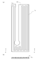
- FIG. 4A is a plan view showing a left cooling plate
- FIG. 6A is a plan view showing the right cooling plate, and FIG.
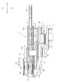
- the left front perspective view of the conveyance apparatus which concerns on 2nd embodiment.
- the front view of the conveying apparatus which concerns on 2nd embodiment.
- the left view of the conveying apparatus which concerns on 2nd embodiment.
- FIG. 4A is a plan view showing a lower cooling plate
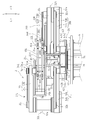
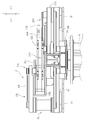
- FIG. 1 the overall configuration of the transport apparatus 100 will be described with reference to FIGS. 1 to 5.
- the arrow A direction is the front, and the directions indicated by the arrow directions in FIG.
- the transfer device 100 includes a link arm mechanism 2 for transferring a workpiece 200 in a vacuum space, and a swing shaft 3 that rotatably supports the link arm mechanism 2 around a vertical axis. And comprising.
- the lower part of the pivot shaft 3 is fixed to the housing 4.
- a link arm mechanism 2 is provided at the upper part.
- a drive unit (not shown) is provided inside the turning shaft 3, and by driving the drive unit, the lower left arm 31L and the lower right arm 31R of the link arm mechanism 2 rotate. Further, by rotating the turning shaft 3, the entire link arm mechanism 2 can be rotated around the vertical axis.
- the turning shaft 3 can slide in the vertical direction with respect to the housing 4, and the turning shaft 3 and the link arm mechanism 2 can be slid in the vertical direction.
- a space above the boundary between the lower surface of the pivot shaft 3 and the upper surface of the housing is a vacuum space for transporting the workpiece 200.
- the link arm mechanism 2 is a mechanism that horizontally moves the workpiece 200.
- the workpiece 200 is, for example, a substrate or a liquid crystal panel, and is formed in a plate shape.
- the link arm mechanism 2 includes a turning base 20, left and right link arms 21L and 21R, and left and right horizontal moving members 22L and 22R.
- the left link arm 21L includes a lower left arm 31L, a left intermediate link 32L, an upper left arm 33L, and a left horizontal movement member connecting portion 34L.
- the right link arm includes 21R, a lower right arm 31R, a right intermediate link 32R, an upper right arm 33R, and a right horizontal moving member connecting portion 34R. Note that the configuration of the left and right link arms 21L and 21R is not limited, and may be configured to be opposite to the left and right.
- the turning base 20 is connected to the upper part of the turning shaft 3.
- the turning shaft 3 includes a bottom plate 41, a left link arm rotation shaft portion 42, a right link arm rotation shaft portion 43, and a front apron portion 44.
- the bottom plate 41 is a plate-like member and is connected to the pivot shaft 3 so as not to be relatively rotatable.
- the left link arm rotation shaft portion 42 is a portion serving as a rotation center of the left link arm 21L, and includes a drive shaft 42a and a driven shaft 42b.
- a drive shaft of a drive unit (not shown) is connected to the drive shaft 42a.
- the right link arm rotation shaft portion 43 is a portion serving as a rotation center of the right link arm 21R, and includes a drive shaft 43a and a driven shaft 43b.
- a drive shaft of a drive unit (not shown) is connected to the drive shaft 43a.
- the lower right arm 32R rotates about the right link arm rotation shaft portion 43 as a rotation center.
- a drive shaft 42 a and a drive shaft 43 a are provided on the upper surface of the bottom plate 41.
- the drive shaft 42 a and the drive shaft 43 a are disposed at positions shifted from the rotation axis of the turning shaft 3.
- a front apron portion 44 is fixed to the front surface of the bottom plate 41.
- the front apron portion 44 is a substantially bowl-shaped member in side view, and a lower end thereof is fixed to the front surface of the bottom plate 41.
- the lower left arm 31L includes a first arm member 51L and a second arm member 52L which are a pair of long plate members.
- a parallel link mechanism is configured between the lower left arm 31L, the left link arm rotation shaft portion 42, and the left intermediate link 32L.
- the base end portion of the first arm member 51L is coupled to the drive shaft 42a of the left link arm rotation shaft portion 42 so as not to be relatively rotatable.
- the base end portion of the second arm member 52L is rotatably connected to the driven shaft 42b.
- the lower left arm 31L pivots around the left link arm pivot shaft 42 as a pivot center.
- the other end of the first arm member 51L is connected to an interlocking shaft 32a provided on the left intermediate link 32L so as not to be relatively rotatable.
- the other end of the second arm member 52L is rotatably connected to a rotation shaft 32b provided on the left intermediate link 32L.
- the left intermediate link 32L is a member that connects the lower left arm 31L and the upper left arm 33L, and rotates the upper left arm 33L in conjunction with the movement of the lower left arm 31L.
- the left intermediate link 32L includes an interlocking shaft 32a and rotating shafts 32b and 32c.
- the interlocking shaft 32a is provided with an interlocking mechanism (not shown) inside.
- the upper left arm 33L includes a third arm member 53L and a fourth arm member 54L which are a pair of long plate members.
- a parallel link mechanism is configured between the upper left arm 33L, the left intermediate link 32L, and the left horizontal moving member connecting portion 34L.
- the base end portion of the third arm member 53L is connected to the interlocking shaft 32a of the left intermediate link 32L so as not to be relatively rotatable.
- the base end portion of the fourth arm member 54L is rotatably connected to the rotation shaft 32c of the left intermediate link 32L. Thereby, the third arm member 53L is rotated in conjunction with the movement of the first arm member 51L via the interlocking mechanism (not shown) of the interlocking shaft 32a.
- the other end portion of the third arm member 53L is connected to a support shaft 34a provided in the left horizontal movement member connecting portion 34L so as not to be relatively rotatable.
- the other end portion of the fourth arm member 54L is rotatably connected to a rotation shaft 34b provided in the left horizontal movement member connection portion 34L.
- the left horizontal movement member 22L has a horizontal movement base 65L and a claw 66L.
- the horizontal movement base 65L is connected to the lower side of the support shaft 34a of the left horizontal movement member connecting portion 34L and to the lower side of the third arm member 53R.
- the horizontal movement base 65L is formed in a plate shape, and two claws 66L and 66L project from the front end thereof.
- the claws 66L and 66L are thin plate-like members, and the workpiece 200 can be placed on the upper surface thereof.
- the left horizontal movement member 22L can be horizontally moved in the front-rear direction by performing a link operation such that the lower left arm 31L and the upper left arm 33L extend and contract.
- the lower right arm 31R includes a first arm member 51R and a second arm member 52R which are a pair of long plate members.
- a parallel link mechanism is configured among the lower right arm 31R, the right link arm rotation shaft portion 43, and the right intermediate link 32R.
- the base end portion of the first arm member 51 ⁇ / b> R is coupled to the drive shaft 43 a of the right link arm rotation shaft portion 43 so as not to be relatively rotatable.
- the base end portion of the second arm member 52R is rotatably connected to the driven shaft 43b. As a result, the lower right arm 31R pivots about the right link arm pivot shaft 43 as a pivot center.
- the other end of the first arm member 51R is connected to an interlocking shaft 32a provided on the right intermediate link 32R so as not to be relatively rotatable.
- the other end of the second arm member 52R is rotatably connected to a rotation shaft 32b provided on the right intermediate link 32R.
- the right intermediate link 32R is a member that connects the lower right arm 31R and the upper right arm 33R, and rotates the upper right arm 33R in conjunction with the movement of the lower right arm 31R.
- the right intermediate link 32R includes an interlocking shaft 32a and rotating shafts 32b and 32c.
- the interlocking shaft 32a is provided with an interlocking mechanism (not shown) inside. Further, the interlocking shaft 32a of the right intermediate link 32R is formed to have a shorter vertical length than the interlocking shaft 32a of the left intermediate link 32L.
- the upper right arm 33R, the right horizontal moving member connecting portion 34R, and the right horizontal moving member 22R are positioned lower than the upper left arm 33L, the left horizontal moving member connecting portion 34L, and the left horizontal moving member 22L, respectively. Be placed.
- the upper right arm 33R includes a third arm member 53R and a fourth arm member 54R, which are a pair of long plate members.
- a parallel link mechanism is configured between the upper right arm 33R, the right intermediate link 32R, and the right horizontal moving member connecting portion 34R.
- the base end portion of the third arm member 53R is connected to the interlocking shaft 32a of the right intermediate link 32R so as not to be relatively rotatable.
- the base end portion of the fourth arm member 54R is rotatably connected to the rotation shaft 32c of the right intermediate link 32R.
- the third arm member 53R is rotated in conjunction with the movement of the first arm member 51R via the interlocking mechanism (not shown) of the interlocking shaft 32.
- the other end portion of the third arm member 53R is connected to a support shaft 34a provided in the right horizontal moving member connecting portion 34R so as not to be relatively rotatable.
- the other end portion of the fourth arm member 54R is rotatably connected to a rotation shaft 34b provided in the right horizontal movement member connection portion 34R.
- the right horizontal movement member 22R has a horizontal movement base 65R and a claw 66R.
- the horizontal movement base 65R is connected to the upper side of the support shaft 34a of the right horizontal movement member connecting portion 34R and to the upper side of the third arm member 53R.
- the horizontal movement base 65R is formed in a plate shape, and two left and right claws 66R and 66R project from the front end thereof.
- the claws 66R and 66R are thin plate-like members, and the workpiece 200 can be placed on the upper surface thereof.
- the left and right horizontal moving members 22L and 22R are configured to overlap each other with a predetermined interval without coming into contact with each other because the positions in the vertical direction are different.
- the cooling plates 25L and 25R include a left cooling plate 25L and a right cooling plate 25R respectively corresponding to the left and right link arms 21L and 21R.
- the left cooling plate 25L is a plate-like member, and is a color member that easily absorbs heat such as black.
- the left cooling plate 25 ⁇ / b> L is provided with a refrigerant passage 71 on the surface thereof.
- the refrigerant passage 71 is fitted into a groove provided on the surface of the left cooling plate 25L.
- the left cooling plate 25L is arranged such that the refrigerant passage 71 is located on the upper surface.
- the refrigerant passage 71 is disposed so as to be bent in a zigzag shape and cool the entire surface of the left cooling plate 25L.
- the refrigerant flowing through the refrigerant passage 71 is composed of water, oil, or the like.
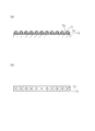
- the refrigerant passage 71 can be attached to the surface of the left cooling plate 25L by a fixture 72.
- a space surrounded by the surface of the left cooling plate 25L, the outer peripheral surface of the refrigerant passage 71, and the inner peripheral surface of the fixture 72 is filled with a filler 73 for increasing the heat transfer coefficient.
- the refrigerant passage 71 and the fixture 72 are arranged so as to be bent in a zigzag shape to cool the entire surface of the left cooling plate 25L.
- the refrigerant passage 71 can be provided inside the left cooling plate 25L.
- the refrigerant passage 71 is arranged so as to be bent in a zigzag shape to cool the entire surface of the left cooling plate 25L.
- the left cooling plate 25L is disposed below the third arm member 53L and the fourth arm member 54L and above the horizontal movement base 65L. That is, the left cooling plate 25L is provided between the surface of the upper left arm 33L on the left horizontal moving member 22L side and the left horizontal moving member 22L. Further, the left cooling plate 25L has an area including the entire moving range in plan view of the upper left arm 33L. Further, as shown in FIGS. 4 and 6, a support shaft passage groove 25 a having a width slightly larger than the radius of the support shaft 34 a is provided on the front side of the left cooling plate 25 ⁇ / b> L in the left and right direction in plan view. The interlocking shaft passage groove 25a is provided in a range that does not prevent the support shaft 34a from moving in the front-rear direction when the horizontal moving member 22L moves in the front-rear direction.
- the right cooling plate 25R is a plate-like member, and is a color member that easily absorbs heat such as black. Further, the right cooling plate 25R has the same configuration as the left cooling plate 25L, and as shown in FIG. 8, a refrigerant passage 71 is provided on the surface thereof. The right cooling plate 25R is disposed such that the refrigerant passage 71 is located on the lower surface. The refrigerant passage 71 is arranged so as to be bent in a zigzag manner to cool the entire surface of the right cooling plate 25R.
- the refrigerant flowing through the refrigerant passage 71 is composed of water, oil, or the like.
- the refrigerant passage 71 can be attached to the surface of the right cooling plate 25R by a fixture 72 as shown in FIG. 7A, similarly to the refrigerant passage 71 of the left cooling plate 25L.
- a space surrounded by the surface of the right cooling plate 25R, the outer peripheral surface of the refrigerant passage 71, and the inner peripheral surface of the fixture 72 is filled with a filler 73 for increasing the heat transfer coefficient.
- the refrigerant passage 71 and the fixture 72 are arranged so as to be bent in a zigzag shape to cool the entire surface of the right cooling plate 25R.
- the refrigerant passage 71 can be provided inside the right cooling plate 25R.
- the refrigerant passage 71 is arranged so as to be bent in a zigzag shape to cool the entire right cooling plate 25R.
- the right cooling plate 25R is disposed above the third arm member 53R and below the fourth arm member 54R and the horizontal movement base 65R. That is, the right cooling plate 25R is provided between the surface of the upper right arm 33R on the right horizontal moving member 22R side and the right horizontal moving member 22R. Further, the right cooling plate 25R has an area that includes the entire moving range in plan view of the upper right arm 33R. Further, as shown in FIGS. 4 and 8, a support shaft passage groove 25a having a width slightly larger than the radius of the support shaft 34a is provided on the front side of the right cooling plate 25R rightward in the left-right direction in plan view. The interlocking shaft passage groove 25a is provided in a range that does not prevent the support shaft 34a from moving in the front-rear direction when the horizontal moving member 22L moves in the front-rear direction.
- a first cooling plate support member 75 is provided to protrude rearward and upward from the rear surface of the bottom plate 41 of the turning base 20. From the upper surface of the front apron portion 44, second cooling plate support members 76, 76 made of two columnar members project upward. A third cooling plate support member 77 projects upward from the drive shaft 42 a of the left link arm rotation shaft portion 42.
- the right cooling plate 25R is supported from below by a first cooling plate support member 75, second cooling plate support members 76 and 76, and a third cooling plate support member 77.
- a plurality of left cooling plate support members 78, 78, 78, 78 are erected on the left side surface and the rear surface of the right cooling plate 25R.
- the left cooling plate 25L is fixed to the upper part of the left cooling plate support members 78, 78, 78, 78 and supported from below.
- a reflective material 81 is attached to the lower surface of the left cooling plate 25L. That is, the reflective material 81 is stuck on the surface of the left cooling plate 25L on the left horizontal moving member 22L side.
- the reflective material 81 is attached to the left cooling plate 25L by a plurality of adhesive members 82.
- the reflecting material 81 is formed of a thin metal plate that can reflect radiant heat from the workpiece 200.
- the reflective material 81 of the same structure is stuck on the upper surface of the right cooling plate 25R. That is, the reflective material 81 is stuck on the surface of the right cooling plate 25R on the right horizontal moving member 22R side.
- a lower cooling plate 91 is disposed below the lower left arm 31L and the lower right arm 31R.
- the structure of the conveying apparatus 100 other than the lower side cooling plate 91 is the same structure as the structure of the conveying apparatus 100 shown in 1st embodiment, description is abbreviate
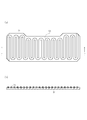
- the lower cooling plate 91 is a plate-like member and is a color member that easily absorbs heat such as black.
- the lower cooling plate 91 is provided on the lower surfaces of the lower left arm 31L and the lower right arm 31R. Further, the lower cooling plate 91 has the same configuration as the left cooling plate 25L, and as shown in FIG. 12, a refrigerant passage 71 is provided on the surface thereof.
- the lower cooling plate 91 is disposed such that the refrigerant passage 71 is located on the upper surface.
- the refrigerant passage 71 is arranged so as to be bent in a zigzag shape and cool the entire surface of the lower cooling plate 91.
- the refrigerant passage 71 can be attached to the surface of the lower cooling plate 91 by a fixture 72 as shown in FIG. 7A, similarly to the refrigerant passage 71 of the left cooling plate 25L.
- a space surrounded by the surface of the lower cooling plate 91, the outer peripheral surface of the refrigerant passage 71, and the inner peripheral surface of the fixture 72 is filled with a filler 73 for increasing the heat transfer coefficient.
- the refrigerant passage 71 and the fixture 72 are arranged so as to be bent in a zigzag shape to cool the entire surface of the lower cooling plate 91.
- the refrigerant passage 71 can also be provided inside the lower cooling plate 91 as shown in FIG.
- the refrigerant passage 71 is arranged so as to be bent in a zigzag shape to cool the entire surface of the lower cooling plate 91.
- the lower cooling plate 91 has an area that includes the entire moving range in plan view of the lower left arm 31L and the lower right arm 31R.
- the lower cooling plate 91 is supported from below by a support member 92 protruding from the rear surface of the bottom plate 41 of the turning base 20.
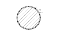
- a turning shaft cooling plate 95 is arranged around the turning shaft 3.
- the structure of the conveying apparatus 100 other than the rotating shaft cooling plate 95 is the same structure as the structure of the conveying apparatus 100 shown in 1st embodiment, description is abbreviate
- Rotating shaft cooling plate 95 is formed in a shape obtained by rounding a long plate into an annular shape.
- the turning shaft cooling plate 95 is a member of a color that easily absorbs heat such as black.
- the turning shaft cooling plate 95 has the same configuration as the left cooling plate 25L, and as shown in FIG. 14, a refrigerant passage 71 is provided on the surface thereof.
- the swivel axis cooling plate 95 is arranged so that the refrigerant passage 71 is located on the inner surface.
- the refrigerant passage 71 is disposed so as to be bent in a zigzag shape and cool the entire inner surface of the turning shaft cooling plate 95.
- the turning shaft cooling plate 95 is attached to the outside of the turning shaft 3.
- the refrigerant passage 71 can also be attached to the surface of the swivel shaft cooling plate 95 by a fixture 72 as shown in FIG. 7A, similarly to the refrigerant passage 71 of the left cooling plate 25L.
- a space surrounded by the surface of the rotating shaft cooling plate 95, the outer peripheral surface of the refrigerant passage 71, and the inner peripheral surface of the fixture 72 is filled with a filler 73 for increasing the heat transfer coefficient.
- the refrigerant passage 71 and the fixture 72 are disposed so as to be bent in a zigzag shape so as to cool the entire inner surface of the turning shaft cooling plate 95.
- the refrigerant passage 71 may be provided inside the turning shaft cooling plate 95 as shown in FIG.
- the refrigerant passage 71 is disposed so as to be bent in a zigzag shape and cool the entire surface of the turning shaft cooling plate 95.
- the transport apparatus 100 includes the link arm mechanism 2 for transporting the workpiece 200 in the vacuum space and the pivot shaft 3 that pivotally supports the link arm mechanism 2 so as to be rotatable about the vertical axis.
- the link arm mechanism 2 supports the lower arm 31L / 31R, the upper arm 33L / 33R coupled to the lower arm 31L / 31R, and the workpiece 200 coupled to the other end of the upper arm 33L / 33R.
- Horizontal movement members 22L and 22R, and cooling plates 25L and 25R are disposed between the upper arms 33L and 33R and the horizontal movement members 22L and 22R.
- Reflectors 81 and 81 are attached to the surfaces of the moving members 22L and 22R.
- a cooling plate is interposed between the upper arms 33L and 33R of the link arm mechanism 2 and the workpieces 200 and 200 in a high temperature state.
- the upper arms 33L and 33R can be cooled by the cooling plates 25L and 25R.
- the left cooling plate 25L is disposed between the lower surface of the upper left arm 33L and the workpiece 200 placed on the left horizontal moving member 22L, thereby cooling the upper left arm 33L with the left cooling plate 25L. can do.
- the right cooling plate 25R is disposed between the upper surface of the upper right arm 33R, in particular, the upper surface of the third arm 53R and the workpiece 200 placed on the right horizontal moving member 22R, so that the upper right arm 33R is moved to the right. It can be cooled by the cooling plate 25R. Therefore, the influence of radiant heat from the workpiece 200 in a high temperature state can be reduced. Moreover, by comprising in this way, the radiant heat from the workpiece
- the conveying apparatus 100 arrange
- the transport device 100 is obtained by winding a turning shaft cooling plate 95 around the turning shaft 3.
- the turning shaft 3 that supports the link arm mechanism 2 can be cooled by the turning shaft cooling plate 95. Therefore, the influence of radiant heat from the workpiece 200 in a high temperature state can be reduced.
- the present invention can be used in a transfer device for transferring a substrate in a vacuum space.
Landscapes
- Engineering & Computer Science (AREA)
- Robotics (AREA)
- Mechanical Engineering (AREA)
- Manipulator (AREA)
- Container, Conveyance, Adherence, Positioning, Of Wafer (AREA)
Priority Applications (3)
| Application Number | Priority Date | Filing Date | Title |
|---|---|---|---|
| US13/884,117 US9259841B2 (en) | 2010-11-08 | 2011-11-02 | Carrier device |
| US14/990,324 US9566713B2 (en) | 2010-11-08 | 2016-01-07 | Carrier device |
| US15/398,187 US9868206B2 (en) | 2010-11-08 | 2017-01-04 | Carrier device |
Applications Claiming Priority (2)
| Application Number | Priority Date | Filing Date | Title |
|---|---|---|---|
| JP2010-249606 | 2010-11-08 | ||
| JP2010249606A JP5606279B2 (ja) | 2010-11-08 | 2010-11-08 | 搬送装置 |
Related Child Applications (2)
| Application Number | Title | Priority Date | Filing Date |
|---|---|---|---|
| US13/884,117 A-371-Of-International US9259841B2 (en) | 2010-11-08 | 2011-11-02 | Carrier device |
| US14/990,324 Division US9566713B2 (en) | 2010-11-08 | 2016-01-07 | Carrier device |
Publications (1)
| Publication Number | Publication Date |
|---|---|
| WO2012063706A1 true WO2012063706A1 (ja) | 2012-05-18 |
Family
ID=46050855
Family Applications (1)
| Application Number | Title | Priority Date | Filing Date |
|---|---|---|---|
| PCT/JP2011/075312 Ceased WO2012063706A1 (ja) | 2010-11-08 | 2011-11-02 | 搬送装置 |
Country Status (3)
| Country | Link |
|---|---|
| US (3) | US9259841B2 (https=) |
| JP (1) | JP5606279B2 (https=) |
| WO (1) | WO2012063706A1 (https=) |
Cited By (1)
| Publication number | Priority date | Publication date | Assignee | Title |
|---|---|---|---|---|
| JP2022184739A (ja) * | 2021-05-31 | 2022-12-13 | 株式会社ティーロボティクス | 真空チャンバで基板を移送するための基板移送ロボット |
Families Citing this family (7)
| Publication number | Priority date | Publication date | Assignee | Title |
|---|---|---|---|---|
| JP5606279B2 (ja) * | 2010-11-08 | 2014-10-15 | 株式会社ダイヘン | 搬送装置 |
| US20130272822A1 (en) * | 2011-12-19 | 2013-10-17 | Kabushiki Kaisha Yaskawa Denki | Transfer robot |
| KR102402324B1 (ko) * | 2014-01-28 | 2022-05-26 | 브룩스 오토메이션 인코퍼레이티드 | 기판 이송 장치 |
| JP6339057B2 (ja) * | 2015-09-29 | 2018-06-06 | 株式会社日立国際電気 | 基板処理装置、半導体装置の製造方法、プログラム |
| US10109517B1 (en) * | 2018-01-10 | 2018-10-23 | Lam Research Corporation | Rotational indexer with additional rotational axes |
| KR102240925B1 (ko) * | 2019-07-17 | 2021-04-15 | 세메스 주식회사 | 기판 처리 설비 및 기판 반송 장치 |
| KR102431664B1 (ko) * | 2022-02-15 | 2022-08-12 | (주) 티로보틱스 | 진공 챔버에서 기판을 이송하기 위한 기판 이송 로봇 |
Citations (3)
| Publication number | Priority date | Publication date | Assignee | Title |
|---|---|---|---|---|
| JPH1187463A (ja) * | 1997-09-12 | 1999-03-30 | Dainippon Screen Mfg Co Ltd | 基板処理装置 |
| JP2001035902A (ja) * | 1999-07-26 | 2001-02-09 | Jel:Kk | 基板搬送用ロボット |
| WO2006062183A1 (ja) * | 2004-12-10 | 2006-06-15 | Ulvac, Inc. | 搬送ロボット及び搬送装置 |
Family Cites Families (7)
| Publication number | Priority date | Publication date | Assignee | Title |
|---|---|---|---|---|
| JPH06204316A (ja) * | 1992-12-28 | 1994-07-22 | Mitsubishi Electric Corp | 耐熱ロボットハンド |
| US6499777B1 (en) * | 1999-05-11 | 2002-12-31 | Matrix Integrated Systems, Inc. | End-effector with integrated cooling mechanism |
| JP4908306B2 (ja) * | 2007-05-10 | 2012-04-04 | 株式会社ダイヘン | 搬送装置 |
| JP5189833B2 (ja) | 2007-12-19 | 2013-04-24 | 株式会社ダイヘン | 真空搬送装置 |
| JP2010177411A (ja) | 2009-01-29 | 2010-08-12 | Daihen Corp | ワーク搬送装置 |
| KR20120127463A (ko) * | 2010-01-22 | 2012-11-21 | 어플라이드 머티어리얼스, 인코포레이티드 | 기판 냉각을 수반하는 이송 로봇 |
| JP5606279B2 (ja) * | 2010-11-08 | 2014-10-15 | 株式会社ダイヘン | 搬送装置 |
-
2010
- 2010-11-08 JP JP2010249606A patent/JP5606279B2/ja active Active
-
2011
- 2011-11-02 US US13/884,117 patent/US9259841B2/en active Active
- 2011-11-02 WO PCT/JP2011/075312 patent/WO2012063706A1/ja not_active Ceased
-
2016
- 2016-01-07 US US14/990,324 patent/US9566713B2/en active Active
-
2017
- 2017-01-04 US US15/398,187 patent/US9868206B2/en not_active Expired - Fee Related
Patent Citations (3)
| Publication number | Priority date | Publication date | Assignee | Title |
|---|---|---|---|---|
| JPH1187463A (ja) * | 1997-09-12 | 1999-03-30 | Dainippon Screen Mfg Co Ltd | 基板処理装置 |
| JP2001035902A (ja) * | 1999-07-26 | 2001-02-09 | Jel:Kk | 基板搬送用ロボット |
| WO2006062183A1 (ja) * | 2004-12-10 | 2006-06-15 | Ulvac, Inc. | 搬送ロボット及び搬送装置 |
Cited By (2)
| Publication number | Priority date | Publication date | Assignee | Title |
|---|---|---|---|---|
| JP2022184739A (ja) * | 2021-05-31 | 2022-12-13 | 株式会社ティーロボティクス | 真空チャンバで基板を移送するための基板移送ロボット |
| JP7381125B2 (ja) | 2021-05-31 | 2023-11-15 | 株式会社ティーロボティクス | 真空チャンバで基板を移送するための基板移送ロボット |
Also Published As
| Publication number | Publication date |
|---|---|
| US9259841B2 (en) | 2016-02-16 |
| US20130294870A1 (en) | 2013-11-07 |
| JP5606279B2 (ja) | 2014-10-15 |
| US20160121485A1 (en) | 2016-05-05 |
| US20170113345A1 (en) | 2017-04-27 |
| JP2012101292A (ja) | 2012-05-31 |
| US9566713B2 (en) | 2017-02-14 |
| US9868206B2 (en) | 2018-01-16 |
Similar Documents
| Publication | Publication Date | Title |
|---|---|---|
| JP5606279B2 (ja) | 搬送装置 | |
| JP2012101292A5 (https=) | ||
| TWI558522B (zh) | Industrial robots | |
| WO2021022622A1 (zh) | 一种转向装置、传输模块、自动码垛传送系统和自动码垛传送方法 | |
| JP2008279538A (ja) | 搬送装置 | |
| JP6606319B2 (ja) | 産業用ロボット | |
| CN217436975U (zh) | 一种输送线电池模组翻转机构 | |
| JP2008094546A (ja) | ベルトコンベヤ蛇行修正装置 | |
| KR20130071344A (ko) | 반송 로봇 | |
| CN203889594U (zh) | 分拣和输送系统 | |
| KR101511179B1 (ko) | 성막장치, 및 성막장치용 반송트레이 | |
| JP5403378B2 (ja) | ロボットハンド及びロボット | |
| CN120300046A (zh) | 高精度多规格芯片上料设备 | |
| CN208728927U (zh) | 双头双面激光打标机 | |
| WO2019065204A1 (ja) | 搬送システム | |
| CN100519095C (zh) | 搬送装置 | |
| JP2015044638A (ja) | ワーク搬送装置 | |
| JP6902422B2 (ja) | 産業用ロボット | |
| JP4284118B2 (ja) | 基板搬送装置 | |
| JP7221651B2 (ja) | 搬送車 | |
| JP2003192114A (ja) | ベルト自動調心装置 | |
| CN219427926U (zh) | 移动机器人的驱动装置和底盘以及移动机器人 | |
| CN215260196U (zh) | 传动装置和空调室外机 | |
| CN216511030U (zh) | 一种冷链运输用检测监控设备 | |
| JP2013084823A (ja) | 搬送ロボット及び真空装置 |
Legal Events
| Date | Code | Title | Description |
|---|---|---|---|
| 121 | Ep: the epo has been informed by wipo that ep was designated in this application |
Ref document number: 11839031 Country of ref document: EP Kind code of ref document: A1 |
|
| DPE1 | Request for preliminary examination filed after expiration of 19th month from priority date (pct application filed from 20040101) | ||
| NENP | Non-entry into the national phase |
Ref country code: DE |
|
| WWE | Wipo information: entry into national phase |
Ref document number: 13884117 Country of ref document: US |
|
| 122 | Ep: pct application non-entry in european phase |
Ref document number: 11839031 Country of ref document: EP Kind code of ref document: A1 |