WO2012063420A1 - 超音波診断装置および超音波診断システム - Google Patents
超音波診断装置および超音波診断システム Download PDFInfo
- Publication number
- WO2012063420A1 WO2012063420A1 PCT/JP2011/006009 JP2011006009W WO2012063420A1 WO 2012063420 A1 WO2012063420 A1 WO 2012063420A1 JP 2011006009 W JP2011006009 W JP 2011006009W WO 2012063420 A1 WO2012063420 A1 WO 2012063420A1
- Authority
- WO
- WIPO (PCT)
- Prior art keywords
- image
- diagnostic
- probe
- ultrasonic
- angle
- Prior art date
Links
Images


Classifications
-
- A—HUMAN NECESSITIES
- A61—MEDICAL OR VETERINARY SCIENCE; HYGIENE
- A61B—DIAGNOSIS; SURGERY; IDENTIFICATION
- A61B8/00—Diagnosis using ultrasonic, sonic or infrasonic waves
- A61B8/42—Details of probe positioning or probe attachment to the patient
- A61B8/4245—Details of probe positioning or probe attachment to the patient involving determining the position of the probe, e.g. with respect to an external reference frame or to the patient
- A61B8/4254—Details of probe positioning or probe attachment to the patient involving determining the position of the probe, e.g. with respect to an external reference frame or to the patient using sensors mounted on the probe
-
- A—HUMAN NECESSITIES
- A61—MEDICAL OR VETERINARY SCIENCE; HYGIENE
- A61B—DIAGNOSIS; SURGERY; IDENTIFICATION
- A61B8/00—Diagnosis using ultrasonic, sonic or infrasonic waves
- A61B8/08—Detecting organic movements or changes, e.g. tumours, cysts, swellings
- A61B8/0891—Detecting organic movements or changes, e.g. tumours, cysts, swellings for diagnosis of blood vessels
-
- A—HUMAN NECESSITIES
- A61—MEDICAL OR VETERINARY SCIENCE; HYGIENE
- A61B—DIAGNOSIS; SURGERY; IDENTIFICATION
- A61B8/00—Diagnosis using ultrasonic, sonic or infrasonic waves
- A61B8/40—Positioning of patients, e.g. means for holding or immobilising parts of the patient's body
-
- A—HUMAN NECESSITIES
- A61—MEDICAL OR VETERINARY SCIENCE; HYGIENE
- A61B—DIAGNOSIS; SURGERY; IDENTIFICATION
- A61B8/00—Diagnosis using ultrasonic, sonic or infrasonic waves
- A61B8/46—Ultrasonic, sonic or infrasonic diagnostic devices with special arrangements for interfacing with the operator or the patient
- A61B8/461—Displaying means of special interest
- A61B8/463—Displaying means of special interest characterised by displaying multiple images or images and diagnostic data on one display
-
- A—HUMAN NECESSITIES
- A61—MEDICAL OR VETERINARY SCIENCE; HYGIENE
- A61B—DIAGNOSIS; SURGERY; IDENTIFICATION
- A61B8/00—Diagnosis using ultrasonic, sonic or infrasonic waves
- A61B8/46—Ultrasonic, sonic or infrasonic diagnostic devices with special arrangements for interfacing with the operator or the patient
- A61B8/467—Ultrasonic, sonic or infrasonic diagnostic devices with special arrangements for interfacing with the operator or the patient characterised by special input means
-
- A—HUMAN NECESSITIES
- A61—MEDICAL OR VETERINARY SCIENCE; HYGIENE
- A61B—DIAGNOSIS; SURGERY; IDENTIFICATION
- A61B8/00—Diagnosis using ultrasonic, sonic or infrasonic waves
- A61B8/52—Devices using data or image processing specially adapted for diagnosis using ultrasonic, sonic or infrasonic waves
- A61B8/5292—Devices using data or image processing specially adapted for diagnosis using ultrasonic, sonic or infrasonic waves using additional data, e.g. patient information, image labeling, acquisition parameters
-
- A—HUMAN NECESSITIES
- A61—MEDICAL OR VETERINARY SCIENCE; HYGIENE
- A61B—DIAGNOSIS; SURGERY; IDENTIFICATION
- A61B8/00—Diagnosis using ultrasonic, sonic or infrasonic waves
- A61B8/46—Ultrasonic, sonic or infrasonic diagnostic devices with special arrangements for interfacing with the operator or the patient
- A61B8/461—Displaying means of special interest
- A61B8/465—Displaying means of special interest adapted to display user selection data, e.g. icons or menus
Definitions
- the present invention relates to an ultrasonic diagnostic apparatus having a function of displaying an angle of an ultrasonic probe when a subject is being diagnosed.
- An ultrasonic diagnostic apparatus is a medical imaging apparatus that obtains a tomographic image (diagnostic image) of a soft tissue based on reflected waves from each tissue in the body by irradiating the subject with ultrasonic waves. Widely used.
- the angle of the ultrasonic probe when obtaining the diagnostic image is the same as the angle of the ultrasonic probe when obtaining the current diagnostic image. It is desirable that the angle adjustment of the ultrasonic probe can be easily performed in a short time.
- an ultrasonic diagnostic apparatus that performs guidance display so that the current position and orientation of the probe can be matched with the position and orientation of the probe at the time of past diagnosis (see, for example, Patent Document 1). ).
- the spatial position and orientation of the probe are measured using a magnetic sensor provided in the probe and a magnetic generator installed in a bed, etc., and measurement data at the time of past diagnosis
- the registered probe mark is displayed based on the current coordinate data
- the current probe mark is displayed based on the current coordinate data
- the proximity and coincidence between the registered coordinate and the current coordinate are displayed in the guidance display.
- An object of the present invention is to provide an ultrasonic diagnostic apparatus capable of obtaining and displaying the angle of an ultrasonic probe when diagnosing a subject without the need to install a large-scale apparatus as in the prior art. There is.
- an ultrasonic diagnostic apparatus is provided with an ultrasonic probe and relative to the direction of gravity of the ultrasonic probe provided in the ultrasonic probe and diagnosing a subject.
- a sensor that outputs sensor information for obtaining an angle
- an angle conversion unit that converts the sensor information into angle information of the ultrasonic probe
- a display processing unit that displays the angle information on the display unit.
- FIG. 1 is a block diagram of an ultrasonic diagnostic apparatus according to the first embodiment of the present invention.
- FIG. 2 is an explanatory diagram of a display screen at the time of IMT measurement.
- Fig. 3 is an explanatory diagram of the display screen during plaque search.
- 4 is an explanatory diagram of the workflow button.
- FIG. 5 is an explanatory diagram of a guide image
- FIG. 6 is an explanatory diagram of a guide image and a workflow button (flashing state).
- FIG. 7 is an explanatory diagram of a reference probe image.
- FIG. 8 is an explanatory diagram of an animation image
- FIG. 9 is a block diagram of an ultrasonic diagnostic apparatus according to the second embodiment of the present invention.
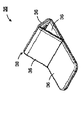
- FIG. 10 is a perspective view of a folding pillow (in use).
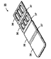
- FIG. 11 is a perspective view of a folding pillow (stored state).
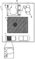
- FIG. 12 is a schematic explanatory diagram of the usage state of the folding pillow.
- the ultrasonic diagnostic apparatus of the present invention outputs ultrasonic sensor and sensor information that is provided on the ultrasonic probe and determines the relative angle of the ultrasonic probe with respect to the direction of gravity when diagnosing the subject.
- the sensor includes a sensor, an angle conversion unit that converts the sensor information into angle information of the ultrasonic probe, and a display processing unit that displays the angle information on the display unit.
- the display processing unit may have a configuration in which the angle information is displayed on the display unit as a relative angle of the ultrasonic probe with respect to the subject.
- a probe image that represents the ultrasonic probe as a schematic figure and a subject image that represents the subject as a schematic figure are generated, but includes an image generation unit, and the display processing unit
- the probe image may be displayed on the display unit, and the probe image may be arranged at an angle corresponding to the angle information in a region having a predetermined positional relationship with the subject image.
- the display processing unit may have a configuration for displaying an angle corresponding to the angle information depending on the direction of the probe image.
- the display processing unit may have a configuration in which this region is set on the subject image and the probe image is displayed on the display unit so as to be in contact with the subject image.
- a configuration may be provided that includes a diagnostic mode selection unit that selects a diagnostic mode when diagnosing a subject with an ultrasonic probe.
- the sensor information output from the sensor provided in the ultrasonic probe provided in the ultrasonic probe is converted into angle information, so that a conventional large-scale device (for example, provided in the probe)
- the angle of the ultrasonic probe when diagnosing the subject can be obtained and displayed on the display unit without requiring a magnetic field generator that cannot be installed only on the bed.
- the display unit on which the diagnostic image is displayed includes a subject image (body mark) corresponding to the diagnostic mode selected by the user (such as a doctor or a technician), and angle information for the subject image. Since probe images (probe icons) arranged at different angles are displayed, the user can sufficiently obtain information necessary for diagnosis from these images (images displayed on the display unit).
- the senor is an acceleration sensor, and outputs the acceleration information of the ultrasonic probe as information for obtaining the angle of the ultrasonic probe, and the angle conversion unit converts the acceleration information, You may have the structure converted into the angle information of an ultrasonic probe.
- the angle of the ultrasound probe when diagnosing the subject can be obtained by converting the acceleration information output from the acceleration sensor provided in the ultrasound probe into angle information.
- the acceleration sensor does not require a conventional large-scale device (for example, a magnetic field generator that cannot be installed on the probe and can only be installed on the bed), and is easy to miniaturize. Suitable for installation.
- the display processing unit may have a configuration in which a button image whose button name is changed in order according to the diagnostic procedure of the subject is displayed on the display unit.
- the button image (workflow button) displayed on the display unit is changed in order according to the diagnosis procedure of the subject, so the user can use one button (workflow button)
- the diagnostic procedure can be easily and appropriately advanced.
- the display processing unit is configured to display a button image indicating the next diagnostic procedure in a blinking state on the display unit when the diagnostic procedure indicated by the button name is completed. You may have.
- the button (workflow button) is changed to indicate the next diagnostic procedure and blinked. This can prompt the user to proceed to the next diagnostic procedure.
- the ultrasonic diagnostic apparatus of the present invention is obtained in the diagnostic mode before the transition when the storage unit storing the image data of the diagnostic image of the subject and the diagnostic mode of the subject transits to the next diagnostic mode.
- a storage processing unit that associates the image data of the diagnostic image and the angle information that are stored in the storage unit may be included.
- the image data of the diagnostic image obtained in the diagnostic mode (diagnostic mode before transition) and the angle information are stored in association with each other. Therefore, for example, when diagnosing the progress of a diagnostic site, when attempting to refer to a past diagnostic image (diagnostic image obtained in the diagnostic mode), the angle information when the diagnostic image is obtained is also included. And can be compared and observed using images obtained under the same conditions (in the same diagnostic mode and at the same angle).
- the display processing unit displays a reference probe image displayed at an angle according to past angle information read from the storage unit when displaying the probe image on the display unit. You may have the structure displayed separately from a probe image.
- the reference probe icon when the current probe image (probe icon) is displayed, if the diagnosis has been performed in the same diagnostic mode in the past, the reference probe when the diagnostic image is obtained in the past diagnosis An image (reference probe icon) is displayed together.
- the reference probe image (reference probe icon) and the current probe image (probe icon) are displayed in different modes (different colors, shapes, etc.), the user can easily distinguish between them. can do.
- the user matches the reference probe image (reference probe icon) with the current probe image (probe icon), so that the same conditions as the past diagnosis (in the same diagnosis mode and at the same angle). Diagnose with.
- the display processing unit is configured such that when the past angle information is not stored in the storage unit, the reference probe is displayed on the display unit at a recommended angle preset according to the diagnostic mode. You may have the structure which displays an image.
- a recommended angle preset in accordance with the diagnostic mode an appropriate angle according to the diagnostic mode
- a reference probe image reference probe icon
- the display processing unit causes the display unit to display a guide image indicating the direction in which the ultrasonic probe should be tilted in the diagnostic mode, and the guide image is stored in the storage unit in the past angle information. Is generated based on the past angle information read from the storage unit and the current angle information converted from the sensor information, and when the past angle information is not stored in the storage unit
- the configuration may be such that the recommended angle is set based on the diagnosis mode and the current angle information converted from the sensor information is generated.
- a guide image indicating the direction in which the ultrasonic probe should be tilted in the diagnostic mode is displayed on the display unit.
- the guide image is appropriately generated based on the past angle information and the current angle information. Therefore, the user can easily make a diagnosis according to the guide image under the same conditions as the past diagnosis (in the same diagnosis mode and at the same angle).
- the guide image has a recommended angle (appropriate angle according to the diagnosis mode) set in advance according to the diagnosis mode and current angle information. Based on the above, it is generated appropriately. Therefore, the user can easily make a diagnosis under appropriate conditions according to the diagnosis mode according to the guide image.
- the display processing unit displays an animation image for guiding the diagnostic procedure of the subject in the diagnostic mode on the display unit, and the diagnostic procedure guided by the animation image is completed.
- an animation image for guiding the next diagnostic procedure may be displayed.
- an animation image for guiding the diagnosis procedure of the subject is displayed on the display unit.
- an animation image for guiding the next diagnosis procedure is displayed. The user can easily and appropriately proceed with the diagnosis procedure according to the animation image.
- the display processing unit displays the past diagnostic image stored in the storage unit on the display unit
- the past angle information stored in association with the past diagnostic image is stored. May be displayed.
- the ultrasonic diagnostic apparatus of the present invention includes a diagnostic mode determination unit that determines a diagnostic mode when a diagnostic image is obtained by performing image analysis on the diagnostic image, and the display processing unit includes You may have the structure which displays the probe image according to the diagnostic mode determined by the mode determination part.
- a diagnostic mode when the diagnostic image is obtained is automatically determined by image analysis of the diagnostic image, and an appropriate probe image (probe icon) corresponding to the diagnostic mode is displayed on the display unit. Is displayed. For example, if the diagnostic mode is determined to be “plaque search” as a result of image analysis of the diagnostic image, a probe image (probe icon) for performing “plaque search” is displayed. Further, as a result of image analysis of the diagnostic image, if it is determined that the diagnostic mode is “IMT (Intima-Media Thickness) measurement”, a probe for performing “IMT measurement” An image (probe icon) is displayed.
- IMT Intima-Media Thickness
- the ultrasonic diagnostic apparatus of the present invention includes a diagnostic mode determination unit that determines a diagnostic mode when a diagnostic image is obtained by performing image analysis of the diagnostic image, and the storage unit is provided for each diagnostic mode of the subject.
- a storage area for storing image data and angle information of the diagnostic image, and the storage processing unit distributes the image data and angle information of the diagnostic image to the storage area corresponding to the diagnosis mode determined by the diagnosis mode determination unit May be stored.
- the diagnostic mode when the diagnostic image is obtained is automatically determined, and the image data and angle of the diagnostic image are stored in an appropriate storage area according to the diagnostic mode.
- Information is sorted and stored. For example, if the diagnostic mode is determined to be “plaque search” as a result of image analysis of the diagnostic image, the image data and angle information of the diagnostic image are stored in the storage area for “plaque search”. Further, for example, when it is determined that the diagnostic mode is “IMT measurement” as a result of image analysis of the diagnostic image, the image data and angle information of the diagnostic image are stored in the storage area for “IMT measurement”.
- the display unit may be a touch panel, and the selection of the diagnostic mode may be performed by a touch operation on the touch panel.
- This configuration improves the operability when selecting the diagnostic mode because the display unit and the diagnostic mode selection unit are configured as a touch panel.
- An ultrasonic diagnostic system of the present invention includes an ultrasonic probe, a sensor that is provided in the ultrasonic probe, outputs sensor information for obtaining an angle of the ultrasonic probe when diagnosing an object, and sensor information.
- An angle conversion unit that converts the angle information of the ultrasonic probe, a probe image that represents the ultrasonic probe as a schematic figure, and an image generation unit that generates a subject image that represents the subject as a schematic figure
- the subject image and the probe image are displayed on the display unit, the angle information is set as the angle of the ultrasonic probe with respect to the subject, and the probe image is converted into angle information in a region having a predetermined positional relationship with respect to the previous sample image.
- a display processing unit arranged at an appropriate angle.
- the subject can be obtained without the need for a large-scale apparatus (for example, a magnetic field generator that cannot be installed on the probe and can be installed only on the bed) in the same manner as the above apparatus.
- the angle of the ultrasonic probe when diagnosing can be obtained and displayed on the display unit, and the user can sufficiently obtain information necessary for diagnosis from the image displayed on the display unit it can.
- the ultrasonic diagnostic system of the present invention includes an ultrasonic diagnostic apparatus and a server apparatus that is communicably connected to the ultrasonic diagnostic apparatus, and the server apparatus stores image data of a diagnostic image of a subject.
- the ultrasonic diagnostic apparatus associates the image data of the diagnostic image obtained in the diagnostic mode before the transition and the angle information, You may have the structure provided with the memory
- the image data of the diagnostic image obtained in the diagnostic mode (diagnostic mode before transition) and the angle information are associated with each other, and the ultrasonic device To the server device and stored in the storage unit of the server device. Therefore, for example, when the past diagnostic image (diagnostic image obtained in the diagnostic mode) is to be referred to, for example, when the diagnostic site is being observed, the ultrasonic diagnostic device is stored in the storage unit of the server device.
- the angle information when the diagnostic image is obtained can be obtained together, and the images obtained under the same conditions (the same diagnostic mode and the same angle) can be compared and observed.
- the angle of the ultrasonic probe when the subject is diagnosed can be obtained and displayed.
- FIG. 1 is a block diagram showing the configuration of the ultrasonic diagnostic apparatus according to the present embodiment.
- the ultrasonic diagnostic apparatus 1 includes an operation input unit 2, an ultrasonic probe 3, and a monitor 4 (display unit).
- the operation input unit 2 is, for example, an operation console provided with a keyboard, a mouse, operation buttons, a trackball, and the like.
- the operation input unit 2 is used for various information input, command input, parameter information setting change, and the like.
- the ultrasonic probe 3 is an ultrasonic probe that irradiates a subject with ultrasonic pulses from an ultrasonic transducer (not shown), receives reflected ultrasonic waves from each tissue in the body, and converts them into electrical signals. is there.
- the ultrasonic probe 3 is provided with an acceleration sensor 5 that outputs acceleration information (gravity acceleration information) of the ultrasonic probe 3 when the subject is diagnosed.
- acceleration information gravitation acceleration information
- On the monitor 4 a diagnostic image 6 of the subject obtained by the ultrasonic probe 3 is displayed (see FIG. 2 and the like).
- the monitor 4 is composed of a touch panel, and has a function of selecting a diagnostic mode for diagnosing a subject with the ultrasonic probe 3 by a touch operation.
- the diagnosis mode includes “plaque search (right neck)”, “IMT measurement (right neck)”, “plaque search (left neck)”, “IMT measurement (left neck)”, and the like.
- diagnostic mode buttons 7 corresponding to the respective diagnostic modes are displayed at the left end of the display screen of the monitor 4, and a user (doctor, engineer, etc.) can perform these operations by touch operation. One (or more) can be selected.
- plaque search (right neck)”, “IMT measurement (right neck)”, “plaque search (left neck)”, “IMT measurement (left neck)” In order, these diagnostic modes are shifted in order.
- the diagnostic mode may be automatically determined (determined) by analyzing the diagnostic image 6. For example, when a diagnostic image 6 in which a longitudinal section of the carotid artery is visible as shown in FIG. 2 is obtained, it is determined as “IMT measurement”, and as shown in FIG. When the image 6 is obtained, “plaque search” is determined.
- the ultrasonic diagnostic apparatus 1 includes a transmission unit 8 that transmits a transmission signal for irradiating the ultrasonic probe 3 with an ultrasonic pulse, and a reception signal output from the ultrasonic probe 3 (electricity converted from reflected ultrasonic waves).
- a signal processing unit 10 that performs predetermined signal processing on a signal output from the receiving unit 9.
- the ultrasonic diagnostic apparatus 1 uses the acceleration information output from the acceleration sensor 5 of the ultrasonic probe 3 as the angle information of the ultrasonic probe 3 (the three-dimensional angle of the ultrasonic probe 3 when the subject is being diagnosed).
- An angle conversion unit 11 that converts the information into the information
- a display processing unit 12 that performs various processes (described later) for displaying an image on the monitor 4.
- the conversion of the acceleration information into angle information is derived from the angle data of the triaxial acceleration sensor by calculating the angle of each axis direction with respect to the gravitational acceleration direction from the acceleration data of each axis with respect to the gravitational acceleration of the triaxial acceleration sensor.
- the information on the positional relationship between the triaxial acceleration sensor and the ultrasonic probe 3 is added to this and converted into angle information of the ultrasonic probe 3.
- the conversion method of the acceleration information into the angle information may be a mechanism in which a gyro is added to the three-axis acceleration sensor, a six-axis sensor, or the like. In this embodiment, since it is an operation in which an approximate positional relationship between the subject and the probe in each diagnosis mode can be assumed, the three-axis acceleration sensor is used.
- the ultrasonic diagnostic apparatus 1 includes a storage unit 13 composed of a large capacity HDD or memory, and a control unit 14 composed of a CPU, a microcomputer, and the like.
- the storage unit 13 stores image data of the diagnostic image 6 of the subject in association with the angle information.
- the control unit 14 controls the control of each unit of the ultrasonic diagnostic apparatus 1 .
- the control part 14 may be provided with the function of the image analysis of the diagnostic image 6, and diagnostic mode determination.
- storage part 13 may be provided with the memory
- the image data and angle information of the diagnostic image 6 may be automatically distributed and stored in the storage area.
- the display processing unit 12 generates a probe image 15 (probe icon 15) representing the ultrasonic probe 3 as a schematic figure and a subject image 16 (body mark 16) representing the subject as a schematic figure.
- the monitor 4 has a function of displaying the body mark 16 and the probe icon 15 corresponding to the diagnosis mode.
- the body mark 16 is displayed at a predetermined position on the monitor 4, and the probe icon 15 is displayed in a display area 39 having a predetermined positional relationship with the body mark 16.
- the angle calculated with respect to the gravitational acceleration direction of the ultrasonic probe 3 from the angle conversion unit 11 is regarded as the angle of the ultrasonic probe 3 with respect to the subject, and the probe icon 15 is arranged at an angle corresponding to the angle information. To do.
- the angle information is displayed according to the position and direction in which the probe icon 15 is arranged in the display area.
- the display area 39 is set on or near the body mark 16 and the probe icon 15 is displayed on the monitor 4 as if it is in contact with the body mark 16, the angle information of the ultrasonic probe 3 is displayed to the operator.
- the configuration is easy to image.
- the display processing unit 12 may display the body mark 16 and the probe image corresponding to the diagnostic mode selected by the touch operation by the user, and the body mark corresponding to the diagnostic mode determined by the image analysis of the diagnostic image 6. 16 and a probe image may be displayed.
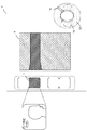
- FIG. 2 is a diagram illustrating an example of a display screen of the monitor 4 at the time of IMT measurement of the right neck.
- a display area 39 is set around the head of the body mark 16.
- the display screen of the monitor 4 shows a body mark 16 corresponding to the diagnostic mode of “IMT measurement (right neck)” (a state in which the neck is tilted to the left when the subject is seen from above the head).
- a probe icon 15 probe icon 15 indicating a state in which the probe is applied sideways along the carotid artery
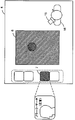
- FIG. 3 is a diagram showing an example of a display screen of the monitor 4 at the time of plaque search for the left neck.
- the display screen of the monitor 4 shows a body mark 16 corresponding to the “plaque search (left neck)” diagnosis mode (the state in which the neck is tilted to the right when the subject is seen from above the head).
- a probe icon 15 (probe icon 15 indicating a state in which the probe is vertically applied to the carotid artery) is displayed according to the diagnosis mode of “plaque search (left neck)”.
- the display processing unit 12 has a function of causing the monitor 4 to display a button image (workflow button 17) whose button names are changed in order according to the diagnostic procedure of the subject.
- FIG. 4 shows an example of the workflow button 17. In the example of FIG. 4, “Freeze” is displayed, but this display is changed in order according to the diagnostic procedure.
- the display of the workflow button 17 is “plaque search (right neck)” “freeze” “IMT measurement (right neck)” “freeze” “plaque search (left neck) ) ”“ Freeze ”“ IMT measurement (left neck) ”“ Freeze ”.
- the workflow button 17 displays the next diagnosis procedure (for example, freeze) on the workflow button 17.
- the workflow button 17 is blinked (see FIG. 6).
- the step can be advanced to the next diagnosis procedure.
- Whether or not the displayed diagnostic image is complete is determined by comparing the diagnostic image acquired in the past or an image stored as a standard image with the diagnostic procedure. Based on this determination, the apparatus is set to proceed to the next diagnostic procedure.
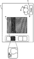
- the display processing unit 12 has a function of causing the monitor 4 to display a guide image 18 indicating the direction in which the ultrasonic probe 3 should be tilted in the diagnosis mode.
- the guide image 18 includes past angle information (past angle information read from the storage unit 13) and current angle information (current converted from acceleration information). Angle information).
- past angle information is not stored in the storage unit 13, it is generated based on a recommended angle preset in accordance with the diagnosis mode and current angle information (current angle information converted from acceleration information). Is done.
- FIG. 5 shows an example of the guide image 18.
- the probe icon 15 is displayed at an angle corresponding to the current angle information, and the direction in which the probe icon 15 (ultrasonic probe 3) should be tilted is indicated by “arrow”.
- the direction of the “arrow” is determined based on past angle information (or a preset recommended angle). Specifically, the direction of the “arrow” is determined so that the current angle information matches the past angle information (or a preset recommended angle).
- the greater the difference between the current angle information and the past angle information the greater the difference between the current arrow information and the past angle information, and the user intuitively recognizes the degree of difference by increasing or decreasing the arrow length. It is good also as operation support display which can be performed.
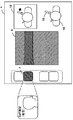
- the display processing unit 12 displays the probe image on the monitor 4, the reference probe image 19 read from the storage unit 13 (probe icon displayed at an angle according to past angle information.
- Reference probe icon 19 Is displayed in a mode (color, shape, etc.) different from the probe icon 15 (current probe icon 15).
- FIG. 7 is a diagram illustrating an example of the reference probe icon 19. In the example of FIG. 7, the reference probe icon 19 is displayed in a different color from the current probe icon.
- the display processing unit 12 causes the monitor 4 to display the reference probe icon 19 at a recommended angle set in advance according to the diagnosis mode. May be.
- the display processing unit 12 when displaying the past diagnostic image 6 (cine image) stored in the storage unit 13 on the monitor 4, the display processing unit 12 is stored in association with the past diagnostic image 6 (cine image). A function of displaying past angle information with the probe icon 15 is also provided.
- the display processing unit 12 may have a function of causing the monitor 4 to display an animation image 20 that guides the diagnosis procedure of the subject in the diagnosis mode. Operation buttons 21 such as “play / pause”, “fast forward”, and “rewind” of the animation image 20 may be displayed below the animation image 20 (see FIG. 8). When the diagnosis procedure guided by the animation image 20 is completed, the animation image 20 for guiding the next diagnosis procedure is displayed.
- the animation image 20 not only continuous images but also a plurality of still images may be displayed in order.
- the ultrasonic diagnostic apparatus 1 of the first embodiment by using the acceleration sensor 5 provided in the ultrasonic probe 3, there is no need to install a large-scale apparatus as in the prior art.
- the angle of the ultrasonic probe 3 when diagnosing the subject can be obtained and displayed.
- the acceleration information output from the acceleration sensor 5 provided in the ultrasonic probe 3 is converted into angle information, whereby a conventional large-scale device (for example, a probe can be provided).
- the angle of the ultrasonic probe 3 at the time of diagnosing the subject can be obtained and displayed on the monitor 4 without requiring a magnetic field generator that cannot be installed only on the bed.
- the acceleration sensor 5 is suitable for being provided in the ultrasonic probe 3 because it can be easily downsized.
- the monitor 4 on which the diagnostic image 6 is displayed includes a subject image (body mark 16) corresponding to the diagnostic mode selected by the user (doctor, technician, etc.). Since the probe image (probe icon 15) arranged at an angle corresponding to the angle information with respect to the subject image is displayed, the user can make a diagnosis from these images (image displayed on the monitor 4). Necessary information can be obtained sufficiently.
- the button image (workflow button 17) displayed on the monitor 4 is changed in order according to the diagnosis procedure of the subject.
- the diagnostic procedure can be easily and appropriately advanced using one button (workflow button 17).
- the button (workflow button 17) is changed to indicate the next diagnosis procedure, Displayed blinking. This can prompt the user to proceed to the next diagnostic procedure.
- the workflow button 17 indicates the next diagnostic procedure, “blinking is displayed” is used.
- the present invention is not limited to this, and alerts the user by changing the color or brightness, generating sound, and cooperating with the above. Any method can be used.
- the image data of the diagnostic image 6 obtained in the diagnostic mode (diagnostic mode before transition) and the angle information are associated with each other. Saved. Therefore, for example, when the diagnostic image 6 is obtained when the past diagnostic image 6 (diagnostic image 6 obtained in the diagnostic mode) is to be referred to, for example, when the diagnostic site is followed up. Information can be obtained together and contrasted using images obtained under the same conditions (same diagnostic mode and same angle).
- the current probe image (probe icon 15) when the current probe image (probe icon 15) is displayed, if the diagnosis has been performed in the same diagnosis mode in the past, the past A reference probe image (reference probe icon 19) when the diagnostic image 6 is obtained by diagnosis is displayed together.
- the reference probe image (reference probe icon 19) and the current probe image (probe icon 15) are displayed so that they can be distinguished from each other in different modes (different colors, shapes, etc.). Both can be easily distinguished.
- the user matches the reference probe image (reference probe icon 19) with the current probe image (probe icon 15), so that the same conditions as in the past diagnosis (in the same diagnosis mode and the same) Diagnosis).
- a recommended angle preset according to the diagnosis mode (according to the diagnosis mode) A reference probe image (reference probe icon 19) is displayed at an appropriate angle. Therefore, the user makes a diagnosis under appropriate conditions according to the diagnosis mode by matching the reference probe image (reference probe icon 19) with the current probe image (probe icon 15). be able to.
- the monitor 4 displays a guide image 18 indicating the direction in which the ultrasonic probe 3 should be tilted in the diagnostic mode.
- the guide image 18 is appropriately generated based on the past angle information and the current angle information. Therefore, the user can easily make a diagnosis according to the guide image 18 under the same conditions as the past diagnosis (in the same diagnosis mode and at the same angle).
- the guide image 18 has a recommended angle (appropriate angle according to the diagnosis mode) set in advance according to the diagnosis mode and a current value. Appropriately generated based on the angle information. Therefore, the user can easily make a diagnosis according to the guide image 18 under appropriate conditions according to the diagnosis mode.
- an animation image 20 that guides the diagnostic procedure of the subject is displayed on the monitor 4.
- the animation image 20 for guiding the next diagnosis procedure is displayed. The user can easily and appropriately proceed with the diagnosis procedure according to the animation image 20.
- the past diagnostic image 6 (cine image)
- the past angle information stored in association with the past diagnostic image 6 is displayed. Therefore, the user can see the angle information at the time of past diagnosis together with the diagnosis image 6 at the time of past diagnosis.
- the diagnostic image 6 is automatically analyzed to determine the diagnostic mode when the diagnostic image 6 is obtained, and the monitor 4 has an appropriate mode according to the diagnostic mode.
- a probe image (probe icon 15) is displayed. For example, as shown in FIG. 3, if the diagnostic mode 6 is determined to be “plaque search” as a result of image analysis of the diagnostic image 6, a probe image (probe icon 15) when performing “plaque search” Is displayed. As shown in FIG. 2, when the diagnostic mode is determined to be “IMT measurement” as a result of image analysis of the diagnostic image 6, a probe image (probe icon) for performing “IMT measurement” is displayed.
- the diagnostic image 6 is automatically analyzed by image analysis of the diagnostic image 6, and the diagnosis is performed in an appropriate storage area according to the diagnostic mode.
- Image data of image 6 and angle information are sorted and stored. For example, if it is determined that the diagnostic mode is “plaque search” as a result of image analysis of the diagnostic image 6, the image data and angle information of the diagnostic image 6 are stored in the storage area for “plaque search”. . Further, for example, when the diagnostic image is determined to be “IMT measurement” as a result of image analysis of the diagnostic image 6, the image data and angle information of the diagnostic image 6 are stored in the storage area for “IMT measurement”. .
- the monitor 4 is configured with a touch panel, the operability when selecting the diagnostic mode is improved.
- FIG. 9 is a block diagram showing the configuration of the ultrasonic diagnostic system of the present embodiment.
- the ultrasonic diagnostic system 100 includes an ultrasonic diagnostic apparatus 1 and a server apparatus 30.
- the ultrasonic diagnostic apparatus 1 and the server apparatus 30 are connected via a network 31 so that they can communicate with each other.
- the ultrasonic diagnostic apparatus 1 does not include the large-capacity storage unit 13.
- the ultrasound diagnostic apparatus 1 includes a communication unit 32 that communicates with the server device 30.
- the server device 30 includes a communication unit 33 that communicates with the ultrasound diagnostic apparatus 1 and a large-capacity storage unit 34.
- the server device 30 associates the image data of the diagnostic image 6 obtained in the diagnostic mode before the transition with the angle information. And is stored in the storage unit 34 of the server device 30.
- the same effects as those of the first embodiment can be obtained. That is, even with this ultrasonic diagnostic system 100, as in the case of the ultrasonic diagnostic apparatus 1 of the first embodiment, a conventional large-scale apparatus (for example, a probe cannot be provided, but only on a bed.
- the angle of the ultrasonic probe 3 when diagnosing the subject can be obtained and displayed on the monitor 4 without requiring a magnetic field generator that cannot be installed, and the user can display the angle on the monitor 4. Information necessary for diagnosis can be sufficiently obtained from the image to be obtained.
- the image data of the diagnostic image 6 obtained in the diagnostic mode (diagnostic mode before transition) and the angle information are associated with each other. Then, it is transmitted from the ultrasonic device to the server device 30 and stored in the storage unit 34 of the server device 30. Therefore, for example, when the past diagnostic image 6 (diagnostic image 6 obtained in the diagnostic mode) is to be referred to, such as when the diagnostic site is being followed, the ultrasonic diagnostic apparatus 1 Angle information when the diagnostic image 6 is obtained from the storage unit 34 can be obtained together, and comparative observation is performed using images obtained under the same conditions (the same diagnostic mode and the same angle). Can do.
- FIG. 10 is a perspective view showing a usage state (bending state) of the folding pillow 35
- FIG. 11 is a perspective view showing a storage state (extended state) of the folding pillow 35.
- the folding pillow 35 is composed of four plate-like portions 36 connected to each other, and the adjacent plate-like portions 36 are connected to each other by end portions 37 (connecting portions).
- the folding pillow 35 is made of a material such as low-foam urethane.
- the folding pillow 35 When the folding pillow 35 is put into use, as shown in FIG. 10, the folding pillow 35 is folded to form a triangular pillar-shaped three-dimensional pillow portion 38 using three plate-like portions 36. The subject places his head on the remaining plate-like portion 36 and tilts the head to bring the side of the head into contact with the three-dimensional pillow portion 38. As a result, as shown in FIG. 12, the state in which the head is inclined at a certain angle can be easily maintained, and the operability and reproducibility of diagnosis can be improved. After use, the folding pillow 35 is extended as shown in FIG. Thereby, it can be stored in a small storage space.
- the ultrasonic diagnostic apparatus does not require the installation of a large-scale apparatus as in the prior art, and obtains and displays the angle of the ultrasonic probe when diagnosing a subject. It can be applied mainly in the medical field and is useful.
Abstract
Description
本発明の第1の実施の形態の超音波診断装置の構成を、図面を参照して説明する。図1は、本実施の形態の超音波診断装置の構成を示すブロック図である。図1に示すように、超音波診断装置1は、操作入力部2と超音波プローブ3とモニタ4(表示部)を備えている。操作入力部2は、例えば、キーボードやマウス、操作ボタン、トラックボールなどを備えた操作卓である。この操作入力部2は、各種の情報入力やコマンド入力、パラメータ情報の設定変更などを行うために用いられる。超音波プローブ3は、超音波振動子(図示せず)から被検体へ超音波パルスを照射し、体内の各組織からの反射超音波を受信して電気信号に変換する超音波探触子である。この超音波プローブ3には、被検体を診断しているときの超音波プローブ3の加速度情報(重力加速度の情報)を出力する加速度センサ5が設けられている。モニタ4には、超音波プローブ3によって得られた被検体の診断画像6が表示される(図2など参照)。また、このモニタ4は、タッチパネルで構成されており、超音波プローブ3で被検体を診断するときの診断モードをタッチ操作で選択する機能を備えている。
次に、本発明の第2の実施の形態の超音波診断システムについて説明する。ここでは、第2の実施の形態の超音波診断システムが、第1の実施の形態と相違する点を中心に説明する。ここで特に言及しない限り、本実施の形態の構成および動作は、第1の実施の形態と同様である。
2 操作入力部
3 超音波プローブ
4 モニタ
5 加速度センサ
6 診断画像
7 診断モードボタン
8 送信部
9 受信部
10 信号処理部
11 角度変換部
12 表示処理部
13 記憶部
14 制御部
15 プローブアイコン
16 ボディーマーク
17 ワークフローボタン
18 ガイド画像
19 参照用プローブアイコン
20 アニメーション画像
21 操作ボタン
30 サーバ装置
31 ネットワーク
32 通信部
33 通信部
34 記憶部
35 折り曲げ枕
36 板状部
37 端部
38 立体枕部
39 表示領域
100 超音波診断システム
Claims (20)
- 超音波プローブと、
前記超音波プローブに設けられ、被検体を診断しているときの前記超音波プローブの重力方向に対する相対的な角度を求めるためのセンサ情報を出力するセンサと、
前記センサ情報を、前記超音波プローブの角度情報に変換する角度変換部と、
前記角度情報を前記表示部に表示させる表示処理部と、
を備えたことを特徴とする超音波診断装置。 - 前記表示処理部は、前記角度情報を前記被検体に対する前記超音波プローブの相対的な角度として、前記表示部に表示させることを特徴とする請求項1に記載の超音波診断装置。
- 前記超音波プローブを模式的な図形として表したプローブ画像と、前記被検体を模式的な図形として表した被検体画像とを生成するが画像生成部を備え、
前記表示処理部は、前記被検体画像と前記プローブ画像とを表示部に表示させ、前記プローブ画像を前記被検体画像に対して所定の位置関係を有する領域内に前記角度情報に応じた角度で配置することを特徴とする請求項2に記載の超音波診断装置。 - 前記表示処理部は、前記プローブ画像を前記プローブ画像の方向によって、前記角度情報に応じた角度を表示させることを特徴とする請求項3に記載の超音波診断装置。
- 前記表示処理部は、前記領域を前記被検体画像上に設定し、前記プローブ画像を前記被検体画像に接触しているように前記表示部に表示させることを特徴とする請求項3または請求項4に記載の超音波診断装置。
- 前記センサは、加速度センサであり、前記超音波プローブの角度を求めるための情報として、前記超音波プローブの加速度情報を出力し、
前記角度変換部は、前記加速度情報を、前記超音波プローブの角度情報に変換することを特徴とする請求項1ないし請求項5のいずれかに記載の超音波診断装置。 - 前記表示処理部は、前記表示部に、前記被検体の診断手順に応じて順番にボタン名が変更されるボタン画像を表示させることを特徴とする請求項1ないし請求項6のいずれかに記載の超音波診断装置。
- 前記表示処理部は、前記ボタン名によって示された診断手順が完了した場合に、前記表示部に、次の診断手順を示すボタン画像を点滅状態で表示させることを特徴とする請求項7に記載の超音波診断装置。
- 前記超音波プローブで前記被検体を診断するときの診断モードを選択する診断モード選択部を備えたことを特徴とする請求項1ないし請求項8のいずれかに記載の超音波診断装置。
- 前記被検体の診断画像の画像データが記憶される記憶部と、
前記被検体の診断モードが次の診断モードへ移行したときに、移行前の診断モードで得られた前記診断画像の画像データと前記角度情報とを関連づけて、前記記憶部に記憶させる記憶処理部と、
を備えたことを特徴とする請求項9に記載の超音波診断装置。 - 前記表示処理部は、前記表示部に、前記プローブ画像を表示するときに、前記記憶部から読み出した過去の前記角度情報に応じた角度で表示する参照用プローブ画像を、前記プローブ画像と区別して表示させることを特徴とする請求項10に記載の超音波診断装置。
- 前記表示処理部は、前記記憶部に過去の角度情報が記憶されていない場合に、前記表示部に、前記診断モードに応じて予め設定された推奨角度で前記参照用プローブ画像を表示させることを特徴とする請求項11に記載の超音波診断装置。
- 前記表示処理部は、前記表示部に、前記診断モードにおいて前記超音波プローブを傾けるべき方向を示したガイド画像を表示させ、
前記ガイド画像は、
前記記憶部に過去の角度情報が記憶されている場合には、前記記憶部から読み出した過去の角度情報と前記センサ情報から変換した現在の角度情報とに基づいて生成され、
前記記憶部に過去の角度情報が記憶されていない場合には、前記診断モードに応じて予め設定された推奨角度と前記センサ情報から変換した現在の角度情報とに基づいて生成されることを特徴とする請求項10ないし請求項12のいずれかに記載の超音波診断装置。 - 前記表示処理部は、前記表示部に、前記診断モードにおける前記被検体の診断手順をガイドするアニメーション画像を表示させるものであり、前記アニメーション画像によってガイドされた前記診断手順が完了した場合に、次の診断手順をガイドするアニメーション画像を表示させることを特徴とする請求項1ないし請求項13のいずれかに記載の超音波診断装置。
- 前記表示処理部は、前記表示部に、前記記憶部に記憶された過去の診断画像を表示させるときに、前記過去の診断画像に関連付けて記憶された過去の角度情報を表示させることを特徴とする請求項10ないし請求項14のいずれかに記載の超音波診断装置。
- 前記診断画像を画像解析することにより、前記診断画像が得られたときの診断モードを判定する診断モード判定部を備え、
前記表示処理部は、前記表示部に、前記診断モード判定部で判定された診断モードに応じたプローブ画像を表示させることを特徴とする請求項1ないし請求項15のいずれかに記載の超音波診断装置。 - 前記診断画像を画像解析することにより、前記診断画像が得られたときの診断モードを判定する診断モード判定部を備え、
前記記憶部は、前記被検体の診断モード別に、前記診断画像の画像データと前記角度情報が記憶される記憶領域を備え、
前記記憶処理部は、前記診断モード判定部で判定された診断モードに応じた記憶領域に、前記診断画像の画像データと前記角度情報を振り分けて記憶させることを特徴とする請求項10ないし請求項16のいずれかに記載の超音波診断装置。 - 前記表示部は、タッチパネルであり、前記診断モードの選択は、前記タッチパネルのタッチ操作により行われることを特徴とする請求項1ないし請求項17のいずれかに記載の超音波診断装置。
- 超音波プローブと、
前記超音波プローブに設けられ、被検体を診断しているときの前記超音波プローブの角度を求めるためのセンサ情報を出力するセンサと、
前記センサ情報を、前記超音波プローブの角度情報に変換する角度変換部と、
前記超音波プローブを模式的な図形として表したプローブ画像と、前記被検体を模式的な図形として表した被検体画像とを生成する画像生成部と、
前記被検体画像と前記プローブ画像とを表示部に表示させ、前記角度情報を前記被検体に対する前記超音波プローブの角度として、前記プローブ画像を前記被検体画像に対して所定の位置関係を有する領域内に前記角度情報に応じた角度で配置する表示処理部と、
を備えたことを特徴とする超音波診断システム。 - 前記超音波診断システムは、超音波診断装置と、前記超音波診断装置と通信可能に接続されるサーバ装置とで構成され、
前記サーバ装置は、
前記被検体の診断画像の画像データが記憶される記憶部を備え、
前記超音波診断装置は、
前記被検体の診断モードが次の診断モードへ移行したときに、移行前の診断モードで得られた前記診断画像の画像データと前記角度情報とを関連づけて、前記サーバ装置へ送信して、前記サーバ装置の記憶部に記憶させる記憶処理部を備えたことを特徴とする請求項19に記載の超音波診断システム。
Priority Applications (4)
| Application Number | Priority Date | Filing Date | Title |
|---|---|---|---|
| US13/636,835 US9498185B2 (en) | 2010-11-12 | 2011-10-27 | Ultrasound diagnostic apparatus and ultrasound diagnostic system |
| EP11839185.3A EP2638859A4 (en) | 2010-11-12 | 2011-10-27 | ULTRASONIC DIAGNOSTIC APPARATUS AND ULTRASONIC DIAGNOSTIC SYSTEM |
| JP2012506240A JP5842810B2 (ja) | 2010-11-12 | 2011-10-27 | 超音波診断装置および超音波診断システム |
| CN201180018233.9A CN102843973B (zh) | 2010-11-12 | 2011-10-27 | 超声波诊断装置和超声波诊断系统 |
Applications Claiming Priority (2)
| Application Number | Priority Date | Filing Date | Title |
|---|---|---|---|
| JP2010-253738 | 2010-11-12 | ||
| JP2010253738 | 2010-11-12 |
Publications (1)
| Publication Number | Publication Date |
|---|---|
| WO2012063420A1 true WO2012063420A1 (ja) | 2012-05-18 |
Family
ID=46050591
Family Applications (1)
| Application Number | Title | Priority Date | Filing Date |
|---|---|---|---|
| PCT/JP2011/006009 WO2012063420A1 (ja) | 2010-11-12 | 2011-10-27 | 超音波診断装置および超音波診断システム |
Country Status (5)
| Country | Link |
|---|---|
| US (1) | US9498185B2 (ja) |
| EP (1) | EP2638859A4 (ja) |
| JP (1) | JP5842810B2 (ja) |
| CN (1) | CN102843973B (ja) |
| WO (1) | WO2012063420A1 (ja) |
Cited By (4)
| Publication number | Priority date | Publication date | Assignee | Title |
|---|---|---|---|---|
| JP2013255545A (ja) * | 2012-06-11 | 2013-12-26 | Panasonic Corp | 超音波診断装置および超音波診断装置の制御方法 |
| WO2014027679A1 (ja) * | 2012-08-17 | 2014-02-20 | 株式会社 東芝 | 超音波診断装置 |
| CN105025799A (zh) * | 2012-12-18 | 2015-11-04 | 米轨公司 | 用于诊断超声机器的三维映射显示系统 |
| EP4252668A1 (en) | 2022-03-30 | 2023-10-04 | FUJIFILM Corporation | Ultrasound diagnostic apparatus and operation method thereof |
Families Citing this family (15)
| Publication number | Priority date | Publication date | Assignee | Title |
|---|---|---|---|---|
| KR101925058B1 (ko) | 2012-04-26 | 2018-12-04 | 삼성전자주식회사 | 초음파 장치의 버튼의 기능을 버튼에 디스플레이하는 방법 및 장치 |
| JP6342164B2 (ja) * | 2013-01-23 | 2018-06-13 | キヤノンメディカルシステムズ株式会社 | 超音波診断装置 |
| US20140249405A1 (en) * | 2013-03-01 | 2014-09-04 | Igis Inc. | Image system for percutaneous instrument guidence |
| KR20150003560A (ko) * | 2013-07-01 | 2015-01-09 | 삼성전자주식회사 | 사용자의 모션 정보에 기초하여 사용자 인터페이스(ui)를 변경시키는 방법 및 장치 |
| CN104013423B (zh) * | 2014-05-09 | 2016-07-13 | 杨松 | B超扫描探头、b超扫描系统和b超扫描方法 |
| US10292122B2 (en) * | 2014-10-11 | 2019-05-14 | Telefonaktiebolaget Lm Ericsson (Publ) | Method and access point for maintaining synchronization among access points in radio access network |
| WO2016198413A1 (en) * | 2015-06-10 | 2016-12-15 | Koninklijke Philips N.V. | Ultrasound imaging apparatus |
| WO2017013511A1 (en) | 2015-07-21 | 2017-01-26 | Koninklijke Philips N.V. | Ultrasound system with processor dongle |
| CN105943161A (zh) * | 2016-06-04 | 2016-09-21 | 深圳市前海康启源科技有限公司 | 基于医疗机器人的手术导航系统及方法 |
| FR3059224A1 (fr) * | 2016-11-28 | 2018-06-01 | Quantel Medical | Procede d'echographie ophtalmique |
| JP6718520B2 (ja) * | 2016-12-06 | 2020-07-08 | 富士フイルム株式会社 | 超音波診断装置及び超音波診断装置の制御方法 |
| KR20180066781A (ko) | 2016-12-09 | 2018-06-19 | 삼성전자주식회사 | 의료 영상을 표시하는 방법 및 장치 |
| CN108095758A (zh) * | 2017-12-22 | 2018-06-01 | 飞依诺科技(苏州)有限公司 | 一种超声扫查探头方位实时更新方法及系统 |
| US11771399B2 (en) | 2018-02-07 | 2023-10-03 | Atherosys, Inc. | Apparatus and method to guide ultrasound acquisition of the peripheral arteries in the transverse plane |
| CN109602451B (zh) * | 2019-02-16 | 2021-08-10 | 河南科技大学第一附属医院(河南省显微外科研究所) | 一种医学超声辅助自动诊断系统 |
Citations (9)
| Publication number | Priority date | Publication date | Assignee | Title |
|---|---|---|---|---|
| JP2004057379A (ja) * | 2002-07-26 | 2004-02-26 | Aloka Co Ltd | 超音波診断装置 |
| JP2005124712A (ja) * | 2003-10-22 | 2005-05-19 | Aloka Co Ltd | 超音波診断装置 |
| JP2008068133A (ja) * | 2007-12-03 | 2008-03-27 | Toshiba Corp | 超音波診断装置 |
| JP2008279272A (ja) * | 2003-05-08 | 2008-11-20 | Hitachi Medical Corp | 超音波診断装置 |
| JP2009077960A (ja) * | 2007-09-26 | 2009-04-16 | Toshiba Corp | 超音波画像診断装置 |
| JP2009089736A (ja) * | 2007-10-03 | 2009-04-30 | Toshiba Corp | 超音波診断装置 |
| JP2009268735A (ja) * | 2008-05-08 | 2009-11-19 | Toshiba Corp | 医用画像処理装置 |
| JP2010172701A (ja) * | 2009-01-28 | 2010-08-12 | Medison Co Ltd | 映像指示子を提供する超音波システムおよび方法 |
| JP2010221011A (ja) * | 2009-02-27 | 2010-10-07 | Toshiba Corp | 超音波撮影装置、画像処理装置、画像処理方法及びコンピュータプログラムプロダクト |
Family Cites Families (9)
| Publication number | Priority date | Publication date | Assignee | Title |
|---|---|---|---|---|
| US5881723A (en) * | 1997-03-14 | 1999-03-16 | Nellcor Puritan Bennett Incorporated | Ventilator breath display and graphic user interface |
| JP4088104B2 (ja) | 2002-06-12 | 2008-05-21 | 株式会社東芝 | 超音波診断装置 |
| JP2005270317A (ja) | 2004-03-24 | 2005-10-06 | Toshiba Corp | 超音波画像診断装置 |
| JP4490715B2 (ja) | 2004-03-25 | 2010-06-30 | 株式会社東芝 | 超音波診断装置 |
| JP2006192030A (ja) | 2005-01-12 | 2006-07-27 | Toshiba Corp | 超音波画像診断装置 |
| KR100752333B1 (ko) * | 2005-01-24 | 2007-08-28 | 주식회사 메디슨 | 3차원 초음파 도플러 이미지의 화질 개선 방법 |
| JP4079379B2 (ja) * | 2005-12-26 | 2008-04-23 | エッチ・アール・エス コンサルタントサービス有限会社 | 心エコー診断教育装置 |
| JP4894498B2 (ja) | 2006-12-20 | 2012-03-14 | パナソニック株式会社 | 超音波診断装置 |
| JP5322600B2 (ja) | 2008-11-19 | 2013-10-23 | 株式会社東芝 | 超音波診断装置 |
-
2011
- 2011-10-27 EP EP11839185.3A patent/EP2638859A4/en not_active Withdrawn
- 2011-10-27 CN CN201180018233.9A patent/CN102843973B/zh not_active Expired - Fee Related
- 2011-10-27 US US13/636,835 patent/US9498185B2/en active Active
- 2011-10-27 WO PCT/JP2011/006009 patent/WO2012063420A1/ja active Application Filing
- 2011-10-27 JP JP2012506240A patent/JP5842810B2/ja active Active
Patent Citations (10)
| Publication number | Priority date | Publication date | Assignee | Title |
|---|---|---|---|---|
| JP2004057379A (ja) * | 2002-07-26 | 2004-02-26 | Aloka Co Ltd | 超音波診断装置 |
| JP2008279272A (ja) * | 2003-05-08 | 2008-11-20 | Hitachi Medical Corp | 超音波診断装置 |
| JP2005124712A (ja) * | 2003-10-22 | 2005-05-19 | Aloka Co Ltd | 超音波診断装置 |
| JP4263579B2 (ja) | 2003-10-22 | 2009-05-13 | アロカ株式会社 | 超音波診断装置 |
| JP2009077960A (ja) * | 2007-09-26 | 2009-04-16 | Toshiba Corp | 超音波画像診断装置 |
| JP2009089736A (ja) * | 2007-10-03 | 2009-04-30 | Toshiba Corp | 超音波診断装置 |
| JP2008068133A (ja) * | 2007-12-03 | 2008-03-27 | Toshiba Corp | 超音波診断装置 |
| JP2009268735A (ja) * | 2008-05-08 | 2009-11-19 | Toshiba Corp | 医用画像処理装置 |
| JP2010172701A (ja) * | 2009-01-28 | 2010-08-12 | Medison Co Ltd | 映像指示子を提供する超音波システムおよび方法 |
| JP2010221011A (ja) * | 2009-02-27 | 2010-10-07 | Toshiba Corp | 超音波撮影装置、画像処理装置、画像処理方法及びコンピュータプログラムプロダクト |
Non-Patent Citations (1)
| Title |
|---|
| See also references of EP2638859A4 * |
Cited By (7)
| Publication number | Priority date | Publication date | Assignee | Title |
|---|---|---|---|---|
| JP2013255545A (ja) * | 2012-06-11 | 2013-12-26 | Panasonic Corp | 超音波診断装置および超音波診断装置の制御方法 |
| WO2014027679A1 (ja) * | 2012-08-17 | 2014-02-20 | 株式会社 東芝 | 超音波診断装置 |
| JP2014036754A (ja) * | 2012-08-17 | 2014-02-27 | Toshiba Corp | 超音波診断装置 |
| CN103930039A (zh) * | 2012-08-17 | 2014-07-16 | 株式会社东芝 | 超声波诊断装置 |
| CN103930039B (zh) * | 2012-08-17 | 2016-12-14 | 东芝医疗系统株式会社 | 超声波诊断装置 |
| CN105025799A (zh) * | 2012-12-18 | 2015-11-04 | 米轨公司 | 用于诊断超声机器的三维映射显示系统 |
| EP4252668A1 (en) | 2022-03-30 | 2023-10-04 | FUJIFILM Corporation | Ultrasound diagnostic apparatus and operation method thereof |
Also Published As
| Publication number | Publication date |
|---|---|
| JPWO2012063420A1 (ja) | 2014-05-12 |
| EP2638859A4 (en) | 2015-08-26 |
| US20130018263A1 (en) | 2013-01-17 |
| CN102843973A (zh) | 2012-12-26 |
| CN102843973B (zh) | 2017-02-08 |
| US9498185B2 (en) | 2016-11-22 |
| JP5842810B2 (ja) | 2016-01-13 |
| EP2638859A1 (en) | 2013-09-18 |
Similar Documents
| Publication | Publication Date | Title |
|---|---|---|
| JP5842810B2 (ja) | 超音波診断装置および超音波診断システム | |
| KR101705120B1 (ko) | 자가 진단 및 원격 진단을 위한 초음파 진단 장치 및 초음파 진단 장치의 동작 방법 | |
| JP4467927B2 (ja) | 超音波診断装置 | |
| EP3192053B1 (en) | Quality metric for multi-beat echocardiographic acquisitions for immediate user feedback | |
| US5967985A (en) | Ultrasonic diagnostic apparatus | |
| US9480457B2 (en) | Ultrasound diagnostic device and ultrasound image display method | |
| JP5322600B2 (ja) | 超音波診断装置 | |
| JP2009066074A (ja) | 超音波診断装置 | |
| WO2012017827A1 (ja) | 超音波画像装置と超音波画像を用いた三次元画像表示方法 | |
| JP5717543B2 (ja) | 超音波診断装置及びその制御プログラム | |
| WO2012164892A1 (ja) | 超音波診断装置および超音波を用いた画像取得方法 | |
| US20140171800A1 (en) | Ultrasound diagnostic device and ultrasound image display method | |
| JP7145107B2 (ja) | 超音波診断装置及び表示方法 | |
| JP6026455B2 (ja) | 医用画像表示装置およびその作動方法並びにプログラム | |
| JP2008245788A (ja) | 超音波観測装置及びこの超音波観測装置を用いた超音波診断装置 | |
| JP4879623B2 (ja) | 超音波診断装置 | |
| WO2021029153A1 (ja) | 超音波診断装置、及び超音波診断装置の制御方法 | |
| JP2006333896A (ja) | 超音波診断装置、超音波診断方法及び超音波診断プログラム | |
| JP2014161598A (ja) | 超音波診断装置及びその制御プログラム | |
| KR20190085342A (ko) | 초음파 진단 장치의 제어 방법 및 초음파 진단 장치 | |
| US6743176B2 (en) | Ultrasonic image display apparatus and ultrasonic image display method | |
| JP2009101073A (ja) | 超音波撮像装置 | |
| KR20130124750A (ko) | 초음파 진단 장치 및 그 제어방법 | |
| US20210290203A1 (en) | Ultrasound system and method for guided shear wave elastography of anisotropic tissue | |
| JP2009061076A (ja) | 超音波診断装置 |
Legal Events
| Date | Code | Title | Description |
|---|---|---|---|
| WWE | Wipo information: entry into national phase |
Ref document number: 201180018233.9 Country of ref document: CN |
|
| WWE | Wipo information: entry into national phase |
Ref document number: 2012506240 Country of ref document: JP |
|
| 121 | Ep: the epo has been informed by wipo that ep was designated in this application |
Ref document number: 11839185 Country of ref document: EP Kind code of ref document: A1 |
|
| WWE | Wipo information: entry into national phase |
Ref document number: 13636835 Country of ref document: US |
|
| WWE | Wipo information: entry into national phase |
Ref document number: 2751/MUMNP/2012 Country of ref document: IN |
|
| WWE | Wipo information: entry into national phase |
Ref document number: 2011839185 Country of ref document: EP |
|
| NENP | Non-entry into the national phase |
Ref country code: DE |