WO2012056894A1 - 船舶推進装置 - Google Patents
船舶推進装置 Download PDFInfo
- Publication number
- WO2012056894A1 WO2012056894A1 PCT/JP2011/073537 JP2011073537W WO2012056894A1 WO 2012056894 A1 WO2012056894 A1 WO 2012056894A1 JP 2011073537 W JP2011073537 W JP 2011073537W WO 2012056894 A1 WO2012056894 A1 WO 2012056894A1
- Authority
- WO
- WIPO (PCT)
- Prior art keywords
- clutch
- engine
- state
- speed
- propeller
- Prior art date
- Legal status (The legal status is an assumption and is not a legal conclusion. Google has not performed a legal analysis and makes no representation as to the accuracy of the status listed.)
- Ceased
Links
Images




Classifications
-
- B—PERFORMING OPERATIONS; TRANSPORTING
- B63—SHIPS OR OTHER WATERBORNE VESSELS; RELATED EQUIPMENT
- B63H—MARINE PROPULSION OR STEERING
- B63H23/00—Transmitting power from propulsion power plant to propulsive elements
- B63H23/30—Transmitting power from propulsion power plant to propulsive elements characterised by use of clutches
-
- B—PERFORMING OPERATIONS; TRANSPORTING
- B63—SHIPS OR OTHER WATERBORNE VESSELS; RELATED EQUIPMENT
- B63H—MARINE PROPULSION OR STEERING
- B63H21/00—Use of propulsion power plant or units on vessels
- B63H21/21—Control means for engine or transmission, specially adapted for use on marine vessels
-
- F—MECHANICAL ENGINEERING; LIGHTING; HEATING; WEAPONS; BLASTING
- F02—COMBUSTION ENGINES; HOT-GAS OR COMBUSTION-PRODUCT ENGINE PLANTS
- F02D—CONTROLLING COMBUSTION ENGINES
- F02D29/00—Controlling engines, such controlling being peculiar to the devices driven thereby, the devices being other than parts or accessories essential to engine operation, e.g. controlling of engines by signals external thereto
- F02D29/02—Controlling engines, such controlling being peculiar to the devices driven thereby, the devices being other than parts or accessories essential to engine operation, e.g. controlling of engines by signals external thereto peculiar to engines driving vehicles; peculiar to engines driving variable pitch propellers
-
- F—MECHANICAL ENGINEERING; LIGHTING; HEATING; WEAPONS; BLASTING
- F16—ENGINEERING ELEMENTS AND UNITS; GENERAL MEASURES FOR PRODUCING AND MAINTAINING EFFECTIVE FUNCTIONING OF MACHINES OR INSTALLATIONS; THERMAL INSULATION IN GENERAL
- F16D—COUPLINGS FOR TRANSMITTING ROTATION; CLUTCHES; BRAKES
- F16D25/00—Fluid-actuated clutches
- F16D25/06—Fluid-actuated clutches in which the fluid actuates a piston incorporated in, i.e. rotating with the clutch
- F16D25/062—Fluid-actuated clutches in which the fluid actuates a piston incorporated in, i.e. rotating with the clutch the clutch having friction surfaces
- F16D25/063—Fluid-actuated clutches in which the fluid actuates a piston incorporated in, i.e. rotating with the clutch the clutch having friction surfaces with clutch members exclusively moving axially
- F16D25/0635—Fluid-actuated clutches in which the fluid actuates a piston incorporated in, i.e. rotating with the clutch the clutch having friction surfaces with clutch members exclusively moving axially with flat friction surfaces, e.g. discs
- F16D25/0638—Fluid-actuated clutches in which the fluid actuates a piston incorporated in, i.e. rotating with the clutch the clutch having friction surfaces with clutch members exclusively moving axially with flat friction surfaces, e.g. discs with more than two discs, e.g. multiple lamellae
-
- F—MECHANICAL ENGINEERING; LIGHTING; HEATING; WEAPONS; BLASTING
- F16—ENGINEERING ELEMENTS AND UNITS; GENERAL MEASURES FOR PRODUCING AND MAINTAINING EFFECTIVE FUNCTIONING OF MACHINES OR INSTALLATIONS; THERMAL INSULATION IN GENERAL
- F16D—COUPLINGS FOR TRANSMITTING ROTATION; CLUTCHES; BRAKES
- F16D25/00—Fluid-actuated clutches
- F16D25/12—Details not specific to one of the before-mentioned types
- F16D25/123—Details not specific to one of the before-mentioned types in view of cooling and lubrication
-
- F—MECHANICAL ENGINEERING; LIGHTING; HEATING; WEAPONS; BLASTING
- F16—ENGINEERING ELEMENTS AND UNITS; GENERAL MEASURES FOR PRODUCING AND MAINTAINING EFFECTIVE FUNCTIONING OF MACHINES OR INSTALLATIONS; THERMAL INSULATION IN GENERAL
- F16D—COUPLINGS FOR TRANSMITTING ROTATION; CLUTCHES; BRAKES
- F16D48/00—External control of clutches
- F16D48/06—Control by electric or electronic means, e.g. of fluid pressure
- F16D48/08—Regulating clutch take-up on starting
-
- B—PERFORMING OPERATIONS; TRANSPORTING
- B63—SHIPS OR OTHER WATERBORNE VESSELS; RELATED EQUIPMENT
- B63H—MARINE PROPULSION OR STEERING
- B63H21/00—Use of propulsion power plant or units on vessels
- B63H21/21—Control means for engine or transmission, specially adapted for use on marine vessels
- B63H2021/216—Control means for engine or transmission, specially adapted for use on marine vessels using electric control means
-
- F—MECHANICAL ENGINEERING; LIGHTING; HEATING; WEAPONS; BLASTING
- F16—ENGINEERING ELEMENTS AND UNITS; GENERAL MEASURES FOR PRODUCING AND MAINTAINING EFFECTIVE FUNCTIONING OF MACHINES OR INSTALLATIONS; THERMAL INSULATION IN GENERAL
- F16D—COUPLINGS FOR TRANSMITTING ROTATION; CLUTCHES; BRAKES
- F16D2500/00—External control of clutches by electric or electronic means
- F16D2500/30—Signal inputs
- F16D2500/306—Signal inputs from the engine
- F16D2500/3067—Speed of the engine
-
- F—MECHANICAL ENGINEERING; LIGHTING; HEATING; WEAPONS; BLASTING
- F16—ENGINEERING ELEMENTS AND UNITS; GENERAL MEASURES FOR PRODUCING AND MAINTAINING EFFECTIVE FUNCTIONING OF MACHINES OR INSTALLATIONS; THERMAL INSULATION IN GENERAL
- F16D—COUPLINGS FOR TRANSMITTING ROTATION; CLUTCHES; BRAKES
- F16D2500/00—External control of clutches by electric or electronic means
- F16D2500/70—Details about the implementation of the control system
- F16D2500/704—Output parameters from the control unit; Target parameters to be controlled
- F16D2500/70422—Clutch parameters
- F16D2500/70426—Clutch slip
Definitions
- the present invention relates to a ship propulsion device for propelling a ship.
- FIG. 10 is a schematic configuration diagram of a conventional marine vessel propulsion apparatus.
- the marine vessel propulsion apparatus 100 includes a propeller 101 for propelling the marine vessel, an engine 102 for rotating the propeller 101, and a speed reduction reverser 103 that can transmit the rotation of the engine 102 to the propeller 101.
- the reduction reverse rotation machine 103 includes a clutch (not shown) inside.
- the marine vessel propulsion apparatus 100 includes an input device 104 that can input the state of the clutch in the speed reduction reverser 103, and a control device 105 that controls the state of the clutch and the operation of the engine 102.
- the control apparatus 105 When the ship is propelled by the ship propulsion apparatus 100 having such a configuration, first, the control apparatus 105 is turned on by turning on a switch (not shown) in a state where the clutch in the speed reduction reverser 103 is disengaged. 102 is activated. Next, when the engine 102 is in operation, the control device 105 places the clutch in the half-clutch state by inputting with the input device 104 so that the clutch of the speed reduction reverser 103 is in the half-clutch state. As a result, the rotation of the engine 102 is transmitted to the propeller 101 via the clutch of the speed reduction reverser 103, so that the propeller 101 starts to rotate.
- the control device 105 places the clutch in the connected state by inputting the input device 104 so that the clutch is in the connected state. Thereby, the clutch is completely connected, and all the rotations of the engine 102 are transmitted to the propeller 101 via the clutch. As a result, the propeller 101 rotates completely.
- the propeller 101 can be rotated by moving the clutch of the speed reduction reverser 103 from the disconnected state through the half-clutch state, thereby propelling the ship.
- the rotation speed of the propeller 101 may increase rapidly. This is because part of the rotation of the engine 102 is transmitted to the propeller 101 and not all of the rotation of the engine 102 is transmitted to the propeller 101 when the clutch of the speed reducer 103 is in the half-clutch state. Therefore, although the propeller 101 rotates at a lower speed than when the clutch is in the engaged state, a stable half-clutch state cannot be obtained near the boundary between the half-clutch state and the connected state. This is because the rotation of 101 may increase rapidly. As a result, it was difficult to smoothly control the rotation of the propeller 101, and it was difficult to smoothly change the ship speed. Therefore, there was room for improvement in this respect.
- the present invention has been made to solve the above-described problems, and an object of the present invention is to provide a ship propulsion device that can smoothly control the speed of a ship.
- the present invention is a marine vessel propulsion device for solving the above-described problem, and includes a propeller for propelling the marine vessel, an engine for rotating the propeller, and a clutch capable of transmitting the rotation of the engine to the propeller. And an input means capable of inputting the state of the clutch, a rotational speed detection means for detecting the rotational speed of the propeller, and a control means for controlling the operation of the engine and the state of the clutch.
- the clutch When the clutch is in the disengaged state, the engine is operated at the first engine speed, and the clutch is changed from the disengaged state to the half-clutch state based on the input from the input means, and the engine is The engine is operated at a second engine speed greater than the engine speed, and the engine is operated on the basis of detection by the rotation speed detecting means. Is operated at the engine speed low engine speed than the number, based on an input in said input means, said clutch is a boat propulsion unit to the connected state from the half-clutch state.
- the engine speed is set to the second engine speed higher than the first engine speed, so that the speed of the propeller in the half-clutch state is increased. be able to. Then, once the propeller speed is increased, the engine speed is made smaller than the second engine speed, and the clutch is changed from the half-clutch state to the connected state.
- the propeller rotation speed in the connected state can be made closer. In other words, if the clutch is brought into the engaged state without once increasing the engine speed, the propeller rotational speed rapidly increases when changing from the half-clutch state to the engaged state, resulting in a rapid change in the ship speed.
- the propeller rotational speeds in both states can be made closer to each other, so that the propeller rotational speed can be prevented from increasing suddenly.
- the propeller rotational speed increases smoothly, so that the speed of the ship can be controlled smoothly.
- Such a configuration is particularly effective because a half-clutch state is used when the ship is held at a fixed point offshore or stopped on the shore.
- Patent Document 1 there has been a configuration in which the number of revolutions of the propeller is controlled by controlling the hydraulic pressure of the clutch. Since it was not increased, there was a limit even when trying to increase the propeller rotation speed. Accordingly, the inventors of the present application have found that the number of revolutions of the propeller is increased by increasing the number of revolutions of the engine in the half-clutch state. Further, in contrast to the configuration in which the rotation speed of the propeller is controlled by controlling the hydraulic pressure of the clutch described in Patent Document 1, the knowledge that the rotation speed of the propeller is increased by increasing the rotation speed of the engine only in the half-clutch state Applying is not easy because the control target is different. The present invention is based on such knowledge.
- control means may return the engine speed from the second engine speed to the first engine speed based on the detection by the speed detection means. it can.
- the ship propulsion apparatus according to the present invention can start the ship smoothly.
- FIG. 1 is an overall view of a ship propulsion device according to an embodiment of the present invention. It is a schematic block diagram of a clutch, (a) is a figure which shows a disconnection state, (b) is a figure which shows a connection state. It is a schematic block diagram of an input device. It is a block diagram of a ship propulsion apparatus. It is a flowchart which shows the process in a ship propulsion apparatus. It is a flowchart which shows a part of process in a ship propulsion apparatus. It is a flowchart which shows the other part of the process in a ship propulsion apparatus. It is a graph which shows the process in a ship propulsion apparatus. It is a schematic block diagram of the input device which concerns on other embodiment, (a) is a front view, (b) is a side view, (c) is a top view. It is a schematic block diagram of the conventional ship propulsion apparatus.
- FIG. 1 is an overall view of a marine vessel propulsion apparatus according to an embodiment of the present invention.
- a marine vessel propulsion apparatus 1 is installed in a marine vessel 10, and includes a propeller 2 for propelling the marine vessel 10, an engine 3 for rotating the propeller 2, and rotation of the engine 3 to the propeller 2.
- a speed reduction reverser 8 having a clutch 4 and a transmission 5 that can be transmitted to each other, and a rotation speed detection device 6 that detects the rotation speed of the propeller 2.
- the marine vessel propulsion apparatus 1 includes an input device 7 that can input the states of the clutch 4 and the transmission 5.
- the marine vessel propulsion apparatus 1 includes a control device 9 that controls the operation of the engine 3 and the states of the clutch 4 and the transmission 5.
- the ship 10 is a known boat or cruiser that sails with people or objects on it.
- the propeller 2 includes a propeller rotation shaft that extends rearward from the stern of the ship 10 and a plurality of blades that are radially fixed to the rear end of the propeller rotation shaft in the axial direction. Can move forward or backward.
- the engine 3 is not particularly limited as long as it generates a rotational driving force, and a known engine used for a general ship can be used.
- the engine 3 can rotate a drive shaft 40 (not shown in FIG. 1) to be described later. Further, the rotational speed (rotational speed) of the engine 3 is configured to be variable by electric control or the like.
- the clutch 4 can use a known rotation transmission device that intermittently transmits rotation from one shaft to the other shaft.
- a known friction clutch that transmits rotation by the frictional force of the opposing friction plate is used as the clutch 4, and by adjusting the separation distance of the opposing friction plate by increasing or decreasing the hydraulic pressure,
- the half-clutch state and the connected state can be switched to each other.
- the cut state is a state where the opposing friction plates are separated from each other and the rotational power of one shaft is not transmitted to the other shaft.
- the half-clutch state is a state between the disconnected state and the connected state, in which the opposing friction plates are connected while slipping each other, and only a part of the rotational power of one shaft is directed to the other shaft. It is a state to be transmitted.
- the connected state is a state in which the opposing friction plates are coupled to each other, and all the rotational power of one shaft is transmitted to the other shaft.
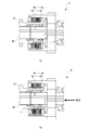
- FIG. 2 is a schematic configuration diagram of the clutch, (a) is a diagram showing a disconnected state, and (b) is a diagram showing a connected state.
- the clutch 4 is connected to the drive shaft 40 and the driven shaft 41 arranged to extend in the coaxial direction, a plurality of drive friction plates 42 connected to the drive shaft 40, and the driven shaft 41. And a plurality of driven friction plates 43.
- the drive shaft 40 is connected to the engine 3 described above, and rotates by the rotational driving force of the engine 3 to rotate the drive friction plate 42.
- the drive friction plate 42 is separated from the driven friction plate 43 and does not transmit rotation to the driven friction plate 43.
- the drive friction plate 42 contacts the driven friction plate 43 and transmits all of the rotational power to the driven friction plate 43. Further, in the half clutch state between the disconnected state and the connected state, the drive friction plate 42 transmits a part of the rotational power to the driven friction plate 43 while slipping via transmission oil (not shown).
- the driven friction plate 43 is rotated by the rotation transmission from the drive friction plate 42 and can rotate the driven shaft 41.
- the driven shaft 41 is connected to the propeller 2 through a gear or the like, and is configured such that the propeller 2 rotates when the driven shaft 41 rotates.
- Switching between the disconnected state, the half-clutch state, and the connected state can be performed by controlling the hydraulic pressure of a hydraulic pump (not shown) by the control device 9.
- the transmission 5 may be a known transmission that transmits the rotation of one shaft to the other shaft through a plurality of gears while changing the number of rotations (rotation speed).
- the transmission 5 is configured such that the rotation of the engine 3 can be changed and transmitted to the propeller 2 by adjusting the reduction ratio (or gear ratio). Further, the transmission 5 is configured to be able to switch between forward and reverse rotation directions of the propeller 2 by switching gears, thereby switching forward / reverse of the ship 10. Switching between forward / reverse can be performed by controlling the hydraulic pressure of a hydraulic pump (not shown) by the control device 9.
- the rotation speed detection device 6 is disposed in the vicinity of the rotation axis of the propeller 2 and can detect the rotation speed of the propeller 2.
- this rotation speed detection device 6 for example, a known tachometer that measures the rotation speed using a pulse signal can be used.
- the detection result of the rotation speed detection device 6 is transmitted to the control device 9.
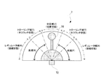
- FIG. 3 is a schematic configuration diagram of the input device.
- the input device 7 includes a lever 70 that can tilt in the left-right direction in FIG. 3 and a lever angle detection device 72 that detects the tilt angle of the lever 70.
- the state of the clutch 4 and the transmission 5 corresponding to the tilting of the lever 70 is displayed behind the lever 70.
- the lever 70 can be tilted left and right with the base as a rotation center, and the states of the clutch 4 and the transmission 5 can be switched according to the tilt angle.
- the front-rear and left-right directions in FIG. 3 are directions that are defined for convenience of explanation, and do not limit the directions in the implementation of the present invention.
- the state of the clutch 4 includes a disconnected state, a half-clutch state, and a connected state, which are classified as a neutral region (C), a trolling region (T), and a regulator region (R), respectively.
- the neutral zone (C) is assigned to a substantially central portion in FIG. 3
- a trolling zone (T) is assigned to the left and right sides thereof
- a regulator zone (R) is assigned to the left and right sides of the trolling zone (T).
- the state of the transmission 5 includes forward (F) and reverse (B), which are divided into right and left regions in FIG.
- the lever angle detection device 72 is configured to detect the input value of the input device 7 with respect to the clutch 4 and the transmission 5 by detecting the tilting (tilting) angle of the lever 70.
- a lever angle detecting device 72 a known gyroscope or a resistor can be used. The detection result by the lever angle detection device 72 is transmitted to the control device 9.
- each said state according to a lever angle can be detected because the lever angle detection apparatus 72 detects the tilt angle of the lever 70.
- FIG. For example, if the trolling region (T) is set to a region between 30 ° and 45 ° with respect to the vertical direction and the lever 70 is tilted 35 °, the lever angle detection device 72 detects this lever angle. Thus, the input value in the half-clutch state corresponding to the trolling region (T) can be detected. Then, this detection result is sent to the control device 9 as an input value in the input device 7.
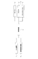
- FIG. 4 is a block diagram of a ship propulsion apparatus according to an embodiment of the present invention.
- the control device 9 is configured to be able to control the state of the clutch 4 and the transmission 5 in the reduction reverse rotation machine 8 and the operation of the engine 3 based on the input from the input device 7. Further, the control device 9 is configured to be able to control the state of the clutch 4 and the operation of the engine 3 based on the detection by the rotation speed detection device 6.
- FIG. 5 is a flowchart showing processing in the marine vessel propulsion apparatus.
- the clutch 4 is disengaged and the engine 3 is operated at the first engine speed. More specifically, the control device 9 starts the engine 3 by turning on a switch (not shown) while the clutch 4 is disengaged by holding the lever 70 of the input device 7 in the neutral region (C). (Step S1). At this time, the engine 3 operates in an idling state and operates at a minimum number of rotations (rotational speed). In the present embodiment, the engine speed in the idling state is set as the first engine speed.
- the first engine speed is, for example, 500 rpm.
- the input device 7 performs input. More specifically, the lever 70 of the input device 7 is tilted from the neutral region (C). When the ship 10 is moved forward, the lever 70 is tilted to the right in FIG. 3, and when the ship 10 is moved backward, the lever 70 is tilted to the left. When the lever 70 is tilted, the tilt angle (lever angle) is detected by the lever angle detection device 72, and the detection result is sent to the control device 9 as an input value of the input device 7. When receiving the input value in the input device 7, the control device 9 determines whether the input value is a value indicating forward or reverse, and based on the determination, determines the state of the transmission 5 by hydraulic control. Switching to forward or reverse (step S2).
- the control device 9 switches the gear of the transmission 5 to forward based on the input value (lever angle) at that time, while the lever 70 moves to the left When tilted to the reverse, switch the gear to reverse.
- the control device 9 determines whether or not the input value is a value indicating the half-clutch state, and indicates the half-clutch state. In this case, the state of the clutch 4 is switched from the disconnected state to the half-clutch state by hydraulic control.
- the lever 70 reaches the trolling region (T) by tilting, the lever angle at that position is an input value indicating a half-clutch state, and the control device 9 disengages the clutch 4 based on this input value. Set to the half clutch state.
- the control device 9 puts the clutch 4 in a half-clutch state and shifts the rotational speed of the engine 3 from the first engine rotational speed to the second engine rotational speed.
- the second engine speed is higher than the first engine speed and is a preset speed.
- the reduction ratio (gear ratio) of the reduction / reverse gear 8 including the clutch 4 is 1.0 and the first engine speed is 500 rpm
- the propeller speed is set to the connected state and the half-clutch state as described above.
- the second engine speed is set to about 560 rpm.
- the control device 9 controls the clutch 4 to be in the half-clutch state, and the engine 3 It operates at the second engine speed (step S3).
- the clutch 4 is in the half-clutch state, the rotational power of the engine 3 is transmitted to the propeller 2 via the clutch 4 and the propeller 2 starts to rotate.
- the input device 7 continues to input. More specifically, the lever 70 of the input device 7 is further tilted in the trolling region (T). Then, the tilt angle of the lever 70 is increased, and accordingly, the control device 9 further brings the drive friction plate 42 and the driven friction plate 43 of the clutch 4 closer by hydraulic pressure. As a result, the slip ratio of the clutch 4 decreases, and the rotation of the engine 3 is transmitted to the propeller 2 more reliably. Thereby, the rotation speed of the propeller 2 increases. At this time, the rotational speed of the propeller 2 is detected by the rotational speed detection device 6, and the detection result is sent to the control device 9. As shown in FIG.
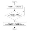
- the control device 9 determines whether or not the detection result has reached the target propeller rotation speed, and the rotation speed of the propeller 2 is determined. If the target engine speed has been reached, the engine 3 is shifted from the second engine speed to the above-mentioned first engine speed (step S4). At this time, the target propeller rotational speed can be changed as appropriate, but it is preferable to set the rotational speed equal to the rotational speed of the propeller 2 when the clutch 4 is in the connected state at the first engine rotational speed. For example, when the rotation speed of the propeller 2 is 500 rpm when the clutch 4 is in the connected state, the target propeller rotation speed is set to 500 rpm.
- the control device 9 determines whether or not the input value is a value indicating the connection state of the clutch 4. If the input value indicates the connection state, the control device 9 performs the clutch 4 by hydraulic control. Is switched from the half-clutch state to the connected state (step S5).
- the lever 70 reaches the regulator range (R) by tilting, the lever angle at that position is an input value indicating the connected state, and the control device 9 connects the clutch 4 based on this input value. Put it in a state.
- the clutch 4 is in the connected state, all of the rotational power of the engine 3 is transmitted to the propeller 2 via the clutch 4, and the propeller 2 rotates completely.
- the propeller speed can be changed almost linearly according to the tilt angle of the lever 70, and as a result, the ship 10 The speed can be controlled smoothly.
- the return from the second engine speed to the first engine speed is performed in the vicinity of the boundary between the trolling area (T) and the regulator area (R) in FIG. 3, and as a result, the trolling area (T). In substantially the entire region of, the second engine speed is obtained.
- the propeller rotation speed at this time is, for example, 500 rpm.
- the ship propulsion apparatus 1 propels the ship 10 by rotating the propeller 2 as described above.
- the stable half clutch state ( The rotational speed of the propeller 2 in the trolling region T) can be increased.
- the rotational speed of the engine 3 is changed to a rotational speed smaller than the second engine rotational speed, and the clutch 4 is changed from the half-clutch state to the connected state.
- the number and the propeller rotation speed in the connected state can be brought close to each other. More specifically, as shown in FIG.
- each component of the above-described ship propulsion device 1 is not particularly limited, and can be changed as appropriate.
- FIG. 9 is a schematic configuration diagram of an input device according to another embodiment of the present invention, in which (a) is a front view, (b) is a side view, and (c) is a top view. 9, the same components as those in FIG. 3 are denoted by the same reference numerals, and the description thereof is omitted.
- the lever 70 of the input device 7 is configured to be tiltable not only in the left-right direction but also in the front-rear direction (vertical direction in FIG. 9).
- a known joystick lever can be used.
- the input mechanism when the lever 70 is tilted back and forth is the same as the input mechanism when the lever 70 is tilted left and right, and the description thereof will be omitted. According to such a configuration, input can be performed by tilting the lever 70 forward and backward or left and right.
- the rotation speed of the propeller 2 when the rotation speed of the propeller 2 reaches the target rotation speed, the rotation speed of the engine 3 is returned from the second engine rotation speed to the first engine rotation speed. There is no need to return to the engine speed, and there is no particular limitation as long as the engine speed is smaller than the second engine speed. Therefore, instead of the first engine speed, another engine speed (third engine speed) smaller than the second engine speed can be set.
- the first engine speed can be appropriately changed according to the performance of the ship 10.
- the second engine speed is not particularly limited as long as it is higher than the first engine speed, and can be changed as appropriate.
- the configuration in which the clutch 4 is switched from the disconnected state to the connected state via the half-clutch state is described.
- the clutch 4 is switched from the connected state to the disconnected state, if the tilting speed of the lever 70 is fast, the clutch 4 may be switched without going through the half-clutch state.
- the clutch 4 in the half-clutch state may be hydraulically controlled based on the detection result of the rotational speed detection device 6.
- the present invention is not limited to this embodiment.
- the first engine speed related to the engine 3 is set to 500 rpm
- the reduction ratio of the transmission 5 is set to 2.0. Therefore, the rotation speed of the propeller 2 when the clutch 4 is in the connected state is 250 rpm (500 rpm / 2.0).
- the rotation of the propeller 2 is performed when the clutch 4 is in the half-clutch state and the slip ratio is near 0%.
- the number is preferably about 250 rpm.
- the clutch 4 can temporarily transmit the rotation of the engine 3 to the propeller 2.
- the propeller rotational speed at that time is 250 rpm (500 rpm / 2.0 ⁇ 100%).
- the clutch 4 becomes difficult to transmit the rotation of the engine 3 to the propeller 2 when the slip ratio is 0% to 10%, and only about 90% of the rotation of the engine 3 can be transmitted to the propeller 2 in some cases. is there. Therefore, in this case, since the clutch 4 can transmit only 90% of the rotation, the rotation speed of the propeller is 225 rpm (500 rpm / 2.0 ⁇ 90%).
- the second engine speed of the engine 3 is set to 560 rpm, and when the clutch 4 is in the half-clutch state, the engine speed is changed from the first engine speed (500 rpm) to the second engine speed.
- the rotation speed was increased to 560 rpm.
- the propeller speed can be increased, and the propeller speed is reduced to about 250 rpm (560 rpm) in the half-clutch state where the slip rate is 0%. /2.0 ⁇ 90%).
- the engine 3 was returned to the first engine speed (500 rpm), and the clutch 4 was brought into a connected state.
- the rotation speed of the propeller 2 is 250 rpm (500 rpm / 2.0).
- the rotation speed of the propeller in the half-clutch state (about 250 rpm) at the slip rate of 0% is made closer to the rotation speed of the propeller (250 rpm) in the connected state. Can do.
Landscapes
- Engineering & Computer Science (AREA)
- General Engineering & Computer Science (AREA)
- Mechanical Engineering (AREA)
- Chemical & Material Sciences (AREA)
- Combustion & Propulsion (AREA)
- Ocean & Marine Engineering (AREA)
- Physics & Mathematics (AREA)
- Fluid Mechanics (AREA)
- Hydraulic Clutches, Magnetic Clutches, Fluid Clutches, And Fluid Joints (AREA)
- Control Of Transmission Device (AREA)
- Control Of Vehicle Engines Or Engines For Specific Uses (AREA)
Abstract
船舶をスムーズに発進させることができる船舶推進装置を提供する。 制御装置9が、クラッチ4が切断状態のときはエンジン3を第1のエンジン回転数で作動させ、入力装置7における入力に基づいて、クラッチ4を切断状態から半クラッチ状態にすると共にエンジン3を第1のエンジン回転数より大きい第2のエンジン回転数で作動させ、回転数検知装置6の検知に基づいて、エンジン3を第2のエンジン回転数より小さいエンジン回転数で作動させ、入力装置7における入力に基づいて、クラッチ4を半クラッチ状態から接続状態にする船舶推進装置1である。
Description
本発明は、船舶を推進するための船舶推進装置に関する。
従来、船舶を推進するための船舶推進装置として、特許文献1に記載のような船舶推進装置が知られていた。図10は、従来の船舶推進装置の概略構成図である。図10に示すように、この船舶推進装置100は、船舶を推進するためのプロペラ101と、プロペラ101を回転させるためのエンジン102と、エンジン102の回転をプロペラ101に伝達可能な減速逆転機103と、を備えている。減速逆転機103は、図示しないクラッチを内部に備えている。また、船舶推進装置100は、減速逆転機103内のクラッチの状態を入力可能な入力装置104と、クラッチの状態およびエンジン102の作動を制御する制御装置105と、を備えている。
このような構成を備える船舶推進装置100により船舶を推進するときは、まず、減速逆転機103内のクラッチが切断されている状態で、図示しないスイッチをオンにすることにより、制御装置105がエンジン102を作動させる。次にエンジン102が作動している状態で、減速逆転機103のクラッチを半クラッチ状態にするように入力装置104で入力することにより、制御装置105がクラッチを半クラッチ状態にする。これにより、エンジン102の回転が減速逆転機103のクラッチを介してプロペラ101に伝達されるので、プロペラ101が回転し始める。その後、エンジン102が作動すると共にクラッチが半クラッチ状態になっている状態で、さらに、クラッチを接続状態にするように入力装置104で入力することにより、制御装置105がクラッチを接続状態にする。これにより、クラッチが完全に連結され、エンジン102の回転が全てクラッチを介してプロペラ101に伝達される。その結果、プロペラ101が完全に回転する。このように、減速逆転機103のクラッチを切断状態から半クラッチ状態を経て接続状態にすることにより、プロペラ101を回転させることができ、これにより船舶を推進することができる。
しかし、上述のような船舶推進装置100では、減速逆転機103のクラッチを半クラッチ状態から接続状態に切り替えるときに、プロペラ101の回転数が急激に増大してしまうことがある。これは、減速逆転機103のクラッチが半クラッチ状態のときは、エンジン102の回転の一部がプロペラ101に伝達されており、エンジン102の回転の全てがプロペラ101に伝達されているのではないので、クラッチが接続状態のときと比較してプロペラ101が低速で回転しているが、半クラッチ状態と接続状態との境界付近では安定した半クラッチ状態が得られないため、この境界付近ではプロペラ101の回転が急激に増大することがあるからである。その結果、プロペラ101の回転をスムーズにコントロールすることが難しく、船舶速度もスムーズに変更することが困難であった。よって、この点で改良の余地があった。
本発明は、上記問題を解決するためになされたものであって、船舶の速度をスムーズにコントロールすることができる船舶推進装置の提供を目的とする。
本発明は、上記課題を解決するための船舶推進装置であって、船舶を推進するためのプロペラと、前記プロペラを回転させるためのエンジンと、前記エンジンの回転を前記プロペラに伝達可能なクラッチと、前記クラッチの状態を入力可能な入力手段と、前記プロペラの回転数を検知する回転数検知手段と、前記エンジンの作動および前記クラッチの状態を制御する制御手段と、を備え、前記制御手段は、前記クラッチが切断状態のときは前記エンジンを第1のエンジン回転数で作動させ、前記入力手段における入力に基づいて、前記クラッチを切断状態から半クラッチ状態にすると共に前記エンジンを前記第1のエンジン回転数より大きい第2のエンジン回転数で作動させ、前記回転数検知手段の検知に基づいて、前記エンジンを前記第2のエンジン回転数より小さいエンジン回転数で作動させ、前記入力手段における入力に基づいて、前記クラッチを半クラッチ状態から接続状態にする船舶推進装置である。
このような構成によれば、クラッチが半クラッチ状態のときにエンジンの回転数を第1のエンジン回転数より大きい第2のエンジン回転数にするので、半クラッチ状態におけるプロペラの回転数を増大させることができる。そして、一旦プロペラ回転数を増大させた状態で、エンジンの回転数を第2のエンジン回転数より小さい回転数にし、クラッチを半クラッチ状態から接続状態にするので、半クラッチ状態におけるプロペラ回転数と接続状態におけるプロペラ回転数とを接近させることができる。すなわち、エンジン回転数を一旦増大させることなくクラッチを接続状態にすると、半クラッチ状態から接続状態にするときにプロペラ回転数が急激に増大してしまい、急な船舶の速度変化が生じてしまう。しかしながら、本発明によれば、半クラッチ状態から接続状態にするとき、両状態におけるプロペラ回転数を接近させることができるので、プロペラ回転数が瞬間的に急増するのを防ぐことができる。その結果、プロペラ回転数がスムーズに増大してゆくので、船舶の速度をスムーズにコントロールすることができる。このような構成は、船舶を沖で定点保持するときや岸に停留させるときに半クラッチ状態を利用するので特に有効である。
また、従来は、特許文献1に記載のように、クラッチの油圧を制御することによりプロペラの回転数を制御する構成はあったが、これでは、プロペラの回転の元になるエンジンの回転数を大きくしていないので、プロペラ回転数を大きくしようとしても限界があった。そこで、本願の発明者は、半クラッチの状態において、エンジンの回転数を大きくすることによりプロペラの回転数を大きくするという知見を見出した。また、特許文献1に記載のクラッチの油圧を制御することによりプロペラの回転数を制御する構成に対し、半クラッチ状態のときのみエンジンの回転数を大きくすることによりプロペラ回転数を大きくするという知見を適用することは、制御対象が異なるので容易なことではなかった。本発明は、このような知見などに基づくものである。
また、上記の船舶推進装置において、前記制御手段は、前記回転数検知手段の検知に基づいて、前記エンジンの回転数を前記第2のエンジン回転数から前記第1のエンジン回転数に戻すことができる。
本発明に係る船舶推進装置によれば、船舶をスムーズに発進させることができる。
以下、本発明の実施形態について添付図面を参照して説明する。図1は、本発明の一実施形態に係る船舶推進装置の全体図である。図1に示すように、船舶推進装置1は、船舶10に設置されており、船舶10を推進するためのプロペラ2と、プロペラ2を回転させるためのエンジン3と、エンジン3の回転をプロペラ2に伝達可能なクラッチ4及びトランスミッション5を有する減速逆転機8と、プロペラ2の回転数を検知する回転数検知装置6とを備えている。また、船舶推進装置1は、クラッチ4及びトランスミッション5の状態を入力可能な入力装置7を備えている。また、船舶推進装置1は、エンジン3の作動、並びに、クラッチ4及びトランスミッション5の状態を制御する制御装置9を備えている。
船舶10は、人や物をのせて航海をする公知のボートやクルーザーなどである。プロペラ2は、船舶10の船尾から後方へ延びるプロペラ回転軸と、当該プロペラ回転軸の軸方向後端部に放射状に固定された複数の羽根とを備えており、回転による推進力によって船舶10を前進または後進させることができる。また、エンジン3としては、回転駆動力を発生させるものであれば特に限定されず、一般的な船舶に用いられる公知の発動機を用いることができる。このエンジン3は、図1では図示していない後述の駆動軸40を回転させることができる。また、エンジン3の回転数(回転速度)は、電気制御等により変速可能に構成されている。
クラッチ4は、一方の軸から他方の軸へ回転を断続して伝達する公知の回転伝達装置を用いることができる。本実施形態では、クラッチ4として、対向する摩擦板の摩擦力により回転を伝達する公知の摩擦クラッチを用いており、対向する摩擦板の離間距離を油圧の増減によって調節することにより、切断状態、半クラッチ状態及び接続状態を相互に切り替えることができる。切断状態とは、対向する摩擦板が相互に切り離されており、一方の軸の回転動力が他方の軸へ伝達されていない状態である。また、半クラッチ状態とは、切断状態と接続状態との間の状態であり、対向する摩擦板が互いにスリップしながら接続されており、一方の軸の回転動力の一部のみが他方の軸へ伝達される状態である。また、接続状態とは、対向する摩擦板が相互に結合しており、一方の軸の回転動力の全てが他方の軸へ伝達される状態である。
図2は、クラッチの概略構成図であり、(a)は切断状態を示す図であり、(b)は接続状態を示す図である。図2に示すように、クラッチ4は、同軸方向に延びるように配置された駆動軸40及び従動軸41と、駆動軸40に連結された複数の駆動摩擦板42と、従動軸41に連結された複数の従動摩擦板43とを備えている。駆動軸40は、前述のエンジン3に接続されており、エンジン3の回転駆動力により回転し、駆動摩擦板42を回転させる。駆動摩擦板42は、図2(a)に示す切断状態では、従動摩擦板43と切り離されており、従動摩擦板43に回転を伝達しない。また、図2(b)に示す接続状態では、駆動摩擦板42は従動摩擦板43に当接し、回転動力の全てを従動摩擦板43に伝達する。また、切断状態と接続状態との間の半クラッチ状態では、駆動摩擦板42は図示しない伝達オイルを介してスリップしながら従動摩擦板43に回転動力の一部を伝達する。従動摩擦板43は、駆動摩擦板42からの回転伝達により回転し、従動軸41を回転させることができる。従動軸41は、ギヤなどを介してプロペラ2に接続されており、従動軸41が回転することによりプロペラ2が回転するように構成されている。
切断状態、半クラッチ状態、接続状態をそれぞれ切り替えるときは、制御装置9によって図示しない油圧ポンプの油圧を制御することにより行うことができる。
トランスミッション5は、複数のギヤを介して一方の軸の回転をその回転数(回転速度)を変えて他方の軸へ伝達する公知の変速装置を用いることができる。このトランスミッション5は、減速比(または、ギヤ比)を調節することによりエンジン3の回転を変速してプロペラ2に伝達できるように構成されている。また、トランスミッション5は、ギヤを切り替えることによりプロペラ2の回転方向を正逆切り替えることができ、これにより、船舶10の前進/後進を切り替えることができるように構成されている。前進/後進を切り替えるときは、制御装置9によって図示しない油圧ポンプの油圧を制御することにより行うことができる。
回転数検知装置6は、プロペラ2の回転軸近傍に配置されており、プロペラ2の回転数を検知することができる。この回転数検知装置6としては、例えば、パルス信号を用いて回転数を計測する公知のタコメーターなどを用いることができる。回転数検知装置6の検知結果は、制御装置9へ送信される。
図3は、入力装置の概略構成図である。図3に示すように、入力装置7は、図3の左右方向に傾動可能なレバー70と、このレバー70の傾動角度を検知するレバー角度検知装置72とを備えている。また、図3では、レバー70の背後に、レバー70の傾動に対応するクラッチ4およびトランスミッション5の状態が表示されている。
レバー70は、基部を回動中心として左右に傾動可能であり、その傾動角度に応じて、クラッチ4およびトランスミッション5の状態を切り替えることができる。なお、図3の前後左右の方向は説明のために便宜的に規定する方向であり、本発明の実施における方向を限定するものではない。
クラッチ4の状態としては、切断状態、半クラッチ状態、及び、接続状態があり、これらがそれぞれ、中立域(C)、トローリング域(T)、及び、レギュレータ域(R)として区分されている。中立域(C)は図3における略中央部に割り当てられ、その左右両側にトローリング域(T)が割り当てられ、さらにトローリング域(T)の左右両側にレギュレータ域(R)が割り当てられている。また、トランスミッション5の状態としては、前進(F)および後進(B)があり、これらがそれぞれ、図3における右左の領域に区分されている。
レバー角度検知装置72は、レバー70の傾動(傾斜)角度を検知することにより、クラッチ4及びトランスミッション5に対する入力装置7の入力値を検知できるように構成されている。このようなレバー角度検知装置72としては、公知のジャイロスコープや抵抗を用いることができる。レバー角度検知装置72による検知結果は、制御装置9へ送信される。
このような入力装置7では、レバー70を中立域(C)で保持するとクラッチ4が切断状態になり、レバー70を傾動させてトローリング域(T)で保持するとクラッチ4が半クラッチ状態になり、さらにレバー70を傾動させてレギュレータ域(R)で保持するとクラッチ4が接続状態になるように予め設定されている。また、レバー70を右方向に傾動させると船舶10が前進するようにトランスミッション5のギヤが噛み合い、一方、レバー70を左方向に傾動させると船舶10が後進するようにトランスミッション5のギヤが噛み合うように予め設定されている。そして、レバー70の傾動角度をレバー角度検知装置72が検知することにより、レバー角度に応じた上記の各状態を検知可能なように構成されている。例えば、トローリング域(T)が鉛直方向に対して30°~45°の間の領域に設定されており、レバー70を35°傾動させたとすると、このレバー角度をレバー角度検知装置72が検知することにより、トローリング域(T)に対応する半クラッチ状態の入力値を検知可能なように構成されている。そして、この検知結果が、入力装置7における入力値として制御装置9へ送られる。
図4は、本発明の一実施形態に係る船舶推進装置のブロック図である。図4に示すように、制御装置9は、入力装置7における入力に基づいて、減速逆転機8内のクラッチ4及びトランスミッション5の状態、並びに、エンジン3の作動を制御可能に構成されている。また、制御装置9は、回転数検知装置6の検知に基づいて、クラッチ4の状態およびエンジン3の作動を制御可能に構成されている。
次に、以上のような構成を備える船舶推進装置1を用いて船舶10を推進する方法について説明する。図5は、船舶推進装置における処理を示すフローチャートである。
図5に示すように、船舶1を推進するときは、まず、クラッチ4を切断状態として、エンジン3を第1のエンジン回転数で作動させる。より具体的には、入力装置7のレバー70を中立域(C)に保持することによりクラッチ4を切断した状態で、図示しないスイッチをオンにすることにより、制御装置9がエンジン3を始動する(ステップS1)。このとき、エンジン3は、アイドリング状態で作動し、最低限の回転数(回転速度)で作動している。本実施形態では、このアイドリング状態でのエンジン回転数を第1のエンジン回転数とする。第1のエンジン回転数は、例えば、500rpmである。
続いて、入力装置7において入力を行う。より具体的には、入力装置7のレバー70を中立域(C)から傾動させてゆく。船舶10を前進させるときは、図3においてレバー70を右方向へ傾動させ、後進させるときはレバー70を左方向へ傾動させる。レバー70を傾動させると、この傾動角度(レバー角度)をレバー角度検知装置72が検知し、その検知結果が入力装置7の入力値として制御装置9へ送られる。制御装置9は、入力装置7における入力値を受信すると、入力値が前進を示す値であるか後進を示す値であるかを判断し、その判断に基づいて、油圧制御によりトランスミッション5の状態を前進または後進に切り替える(ステップS2)。本実施形態では、制御装置9は、レバー70が右方向へ傾動したときは、そのときの入力値(レバー角度)に基づいて、トランスミッション5のギヤを前進に切り替え、一方、レバー70が左方向へ傾動したときは、ギヤを後進に切り替える。
また、制御装置9は、図6に示すように、入力装置7における入力値を受信すると、入力値が半クラッチ状態を示す値であるか否かを判断し、半クラッチ状態を示すものである場合は、油圧制御によりクラッチ4の状態を切断状態から半クラッチ状態に切り替える。本実施形態では、レバー70が傾動によりトローリング域(T)に到達したとき、その位置でのレバー角度が半クラッチ状態を示す入力値であり、この入力値に基づいて制御装置9がクラッチ4を半クラッチ状態にする。また、このとき、制御装置9は、クラッチ4を半クラッチ状態にすると共に、エンジン3の回転数を第1のエンジン回転数から第2のエンジン回転数に変速する。この第2のエンジン回転数は、第1のエンジン回転数より大きな回転数であり、予め設定可能な回転数である。例えば、クラッチ4を備えた減速逆転機8の減速比(ギヤ比)が1.0で、第1のエンジン回転数が500rpmの場合、プロペラ回転数が前述のように接続状態と半クラッチ状態との境界付近である450~500rpm(スリップ率で0~10%の範囲)が安定して得られない場合は、第2のエンジン回転数を約560rpmとする。この場合、第2のエンジン回転数では、同様に0~10%のスリップ率が安定しないと想定しても、上限として504rpm(=560×0.9)までは安定した半クラッチ状態が得られることになる。
したがって、レバー70がトローリング域(T)に到達することにより入力装置7の入力値が半クラッチ状態を示す値になると、制御装置9の制御により、クラッチ4は半クラッチ状態になり、エンジン3は第2のエンジン回転数で作動する(ステップS3)。クラッチ4が半クラッチ状態になると、エンジン3の回転動力がクラッチ4を介してプロペラ2に伝達され、プロペラ2が回転し始める。
その後、引き続き、入力装置7において入力を行う。より具体的には、入力装置7のレバー70をトローリング域(T)において更に傾動させてゆく。そうすると、レバー70の傾動角度が増大してゆき、これに伴って、制御装置9がクラッチ4の駆動摩擦板42と従動摩擦板43とを油圧により更に接近させてゆく。その結果、クラッチ4のスリップ率が低下してゆき、エンジン3の回転がより確実にプロペラ2に伝達される。これにより、プロペラ2の回転数が増大してゆく。このとき、プロペラ2の回転数は、回転数検知装置6により検知されており、その検知結果が制御装置9へ送られる。制御装置9は、図7に示すように、回転数検知装置6における検知結果を受信すると、その検知結果が目標のプロペラ回転数に到達しているか否かを判断し、プロペラ2の回転数が目標の回転数に到達している場合は、エンジン3の回転数を第2のエンジン回転数から上述の第1のエンジン回転数に戻すように変速する(ステップS4)。このとき、目標のプロペラ回転数は、適宜変更可能であるが、クラッチ4が第1のエンジン回転数で接続状態であるときのプロペラ2の回転数と同じ回転数にすることが好ましい。例えば、クラッチ4が接続状態であるときのプロペラ2の回転数が500rpmになる場合には、目標のプロペラ回転数を500rpmに設定する。
さらにその後、入力装置7のレバー70を傾動させると、レバー70の傾動角度がレバー角度検知装置72によって検知され、検知結果が入力装置7の入力値として制御装置9へ送られる。制御装置9は、入力装置7における入力値を受信すると、入力値がクラッチ4の接続状態を示す値であるか否かを判断し、接続状態を示すものである場合は、油圧制御によりクラッチ4の状態を半クラッチ状態から接続状態に切り替える(ステップS5)。本実施形態では、レバー70が傾動によりレギュレータ域(R)に到達したとき、その位置でのレバー角度が接続状態を示す入力値であり、この入力値に基づいて制御装置9がクラッチ4を接続状態にする。クラッチ4が接続状態になると、エンジン3の回転動力の全てがクラッチ4を介してプロペラ2に伝達され、プロペラ2が完全に回転する。
このように、エンジン回転数の切り替えと、半クラッチ状態から接続状態への切り替えとを行うことにより、レバー70の傾動角度に応じてプロペラ回転数をほぼ線形的に変更でき、結果として船舶10の速度をスムーズにコントロールすることができる。
なお、第2のエンジン回転数から第1のエンジン回転数に戻すのは、図3におけるトローリング域(T)とレギュレータ域(R)との境界付近で行われ、結果として、トローリング域(T)の略全域では、第2のエンジン回転数になる。
その後、クラッチ4が接続状態になると、エンジン3の回転動力の全てがクラッチ4を介してプロペラ2に伝達され、プロペラ2が完全に回転する。このときのプロペラ回転数は、例えば、500rpmである。
本発明に係る船舶推進装置1は、以上のようにしてプロペラ2を回転させることにより船舶10を推進する。このような船舶推進装置1によれば、クラッチ4が半クラッチ状態のときにエンジン3の回転数を第1のエンジン回転数より大きい第2のエンジン回転数にするので、安定した半クラッチ状態(トローリング域T)におけるプロペラ2の回転数を増大させることができる。そして、一旦プロペラ回転数を増大させた状態で、エンジン3の回転数を第2のエンジン回転数より小さい回転数にし、クラッチ4を半クラッチ状態から接続状態にするので、半クラッチ状態におけるプロペラ回転数と接続状態におけるプロペラ回転数とを接近させることができる。より詳細に説明すると、図8に示すように、レバー70がトローリング域(T)まで傾動したとき、つまり、クラッチ4が半クラッチ状態になるときに、エンジン3の回転数を変速せずに第1のエンジン回転数のまま維持すると、図中の符合Xで示すように、プロペラ2の回転数があまり増大しない。しかし、エンジン3の回転数を第1のエンジン回転数から第2のエンジン回転数に増大させると、図中の符号Yで示すように、プロペラ2の回転数が増大する。そうすると、クラッチ4が半クラッチ状態から接続状態に切り替わるとき(つまり、レバー70がトローリング域(T)からレギュレータ域(R)まで傾動するとき)、符号Zで示すように、半クラッチ状態のプロペラ回転数と接続状態のプロペラ回転数とを接近させることができる。これにより、クラッチ4を切り替えるときにプロペラ回転数が急増するのを防ぐことができる。その結果、プロペラ回転数がスムーズに増大してゆくので、船舶10をスムーズに発進させることができる。
以上、本発明の一実施形態について説明したが、本発明の具体的な態様は、上記実施形態に限定されるものではない。
例えば、上述した船舶推進装置1の各構成要素の配置構成は特に限定されず、適宜変更可能である。
また、上記実施形態では、入力装置7のレバー70は、左右に傾動する構成であったが、この構成に限定されるものではない。図9は、本発明の他の実施形態に係る入力装置の概略構成図であり、(a)は正面図、(b)は側面図、(c)は上面図である。図9において、図3と同様の構成部分については、同一の符号を付してその説明を省略する。図9に示すように、この入力装置7のレバー70は、左右だけでなく、前後方向(図9の上下方向)にも傾動可能に構成されている。このようなレバー70としては、公知のジョイスティックレバーを用いることができる。この入力装置7において、レバー70を前後に傾動させる場合の入力機構は、左右に傾動させる場合の入力機構と同様の構成なので、その説明を省略する。このような構成によれば、レバー70を前後又は左右に傾動させることにより入力を行うことができる。
また、上記実施形態では、プロペラ2の回転数が目標の回転数に到達したときにエンジン3の回転数を第2のエンジン回転数から第1のエンジン回転数に戻したが、必ずしも第1のエンジン回転数に戻す必要はなく、第2のエンジン回転数より小さいエンジン回転数にするのであれば特に限定されるものではない。したがって、第1のエンジン回転数に代えて、第2のエンジン回転数より小さい他のエンジン回転数(第3のエンジン回転数)にすることができる。
また、第1のエンジン回転数は、船舶10の性能に応じて適宜変更可能である。
また、第2のエンジン回転数は、第1のエンジン回転数より大きい回転数であれば特に限定されず、適宜変更可能である。
なお、上記実施形態では、クラッチ4を切断状態から半クラッチ状態を経由して接続状態にする構成について説明したが、船舶推進装置1の実施においては、必ずしも半クラッチ状態を経由させる必要はなく、切断状態からすぐに接続状態に切り替えることもできる。例えば、入力装置7のレバー70を傾動させるときに、予め設定された傾動速度より速い速度で傾動させた場合は、クラッチ4が半クラッチ状態を経由せずに、切断状態からすぐに接続状態に切り替わるようにしてもよい。また、これと同様に、クラッチ4を接続状態から切断状態にするときに、レバー70の傾動速度が速い場合は、半クラッチ状態を経由せずに切り替えるようにしてもよい。
また、入力装置7における入力値と半クラッチ状態におけるプロペラ回転数とを整合させるために、回転数検知装置6の検知結果に基づいて半クラッチ状態におけるクラッチ4を油圧制御してもよい。
本発明に係る船舶推進装置1を用いてプロペラ2を回転させる実施例を以下に示す。ただし、本発明が本実施例に限定されるものではない。この実施例に係る船舶推進装置1では、エンジン3に係る第1のエンジン回転数を500rpmとし、トランスミッション5の減速比を2.0とした。したがって、クラッチ4が接続状態であるときのプロペラ2の回転数は250rpm(500rpm/2.0)である。
この場合、半クラッチ状態でのプロペラ回転数と接続状態でのプロペラ回転数とを接近させる観点から、クラッチ4が半クラッチ状態であってスリップ率が0%近傍であるときに、プロペラ2の回転数が約250rpmになることが好ましい。
ところで、エンジン3が第1のエンジン回転数(500rpm)であり、クラッチ4のスリップ率が0%のとき、クラッチ4が仮にエンジン3の回転を100%プロペラ2に伝達することができるのであれば、そのときのプロペラ回転数は250rpm(500rpm/2.0×100%)となる。しかしながら、実際は、クラッチ4はスリップ率が0%~10%のときにエンジン3の回転をプロペラ2に伝達し難くなり、エンジン3の回転の約90%しかプロペラ2に伝達することができない場合がある。したがってこの場合は、クラッチ4が回転を90%しか伝達できないので、プロペラ回転数は225rpm(500rpm/2.0×90%)になる。
そこで、これを解決するために、エンジン3の第2のエンジン回転数を560rpmとし、クラッチ4が半クラッチ状態のときにエンジンの回転数を第1のエンジン回転数(500rpm)から第2のエンジン回転数(560rpm)に増大させた。これにより、クラッチ4がエンジン回転の90%しかプロペラ2に伝達しない場合であってもプロペラ回転数を増大させることができ、スリップ率0%の半クラッチ状態において、プロペラ回転数を約250rpm(560rpm/2.0×90%)にすることができる。
その後、エンジン3を第1のエンジン回転数(500rpm)に戻し、クラッチ4を接続状態にした。このとき、プロペラ2の回転数は250rpm(500rpm/2.0)である。
このように、本発明に係る船舶推進装置1によれば、スリップ率0%における半クラッチ状態でのプロペラ回転数(約250rpm)と、接続状態でのプロペラ回転数(250rpm)とを接近させることができる。
1 船舶推進装置
2 プロペラ
3 エンジン
4 クラッチ
5 トランスミッション
6 回転数検知装置
7 入力装置
9 制御装置
10 船舶
2 プロペラ
3 エンジン
4 クラッチ
5 トランスミッション
6 回転数検知装置
7 入力装置
9 制御装置
10 船舶
Claims (2)
- 船舶を推進するためのプロペラと、
前記プロペラを回転させるためのエンジンと、
前記エンジンの回転を前記プロペラに伝達可能なクラッチと、
前記クラッチの状態を入力可能な入力手段と、
前記プロペラの回転数を検知する回転数検知手段と、
前記エンジンの作動および前記クラッチの状態を制御する制御手段と、を備え、
前記制御手段は、前記クラッチが切断状態のときは前記エンジンを第1のエンジン回転数で作動させ、前記入力手段における入力に基づいて、前記クラッチを切断状態から半クラッチ状態にすると共に前記エンジンを前記第1のエンジン回転数より大きい第2のエンジン回転数で作動させ、前記回転数検知手段の検知に基づいて、前記エンジンを前記第2のエンジン回転数より小さいエンジン回転数で作動させ、前記入力手段における入力に基づいて、前記クラッチを半クラッチ状態から接続状態にする船舶推進装置。 - 前記制御手段は、前記回転数検知手段の検知に基づいて、前記エンジンの回転数を前記第2のエンジン回転数から前記第1のエンジン回転数に戻す請求項1に記載の船舶推進装置。
Priority Applications (2)
| Application Number | Priority Date | Filing Date | Title |
|---|---|---|---|
| CN201180052236.4A CN103189274B (zh) | 2010-10-27 | 2011-10-13 | 船舶推进装置 |
| US13/814,516 US8882550B2 (en) | 2010-10-27 | 2011-10-13 | Ship propulsion device |
Applications Claiming Priority (2)
| Application Number | Priority Date | Filing Date | Title |
|---|---|---|---|
| JP2010-241233 | 2010-10-27 | ||
| JP2010241233A JP5634213B2 (ja) | 2010-10-27 | 2010-10-27 | 船舶推進装置 |
Publications (1)
| Publication Number | Publication Date |
|---|---|
| WO2012056894A1 true WO2012056894A1 (ja) | 2012-05-03 |
Family
ID=45993619
Family Applications (1)
| Application Number | Title | Priority Date | Filing Date |
|---|---|---|---|
| PCT/JP2011/073537 Ceased WO2012056894A1 (ja) | 2010-10-27 | 2011-10-13 | 船舶推進装置 |
Country Status (4)
| Country | Link |
|---|---|
| US (1) | US8882550B2 (ja) |
| JP (1) | JP5634213B2 (ja) |
| CN (1) | CN103189274B (ja) |
| WO (1) | WO2012056894A1 (ja) |
Families Citing this family (7)
| Publication number | Priority date | Publication date | Assignee | Title |
|---|---|---|---|---|
| GB2517753A (en) * | 2013-08-30 | 2015-03-04 | Ford Global Tech Llc | A method for limiting the amount of energy dissipated in a friction clutch during engagement of the clutch |
| US9841067B1 (en) * | 2014-06-06 | 2017-12-12 | Logan Clutch Corporation | Clutch assembly and system |
| KR101757667B1 (ko) * | 2016-09-20 | 2017-07-14 | 한화테크윈 주식회사 | 수상조향장치 |
| KR101976322B1 (ko) * | 2018-05-11 | 2019-05-07 | 김문규 | 워터제트 추진식 보트의 클러치 |
| KR101890094B1 (ko) * | 2018-05-11 | 2018-08-20 | 김문규 | 클러치가 설치되는 보트 |
| CN111874199A (zh) * | 2020-08-10 | 2020-11-03 | 滕秀峰 | 低转速输出船用挂桨机 |
| KR102577344B1 (ko) * | 2021-09-24 | 2023-09-12 | 주식회사 디에이치오션 | 다이버 추진체 |
Citations (2)
| Publication number | Priority date | Publication date | Assignee | Title |
|---|---|---|---|---|
| JPH0251623A (ja) * | 1988-08-10 | 1990-02-21 | Yanmar Diesel Engine Co Ltd | 舶用二段減速クラッチの自動制御装置 |
| JP2009202778A (ja) * | 2008-02-28 | 2009-09-10 | Yamaha Motor Co Ltd | 船舶用推進システム |
Family Cites Families (12)
| Publication number | Priority date | Publication date | Assignee | Title |
|---|---|---|---|---|
| JPS61135899A (ja) * | 1984-12-06 | 1986-06-23 | Yanmar Diesel Engine Co Ltd | 船舶のトロ−リング装置 |
| WO1991016235A2 (de) * | 1990-04-14 | 1991-10-31 | Zahnradfabrik Friedrichshafen Ag | Steuersystem zum betreiben einer antriebsanlage eines schiffes |
| US6443286B1 (en) * | 2001-01-18 | 2002-09-03 | Twin Disc, Incorporated | Modulatable power transmission clutch and a marine transmission |
| JP3568517B2 (ja) | 2002-06-07 | 2004-09-22 | ヤンマー株式会社 | 舶用減速逆転機の油圧制御機構 |
| US8521348B1 (en) * | 2004-02-11 | 2013-08-27 | Econtrols, Inc. | Watercraft speed control device |
| JP4666152B2 (ja) * | 2005-07-20 | 2011-04-06 | トヨタ自動車株式会社 | 船艇の操船装置 |
| JP2008069646A (ja) * | 2006-09-12 | 2008-03-27 | Yamaha Marine Co Ltd | 船舶推進機およびその運転方法 |
| JP2008151230A (ja) * | 2006-12-15 | 2008-07-03 | Hitachi Ltd | 自動変速機の制御装置および制御方法 |
| JP4979371B2 (ja) * | 2006-12-26 | 2012-07-18 | ヤマハ発動機株式会社 | 船舶推進装置の制御装置 |
| DE102008025480B3 (de) * | 2008-05-27 | 2009-12-24 | Robert Bosch Gmbh | Steuereinrichtung und Verfahren zur Beeinflussung der Motordrehzahl sowie des Schlupfgrads einer Kupplung eines Schiffsantriebs |
| JP5237152B2 (ja) * | 2009-02-24 | 2013-07-17 | ヤンマー株式会社 | エンジン制御装置 |
| JP5473464B2 (ja) * | 2009-08-07 | 2014-04-16 | ヤンマー株式会社 | 船舶のアウトドライブ装置 |
-
2010
- 2010-10-27 JP JP2010241233A patent/JP5634213B2/ja active Active
-
2011
- 2011-10-13 WO PCT/JP2011/073537 patent/WO2012056894A1/ja not_active Ceased
- 2011-10-13 CN CN201180052236.4A patent/CN103189274B/zh active Active
- 2011-10-13 US US13/814,516 patent/US8882550B2/en not_active Expired - Fee Related
Patent Citations (2)
| Publication number | Priority date | Publication date | Assignee | Title |
|---|---|---|---|---|
| JPH0251623A (ja) * | 1988-08-10 | 1990-02-21 | Yanmar Diesel Engine Co Ltd | 舶用二段減速クラッチの自動制御装置 |
| JP2009202778A (ja) * | 2008-02-28 | 2009-09-10 | Yamaha Motor Co Ltd | 船舶用推進システム |
Also Published As
| Publication number | Publication date |
|---|---|
| JP2012091698A (ja) | 2012-05-17 |
| US20130172149A1 (en) | 2013-07-04 |
| CN103189274B (zh) | 2015-10-07 |
| CN103189274A (zh) | 2013-07-03 |
| US8882550B2 (en) | 2014-11-11 |
| JP5634213B2 (ja) | 2014-12-03 |
Similar Documents
| Publication | Publication Date | Title |
|---|---|---|
| JP5634213B2 (ja) | 船舶推進装置 | |
| EP3613663B1 (en) | Hybrid type vessel propulsion apparatus | |
| JP6947686B2 (ja) | 船舶推進システム及び船舶 | |
| JP4809794B2 (ja) | 操船装置 | |
| EP3437986B1 (en) | Method of using a ship handling device | |
| US9156537B1 (en) | Watercraft propulsion system and propulsion machine controlling method | |
| JP2017178242A (ja) | 操船システム及び船舶 | |
| JP5176163B2 (ja) | 船舶用推進システム、その制御装置及び制御方法 | |
| US8156882B2 (en) | Marine vessel steering apparatus and marine vessel including the same | |
| JP2009243590A (ja) | 船舶推進装置 | |
| US8944868B2 (en) | Outboard motor | |
| JP5824255B2 (ja) | 船舶の操船装置 | |
| JP2017171263A (ja) | 船舶 | |
| JP2009241754A (ja) | 船舶推進装置 | |
| JP2022088152A (ja) | 操船システムおよび船舶 | |
| JP6397844B2 (ja) | 船舶 | |
| JP2009202778A (ja) | 船舶用推進システム | |
| JP2017171261A (ja) | 船舶 | |
| JP4731401B2 (ja) | 船舶用推進機の電子式遠隔制御装置及び船舶 | |
| KR101757667B1 (ko) | 수상조향장치 | |
| JP7171684B2 (ja) | 操船システムおよび船舶 | |
| JP2016159804A (ja) | 船舶 | |
| JP7132296B2 (ja) | 操船システムおよび船舶 | |
| JP2016159803A (ja) | 船舶 | |
| JP5667935B2 (ja) | 船舶の操船方法 |
Legal Events
| Date | Code | Title | Description |
|---|---|---|---|
| 121 | Ep: the epo has been informed by wipo that ep was designated in this application |
Ref document number: 11836033 Country of ref document: EP Kind code of ref document: A1 |
|
| DPE2 | Request for preliminary examination filed before expiration of 19th month from priority date (pct application filed from 20040101) | ||
| WWE | Wipo information: entry into national phase |
Ref document number: 13814516 Country of ref document: US |
|
| NENP | Non-entry into the national phase |
Ref country code: DE |
|
| 122 | Ep: pct application non-entry in european phase |
Ref document number: 11836033 Country of ref document: EP Kind code of ref document: A1 |