WO2012056802A1 - 電子内視鏡用プロセッサ及び電子内視鏡装置 - Google Patents
電子内視鏡用プロセッサ及び電子内視鏡装置 Download PDFInfo
- Publication number
- WO2012056802A1 WO2012056802A1 PCT/JP2011/069135 JP2011069135W WO2012056802A1 WO 2012056802 A1 WO2012056802 A1 WO 2012056802A1 JP 2011069135 W JP2011069135 W JP 2011069135W WO 2012056802 A1 WO2012056802 A1 WO 2012056802A1
- Authority
- WO
- WIPO (PCT)
- Prior art keywords
- image data
- mode
- electronic endoscope
- output
- input
- Prior art date
- Legal status (The legal status is an assumption and is not a legal conclusion. Google has not performed a legal analysis and makes no representation as to the accuracy of the status listed.)
- Ceased
Links
Images



Classifications
-
- A—HUMAN NECESSITIES
- A61—MEDICAL OR VETERINARY SCIENCE; HYGIENE
- A61B—DIAGNOSIS; SURGERY; IDENTIFICATION
- A61B1/00—Instruments for performing medical examinations of the interior of cavities or tubes of the body by visual or photographical inspection, e.g. endoscopes; Illuminating arrangements therefor
- A61B1/04—Instruments for performing medical examinations of the interior of cavities or tubes of the body by visual or photographical inspection, e.g. endoscopes; Illuminating arrangements therefor combined with photographic or television appliances
- A61B1/05—Instruments for performing medical examinations of the interior of cavities or tubes of the body by visual or photographical inspection, e.g. endoscopes; Illuminating arrangements therefor combined with photographic or television appliances characterised by the image sensor, e.g. camera, being in the distal end portion
-
- A—HUMAN NECESSITIES
- A61—MEDICAL OR VETERINARY SCIENCE; HYGIENE
- A61B—DIAGNOSIS; SURGERY; IDENTIFICATION
- A61B1/00—Instruments for performing medical examinations of the interior of cavities or tubes of the body by visual or photographical inspection, e.g. endoscopes; Illuminating arrangements therefor
- A61B1/00002—Operational features of endoscopes
- A61B1/00004—Operational features of endoscopes characterised by electronic signal processing
- A61B1/00009—Operational features of endoscopes characterised by electronic signal processing of image signals during a use of endoscope
-
- G—PHYSICS
- G02—OPTICS
- G02B—OPTICAL ELEMENTS, SYSTEMS OR APPARATUS
- G02B23/00—Telescopes, e.g. binoculars; Periscopes; Instruments for viewing the inside of hollow bodies; Viewfinders; Optical aiming or sighting devices
- G02B23/24—Instruments or systems for viewing the inside of hollow bodies, e.g. fibrescopes
- G02B23/2476—Non-optical details, e.g. housings, mountings, supports
- G02B23/2484—Arrangements in relation to a camera or imaging device
-
- H—ELECTRICITY
- H04—ELECTRIC COMMUNICATION TECHNIQUE
- H04N—PICTORIAL COMMUNICATION, e.g. TELEVISION
- H04N1/00—Scanning, transmission or reproduction of documents or the like, e.g. facsimile transmission; Details thereof
- H04N1/21—Intermediate information storage
- H04N1/2166—Intermediate information storage for mass storage, e.g. in document filing systems
-
- H—ELECTRICITY
- H04—ELECTRIC COMMUNICATION TECHNIQUE
- H04N—PICTORIAL COMMUNICATION, e.g. TELEVISION
- H04N7/00—Television systems
- H04N7/18—Closed-circuit television [CCTV] systems, i.e. systems in which the video signal is not broadcast
- H04N7/183—Closed-circuit television [CCTV] systems, i.e. systems in which the video signal is not broadcast for receiving images from a single remote source
-
- H—ELECTRICITY
- H04—ELECTRIC COMMUNICATION TECHNIQUE
- H04N—PICTORIAL COMMUNICATION, e.g. TELEVISION
- H04N2201/00—Indexing scheme relating to scanning, transmission or reproduction of documents or the like, and to details thereof
- H04N2201/0077—Types of the still picture apparatus
- H04N2201/0079—Medical imaging device
Definitions
- the present invention relates to an electronic endoscope processor that processes a video signal from an electronic endoscope and displays the processed video signal on a monitor or the like, and an electronic endoscope apparatus including the electronic endoscope and the electronic endoscope processor. .
- the electronic endoscope apparatus includes an image pickup device at the tip, outputs an image signal of an image taken by the image pickup device, processes an image signal output from the electronic endoscope, and has a predetermined format.
- a video signal (for example, an NTSC video signal) and display it on a monitor or the like.
- the electronic endoscope processor usually displays an image captured by the electronic endoscope on a monitor as a moving image.
- the electronic endoscope processor also has a function of displaying a captured image on a monitor as a still image so that the observation site can be observed in more detail.
- the display of the still image is triggered by, for example, pressing an operation button provided in the electronic endoscope or the electronic endoscope processor. That is, the frame displayed on the monitor when the operation button is pressed or the image of the next frame continues to be displayed as a still image.
- the user of the electronic endoscope needs to press the operation button at an appropriate timing while checking the moving image displayed on the monitor.
- it is necessary to operate the electronic endoscope and press the operation button while checking the monitor it is not easy to obtain a desired still image due to a delay in the timing of pressing the operation button.
- the operation button is pressed while the observation site is moving, there is a problem that a still image in which blurring or color shift occurs is acquired.
- Patent Document 1 an electronic endoscope processor having a function described in Japanese Patent Publication JP3497231B (hereinafter referred to as Patent Document 1) has been proposed.
- the electronic endoscope processor described in Patent Document 1 is configured to store the latest plural frames of image data in a memory, and an operation (such as pressing an operation button) for acquiring a still image is performed. In this case, it is configured to select one with less blur and color misregistration from a plurality of frames of image data stored in the memory, and display this on the monitor as a still image.
- the image data Since the image data is not stored in the memory until the still image is displayed on the monitor after the operation is performed, the image data is stored in the memory again when it is necessary to retake the still image. There was a problem that the examination time was prolonged because it was necessary to wait until it was done.
- the present invention has been made to solve the above problems. That is, the present invention can easily recognize a lesion even when a difference between a moving image displayed on a monitor and an acquired still image is large, and can acquire a desired still image in a short time.
- An object is to provide a processor for an endoscope and an electronic endoscope apparatus.
- an electronic endoscope processor is an electronic endoscope processor that processes a video signal from an electronic endoscope and displays the image signal on a monitor.
- Image data generating means for generating image data
- first and second image storing means capable of storing image data of a plurality of frames, and each of the image data is compared with the image data of the previous frame to obtain a difference value.
- the difference value is monitored, and a plurality of images stored in the first or second image storage means are based on the difference value.
- the multiple image data stored in the first and second image storage means are output.
- One of the image data repeatedly into a video signal characterized in that switching to the second reproduction mode in which the output of the.
- the mode is switched to the second or third mode.
- the most recent image data stored in the first or second image storage means is rewound and continuously displayed, and then appropriate image data with less blur and color shift is automatically based on the difference value.
- the second image storage means includes the latest image data including an image captured by the electronic endoscope during the second mode. Is stored, it is possible to acquire a still image in the third mode without waiting for accumulation of a new image.
- control means may compare the difference value with a predetermined threshold value and switch from the first reproduction mode to the second reproduction mode when the difference value becomes equal to or less than the predetermined threshold value.
- the first playback mode may be configured to convert a plurality of image data stored in the first and second image storage means into a video signal every plurality of frames and output the video signal.
- first mode when switching from the first mode to the second and third modes, frames are thinned out in the first playback mode, and still images are automatically acquired at a higher speed. It becomes possible to do.
- control unit receives an input of a control signal for switching from the first mode to the second or third mode, and when the control signal is input, it is switched to either the second mode or the third mode.
- a determination unit that determines whether to switch may be provided, and the control unit may be configured to switch from the first mode to the second or third mode based on a determination result by the determination unit.
- the determination means may be configured to determine to alternately switch between the second mode and the third mode every time a control signal is input.
- the determination unit switches from the first mode to the third mode only when a control signal is input within a predetermined time after switching from the second mode to the first mode. It is good also as a structure to perform.
- the predetermined time is, for example, a time corresponding to the number of image data that can be stored in the first image storage unit.
- the electronic endoscope processor of the present invention is an electronic endoscope processor that processes a video signal from the electronic endoscope and displays the processed video signal on a monitor.
- the image data generating means for generating the image data the first and second image storage means capable of storing image data of a plurality of frames, and the image data stored in the first and second image storage means are output, A motion detection unit that compares the output image data with the previous output image data to obtain a difference value, a signal processing unit that converts the image data into a video signal that can be displayed on a monitor, a signal processing unit, And control means for controlling the first and second image storage means.
- the control means sequentially converts the image data generated by the image data generation means into a video signal and outputs the video signal.
- a first mode in which image storage means is sequentially stored; and image data stored in the first image storage means is converted into a video signal and output, and image data generated by the image data generation means is The second mode to be stored in the image storage means, the image data stored in the second image storage means is converted into a video signal and output, and the image data generated by the image data generation means is sequentially converted to the first image. Control is performed in accordance with either the third mode stored in the storage means. In the second or third mode, the difference value is monitored, and the first or second image is based on the difference value. From the first reproduction mode in which a plurality of image data stored in the storage means is continuously converted into a video signal and output in order from the latest stored time, the first and second image recordings are output. Characterized in that switching to the second reproduction mode in which one repeat is converted to a video signal output of the plurality of image data stored in the unit.
- An electronic endoscope apparatus is an electronic endoscope apparatus including any one of the above-described electronic endoscope processors and an electronic endoscope connected to the electronic endoscope processor.
- first input unit and the second input unit may be the same.
- FIG. 1 is a block diagram of an electronic endoscope apparatus according to the first embodiment of the present invention.
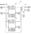
- FIG. 2 is a block diagram showing a configuration of a frame memory built in the electronic endoscope processor according to the first embodiment of the present invention.
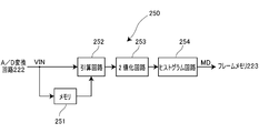
- FIG. 3 is a block diagram showing a configuration of a motion detection circuit built in the electronic endoscope processor according to the first embodiment of the present invention.
- FIG. 4 is a block diagram showing a configuration of a timing generator built in the electronic endoscope processor according to the first embodiment of the present invention.
- FIG. 5 is a timing chart for explaining an image storage / reproduction operation executed by the electronic endoscope apparatus according to the first embodiment of the present invention.
- FIG. 6 is a block diagram of an electronic endoscope apparatus according to the second embodiment of the present invention.
- FIG. 7 is a block diagram showing a configuration of a frame memory built in the electronic endoscope processor according to the second embodiment of the present invention.
- FIG. 8 is a block diagram showing a configuration of a motion detection circuit incorporated in the electronic endoscope processor according to the second embodiment of the present invention.
- FIG. 1 is a block diagram of an electronic endoscope apparatus 1 according to the first embodiment of the present invention.
- the electronic endoscope apparatus 1 according to the present embodiment includes an electronic endoscope 100, an electronic endoscope processor 200, and a monitor 300.
- an objective lens 121 and an image sensor 120 are incorporated.
- the objective lens 121 is disposed so as to form a subject image near the distal end portion 111 of the insertion tube on the light receiving surface of the image sensor 120.
- the image sensor 120 outputs a video signal corresponding to the image formed on the light receiving surface.
- the video signal is sent to the CCD process circuit 221 of the electronic endoscope processor 200 via a signal cable 123 inserted into the insertion tube 110.
- the image sensor 120 is controlled by timing pulses input to the image sensor 120 from a CCD drive circuit (not shown) built in the connector unit 150 of the electronic endoscope 100.
- the timing pulse output timing by the CCD drive circuit is controlled by a microcomputer (not shown) built in the connector unit 150.
- FIG. 1 for convenience of explanation, the electronic endoscope 100 and the electronic endoscope processor 200 are illustrated separately from each other. However, when the electronic endoscope 100 is used, the electronic endoscope 100 is The connector 150 is electrically and optically connected to the electronic endoscope processor 200.
- the electronic endoscope processor 200 includes a CCD process circuit 221, an A / D conversion circuit 222, a frame memory 223, a video process circuit 224, a timing generator 225, a CPU 210, a switch 240, a lighting device 230, and a motion detection circuit 250.
- the CCD process circuit 221 performs noise removal processing, amplification processing, and the like on the video signal input from the image sensor 120 and sends it to the A / D conversion circuit 222.
- the A / D conversion circuit 222 converts the analog video signal received from the CCD process circuit 221 into digital image data, and outputs the digital image data to the frame memory 223 and the motion detection circuit 250.
- the motion detection circuit 250 detects the motion amount MD of the subject included in each image data from the image data of each frame output from the A / D conversion circuit 222 and the image data of the immediately preceding frame, and the motion amount MD is detected.
- the data is output to the frame memory 223 (details will be described later).
- the frame memory 223 includes a memory capable of storing a plurality of frames of image data and a subject motion amount MD output from the motion detection circuit 250 (described later), and the image data and subject motion are controlled according to the control of the timing generator 225.
- the amount MD is stored, and the stored image data is output to the video process circuit 224.
- the subject motion amount MD stored in the frame memory 223 is output to the timing generator 225 in synchronization with the image data in accordance with the control of the timing generator 225.
- the video process circuit 224 converts the image data output from the frame memory 223 into a predetermined format video signal (for example, NTSC signal), and outputs the video signal to the monitor 300 connected to the electronic endoscope processor 200. Through the processing as described above, an image near the insertion tube distal end portion 111 of the electronic endoscope 100 is displayed on the monitor 300.
- the CPU 210 of the electronic endoscope processor 200 is connected to each component of the electronic endoscope processor 200 such as the switch 240 and the timing generator 225, and the electronic endoscope according to a program stored in a memory (not shown).
- the processor 200 and the electronic endoscope 100 are comprehensively controlled.
- the switch 240 is a user interface for the user to make various settings and instructions to the electronic endoscope processor 200, and is, for example, a freeze button for obtaining a still image.
- the CPU 210 sets or changes each control of the electronic endoscope processor 200 and the electronic endoscope 100 in accordance with an input from the switch 240.
- the scope button 140 of the electronic endoscope 100 and the CPU 210 are connected. Is configured so that the state of the scope button 140 can be monitored. That is, when the scope button 140 is pressed, a scope button input signal SB indicating that the scope button 140 has been pressed is sent to the CPU 210, and the CPU 210 determines whether or not the scope button 140 of the electronic endoscope 100 has been pressed. can do.
- the electronic endoscope processor 200 includes an illumination device 230 that generates illumination light for illuminating the vicinity of the insertion tube distal end portion 111 of the electronic endoscope 100.
- an illumination device 230 that generates illumination light for illuminating the vicinity of the insertion tube distal end portion 111 of the electronic endoscope 100.
- the electronic endoscope processor 200 includes a lamp 231, a diaphragm 232, and a condenser lens 233.
- a light guide 130 extends from the insertion tube 110 of the electronic endoscope 100 to the connector portion 150.
- the distal end portion 131 of the light guide 130 is disposed in the vicinity of the insertion tube distal end portion 111 of the electronic endoscope 100, and a light distribution lens (not shown) is disposed in the vicinity thereof.
- the lamp 231 built in the electronic endoscope processor 200 generates illumination light by supplying power from a lamp power supply circuit (not shown). Then, the generated illumination light enters the condenser lens 233 through the aperture 232.
- the light guide 130 protrudes from the connector unit 150 and is inserted into the electronic endoscope processor 200 when the electronic endoscope 100 is connected to the electronic endoscope processor 200. Yes.
- the base end portion 132 of the light guide 130 is disposed at a position where the illumination light condensed by the condenser lens 233 is incident.
- the illumination light generated by the lamp 231 enters the proximal end portion 132 of the light guide 130, reaches the distal end portion 131 through the light guide 130, passes through the light distribution lens, and passes through the insertion tube distal end portion 111. Illuminate nearby living tissue.
- the diaphragm 232 is controlled by the CPU 210. That is, the CPU 210 can control the diaphragm 232 to adjust the amount of illumination light incident on the base end portion 132 of the light guide 130 from the lamp 231 and change the brightness of the illumination light.
- FIG. 2 is a block diagram showing a configuration of the frame memory 223 built in the electronic endoscope processor 200 of the present embodiment.
- the frame memory 223 includes a first memory 223a, a second memory 223b, and a switch circuit 223c.
- the first memory 223a and the second memory 223b are, for example, ring-type memories configured by DRAMs.
- Digital image data output from the A / D conversion circuit 222 is sequentially input as input image data VIN, and a predetermined memory is used.
- the addresses are stored in order, such as frame 1, frame 2,.
- the first memory 223a and the second memory 223b are input with the motion amount MD of the subject output from the motion detection circuit 250 in synchronization with the input image data VIN, and the motion amount MD of each input image data VIN is HV1 (motion amount MD of frame 1), HV2 (motion amount MD of frame 2),...
- the first memory 223a and the second memory 223b of the present embodiment are configured to be able to store image data and motion amount MD for 240 frames, respectively.
- the first memory 223a and the second memory 223b are connected to the timing generator 225, respectively.
- the write address WA and the first memory read address RA1 are input to the first memory 223a, and the second memory 223b is input to the second memory 223b.
- the write address WA and the second memory read address RA2 are input.
- the write address WA is data representing addresses (addresses) on the first memory 223a and the second memory 223b that store the input image data VIN and the motion amount MD thereof.
- the write address WA is the same as the first memory 223a.
- a common write address WA is input to the second memory 223b.
- Each of the first memory 223a and the second memory 223b is an address indicated by the write address WA when the input image data VIN and its movement amount MD are in a state in which writing is possible (reading prohibited) by the timing generator 225.
- the input image data VIN and the motion amount MD stored in the first memory 223a and the second memory 223b can be read by designating the first memory read address RA1 and the second memory read address RA2. is there.
- the first memory 223a and the second memory 223b are stored at the addresses indicated by the first memory read address RA1 and the second memory read address RA2 when the timing generator 225 does not prohibit reading (writable).
- the input image data VIN and its motion amount MD are read out and output as the first memory output MO1 and the second memory output MO2, respectively.
- the switch circuit 223c is a circuit for switching an input signal, and is configured by a multiplexer, for example.
- the switch circuit 223c receives the first memory output MO1, the second memory output MO2, and the through image signal TS (that is, the input image data VIN), and the image data of the first memory output MO1 is controlled by the timing generator 225. Either the image data of the second memory output MO2 or the through image signal TS is selected and output as output image data VOUT.
- the switch circuit 223c has a function of separating the image data and the motion amount MD included in the first memory output MO1 and the second memory output MO2, and the image data is output as output image data VOUT, and the motion amount MD is output as a histogram value HV described later.
- the output image data VOUT output from the switch circuit 223c is sent to the video process circuit 224, and the histogram value HV is sent to the timing generator 225.
- FIG. 3 is a block diagram showing a configuration of the motion detection circuit 250 built in the electronic endoscope processor 200 of the present embodiment.
- the motion detection circuit 250 is input to the memory 251 for recording one frame of input image data VIN input from the A / D conversion circuit 222 to the motion detection circuit 250 and to the motion detection circuit 250.
- the subtraction circuit 252 for obtaining a difference between the input image data VIN to be input and the input image data VIN input one frame before stored in the memory 251 and the difference obtained by the subtraction circuit 252 are compared with a predetermined threshold value.
- a binarization circuit 253 for binarization and a histogram circuit 254 for obtaining a histogram for the binarization result of the binarization circuit 253 are provided.
- the input image data VIN input from the A / D conversion circuit 222 to the motion detection circuit 250 is sent to the memory 251 and the subtraction circuit 252.
- the memory 251 sends the input image data VIN for one frame already stored to the subtraction circuit 252 while newly storing the input image data VIN input to the motion detection circuit 250 for one frame. That is, by passing through the memory 251, the input image data VIN is delayed by one frame.
- the subtraction circuit 252 compares the input image data VIN newly input from the A / D conversion circuit 222 to the motion detection circuit 250 and the input image data VIN one frame before output from the memory 251 to obtain a difference. . Specifically, the luminance data of each pixel constituting newly input image data VIN and the luminance data of each pixel constituting input image data VIN one frame before are subtracted for each corresponding pixel. The result is converted into an absolute value and recorded as a difference image. As described above, the subtraction circuit 252 obtains the change amount of each input image data VIN input from the A / D conversion circuit 222 to the motion detection circuit 250. Therefore, the larger the amount of change (that is, the greater the movement) of the input image data VIN with respect to the input image data VIN one frame before, the more pixels having a large absolute value in the difference image.
- the binarization circuit 253 compares the difference value for each pixel obtained by the subtraction circuit 252 with a predetermined threshold value. When the difference value is equal to or greater than a predetermined threshold, the pixel is “1”, and when the difference value is smaller than the predetermined threshold, the pixel is “0”. That is, the binarization circuit 253 separates a pixel having a large change amount (that is, a large movement) from a pixel having a small change amount (that is, a small movement). The binarization circuit 253 performs binarization processing on all the pixels constituting the input image data VIN, and records the result as a binarized image.
- the histogram circuit 254 obtains a histogram for the binarized image obtained by the binarization circuit 253. Specifically, the data of all the pixels constituting the binarized image is scanned (scanned), and the pixels whose data is “1” are counted. As described above, a pixel having data “1” in the binarized image is a pixel having a large change amount (that is, a large motion), and therefore the count value of the pixel having data “1”. Represents the amount of change in the input image data VIN. Then, the count value of the pixel having the data “1” obtained by the histogram circuit 254 is sent to the frame memory 223 as the motion amount MD of each input image data VIN.
- the motion detection circuit 250 incorporated in the electronic endoscope processor 200 of the present embodiment has the motion amount MD of the input image data VIN input from the A / D conversion circuit 222 to the motion detection circuit 250.
- the first memory 223a and the second memory 223b of the frame memory 223 are configured to sequentially store the input image data VIN and its motion amount MD.
- the input image data VIN and the amount of movement MD stored in the first memory 223a and the second memory 223b are read out by an image storage / playback operation described later, and a still image with less blur and color shift is automatically generated. It is configured to be acquired.
- the storage in the first memory 223a and the second memory 223b or the reading from the first memory 223a and the second memory 223b, that is, the image storage / reproduction operation is performed under the control of the timing generator 225 and the CPU 210.
- FIG. 4 is a block diagram showing a configuration of the timing generator 225 built in the electronic endoscope processor 200 of the present embodiment.
- FIG. 5 is a timing chart for explaining an image storage / reproduction operation executed by the electronic endoscope apparatus 1 of the present embodiment. 4 and 5, common signals are denoted by the same reference numerals. The same applies to signals that are common to FIGS.
- the timing generator 225 includes a freeze control circuit 225a, a first counter 225b, and a second counter 225c.
- the freeze control circuit 225a generates a rewind signal RW and a freeze signal AF based on the scope button input signal SB from the CPU 210 and the histogram value HV output from the switch circuit 223c of the frame memory 223.
- the scope button input signal SB is a signal output from the CPU 210 when the CPU 210 detects that the scope button 140 (FIG. 1) is pressed.
- the first counter 225b is a counter for generating the write address WA, generates the write address WA based on the clock signal CLK input from the clock circuit (not shown), and the first memory 223a and the second memory 223b. Output to.
- the second counter 225c is a counter for generating the first memory read address RA1 and the second memory read address RA2, the clock signal CLK input from a clock circuit (not shown), and input from the freeze control circuit 225a.
- a first memory read address RA1 and a second memory read address RA2 are generated based on the rewind signal RW and the freeze signal AF, respectively, and output to the first memory 223a and the second memory 223b.
- the video signal output from the image sensor 120 is sent to the CCD process circuit 221 as described above, and further the A / D. Digitized by the conversion circuit 222 and input image data VIN is sequentially input to the frame memory 223. Further, the CPU 210 of the electronic endoscope processor 200 executes a program stored in a memory (not shown) and starts an image recording / reproducing process.
- FIG. 5 shows each signal (data) input to and output from the frame memory 223, a scope button input signal SB, a rewind signal RW, and a freeze signal AF.
- numbers (without parentheses) shown in the input image data VIN are used for convenience of explanation, and indicate the frame numbers of the input image data VIN that are sequentially input to the frame memory 223.
- the numbers (without parentheses) shown in the through signal TS, the first memory output MO1, the second memory output MO2, and the output image data VOUT indicate the correspondence between these signals and the input image data VIN.
- the output “238” of the output image data VOUT means that the input image data VIN input to the frame memory 223 as “frame number: 238” is output.
- the numbers in parentheses shown in the write address WA, the first memory read address RA1, and the second memory read address RA2 indicate the addresses (addresses) of the first memory 223a and the second memory 223b to be accessed.
- the first memory output MO1 and the second memory output MO2 are data composed of image data and a motion amount MD. For convenience of explanation, each image data (input image data VIN Only the frame number) is shown.
- the input image data VIN is stored in the frame memory. 223 and the motion detection circuit 250, the input image data VIN and the motion amount MD thereof are stored at the address indicated by the write address WA of the first memory 223a and the second memory 223b (FIG. 2).
- the write address WA is incremented every time the input image data VIN is stored under the control of the timing generator 225.
- each of the first memory 223a and the second memory 223b is composed of a ring-type memory capable of storing 240 frames of image data.
- the write address WA is set to “1”, and the image data of the 241st frame is overwritten in the memory area storing the image data of the 1st frame.
- the switch circuit 223c is configured to select and output the through signal TS under the control of the timing generator 225 until the scope button 140 is pressed. Therefore, the same data as the input image data VIN is output as the output image data VOUT.
- a state in which the input image data VIN and the motion amount MD thereof are sequentially stored in the first memory 223a and the second memory 223b and the through signal TS is output as the output image data VOUT is referred to as a first mode. Note that while the switch circuit 223c selects the through signal TS, the histogram value HV is prohibited from being output.
- the CPU 210 when detecting that the scope button 140 is pressed by the CPU 210, the CPU 210 outputs a scope button input signal SB to the timing generator 225 (T1). Then, the timing generator 225 that has received the scope button input signal SB sets the rewind signal RW to High so that the first rewind reproduction process is executed. When the first rewind reproduction process is executed, the timing generator 225 sets the first memory 223a in a write-inhibited (readable) state, and switches the output of the switch circuit 223c to the first memory output MO1. Further, the second counter 225c sets the first memory read address RA1 to the value of the previous write address WA.
- the second counter 225c decrements the first memory read address RA1.
- the immediately preceding write address WA is “2”, and what is stored in this address is the input image data VIN of “frame number: 242”. is there.
- the scope button 140 is pressed, first, “2” is set to the first memory read address RA1, and the input image data VIN of “frame number: 242” is read.
- the first memory read address RA1 is decremented to “1”, “240”, “239”..., And “frame number: 241”. , “Frame number: 240”, “frame number: 239”... Are sequentially read and output.
- the histogram value HV indicating the motion amount MD of the read input image data VIN. Is input from the frame memory 223 to the freeze control circuit 225a of the timing generator 225.
- histogram values HV “956”, “875” corresponding to each input image data VIN. are sequentially input from the frame memory 223 to the freeze control circuit 225a of the timing generator 225.
- the freeze control circuit 225a monitors the histogram value HV input from the frame memory 223 and compares it with a predetermined threshold value. When the histogram value HV is equal to or lower than a predetermined threshold value, the freeze signal AF is set to High. As a result, the second counter 225c stops decrementing the first memory read address RA1. In the present embodiment, the freeze control circuit 225a detects whether or not the histogram value HV is equal to or lower than a predetermined threshold “500”. In the case of FIG. 5, when the histogram value HV “498” is detected, It is determined that the predetermined threshold value is “500” or less, and the freeze signal AF is set to High.
- the decrement of the first memory read address RA1 is stopped, and the address “224” is maintained.
- the input image data VIN of “frame number: 224” stored in the address “224” of the first memory 223a is repeatedly read and output.
- the input image data VIN of “frame number: 224” is displayed on the monitor 300 as a still image.
- the histogram value HV is data indicating the motion amount MD of the input image data VIN
- the input image data VIN of “frame number: 224” repeatedly displayed on the monitor 300 has a small motion amount MD. This is an image (that is, less blur and color misregistration).
- the image data stored in the first memory 223a is read sequentially from the latest frame, and is rewinded and output in a video manner. Will be.
- the histogram value HV is equal to or less than a predetermined threshold value and it is determined that the image has little blurring or color misregistration, a still image is automatically acquired.
- the second memory 223b is still in a read-inhibited state (writable), and the input image data VIN and its movement amount MD at the address indicated by the write address WA. are stored in order.
- the state in which the image data and the motion amount MD are read from the first memory 223a while the input image data VIN and the motion amount MD are stored in the second memory 223b and output is referred to as a second mode.
- the CPU 210 detects that the scope button 140 has been pressed, the CPU 210 outputs a scope button input signal SB to the timing generator 225 (T2). Then, the timing generator 225 that has received the scope button input signal SB sets the rewind signal RW and the freeze signal AF to low, whereby the first rewind reproduction process is stopped.
- the timing generator 225 sets the first memory in a read-inhibited (writable) state under the control of the CPU 210, and switches the output of the switch circuit 223c to the through signal TS.
- the input image data VIN and the motion amount MD thereof are sequentially stored again in the first memory 223a, and the same data as the input image data VIN is output as the output image data VOUT. That is, the mode returns to the first mode.
- the CPU 210 detects that the scope button 140 has been pressed, the CPU 210 outputs a scope button input signal SB to the timing generator 225 (T3). Then, the timing generator 225 that has received the scope button input signal SB sets the rewind signal RW to High so that the second rewind reproduction process is executed. When the second rewind playback process is executed, the timing generator 225 sets the second memory 223b in a write-inhibited (readable) state, and switches the output of the switch circuit 223c to the second memory output MO2. In addition, the second counter 225c sets the second memory read address RA2 to the value of the immediately previous write address WA.
- the second counter 225c decrements the second memory read address RA2.
- the immediately preceding write address WA is “1”, and what is stored in this address is the input image data VIN of “frame number: 721”. is there.
- the scope button 140 is pressed, first, “1” is set to the second memory read address RA2, and the input image data VIN of “frame number: 721” is read.
- the second memory read address RA2 is decremented to “240”, “239”, “238”..., And “frame number: 720”. , “Frame number: 719”, “frame number: 718”... Are sequentially read out and output.
- the histogram value HV indicating the motion amount MD of the read input image data VIN. Is input from the frame memory 223 to the freeze control circuit 225a of the timing generator 225.
- histogram values HV “856”, “711” corresponding to each input image data VIN. are sequentially input from the frame memory 223 to the freeze control circuit 225a of the timing generator 225.
- the freeze control circuit 225a monitors the histogram value HV input from the frame memory 223 and compares it with a predetermined threshold value. When the histogram value HV is equal to or lower than a predetermined threshold value, the freeze signal AF is set to High. As a result, the second counter 225c stops decrementing the second memory read address RA2. In the present embodiment, the freeze control circuit 225a detects whether or not the histogram value HV is equal to or lower than a predetermined threshold “500”. In the case of FIG. 5, when the histogram value HV “499” is detected, It is determined that the predetermined threshold value is “500” or less, and the freeze signal AF is set to High.
- the decrement of the second memory read address RA2 is stopped, and the address “219” is maintained.
- the input image data VIN of “frame number: 699” stored in the address “219” of the second memory 223b is repeatedly read and output.
- the input image data VIN of “frame number: 699” is displayed on the monitor 300 as a still image.
- the histogram value HV is data indicating the amount of motion MD of the input image data VIN. Therefore, the input image data VIN of “frame number: 699” repeatedly displayed on the monitor 300 is It is an image with a small amount of motion MD (that is, with little blur and color misregistration).
- the image data stored in the second memory 223b is sequentially read from the latest frame, and is rewinded and output in a video manner. It will be.
- the histogram value HV is equal to or less than a predetermined threshold value and it is determined that the image has little blurring or color misregistration, a still image is automatically acquired.
- the first memory 223a is still in a read-inhibited state (writable), and the input image data VIN and its movement amount MD are set at the address indicated by the write address WA. Are stored in order.
- the state in which the image data and the motion amount MD are read from the second memory 223b while the input image data VIN and the motion amount MD are stored in the first memory 223a is referred to as a third mode.
- the CPU 210 when detecting that the scope button 140 is pressed by the CPU 210, the CPU 210 outputs a scope button input signal SB to the timing generator 225 (T4). Then, the timing generator 225 that has received the scope button input signal SB sets the rewind signal RW and the freeze signal AF to low, whereby the second rewind reproduction process is stopped. When the second rewind playback process is stopped, the timing generator 225 sets the second memory in a read-inhibited (writable) state under the control of the CPU 210, and switches the output of the switch circuit 223c to the through signal TS.
- the input image data VIN and the motion amount MD thereof are sequentially stored again in the second memory 223b, and the same data as the input image data VIN is output as the output image data VOUT. That is, the mode returns to the first mode. If it is detected that the scope button 140 has been pressed thereafter, the second mode or the first mode is detected each time the mode transition described above, that is, when the scope button 140 is detected to be pressed. The third mode and the first mode are sequentially switched.
- the first mode, the second mode, the first mode, the first mode, the first mode, The mode is switched in the order of the third mode and the first mode.
- the image data and the motion amount MD stored in the first memory 223a are read out while storing the input image data VIN and the motion amount MD in the second memory 223b.
- the image data stored in the second memory 223b and the motion amount MD are read out while storing the input image data VIN and the motion amount MD in the first memory 223a.
- the still image is automatically acquired in the second mode or the third mode.
- the image data and the motion amount MD stored in the first memory 223a and the second memory 223b may be thinned out and read out every few frames from the latest frame.
- a still image with a small amount of motion MD that is, with little blur and color misregistration
- the thinned image data is sequentially displayed on the monitor 300 until a still image is obtained, the lesioned part being watched is not lost.
- the present invention is not limited to this configuration.
- the mode shifts to the third mode, and the predetermined time has elapsed since the transition. Then, when it is detected that the scope button 140 has been pressed, the configuration may be changed to the second mode again.
- the first memory 223a and the second memory 223b of the first embodiment are each configured to store 240 frames of image data.
- the image data for the latest 4 seconds is stored in the first memory 223a and the second memory 223b, respectively. It will be. In other words, the image data in the first memory 223a and the second memory 223b are completely replaced (refreshed) every 4 seconds. Therefore, when the mode is shifted from the second mode to the first mode, after the time required for refreshing the first memory 223a (4 seconds) has elapsed after the transition, the mode is shifted to the second mode again. Also good.
- FIG. 6 is a block diagram of an electronic endoscope apparatus 1 ′ according to the second embodiment of the present invention.
- FIG. 7 is a block diagram showing a configuration of a frame memory 223 ′ built in the electronic endoscope processor 200 ′ according to the second embodiment of the present invention.
- FIG. 8 is a block diagram showing a configuration of a motion detection circuit 250 ′ built in the electronic endoscope processor 200 ′ according to the second embodiment of the present invention.
- the electronic endoscope apparatus 1 ′ according to the second embodiment of the present invention is configured in the electronic memory according to the first embodiment shown in FIGS. 1 to 4 in the configuration of the frame memory 223 ′ and the motion detection circuit 250 ′. Different from the endoscope apparatus 1. Hereinafter, differences from the first embodiment will be described in detail. In FIG. 6 to FIG. 8, the same reference numerals are given to the configurations common to the first embodiment.
- the output image data VOUT of the frame memory 223 ′ is input to the motion detection circuit 250 ′ of the electronic endoscope apparatus 1 ′ according to the present embodiment, and the motion detection circuit 250 ′
- the value HV is output to the timing generator 225.
- the frame memory 223 ′ of this embodiment includes a first memory 223a ′, a second memory 223b ′, and a switch circuit 223c ′, as in the first embodiment.
- the first memory 223a ′ and the second memory 223b ′ are, for example, ring memories configured by DRAM, and digital image data output from the A / D conversion circuit 222 is sequentially input as input image data VIN.
- the frames are sequentially stored at predetermined addresses, such as frame 1, frame 2,.
- the frame memory 223 ′ of this embodiment has no input from the motion detection circuit 250 ′, and the frame memory of the first embodiment is not stored in the first memory 223a ′ and the second memory 223b ′. Different from 223.
- the first memory 223a ′ and the second memory 223b ′ are connected to the timing generator 225, respectively.
- the write address WA and the first memory read address RA1 are input to the first memory 223a ′, and the second memory 223b ′.
- the switch circuit 223c ′ is a circuit for switching an input signal, and is configured by a multiplexer, for example.
- the switch circuit 223c ′ receives the first memory output MO1, the second memory output MO2, and the through image signal TS (that is, the input image data VIN). Under the control of the timing generator 225, the first memory output MO1 and the first memory output MO1 are output. Either the 2-memory output MO2 or the through image signal TS is selected and output as output image data VOUT. That is, in the present embodiment, since the amount of motion MD is not included in the first memory output MO1 and the second memory output MO2, it is not necessary to separate the amount of motion MD from the switch circuit 223c of the first embodiment. Also, the output image data VOUT output from the switch circuit 223c ′ is different from the first embodiment in that it is sent to the video process circuit 224 and the motion detection circuit 250 ′.
- the motion detection circuit 250 ′ is input to the memory 251 ′ that records the output image data VOUT input from the frame memory 223 ′ for one frame and the motion detection circuit 250 ′.
- the subtraction circuit 252 ′ for obtaining a difference between the output image data VOUT to be output and the output image data VOUT input one frame before stored in the memory 251 ′, and the difference obtained by the subtraction circuit 252 ′ as a predetermined threshold value
- a binarization circuit 253 ′ for binarization and a histogram circuit 254 ′ for obtaining a histogram for the binarization result by the binarization circuit 253 ′.
- the output image data VOUT input to the motion detection circuit 250 ′ is sent to the memory 251 ′ and the subtraction circuit 252 ′.
- the memory 251 ′ sends the output image data VOUT for one frame already stored to the subtraction circuit 252 ′ while newly storing the output image data VOUT input to the motion detection circuit 250 ′ for one frame. That is, by passing through the memory 251 ′, the output image data VOUT is delayed by one frame.
- the subtraction circuit 252 ′ compares the output image data VOUT newly input to the motion detection circuit 250 ′ with the output image data VOUT one frame before output from the memory 251 ′ to obtain a difference. Specifically, the luminance data of each pixel constituting the newly input output image data VOUT and the luminance data of each pixel constituting the output image data VOUT one frame before are subtracted for each corresponding pixel. The result is converted into an absolute value and recorded as a difference image. As described above, the subtraction circuit 252 ′ obtains the change amount of each output image data VOUT input from the frame memory 223 ′ to the motion detection circuit 250 ′. Accordingly, the larger the amount of change (that is, the greater the movement) of the output image data VOUT with respect to the output image data VOUT one frame before, the more pixels having a large absolute value in the difference image.
- the binarization circuit 253 ′ compares the difference value for each pixel obtained by the subtraction circuit 252 ′ with a predetermined threshold value. When the difference value is equal to or greater than a predetermined threshold, the pixel is “1”, and when the difference value is smaller than the predetermined threshold, the pixel is “0”. That is, the binarization circuit 253 ′ separates a pixel having a large change amount (that is, a large movement) and a pixel having a small change amount (that is, a small movement). The binarization circuit 253 ′ performs binarization processing on all the pixels constituting the output image data VOUT, and records the result as a binarized image.
- the histogram circuit 254 ′ obtains a histogram for the binarized image obtained by the binarization circuit 253 ′. Specifically, the data of all the pixels constituting the binarized image is scanned (scanned), and the pixels whose data is “1” are counted. As described above, a pixel having data “1” in the binarized image is a pixel having a large change amount (that is, a large motion), and therefore the count value of the pixel having data “1”. Represents the amount of change in the output image data VOUT. Then, the count value (histogram value HV) of the pixel having the data “1” obtained by the histogram circuit 254 is sent to the timing generator 225 as the motion amount MD of each output image data VOUT.
- the motion detection circuit 250 ′ built in the electronic endoscope processor 1 ′ of this embodiment uses the motion amount MD of the output image data VOUT input from the frame memory 223 ′ as the histogram value HV. This is obtained sequentially and sent to the timing generator 225.
- the input image data VIN stored in the first memory 223a ′ and the second memory 223b ′ is read out by the image storage / reproduction operation controlled by the timing generator 225 and the CPU 210 and A movement amount MD (histogram value HV) is obtained, and a still image with less blur and color misregistration is automatically acquired.
- the capacity is small.
- the first memory 223a ′ and the second memory 223b ′ can be used.
- switching between the first to third modes of the image recording / reproducing operation is based on the operation of the scope button 140 of the electronic endoscope 100.
- the present invention is not limited to this configuration.
- the switching between the first to third modes may be performed based on the operation of the switch 240 of the electronic endoscope processor 200.
Landscapes
- Health & Medical Sciences (AREA)
- Life Sciences & Earth Sciences (AREA)
- Engineering & Computer Science (AREA)
- Physics & Mathematics (AREA)
- Surgery (AREA)
- Optics & Photonics (AREA)
- Signal Processing (AREA)
- Multimedia (AREA)
- Heart & Thoracic Surgery (AREA)
- Public Health (AREA)
- Pathology (AREA)
- Biomedical Technology (AREA)
- Nuclear Medicine, Radiotherapy & Molecular Imaging (AREA)
- Medical Informatics (AREA)
- Molecular Biology (AREA)
- Animal Behavior & Ethology (AREA)
- General Health & Medical Sciences (AREA)
- Radiology & Medical Imaging (AREA)
- Veterinary Medicine (AREA)
- Biophysics (AREA)
- Astronomy & Astrophysics (AREA)
- General Physics & Mathematics (AREA)
- Endoscopes (AREA)
- Closed-Circuit Television Systems (AREA)
- Instruments For Viewing The Inside Of Hollow Bodies (AREA)
Abstract
Description
図1から図4を参照して、本発明の第1の実施形態に係る電子内視鏡装置1を説明する。図1は、本発明の第1の実施形態に係る電子内視鏡装置1のブロック図である。本実施形態の電子内視鏡装置1は、電子内視鏡100と、電子内視鏡用プロセッサ200と、モニタ300を有する。
第1の実施形態においては、第1の巻戻し処理(第2のモード)及び第2の巻戻し再生処理(第3のモード)において第1メモリ223a及び第2メモリ223bに記憶されている画像データ及びその動き量MDが最新のフレームのものから順に読み出される構成となっているが、本発明はこの構成に限定されるものではない。例えば、第1メモリ223a及び第2メモリ223bに記憶されている画像データ及びその動き量MDを間引き、最新のフレームのものから数フレーム毎に読み出す構成としても良い。このような構成とすることによって、動き量MDの少ない(すなわち、ブレや色ずれの少ない)静止画像を高速に取得できる。また、静止画像が得られるまでは間引かれた画像データが順にモニタ300に表示されるため注視している病変部を見失うこともない。
次に、図6から図8を参照して、本発明の第2の実施形態に係る電子内視鏡装置1´を説明する。図6は、本発明の第2の実施形態に係る電子内視鏡装置1´のブロック図である。図7は、本発明の第2の実施形態に係る電子内視鏡用プロセッサ200´に内蔵されているフレームメモリ223´の構成を示すブロック図である。また、図8は、本発明の第2の実施形態に係る電子内視鏡用プロセッサ200´に内蔵されている動き検出回路250´の構成を示すブロック図である。
Claims (16)
- 電子内視鏡からの映像信号を処理してモニタに表示させる電子内視鏡用プロセッサであって、
前記映像信号から画像データを生成する画像データ生成手段と、
複数フレームの画像データを記憶可能な第1及び第2の画像記憶手段と、
前記画像データのそれぞれについて、1つ前のフレームの画像データと比較し差分値を求める動き検出手段と、
前記画像データを前記モニタに表示可能なビデオ信号に変換する信号処理手段と、
前記信号処理手段並びに前記第1及び第2の画像記憶手段を制御する制御手段と、
を有し、
前記制御手段は、
前記画像データ生成手段によって生成される画像データを逐次ビデオ信号に変換して出力すると共に前記第1及び第2の画像記憶手段に前記差分値と共に逐次記憶させる第1のモードと、
前記第1の画像記憶手段に記憶された画像データをビデオ信号に変換して出力すると共に前記画像データ生成手段によって生成される画像データを逐次前記第2の画像記憶手段に前記差分値と共に記憶させる第2のモードと、
前記第2の画像記憶手段に記憶された画像データをビデオ信号に変換して出力すると共に前記画像データ生成手段によって生成される画像データを逐次前記第1の画像記憶手段に前記差分値と共に記憶させる第3のモードと、
のいずれかによって制御するものであり、
前記第2又は第3のモードにおいては、前記差分値をモニタし、該差分値に基づいて、前記第1又は第2の画像記憶手段に記憶された複数の画像データを記憶された時間が新しいものから順に連続的にビデオ信号に変換して出力する第1再生モードから、前記第1及び第2の画像記憶手段に記憶された複数の画像データのうちの一つを繰り返しビデオ信号に変換して出力する第2再生モードに切り換える
ことを特徴とする電子内視鏡用プロセッサ。 - 前記制御手段が、前記差分値を所定の閾値と比較し、前記差分値が所定の閾値以下となった場合に第1再生モードから第2再生モードに切り換えることを特徴とする請求項1に記載の電子内視鏡用プロセッサ。
- 前記第1再生モードは、前記第1及び第2の画像記憶手段に記憶されている複数の画像データを複数フレームおきにビデオ信号に変換して出力するものであることを特徴とする請求項1又は請求項2に記載の電子内視鏡用プロセッサ。
- 前記第1のモードから前記第2又は第3のモードへの切り換えを行うための制御信号の入力を受け付けると共に、該制御信号が入力された時に該第2のモードと第3のモードのいずれに切り換えるかを判定する判定手段を有し、
前記制御手段は、前記判定手段による判定結果に基づいて、前記第1のモードから前記第2又は第3のモードへの切り換えを行う
ことを特徴とする請求項1から請求項3のいずれか一項に記載の電子内視鏡用プロセッサ。 - 前記判定手段は、前記制御信号が入力される度に、前記第2のモードと前記第3のモードとを交互に切り換えるように判定することを特徴とする請求項4に記載の電子内視鏡用プロセッサ。
- 前記判定手段は、前記第2のモードから前記第1のモードへの切り換えが行われてから所定時間以内に前記制御信号が入力された時のみ、該第1のモードから前記第3のモードへの切り換えを行うものと判定することを特徴とする請求項4に記載の電子内視鏡用プロセッサ。
- 前記所定時間は、前記第1の画像記憶手段に記憶可能な画像データの数に対応した時間であることを特徴とする請求項6に記載の電子内視鏡用プロセッサ。
- 電子内視鏡からの映像信号を処理してモニタに表示させる電子内視鏡用プロセッサであって、
前記映像信号から画像データを生成する画像データ生成手段と、
複数フレームの画像データを記憶可能な第1及び第2の画像記憶手段と、
前記第1及び第2の画像記憶手段に記憶された画像データが出力される時に、該出力される画像データと1つ前に出力された画像データと比較し差分値を求める動き検出手段と、
前記画像データを前記モニタに表示可能なビデオ信号に変換する信号処理手段と、
前記信号処理手段並びに前記第1及び第2の画像記憶手段を制御する制御手段と、
を有し、
前記制御手段は、
前記画像データ生成手段によって生成される画像データを逐次ビデオ信号に変換して出力すると共に前記第1及び第2の画像記憶手段に逐次記憶させる第1のモードと、
前記第1の画像記憶手段に記憶された画像データをビデオ信号に変換して出力すると共に前記画像データ生成手段によって生成される画像データを逐次前記第2の画像記憶手段に記憶させる第2のモードと、
前記第2の画像記憶手段に記憶された画像データをビデオ信号に変換して出力すると共に前記画像データ生成手段によって生成される画像データを逐次前記第1の画像記憶手段に記憶させる第3のモードと、
のいずれかによって制御するものであり、
前記第2又は第3のモードにおいては、前記差分値をモニタし、該差分値に基づいて、前記第1又は第2の画像記憶手段に記憶された複数の画像データを記憶された時間が新しいものから順に連続的にビデオ信号に変換して出力する第1再生モードから、前記第1及び第2の画像記憶手段に記憶された複数の画像データのうちの一つを繰り返しビデオ信号に変換して出力する第2再生モードに切り換える
ことを特徴とする電子内視鏡用プロセッサ。 - 前記制御手段が、前記差分値を所定の閾値と比較し、前記差分値が所定の閾値以下となった場合に第1再生モードから第2再生モードに切り換えることを特徴とする請求項8に記載の電子内視鏡用プロセッサ。
- 前記第1再生モードは、前記第1及び第2の画像記憶手段に記憶されている複数の画像データを複数フレームおきにビデオ信号に変換して出力するものであることを特徴とする請求項8又は請求項9に記載の電子内視鏡用プロセッサ。
- 前記第1のモードから前記第2又は第3のモードへの切り換えを行うための制御信号の入力を受け付けると共に、該制御信号が入力された時に該第2のモードと第3のモードのいずれに切り換えるかを判定する判定手段を有し、
前記制御手段は、前記判定手段による判定結果に基づいて、前記第1のモードから前記第2又は第3のモードへの切り換えを行う
ことを特徴とする請求項8から請求項10のいずれか一項に記載の電子内視鏡用プロセッサ。 - 前記判定手段は、前記制御信号が入力される度に、前記第2のモードと前記第3のモードとを交互に切り換えるように判定することを特徴とする請求項11に記載の電子内視鏡用プロセッサ。
- 前記判定手段は、前記第2のモードから前記第1のモードへの切り換えが行われてから所定時間以内に前記制御信号が入力された時のみ、該第1のモードから前記第3のモードへの切り換えを行うものと判定することを特徴とする請求項11に記載の電子内視鏡用プロセッサ。
- 前記所定時間は、前記第1の画像記憶手段に記憶可能な画像データの数に対応した時間であることを特徴とする請求項13に記載の電子内視鏡用プロセッサ。
- 請求項1から請求項14のいずれか一項に記載の電子内視鏡用プロセッサと、前記電子内視鏡用プロセッサに接続される電子内視鏡とを備えた電子内視鏡装置であって、
前記電子内視鏡が、
前記第1のモードから前記第2又は第3のモードへの切り換えを指示するための入力を受け付ける第1の入力手段と、
前記第2及び第3のモードから前記第1のモードへの切り換えを指示するための入力を受け付ける第2の入力手段と
を有することを特徴とする電子内視鏡装置。 - 前記第1の入力手段と前記第2の入力手段が同一であることを特徴とする請求項15に記載の電子内視鏡装置。
Priority Applications (3)
| Application Number | Priority Date | Filing Date | Title |
|---|---|---|---|
| US13/823,996 US9289113B2 (en) | 2010-10-26 | 2011-08-25 | Processor for electronic endoscope and electronic endoscope apparatus |
| CN201180051851.3A CN103179895B (zh) | 2010-10-26 | 2011-08-25 | 用于电子内窥镜的处理器以及电子内窥镜设备 |
| DE112011103589.6T DE112011103589B4 (de) | 2010-10-26 | 2011-08-25 | Prozessor für ein elektronisches Endoskop und elektronische Endoskopeinrichtung |
Applications Claiming Priority (2)
| Application Number | Priority Date | Filing Date | Title |
|---|---|---|---|
| JP2010-239205 | 2010-10-26 | ||
| JP2010239205A JP5601970B2 (ja) | 2010-10-26 | 2010-10-26 | 電子内視鏡用プロセッサ及び電子内視鏡装置 |
Publications (1)
| Publication Number | Publication Date |
|---|---|
| WO2012056802A1 true WO2012056802A1 (ja) | 2012-05-03 |
Family
ID=45993532
Family Applications (1)
| Application Number | Title | Priority Date | Filing Date |
|---|---|---|---|
| PCT/JP2011/069135 Ceased WO2012056802A1 (ja) | 2010-10-26 | 2011-08-25 | 電子内視鏡用プロセッサ及び電子内視鏡装置 |
Country Status (5)
| Country | Link |
|---|---|
| US (1) | US9289113B2 (ja) |
| JP (1) | JP5601970B2 (ja) |
| CN (1) | CN103179895B (ja) |
| DE (1) | DE112011103589B4 (ja) |
| WO (1) | WO2012056802A1 (ja) |
Cited By (1)
| Publication number | Priority date | Publication date | Assignee | Title |
|---|---|---|---|---|
| CN105142493A (zh) * | 2013-08-30 | 2015-12-09 | 奥林巴斯株式会社 | 图像管理装置 |
Families Citing this family (6)
| Publication number | Priority date | Publication date | Assignee | Title |
|---|---|---|---|---|
| US20160174809A1 (en) * | 2013-10-03 | 2016-06-23 | Capso Vision, Inc. | Robust Storage and Transmission of Capsule Images |
| CN113767619A (zh) * | 2019-06-18 | 2021-12-07 | 索尼半导体解决方案公司 | 发射装置、接收装置和通信系统 |
| EP4076130A1 (en) | 2019-12-19 | 2022-10-26 | Ambu A/S | Image capture selection |
| CN111227768A (zh) * | 2020-01-16 | 2020-06-05 | 重庆金山医疗技术研究院有限公司 | 一种内窥镜的导航控制方法及装置 |
| TWI754984B (zh) * | 2020-07-03 | 2022-02-11 | 宏正自動科技股份有限公司 | 切換器及其操作方法 |
| CN111932507B (zh) * | 2020-07-31 | 2021-04-09 | 苏州慧维智能医疗科技有限公司 | 一种基于消化内镜实时识别病变的方法 |
Citations (5)
| Publication number | Priority date | Publication date | Assignee | Title |
|---|---|---|---|---|
| JPH01279689A (ja) * | 1988-05-06 | 1989-11-09 | Olympus Optical Co Ltd | 色ずれ防止装置 |
| JPH07289507A (ja) * | 1994-04-22 | 1995-11-07 | Olympus Optical Co Ltd | フリーズ装置 |
| JPH10323326A (ja) * | 1997-05-23 | 1998-12-08 | Olympus Optical Co Ltd | 内視鏡装置 |
| JP2007301398A (ja) * | 2007-07-26 | 2007-11-22 | Aloka Co Ltd | 超音波診断装置 |
| JP2008302146A (ja) * | 2007-06-11 | 2008-12-18 | Olympus Medical Systems Corp | 内視鏡装置及び内視鏡画像制御装置 |
Family Cites Families (17)
| Publication number | Priority date | Publication date | Assignee | Title |
|---|---|---|---|---|
| JPH0761309B2 (ja) | 1987-03-03 | 1995-07-05 | オリンパス光学工業株式会社 | 内視鏡装置 |
| US4901143A (en) | 1988-02-16 | 1990-02-13 | Olympus Optical Co., Ltd. | Electronic endoscope system provided with a means of imaging frozen pictures having few picture image smears |
| JPH0433651A (ja) | 1990-05-30 | 1992-02-05 | Shimadzu Corp | 超音波診断装置 |
| JPH0471546A (ja) | 1990-07-11 | 1992-03-06 | Hitachi Medical Corp | 超音波診断装置 |
| JP2953079B2 (ja) | 1991-02-14 | 1999-09-27 | 富士写真光機株式会社 | 電子内視鏡装置 |
| US6489987B1 (en) | 1998-01-09 | 2002-12-03 | Fuji Photo Optical Co., Ltd. | Electronic endoscope apparatus |
| JP3836593B2 (ja) | 1998-01-09 | 2006-10-25 | フジノン株式会社 | 電子内視鏡装置 |
| JP3494569B2 (ja) | 1998-01-30 | 2004-02-09 | 富士写真光機株式会社 | 電子内視鏡装置 |
| JP2002065667A (ja) | 2000-08-23 | 2002-03-05 | Ge Medical Systems Global Technology Co Llc | 画像表示方法および超音波診断装置 |
| JP4885432B2 (ja) | 2004-08-18 | 2012-02-29 | オリンパス株式会社 | 画像表示装置、画像表示方法および画像表示プログラム |
| WO2007077554A2 (en) * | 2005-12-30 | 2007-07-12 | Given Imaging Ltd. | System and method for displaying an image stream |
| JP4643481B2 (ja) | 2006-03-23 | 2011-03-02 | オリンパスメディカルシステムズ株式会社 | 画像処理装置 |
| JP2008301968A (ja) * | 2007-06-06 | 2008-12-18 | Olympus Medical Systems Corp | 内視鏡画像処理装置 |
| JP2009039449A (ja) * | 2007-08-10 | 2009-02-26 | Olympus Corp | 画像処理装置 |
| US8600134B2 (en) * | 2009-01-30 | 2013-12-03 | Mauna Kea Technologies | Method and system for processing images acquired in real time through a medical device |
| US8692774B2 (en) * | 2009-11-24 | 2014-04-08 | General Electric Company | Virtual colonoscopy navigation methods using a mobile device |
| JP5636247B2 (ja) | 2010-10-06 | 2014-12-03 | Hoya株式会社 | 電子内視鏡用プロセッサ及び電子内視鏡装置 |
-
2010
- 2010-10-26 JP JP2010239205A patent/JP5601970B2/ja active Active
-
2011
- 2011-08-25 US US13/823,996 patent/US9289113B2/en active Active
- 2011-08-25 DE DE112011103589.6T patent/DE112011103589B4/de active Active
- 2011-08-25 WO PCT/JP2011/069135 patent/WO2012056802A1/ja not_active Ceased
- 2011-08-25 CN CN201180051851.3A patent/CN103179895B/zh active Active
Patent Citations (5)
| Publication number | Priority date | Publication date | Assignee | Title |
|---|---|---|---|---|
| JPH01279689A (ja) * | 1988-05-06 | 1989-11-09 | Olympus Optical Co Ltd | 色ずれ防止装置 |
| JPH07289507A (ja) * | 1994-04-22 | 1995-11-07 | Olympus Optical Co Ltd | フリーズ装置 |
| JPH10323326A (ja) * | 1997-05-23 | 1998-12-08 | Olympus Optical Co Ltd | 内視鏡装置 |
| JP2008302146A (ja) * | 2007-06-11 | 2008-12-18 | Olympus Medical Systems Corp | 内視鏡装置及び内視鏡画像制御装置 |
| JP2007301398A (ja) * | 2007-07-26 | 2007-11-22 | Aloka Co Ltd | 超音波診断装置 |
Cited By (1)
| Publication number | Priority date | Publication date | Assignee | Title |
|---|---|---|---|---|
| CN105142493A (zh) * | 2013-08-30 | 2015-12-09 | 奥林巴斯株式会社 | 图像管理装置 |
Also Published As
| Publication number | Publication date |
|---|---|
| DE112011103589T5 (de) | 2014-01-09 |
| CN103179895B (zh) | 2015-10-14 |
| US9289113B2 (en) | 2016-03-22 |
| US20130169774A1 (en) | 2013-07-04 |
| CN103179895A (zh) | 2013-06-26 |
| DE112011103589B4 (de) | 2023-10-26 |
| JP5601970B2 (ja) | 2014-10-08 |
| JP2012090701A (ja) | 2012-05-17 |
Similar Documents
| Publication | Publication Date | Title |
|---|---|---|
| JP5636247B2 (ja) | 電子内視鏡用プロセッサ及び電子内視鏡装置 | |
| JP5601970B2 (ja) | 電子内視鏡用プロセッサ及び電子内視鏡装置 | |
| US9516245B2 (en) | Endoscope apparatus | |
| JP5775986B2 (ja) | 内視鏡システム | |
| JP2015195845A (ja) | 内視鏡システム、内視鏡システムの作動方法、プロセッサ装置、プロセッサ装置の作動方法 | |
| KR20040069332A (ko) | 내시경 화상 처리 장치 | |
| US20130050455A1 (en) | Endoscope apparatus | |
| JP2012239757A (ja) | 医療機器及び医療用プロセッサ | |
| JP2011244884A (ja) | 内視鏡システム | |
| US10542866B2 (en) | Medical imaging device | |
| JP5653244B2 (ja) | 電子内視鏡用プロセッサ及び電子内視鏡装置 | |
| JP2887924B2 (ja) | 電子内視鏡装置 | |
| JP4555012B2 (ja) | 電子内視鏡システム | |
| US20240422428A1 (en) | Medical image processing device and medical image processing system | |
| WO2020121373A1 (ja) | 画像記録装置 | |
| JP4439245B2 (ja) | 電子内視鏡装置 | |
| JP2985356B2 (ja) | 電子内視鏡装置 | |
| JP2882606B2 (ja) | 画像撮像装置 | |
| JP2010124921A (ja) | 画像取得方法および装置 | |
| JPH0761310B2 (ja) | 電子内視鏡装置 | |
| JPH05207973A (ja) | 電子内視鏡装置 | |
| JP2002272678A (ja) | 電子スコープ用プロセッサ | |
| JPH04263832A (ja) | 電子内視鏡装置 | |
| JPH04144389A (ja) | フリーズ制御装置 | |
| JPH0698118B2 (ja) | 内視鏡装置 |
Legal Events
| Date | Code | Title | Description |
|---|---|---|---|
| 121 | Ep: the epo has been informed by wipo that ep was designated in this application |
Ref document number: 11835943 Country of ref document: EP Kind code of ref document: A1 |
|
| WWE | Wipo information: entry into national phase |
Ref document number: 13823996 Country of ref document: US |
|
| WWE | Wipo information: entry into national phase |
Ref document number: 1120111035896 Country of ref document: DE Ref document number: 112011103589 Country of ref document: DE |
|
| 122 | Ep: pct application non-entry in european phase |
Ref document number: 11835943 Country of ref document: EP Kind code of ref document: A1 |