WO2012056548A1 - Dispositif de mesure et procédé de mesure - Google Patents
Dispositif de mesure et procédé de mesure Download PDFInfo
- Publication number
- WO2012056548A1 WO2012056548A1 PCT/JP2010/069215 JP2010069215W WO2012056548A1 WO 2012056548 A1 WO2012056548 A1 WO 2012056548A1 JP 2010069215 W JP2010069215 W JP 2010069215W WO 2012056548 A1 WO2012056548 A1 WO 2012056548A1
- Authority
- WO
- WIPO (PCT)
- Prior art keywords
- strain gauge
- strain
- crank
- measurement module
- force
- Prior art date
Links
Images


Classifications
-
- G—PHYSICS
- G01—MEASURING; TESTING
- G01L—MEASURING FORCE, STRESS, TORQUE, WORK, MECHANICAL POWER, MECHANICAL EFFICIENCY, OR FLUID PRESSURE
- G01L5/00—Apparatus for, or methods of, measuring force, work, mechanical power, or torque, specially adapted for specific purposes
- G01L5/16—Apparatus for, or methods of, measuring force, work, mechanical power, or torque, specially adapted for specific purposes for measuring several components of force
- G01L5/161—Apparatus for, or methods of, measuring force, work, mechanical power, or torque, specially adapted for specific purposes for measuring several components of force using variations in ohmic resistance
- G01L5/162—Apparatus for, or methods of, measuring force, work, mechanical power, or torque, specially adapted for specific purposes for measuring several components of force using variations in ohmic resistance of piezoresistors
-
- G—PHYSICS
- G01—MEASURING; TESTING
- G01L—MEASURING FORCE, STRESS, TORQUE, WORK, MECHANICAL POWER, MECHANICAL EFFICIENCY, OR FLUID PRESSURE
- G01L3/00—Measuring torque, work, mechanical power, or mechanical efficiency, in general
- G01L3/02—Rotary-transmission dynamometers
- G01L3/14—Rotary-transmission dynamometers wherein the torque-transmitting element is other than a torsionally-flexible shaft
- G01L3/1407—Rotary-transmission dynamometers wherein the torque-transmitting element is other than a torsionally-flexible shaft involving springs
- G01L3/1428—Rotary-transmission dynamometers wherein the torque-transmitting element is other than a torsionally-flexible shaft involving springs using electrical transducers
- G01L3/1457—Rotary-transmission dynamometers wherein the torque-transmitting element is other than a torsionally-flexible shaft involving springs using electrical transducers involving resistance strain gauges
Definitions
- the present invention relates to a device for measuring force applied to a manpower machine equipped with a crank such as a bicycle or fitness bike.
- Patent Document 1 discloses a technique in which a piezoelectric sensor is embedded in a crank and torque is measured by a voltage generated by crank distortion.
- Patent Document 2 discloses a technique for measuring the crankshaft distortion and detecting the torque applied to the crank.
- An object of the present invention is to provide a measuring device capable of detecting torque by a simple method.
- the apparatus for measuring the force applied to the human-powered machine includes an upper and lower surface strain gauge set that can be joined to an upper surface side or a lower surface side of a crank of the human-powered machine, and an output from the upper and lower surface strain gauge set.
- a lower surface bridge circuit, and the upper and lower surface strain gauge sets and the upper and lower surface bridge circuit cancel at least a part of torsional direction strain and inward and outward direction strain applied to the crank, and detect rotational direction strain. Is possible.
- the upper and lower surface strain gauge sets that can be joined to the upper surface side or the lower surface side of the crank of the human-powered machine, and the output from the upper and lower surface strain gauge sets are input.
- the rotational strain can be detected by canceling at least part of the torsional strain and the inward / outward strain applied to the crank by the upper and lower surface bridge circuit.
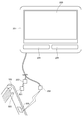
- FIG. 1 is an explanatory view showing the entire bicycle 1 according to the first embodiment of the present invention.
- the bicycle 1 includes a frame 3, a front wheel 5, a rear wheel 7, a handle 9, a saddle 11, a front fork 13, and a drive mechanism 101.
- the frame 3 is composed of two truss structures.
- a front fork 13 is rotatably connected to the front fork 13 in the forward direction.
- the front fork 13 is connected to the handle 9.
- the front fork 13 and the front wheel 5 are rotatably connected at the front end position of the front fork 13 in the downward direction.
- the front wheel 5 has a hub part, a spoke part, and a tire part.
- the hub portion is rotatably connected to the front fork 13. And this hub part and the tire part are connected by the spoke part.
- the frame 3 is rotatably connected to the rear wheel 7 at the rear end portion.
- the rear wheel 7 has a hub part, a spoke part, and a tire part.
- the hub portion is rotatably connected to the frame 3. And this hub part and the tire part are connected by the spoke part.
- the hub portion of the rear wheel 7 is connected to the rear gear 113.
- the bicycle 1 has a drive mechanism 101 that converts a stepping force by a user's foot into a driving force of the bicycle 1.
- the drive mechanism 101 includes a pedal 103, a crank mechanism 104, a front gear 109, a chain 111, and a rear gear 113.
- the pedal 103 is a part in contact with a foot for the user to step on.
- the crank mechanism 104 includes a crank 105, a crankshaft 107, and a pedal crankshaft 115 (not shown).
- the crankshaft 107 penetrates the frame 3 in the left-right direction.
- the crank 105 is formed at a right angle to the crankshaft 107.
- the crankshaft 107 is connected to the crank 105 at the end of the crank 105.
- the pedal crankshaft 115 is formed at a right angle to the crank 105.
- the axial direction of the pedal crankshaft 115 is the same as that of the crankshaft 107.
- the pedal crankshaft 115 is connected to the crank 105 at the end of the crank 105 opposite to the end where the crankshaft 107 is formed.
- the pedal crankshaft 115 and the pedal 103 are connected so that the pedal 103 can rotate freely.
- the crankshaft 107 is rotatably supported by the frame 3.
- the crank mechanism 104 has such a structure on the side opposite to the side surface of the bicycle 1. That is, the crank mechanism 104 has two cranks 105 and two pedal crankshafts 115, and has two pedals 103. When distinguishing whether these are on the right side or the left side of the bicycle 1, they are described as a right crank 105a, a left crank 105b, a right pedal crankshaft 115a, a left pedal crankshaft 115b, a right pedal 103a, and a left pedal 103b, respectively. To do.
- the right crank 105a and the left crank 105b are formed to extend in opposite directions around the crankshaft 107.
- the right pedal crankshaft 115a, the crankshaft 107, and the left pedal crankshaft 115b are formed on the same plane.
- the right pedal crankshaft 115a, the crankshaft 107, and the left pedal crankshaft 115b are formed in parallel.
- the right crank 105a and the left crank 105b are formed on the same plane.
- the axes of the right crank 105a and the left crank 105b are formed in parallel.
- the plane on which the right pedal crankshaft 115a, the crankshaft 107, and the left pedal crankshaft 115b are formed is the same as the plane on which the right crank 105a and the left crank 105b are formed.
- a front gear 109 is connected to the crankshaft 107.
- the front gear 109 is preferably formed of a variable gear that can change the gear ratio.
- a chain 111 is engaged with the front gear 109.
- the chain 111 is engaged with the rear gear 113.
- the rear gear 113 is preferably formed by a variable gear.
- the rear gear 113 is connected to the rear wheel 7.
- the bicycle 1 converts the stepping force of the user into the rotational force of the rear wheel 7.
- a measuring module 301 is disposed on the crank 105. Also, in the frame 3, a cycle computer cadence radio reception unit 207 and a cycle computer radio reception unit 209 are arranged. Further, a cycle computer 201 is disposed on the handle 9.
- FIG. 2 is an explanatory diagram of the positional relationship of the cycle computer 201, the measurement module 301, and the cadence sensor 501.
- the cycle computer 201 includes a cycle computer display unit 203 that displays various types of information and a cycle computer operation unit 205 that receives user operations.
- the various information includes the speed of the bicycle 1, position information, the distance to the destination, the expected arrival time to the destination, the travel distance since the departure, the elapsed time since the departure, the (average) power P, ( Average) loss amount.
- the average power P is the amount of energy per time due to the force applied in the rotation direction of the crank 105.
- the bicycle 1 is driven by the average power P.
- the loss amount is a force applied in a direction different from the rotation direction of the crank 105.
- the force applied in a direction different from the rotational direction is a useless force that does not contribute to the driving of the bicycle 1. Therefore, the user can drive the bicycle 1 more efficiently by increasing the average power P as much as possible and reducing the loss amount as much as possible.
- the cycle computer display unit 203 outputs the average power P in the rotational direction output by the user at each angle (every 30 °) of the crank 105, and the user outputs The average loss amount due to the force in the normal direction of human power is displayed.
- the cycle computer 201 includes a cycle computer cadence wireless reception unit 207 and a cycle computer wireless reception unit 209.
- the cycle computer cadence wireless reception unit 207 and the cycle computer wireless reception unit 209 are connected to the main body portion of the cycle computer 201 through wiring.
- the cycle computer cadence wireless reception unit 207 and the cycle computer wireless reception unit 209 need not have a reception-only function. For example, you may have a function as a transmission part.
- an apparatus described as a transmission unit or a reception unit may have both a reception function and a transmission function.
- the cadence sensor 501 has a reed switch 505 (see the portion on the cadence sensor 501 side in FIG. 3).
- the reed switch 505 detects the position of the magnet 503 because the reed switch 505 is turned on by the approaching magnet 503. That is, when the reed switch 505 is turned on, it is detected that the crank 105 is also present at the position where the reed switch 505 is present. From this cadence sensor 501, the cycle computer 201 can obtain cadence [rpm].
- a cadence sensor 501 may be used to calculate the position of the crank 105. From the position (angle) information of the crank 105, the rotation angle of the crank 105 is estimated. That is, the time interval at which the reed switch 505 is turned on coincides with the time interval at which the crank 105 rotates 360 °. Therefore, the current position of the crank 105 can be estimated from the elapsed time from the moment when the latest reed switch 505 is turned on. Specifically, (elapsed time) / (interval at which the reed switch 505 is turned on) ⁇ 360 ° is the rotation angle of the crank 105 when the position of the reed switch 505 is set as the initial rotation angle.
- 360 ° may be divided into 12 and the value may be obtained within that range.
- 360 ° is divided into 12 parts because what is desired to be presented to the user is the average power P that is the rotational force in a certain range of rotational sections.
- the cycle computer 201 calculates the average power P for each crank rotation angle (period divided every 30 °) based on the position information of the crank 105 from the cadence sensor 501.
- the cadence sensor 501 includes a cadence sensor wireless transmission unit 507 (see the portion on the cadence sensor 501 side in FIG. 3).
- the cadence sensor wireless transmission unit 507 transmits cadence information to the cycle computer cadence wireless reception unit 207.
- the position information of the crank 105 is detected and estimated by the magnet 503 and the reed switch 505.
- the position of the crank 105 is detected by an angle sensor (for example, a rotary encoder). Is also possible.
- the measurement module 301 detects the human force applied by the user to the pedal 103 using a plurality of strain sensors 366 provided on the crank 105 (see also FIGS. 3 and 1). Specifically, the measurement module 301 calculates an average torque that is the rotational force of the crank 105.
- FIG. 3 is a block diagram of the cycle computer 201, the measurement module 301, and the cadence sensor 501.
- the cadence sensor 501 includes a reed switch 505, a cadence sensor wireless transmission unit 507, a cadence sensor control unit 551, a cadence sensor storage unit 553, and a cadence sensor timer 561.
- the reed switch 505 detects ON / OFF of the reed switch 505 when the magnet 503 approaches. When the reed switch 505 is turned on, the reed switch 505 outputs an information signal to that effect to the cadence sensor control unit 551.
- the cadence sensor timer 561 is a timer counter and always counts a clock having a predetermined cycle.
- the cadence sensor timer 561 receives a value output command from the cadence sensor control unit 551
- the cadence sensor timer 561 outputs timer value information to the cadence sensor control unit 551.
- the cadence sensor timer 561 receives a reset command from the cadence sensor control unit 551
- the cadence sensor timer 561 resets the value of the timer counter to an initial value.
- the cadence sensor timer 561 also has a role of instructing the cadence sensor wireless transmission unit 507 to transmit timing. Specifically, for example, the transmission timing is commanded to the cadence sensor wireless transmission unit 507 every second.
- the cadence sensor wireless transmission unit 507 transmits the cadence information stored in the cadence sensor storage unit 553 to the cycle computer cadence wireless reception unit 207.
- the transmission by the cadence sensor wireless transmission unit 507 is performed every second when instructed by the cadence sensor timer 561.
- a determination based on the value of the cadence sensor timer 561 is performed by the cadence sensor control unit 551, and based on the determination, transmission by the cadence sensor wireless transmission unit 507 is performed according to a command from the cadence sensor control unit 551. good.
- the cadence sensor storage unit 553 includes a cadence sensor RAM 555 and a cadence sensor ROM 557.
- the cadence sensor RAM 555 stores timer values and the like, and the cadence sensor ROM 557 stores control programs and the like.
- the cadence sensor control unit 551 comprehensively controls the cadence sensor 501. Specifically, when the cadence sensor control unit 551 receives an output of an information signal indicating that the reed switch 505 is turned on, the cadence sensor control unit 551 performs the following operation. The cadence sensor control unit 551 instructs the cadence sensor timer 561 to output timer value information. When the cadence sensor control unit 551 receives timer value information from the cadence sensor timer 561, the cadence sensor control unit 551 calculates cadence from the timer value information.
- the time (period) [s] for which the reed switch 505 is turned on is calculated by multiplying the count value (C) of the timer value information by one count interval (T). Then, cadence [rpm] is calculated by dividing 60 by this period. Further, the cadence sensor control unit 551 stores the cadence information in the cadence sensor RAM 555 of the cadence sensor storage unit 553. The cadence sensor control unit 551 outputs a counter value reset command to the cadence sensor timer 561. The cadence sensor control unit 551 may cause the cadence sensor wireless transmission unit 507 to transmit the cadence information stored in the cadence sensor storage unit 553 at intervals of 1 second.
- the measurement module 301 includes a measurement module wireless transmission unit 309, a measurement module timer 361, a measurement module control unit 351, a measurement module storage unit 353, a measurement module A / D 363, and a measurement module distortion detection circuit 365. And a strain sensor 366.
- the strain sensor 366 is bonded to the crank 105 and integrated.
- the upper and lower surface strain gauge set 369 includes an upper and lower surface first strain gauge 369a and an upper and lower surface second strain gauge 369b.
- the upper and lower surface first strain gauges 369a and the upper and lower surface second strain gauges 369b are orthogonal to each other. That is, the strain detection direction of the upper and lower surface first strain gauges 369a and the strain detection direction of the upper and lower surface second strain gauges 369b are orthogonal to each other (see also FIGS. 4, 8, and 13).
- the terminals of the upper and lower surface first strain gauges 369a and the upper and lower surface second strain gauges 369b are connected to the measurement module strain detection circuit 365 (see FIG. 4 for the specific configuration of the measurement module strain detection circuit 365). See The measurement module strain detection circuit 365 amplifies and adjusts the output of the upper and lower surface first strain gauges 369a and the output of the upper and lower surface second strain gauges 369b.
- the output of the upper and lower surface first strain gauges 369a and the output of the upper and lower surface second strain gauges 369b amplified by the measurement module strain detection circuit 365 are converted from analog information to strain information which is digital information by the measurement module A / D 363. Is done.
- the distortion information signal is output to the measurement module storage unit 353.
- the distortion information signal input to the measurement module storage unit 353 is stored in the measurement module RAM 355 as distortion information.
- the measurement module timer 361 is a timer counter and always counts a clock having a predetermined period. Furthermore, the measurement module timer 361 also has a role of instructing the measurement module wireless transmission unit 309 to transmit timing. Specifically, for example, the transmission timing is commanded to the measurement module wireless transmission unit 309 every second.
- the measurement module wireless transmission unit 309 transmits the average torque information calculated from the strain information by the measurement module control unit 351 to the cycle computer wireless reception unit 209. Transmission of the average torque by the measurement module wireless transmission unit 309 is performed every second as instructed by the measurement module timer 361. Alternatively, the measurement module wireless transmission unit 309 may transmit the average torque information when the measurement module control unit 351 outputs a command based on the value of the measurement module timer 361.
- the various types of information are, for example, a control program for the measurement module control unit 351 and temporary information required when the measurement module control unit 351 performs control.
- distortion information is stored.
- the measurement module storage unit 353 includes a measurement module RAM 355 and a measurement module ROM 357.
- the measurement module RAM 355 stores distortion information and the like.
- the measurement module ROM 357 stores a control program and various parameters, constants, and the like for calculating the average torque from the strain information.
- the measurement module storage unit 353 also stores various parameters and the like required by the equations (3) to (13).
- the measurement module control unit 351 comprehensively controls the measurement module 301. Specifically, the measurement module control unit 351 calculates an average torque from the strain information.
- X is the measured distortion amount
- the distortion amount when the crank 105 is horizontal and m [kg] is placed vertically on the pedal 103 is Xc
- the distortion amount in each unloaded state is Xz.
- the distance from the crankshaft 107 to the pedal 103 is L.
- g is a gravitational acceleration. That is, the torque can be calculated by substituting the strain information into X in this equation.
- This torque is calculated for each of a plurality of points in time, and the average is obtained as the average torque. Then, the calculated average torque is transmitted to the cycle computer 201 via the measurement module wireless transmission unit 309 every other second. Further, in the case of the advanced embodiment in which one rotation is divided into 12 and displayed on the cycle computer display unit 203, the torque at each time point within the range of 30 ° is calculated from the above formula and included in the range. An average torque is calculated by averaging a plurality of torques.
- the cycle computer 201 includes a cycle computer display unit 203, a cycle computer operation unit 205, a cycle computer cadence wireless reception unit 207, a cycle computer wireless reception unit 209, a cycle computer timer 261, and a cycle computer storage unit. 253 and a cycle computer control unit 251.
- the cycle computer operation unit 205 receives a user instruction (input). For example, the cycle computer operation unit 205 receives a display content instruction from the user on the cycle computer display unit 203.
- the cycle computer display unit 203 displays various types of information based on user instructions and the like.
- the average power P is visualized and displayed.
- the average torque (every 30 °) of the crank 105 is visualized and displayed.
- Any visualization method may be used.
- the visualization method here may be, for example, vector display, graph display, color-coded display, symbol display, three-dimensional display, etc., and any method may be used. Also, a combination thereof may be used.
- the cycle computer cadence wireless reception unit 207 receives cadence information transmitted from the cadence sensor 501.
- the cycle computer wireless reception unit 209 receives the average torque information transmitted from the measurement module 301.
- the cycle computer timer 261 is a timer counter and counts the timer.
- the timer value information generated by the cycle computer timer 261 is used in various ways by the cycle computer control unit 251 and the like.
- the cycle computer storage unit 253 includes a cycle computer RAM 255 and a cycle computer ROM 257.
- the cycle computer ROM 257 stores a control program and various parameters, constants, and the like for calculating the average power P from the average torque information.
- the cycle computer control unit 251 comprehensively controls the cycle computer 201. Further, the cadence sensor 501 and the measurement module 301 may be comprehensively controlled. Further, the cycle computer control unit 251 calculates the average power P. Specifically, the cycle computer control unit 251 calculates the average power P for a certain period from the average torque information and the cadence information.
- Tra is the average torque [Nm]
- R is the cadence amount [rpm].
- PI is the circumference ratio. That is, the average power P can be calculated by substituting the average torque information and the cadence information into the average torques Tra and R of this equation. Further, when the rotation is divided into 12 parts and displayed on the cycle computer display unit 203 as in the advanced embodiment, the average power P within a range of 30 ° is calculated.
- FIG. 4 is an explanatory diagram of the upper and lower strain gauge set 369 and the measurement module strain detection circuit 365.
- the upper and lower surface first strain gauges 369a and the upper and lower surface second strain gauges 369b are arranged orthogonally and stacked.
- the resistance value of the upper and lower first strain gauges 369a is about R0 when the upper and lower first strain gauges 369a are not compressed or expanded.
- the resistance value of the upper and lower second strain gauges 369b is approximately R0 when the upper and lower second strain gauges 369b are not compressed or expanded.
- the upper and lower surface first strain gauges 369a and the upper and lower surface second strain gauges 369b decrease in resistance when compressed, and increase in resistance when expanded. This change in resistance value is proportional when the amount of change is small.
- the resistance value when ⁇ l is expanded and contracted is R0 + ⁇ R0.
- the resistance value when ⁇ l compression is performed is R0 ⁇ R0.
- the detection direction of the upper and lower first strain gauges 369a is the direction in which the wiring extends, and in FIG.
- the detection direction of the upper and lower second strain gauges 369b is the direction in which the wiring extends, and in FIG. That is, when compression or expansion occurs in this detection direction, resistance values change in the upper and lower surface first strain gauges 369a and the upper and lower surface second strain gauges 369b.
- the resistance value does not change in the upper and lower surface first strain gauges 369a and the upper and lower surface second strain gauges 369b.
- the measurement module distortion detection circuit 365 includes an upper and lower surface bridge circuit 373A, an upper and lower surface amplification circuit 375A, and an upper and lower surface reference voltage circuit 377A.
- the upper and lower surface first strain gauges 369a and the upper and lower surface second strain gauges 369b are arranged at diagonal positions of the upper and lower surface bridge circuit 373A. Specifically, on the first system side, the upper and lower surface first strain gauges 369a, the upper and lower surface first connection points 373A-1, and the resistor R are connected in this order from the power source Vcc. On the second system side, the resistor R, the upper and lower surface second connection points 373A-2, and the upper and lower surface second strain gauges 369b are connected in this order from the power source Vcc.
- the resistance R of the first system and the resistance R of the second system have the same resistance value. Further, the resistance R of the first system and the resistance R of the second system are the same resistance as R0 which is the resistance value before the compression or expansion of the upper and lower surface first strain gauges 369a and the upper and lower surface second strain gauges 369b occurs. Has a value. As a result, the potential difference generated between the upper and lower surface first connection point 373A-1 and the upper and lower surface second connection point 373A-2 is substantially zero.
- the upper and lower surface first strain gauges When an expansion change occurs in an intermediate direction between the detection direction of the upper and lower surface first strain gauges 369a and the detection direction of the upper and lower surface second strain gauges 369b (left and right direction in FIG. 4A), the upper and lower surface first strain gauges.
- the gauge 369a and the upper and lower second strain gauges 369b extend.
- the resistance values of the upper and lower surface first strain gauges 369a and the upper and lower surface second strain gauges 369b are similarly R0 + ⁇ R0, for example.
- the potential at the upper and lower surface first connection point 373A-1 of the first system is reduced, while the potential at the upper and lower surface second connection point 373A-2 of the second system is increased.
- an output is detected from the measurement module distortion detection circuit 365. The same applies when both the upper and lower surface first strain gauges 369a and the upper and lower surface second strain gauges 369b are compressed by the same amount.
- the resistance value of the upper and lower surface first strain gauges 369a is R0 ⁇ R0 and The resistance value of the two strain gauges 369b is R0 + ⁇ R0.
- the potential of the first connection point 373A-1 at the upper and lower surfaces of the first system increases, but the voltage drop of the second system also increases.
- ⁇ R0 is sufficiently smaller than R and R0.
- no output is detected from the measurement module distortion detection circuit 365.
- the configuration of the upper / lower surface amplification circuit 375A and the upper / lower surface reference voltage circuit 377A has a configuration as shown in FIG.
- the upper / lower surface amplification circuit 375A is a circuit that amplifies a potential difference between the upper and lower surface first connection point 373A-1 and the upper and lower surface second connection point 373A-2.
- the upper and lower reference voltage circuit 377A is a circuit for increasing / decreasing the output from the upper / lower amplifier circuit 375A around 1 ⁇ 2 of the power supply Vcc. The reason why the upper / lower reference voltage circuit 377A is necessary will be described.
- the voltage output from the upper / lower amplifier circuit 375A is converted from an analog value to a digital value by the measurement module A / D363.
- an analog / digital converter that can measure only plus and minus can simplify the circuit configuration and can be constructed at a lower cost than one that can measure both plus and minus.
- the potential difference between the upper and lower surface first connection point 373A-1 and the upper and lower surface second connection point 373A-2 can change to both the plus side and the minus side. Therefore, an upper / lower surface reference voltage circuit 377A is provided to change the potential difference between the upper / lower surface first connection point 373A-1 and the upper / lower surface second connection point 373A-2 to a change only on the plus side.
- FIG. 5 is an explanatory diagram of the force applied to the right crank 105a.
- the crank mechanism 104 includes a left pedal 103b, a left crank 105b, a crankshaft 107, a right crank 105a, a right pedal crankshaft 115a, and a right pedal 103a.
- human power FL applied by the user is applied to the right pedal 103a.
- the human force FL is composed of a rotational force F ⁇ of the crank 105 and a normal force Fr of the crank 105.
- a direction perpendicular to the rotation direction and the normal direction is defined as an inward / outward direction.
- the distortion of the crank 105 that occurs in the rotation direction of the crank 105 is referred to as rotation direction distortion.
- the distortion of the crank 105 that occurs in the inward / outward direction is referred to as inward / outward distortion.
- distortion caused by the torsional force generated in the crank 105 is referred to as torsional direction distortion.
- a central portion on the upper surface side (or lower surface side) of the right crank 105 a is defined as an upper and lower surface portion 117.
- a central portion of the side surface of the right crank 105a is referred to as a side surface portion 119.
- forces applied to the upper and lower surface portions 117 and the side surface portions 119 will be described.
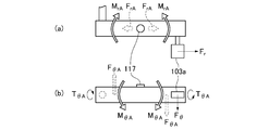
- FIG. 6 is an explanatory diagram of forces applied to the upper and lower surface portions 117.
- FIG. 6A is an explanatory diagram of the force applied to the upper and lower surface portions 117 by the force Fr in the normal direction.
- FIG. 6B is an explanatory diagram of the force applied to the upper and lower surface portions 117 by the force F ⁇ in the rotation direction.
- the tensile force FrA and the moment MrA are generated in the upper and lower surface portions 117 by the force Fr in the normal direction.
- the strain amount due to the tensile tension FrA is considerably smaller than the strain amount due to the moment MrA, it is sufficient to consider only the moment MrA.
- shear force F ⁇ A, moment M ⁇ A, and torque T ⁇ A are generated in the upper and lower surface portions 117 by the force F ⁇ in the rotation direction.
- the amount of strain caused by the shear force F ⁇ A is considerably smaller than the amount of strain caused by the moment M ⁇ A and the amount of strain caused by the torque T ⁇ A, it is sufficient to consider only the moment M ⁇ A and the torque T ⁇ A.
- the strain detected by the strain sensor 366 is caused by the internal / external strain caused by the moment MrA due to the normal force Fr and the rotational force F ⁇ .
- the moment M ⁇ A due to the normal force Fr
- the rotational force F ⁇ There are only a rotational direction distortion caused by the moment M ⁇ A in the rotational direction and a torsional direction distortion caused by the torque T ⁇ A.
- FIG. 7 is an explanatory diagram of the force applied to the side surface portion 119.
- FIG. 7A is an explanatory diagram of the force applied to the side surface portion 119 by the normal direction force Fr.
- FIG. 7B is an explanatory diagram of the force applied to the side surface portion 119 by the rotational force F ⁇ .
- the tensile force FrB and the moment MrB are generated in the side surface portion 119 by the force Fr in the normal direction.
- the strain amount due to the tensile tension FrB is considerably smaller than the strain amount due to the moment MrB, it is sufficient to consider only the moment MrB.
- FIG. 7A is an explanatory diagram of the force applied to the side surface portion 119 by the normal direction force Fr.
- FIG. 7B is an explanatory diagram of the force applied to the side surface portion 119 by the rotational force F ⁇ .
- the tensile force FrB and the moment MrB are generated in the side surface portion 119 by the force Fr in the normal direction.
- a shearing force F ⁇ B, a moment M ⁇ A, and a torque T ⁇ B are generated in the side surface portion 119 by the force F ⁇ in the rotation direction.
- the amount of strain caused by the shear force F ⁇ B is considerably smaller than the amount of strain caused by the moment M ⁇ B and the amount of strain caused by the torque T ⁇ B, it is sufficient to consider only the moment M ⁇ B and the torque T ⁇ B.
- the strain detected by the strain sensor 366 is the internal / external strain generated in the internal / external direction by the moment MrB due to the normal force Fr, and the moment due to the rotational force F ⁇ . Only the rotational direction distortion caused by M ⁇ B in the rotational direction and the torsional direction distortion caused by torque T ⁇ B.
- FIG. 8 is an explanatory diagram of the arrangement of the upper and lower surface strain gauge sets 369 provided on the crank 105, and an explanatory diagram of the reason why the force applied to the upper and lower surface strain gauge sets 369 is cancelled.
- the upper and lower surface strain gauge sets 369 are arranged on the upper and lower surface portions 117.
- the upper and lower surface portions 117 are arranged at the center portion of the upper surface or the lower surface of the crank 105.
- the upper and lower surface strain gauge sets 369 are disposed at the center portion of the strain due to the moment MrA. More specifically, as shown in FIG.
- the strain is arranged so that the center of strain due to the moment MrA comes to the center of the upper and lower strain gauge sets 369.
- the upper / lower surface strain gauge set 369 may be located on the right side of the position shown in FIG. 8A or on the left side of FIG. 8A. In other words, if the center of strain due to the moment MrA comes to the center of the upper and lower surface strain gauge set 369, the upper and lower surface strain gauge set 369 may be on the right pedal 103a side or the crankshaft 107 side.
- the upper and lower surface strain gauge set 369 includes an upper and lower surface first strain gauge 369a and an upper and lower surface second strain gauge 369b.
- the upper and lower surface first strain gauges 369a and the upper and lower surface second strain gauges 369b are arranged orthogonally and in layers. Further, the intermediate direction between the detection direction of the upper and lower surface first strain gauges 369 a and the detection direction of the upper and lower surface second strain gauges 369 b is arranged to be the longitudinal direction of the crank 105. That is, the detection direction of the upper and lower first strain gauges 369a and the direction of the axis of the crank 105 have an angle of 45 degrees. The detection direction of the upper and lower second strain gauges 369b and the direction of the axis of the crank 105 have an angle of 45 degrees (see also FIG. 4A for the detection direction). In FIG.
- the upper and lower surface strain gauge set 369 is provided on the upper surface side of the crank 105, but the upper and lower surface strain gauge set 369 may be provided on the lower surface side of the crank 105. Further, the upper and lower strain gauge sets 369 may be provided inside the crank 105. Specifically, the upper and lower strain gauge sets 369 may be bonded to the hollow inner surface with the crank 105 hollow. Further, the upper and lower strain gauge sets 369 may be embedded in the crank 105.
- the upper and lower strain gauge sets 369 (upper and lower surface portions 117) are acted by the moment MrA due to the normal direction force Fr, the moment M ⁇ A due to the rotational force F ⁇ , and the torque T ⁇ A (FIG. 8A). (See also 6).
- the output from the measurement module distortion detection circuit 365 does not change (see also the explanation part of FIG. 4A). Therefore, the moment MrA due to the force Fr in the internal / external force direction can be canceled. The same applies to the upper and lower second strain gauges 369b.
- the torque T ⁇ A caused by the rotational force F ⁇ is canceled.
- the upper and lower strain gauge sets 369 are distorted as shown in FIG. 8C (note that FIG. 8C is highlighted and simplified).
- the upper and lower surface first strain gauges 369a are expanded, and the upper and lower surface second strain gauges 369b are compressed.
- the resistance value of the upper and lower surface first strain gauges 369a is R0 + ⁇ R0, and the upper and lower surface second strain gauges 369a.
- the resistance value of the gauge 369b is R0 ⁇ R0.
- the upper and lower surface first strain gauges 369a change to the positive side
- the upper and lower surface second strain gauges 369b change to the negative side
- the upper and lower surface first strain gauges 369a change to opposite values.
- the gauge 369a changes to the negative side
- the upper and lower second strain gauges 369b change to the positive side. That is, even if the upper and lower surface strain gauge sets 369 are inclined and arranged, the torque T ⁇ A due to the force F ⁇ in the rotation direction can be canceled.
- the output of the measurement module strain detection circuit 365 that has processed the output from the upper and lower strain gauge sets 369 is only due to the strain due to the moment M ⁇ A due to the force F ⁇ in the rotational direction. Therefore, if the strain generated in the upper and lower strain gauge set 369 is detected, the rotational force F ⁇ and the torque caused by the rotational force F ⁇ can be detected. Specifically, the torque can be calculated by substituting strain information output from the upper / lower surface strain gauge set 369 via the upper / lower surface bridge circuit 373A into the equation (1). Note that the term “torque” refers to torque generated in the rotational direction.
- the cycle computer 201 performs various processes on the calculated torque and displays it on the cycle computer display unit 203. Specifically, the average power P is calculated and displayed on the cycle computer display unit 203.
- FIG. 9 is a flowchart of processing of the cadence sensor 501.
- FIG. 10 is a flowchart of processing of the measurement module 301 and the cycle computer 201. 10A and 10B illustrate the processing of the measurement module 301, and FIG. 10C illustrates the processing of the cycle computer 201.
- step ST51 the cadence sensor control unit 551 of the cadence sensor 501 detects a magnetic change of the reed switch 505. Then, when the cadence sensor control unit 551 detects the reed switch 505, the cadence sensor control unit 551 starts processing of the following step ST02 and step ST03. That is, the cadence sensor control unit 551 interrupts the process when detecting an output from the reed switch 505, and starts the processes after step ST02.
- the term “interrupt” refers to executing a specified process by interrupting the process so far.
- the cadence sensor control unit 551 calculates a cadence value.
- the cadence sensor control unit 551 calculates the time (period) [s] for which the reed switch 505 is turned on by multiplying the count number (C) of the timer value information by one count interval (T). Then, the cadence sensor control unit 551 calculates cadence [rpm] by dividing 60 by this time (cycle). Further, the cadence sensor control unit 551 stores the cadence information in the cadence sensor RAM 555 of the cadence sensor storage unit 553.
- step ST55 the cadence sensor control unit 551 outputs a counter value reset command to the cadence sensor timer 561.
- the main flow of control of the cadence sensor control unit 551 is completed.
- the interruption is performed again, and the process is restarted from step ST51.
- step ST ⁇ b> 57 the cadence sensor control unit 551 transmits the cadence information stored in the cadence sensor storage unit 553 to the cycle computer 201 using the cadence sensor wireless transmission unit 507.
- the transmission may be performed only by the cadence sensor wireless transmission unit 507 without using the cadence sensor control unit 551.
- step ST59 the cadence sensor control unit 551 performs one second.
- the wait time is variable.
- step ST11 the measurement module A / D 363 A / D converts the output from the measurement module distortion detection circuit 365 from an analog value to a digital value. That is, the amount of distortion caused by the moment M ⁇ A is detected as a digital value. The moment M ⁇ A is generated by the force F ⁇ in the rotation direction of the human power output by the user.
- step ST13 the distortion information detected (converted) by the measurement module A / D 363 is stored in the measurement module RAM 355 of the measurement module storage unit 353.
- step ST15 the process waits for 1 / N [s] seconds.
- the value of N is the number of data points measured per second. In other words, the larger the value of N, the greater the number of distortion data and the higher the resolution in seconds. If possible, the larger the N value, the better. However, if the N value is too large, the measurement module RAM 355 must have a large capacity, resulting in an increase in cost. Therefore, the N value can be determined by the cost, the required time resolution, the time required for the measurement module A / D 363 to perform A / D conversion, and the like.
- the process of step ST15 ends, the process returns to step ST11 again. That is, the processing of step ST11 to step ST15 is repeated N times per second.
- the measurement module control unit 351 performs the process of FIG. In step ST31, the measurement module control unit 351 saves the distortion information data.
- the capacity of the measurement module RAM 355 in the measurement module storage unit 353 is limited.
- the capacity of the measurement module RAM 355 is increased, it is not necessary to save the distortion information data.
- the design is made with a sufficient margin, the cost increases, which is not appropriate.
- new information may be overwritten before torque Tr is calculated by processing in step ST33 described later. .
- the measurement module control unit 351 calculates an average torque. Specifically, the measurement module control unit 351 calculates the torque Tr by inputting strain information to the equation (1) described with reference to FIG. Further, the measurement module control unit 351 calculates N torques Tr and calculates an average thereof. That is, the measurement module control unit 351 calculates an average (average torque information) of the torque Tr for one second.
- step ST35 the measurement module control unit 351 transmits the calculated average torque information via the measurement module wireless transmission unit 309.
- the transmitted average torque information is received by the cycle computer radio reception unit 209 of the cycle computer 201.
- step ST37 1 [s] waits. One second is an example and can be changed as necessary.
- the process of step ST37 ends the process returns to step ST31 again. That is, the processing of step ST31 to step ST35 is repeated once per second.
- step ST71 when the cycle computer control unit 251 receives the average torque information and the cadence information, an interruption is performed. That is, when the cycle computer control unit 251 detects that the cycle computer wireless reception unit 209 has received the average torque information and cadence information, the cycle computer control unit 251 interrupts (interrupts) the process, and performs the processes in and after step ST73. To start.
- Tra is the average torque [Nm]
- R is the cadence strain amount [rpm]. That is, the average power P can be calculated by substituting the average torque information and the cadence information into Tra and R in this equation.
- step ST75 the cycle computer control unit 251 causes the cycle computer display unit 203 to display the average power P.
- the cycle computer display unit 203 displays the average power P as a numerical value, or transmits information on the average power P to the user by other visualization, hearing, or tactile methods.
- step ST77 the cycle computer control unit 251 stores the calculated average power P information in the cycle computer RAM 255 of the cycle computer storage unit 253. Thereafter, the cycle computer control unit 251 performs other processes until the interrupt of step ST51 is performed again.
- the upper and lower surface first strain gauges 369a and the upper and lower surface second strain gauges 369b are arranged orthogonally and at the diagonal positions of the upper and lower surface bridge circuits 373A, thereby mounting angles. Even if there is an error, it is possible to eliminate the influence of distortion in the torsional direction. That is, with such a configuration, it is possible to detect only the distortion in the rotation direction due to the force F ⁇ in the rotation direction. The reason is explained in FIG. 8 (c).
- the accurate position means a position where the center of strain due to the moment MrA is located at the center of the upper and lower strain gauge set 369 as shown in FIG.
- the accurate direction is a direction in which an intermediate direction between the detection direction of the upper and lower surface first strain gauges 369 a and the detection direction of the upper and lower surface second strain gauges 369 b is the longitudinal direction of the crank 105. That is, only the distortion in the rotation direction can be detected, and the force F ⁇ in the rotation direction can be calculated. The reason is explained with reference to FIG. That is, both expansion and compression occur in the upper and lower surface first strain gauges 369a, and the resistance value of the upper and lower surface first strain gauges 369a does not change. That is, the output from the measurement module distortion detection circuit 365 does not change.
- the measurement module 301 including the upper and lower surface strain gauge sets 369 can be attached after the bicycle is manufactured. That is, by attaching the upper and lower strain gauge sets 369 to appropriate positions and arranging the measurement module 301, the user or the like can provide a function for measuring the average power P as a retrofit.
- the upper and lower surface strain gauge set 369 is arranged at a position where the center of strain due to the moment MrA comes to the center of the upper and lower surface strain gauge set 369.
- This positional shift means that the upper and lower surface strain gauge sets 369 detect the moment MrA, and it is impossible to detect only the strain due to the moment M ⁇ A caused by the force F ⁇ in the rotation direction.
- the upper and lower strain gauge set 369 can detect only the average torque due to the rotational force F ⁇ , and cannot calculate the average loss amount due to the normal direction force Fr.
- the average loss amount is the force that the user is outputting even though it does not become the driving force of the bicycle 1. And reducing this force as much as possible leads to driving the bicycle 1 efficiently. Therefore, it is important to provide this average loss amount to the user.
- FIG. 11 is a block diagram of the cycle computer 201, the measurement module 301, and the cadence sensor 501 in the second embodiment.
- the basic configuration is the same as in FIG. 3, and the description of the same parts is omitted.
- the side strain gauge set 371 includes a side first strain gauge 371a and a side second strain gauge 371b.
- FIG. 12 is an explanatory diagram of the measurement module strain detection circuit 365, the upper and lower surface strain gauge sets 369, and the side surface strain gauge set 371 in the second embodiment.
- the measurement module strain detection circuit 365 in addition to the upper and lower surface bridge circuit 373A and the upper and lower surface amplification circuit 375A for the upper and lower surface strain gauge set 369, the measurement module strain detection circuit 365 includes the side surface bridge circuit 373B and the side surface for the side surface strain gauge set 371.
- An amplifier circuit 375B is provided.
- the internal configuration of the side bridge circuit 373B is the same as that of the upper and lower side bridge circuit 373A.
- the internal configuration of the side surface amplifier circuit 375B is the same as that of the upper and lower surface amplifier circuit 375A.
- the side bridge circuit 373B has a side first connection point 373B-1 on the first system side and a side second connection point 373B-2 on the second system side, similarly to the upper and lower surface bridge circuit 373A. .
- FIG. 13 is an explanatory diagram of the arrangement of the side strain gauge set 371 provided on the crank 105 and the reason why the force applied to the side strain gauge set 371 is canceled in the second embodiment.
- the side surface strain gauge set 371 is disposed on the side surface portion 119.
- the side surface portion 119 is disposed at the central portion of the side surface of the crank 105 (on the crankshaft 107 side and the opposite side).
- the shape of the crank 105 is not a rectangular parallelepiped, it is appropriate that the side strain gauge set 371 is disposed at the center portion of the strain due to the moment M ⁇ B. More specifically, as shown in FIG.
- the strain center due to the moment M ⁇ B is arranged so as to be at the center of the side strain gauge set 371.
- the side strain gauge set 371 may be located on the right side of the position shown in FIG. 13A or on the left side of FIG. 13A. That is, as long as the center of strain due to the moment M ⁇ B comes to the center of the side strain gauge set 371, the side strain gauge set 371 may be on the right pedal 103a side or the crankshaft 107 side.
- the side surface strain gauge set 371 includes a side surface first strain gauge 371a and a side surface second strain gauge 371b.
- the side surface first strain gauge 371a and the side surface second strain gauge 371b are arranged orthogonally and in layers.
- the intermediate direction between the detection direction of the side surface first strain gauge 371 a and the detection direction of the side surface second strain gauge 371 b is arranged to be the longitudinal direction of the crank 105. That is, the detection direction of the side first strain gauge 371a and the axis direction of the crank 105 have an angle of 45 degrees. The detection direction of the side surface second strain gauge 371b and the axis direction of the crank 105 have an angle of 45 degrees (see also FIG. 4A for the detection direction).
- the side strain gauge set 371 is provided on the side opposite to the crankshaft 107 side of the crank 105, but the side strain gauge set 371 may be provided on the crankshaft 107 side (that is, the crankshaft).
- the side strain gauge set 371 may be provided on the opposite side). Further, the side strain gauge set 371 may be provided inside the crank 105. Specifically, the side strain gauge set 371 may be bonded to the hollow inner surface with the crank 105 hollow. Further, the side strain gauge set 371 may be embedded in the crank 105. As will be described later, in reality, it is difficult for the center of the strain due to the moment M ⁇ B to be the center of the side strain gauge set 371, and therefore correction is performed.
- the side surface strain gauge set 371 (side surface portion 119) is subjected to the moment MrB due to the normal direction force Fr, the moment M ⁇ B due to the rotational direction force F ⁇ , and the torque T ⁇ B (also in FIG. 7). See
- the side strain gauge set 371 If the strain due to the moment M ⁇ B is arranged so that the center of the strain is located at the center of the side strain gauge set 371, the side strain gauge set 371 generates strain as shown in FIG. 13B (note that FIG. 13B). Is highlighted and simplified.) Then, as shown in FIG. 13B, the lower part of the side surface first strain gauge 371a is expanded, and the upper part of the side surface first strain gauge 371a is compressed. As a result, both expansion and compression occur in the side surface first strain gauge 371a, and the resistance value of the side surface first strain gauge 371a does not change. That is, the output from the measurement module distortion detection circuit 365 (side amplification circuit 375B) does not change. Therefore, the moment M ⁇ B caused by the rotational force F ⁇ can be canceled. The same applies to the side surface second strain gauge 371b.
- the side strain gauge set 371 is distorted as shown in FIG. 13C (note that FIG. 13C is highlighted and simplified). Then, as shown in FIG. 13C, the side surface first strain gauge 371a is expanded, and the side surface second strain gauge 371b is compressed.
- the resistance value of the side face first strain gauge 371a is R0 + ⁇ R0 and the resistance of the side face second strain gauge 371b. The value is R0- ⁇ R0.
- the voltage drop at the side first connection point 373B-1 of the first system becomes large, while the voltage drop of the second system also becomes large.
- ⁇ R0 is sufficiently smaller than R0.
- the torque T ⁇ B due to the rotational force F ⁇ can be canceled.
- the mounting angle of the side strain gauge set 371 is slightly inclined, in the case of strain due to the torque T ⁇ B due to the rotational force F ⁇ as shown in FIG. 13C, the change in the side first strain gauge 371a and the second side strain gauge 371a.
- the change of the strain gauge 371b changes to a value opposite to each other, and the amount of change is the same.
- the side first strain gauge 371a changes to the positive side
- the side second strain gauge 371b changes to the negative side
- the side first strain gauge 371a changes to the opposite side.
- the side surface second strain gauge 371b changes to the positive side. That is, even if the attachment of the side strain gauge set 371 is inclined, the torque T ⁇ B due to the force F ⁇ in the rotation direction can be canceled.
- Y is the amount of distortion that is output, and the amount of distortion when the crank 105 is at bottom dead center and m [kg] is placed vertically on the pedal 103 is Yu, and the amount of distortion in each unloaded state. Is Yz.
- g is a gravitational acceleration.
- Y is strain information output from the side surface strain gauge set 371 via the side surface bridge circuit 373B. This makes it possible to calculate the amount of loss in the normal direction of the human power output by the user.
- the cycle computer 201 performs various processes on the calculated loss amount and displays it on the cycle computer display unit 203. Specifically, the average loss amount is calculated by averaging the loss amounts at a plurality of points and displayed on the cycle computer display unit 203.
- the specific processing is the same as that of the first embodiment except that the assigned expression is changed from the expression (1) to the expression (3) (see also FIG. 9 and FIG. 10). )
- the vertical strain gauge set 369 is affected by the moment MrA of the force Fr in the normal direction.
- the side strain gauge set 371 is affected by the moment M ⁇ A of the rotational force F ⁇ . Therefore, in the second embodiment, the influence is removed by the following method. As described above, the torque T ⁇ A and the torque T ⁇ B due to the force F ⁇ in the rotational direction can be canceled even if the mounting position is not accurate or the mounting direction is not accurate.
- the displacement of the mounting position (deviation from the strain center of the moment MrA) occurring in the upper and lower strain gauge set 369 has the following influence on the upper and lower strain gauge set 369.
- Strain value of upper and lower surface strain gauge set 369 X r + kn (Hereinafter, this equation is referred to as equation (4).)
- the displacement of the attachment position (deviation from the strain center of the moment M ⁇ B) also affects the side surface strain gauge set 371 as follows.
- the torque Tr can be obtained as follows by correcting the equation (1).
- Torque Tr [Nm] mgL (Xh ⁇ Xz) / (Xc ⁇ Xz) is calculated (hereinafter, this equation is referred to as equation (7)).
- this equation is referred to as equation (7).
- the crank 105 is in a horizontal state and m [kg] is placed vertically on the pedal 103, the distortion amount is Xc, and the distortion amount in each unloaded state is Xz.
- the distance to the pedal 103 is L.
- g is a gravitational acceleration.
- the corrected rotation output Xh can be obtained as follows.
- A is 1 / (1-kl) and is a proportionality constant.
- the loss amount can be obtained as follows by correcting the equation (3).
- Loss amount mg (Yh ⁇ Yz) / (Yu ⁇ Yz) (hereinafter, this equation is referred to as equation (11)).
- the amount of distortion when the crank 105 places m [kg] vertically on the pedal 103 at the bottom dead center is Yu, and the amount of distortion in each unloaded state is Yz. g is a gravitational acceleration.
- the correction loss output Yh can be obtained as follows.
- Correction loss output Yh Yq (X ⁇ Xz) (Hereinafter, this equation is referred to as equation (12).)
- q value can be calculated
- (Yu ⁇ Yz) q (Xu ⁇ Xz) (Hereinafter, this equation is referred to as equation (13).)
- X is Xu when the crank 105 is at bottom dead center.
- the q value is calculated by substituting the value into the equation (13).
- the corrected loss output Yh is calculated by substituting the strain value X from the upper and lower surface strain gauge sets 369 and the strain value Y from the side surface strain gauge set 371 into the equation (12). Note that. Xz here has already been measured. Furthermore, the amount of loss can be calculated by substituting Yh into equation (11). Xz has also been measured.
- the side surface first strain gauge 371a and the side surface second strain gauge 371b are arranged orthogonal to each other and arranged at the diagonal position of the side surface bridge circuit 373B. Even if there is an error in the angle, it is possible to remove the influence of distortion in the torsional direction. That is, with such a configuration, it is possible to detect only the distortion caused by the rotational force F ⁇ . The reason is explained in FIG. 8 (c). That is, even if the mounting angle of the upper and lower strain gauge sets 369 is slightly inclined, the change in the side first strain gauge 371a and the change in the side second strain gauge 371b change to opposite values, and the amount of change This is because the measurement module distortion detection circuit 365 cancels the result.
- the measurement module 301 including the upper and lower surface strain gauge sets 369 and the side surface strain gauge set 371 can be attached after the bicycle is manufactured. That is, the user or the like attaches the upper and lower strain gauge sets 369 and the side strain gauge set 371 to appropriate positions and arranges the measurement module 301, so that the user or the like has a function of measuring the average power P and the loss amount. It becomes possible to provide a retrofit without changing a part of 1.
- the correction is performed based on the distortion in the normal direction.
- the correction can be easily performed by predicting the distortion in the normal direction based on the angle of the crank 105. This has the effect that the side strain gauge set 371 of the second embodiment is not necessary. This configuration has the effect of reducing costs and reducing the amount of calculation.
- the strain sensor 366 is provided on the right crank 105a, but it can also be provided on the left crank 105b. As a result, the user can know the left and right pedaling balance.
- the strain sensor 366 may be embedded in the crank 105 during the manufacturing process of the crank 105.
- the strain sensor 366 may be bonded to the hollow inner surface. According to these methods, the strain sensor 366 can be disposed without deteriorating the appearance of the crank 105. In addition, since it is not exposed to the outside, the durability of the strain sensor 366 can be improved.
- a non-laminated arrow feather type can also be used. If it is an arrow feather type, since it is not a laminated structure, it can be configured at a lower cost.
- the apparatus for measuring the force applied to the bicycle 1 in the embodiment of the present invention includes an upper and lower surface strain gauge set 369 that can be joined to the upper surface side or the lower surface side of the crank 105 of the bicycle 1, and an output from the upper and lower surface strain gauge set 369.
- the upper and lower surface strain gauge set 369 and the upper and lower surface bridge circuit 373A cancel at least a part of the torsional direction strain and the inward and outward direction strain applied to the crank 105.
- the distortion in the rotation direction can be detected. Since it has such a configuration, it is possible to detect only the torque due to the force in the rotational direction by disposing the upper and lower strain gauge sets 369 in the correct position and in the correct direction.
- the method of measuring the force applied to the bicycle 1 according to the present invention is input from the upper and lower surface strain gauge sets 369 that can be joined to the upper surface side or the lower surface side of the crank 105 of the bicycle 1 and the outputs from the upper and lower surface strain gauge sets 369.
- the upper and lower surface bridge circuit 373A cancels at least a part of the distortion in the torsional direction and the distortion in the inner and outer directions applied to the crank 105, and can detect the rotational direction distortion. By using such a method, it is possible to detect only the torque due to the force in the rotational direction.
- the human-powered machine refers to a machine driven by human power provided with a crank 105 such as a bicycle 1 or a fitness bike.
- a crank 105 such as a bicycle 1 or a fitness bike.
- any human-powered machine may be used as long as it is a machine that is driven by a human power equipped with the crank 105 (it is not always necessary to move locally).
- the measuring device in the present invention may be a part of the cycle computer 201 or may be another independent device. Further, it may be an aggregate of a plurality of devices physically separated. In some cases, the device other than the strain sensor 366 may be a device located in a completely different place through communication. That is, the measurement module 301 is an example of a measurement apparatus according to the present invention.
- the joining in this invention means integration by adhesion
- the inward / outward strain is, for example, strain caused by the moment MrA due to the normal direction force Fr and strain caused by the moment MrB due to the normal direction force Fr. That is, the inward / outward distortion is an inward / outward distortion generated in the crank 105.
- the rotational strain is, for example, strain generated by a moment M ⁇ A caused by a rotational force F ⁇ and strain caused by a moment M ⁇ B caused by a rotational force F ⁇ . That is, the rotational direction distortion is a distortion in the rotational direction that occurs in the crank 105.
- the torsional direction strain is, for example, a strain caused by a torque T ⁇ A caused by a rotational force F ⁇ and a strain caused by a torque T ⁇ B caused by a rotational force F ⁇ . That is, the torsional direction distortion is distortion in the torsional direction generated in the crank 105.
- the strain gauge set refers to an upper and lower surface strain gauge set 369 and / or a side surface strain gauge set 371.
- the first strain gauge refers to the upper and lower first strain gauges 369a and / or the side first strain gauges 371a.
- the second strain gauge refers to the upper and lower surface second strain gauges 369b and / or the side surface first strain gauge 371b.
- the present invention is not limited to the above embodiment, and various changed structures, configurations, and controls may be performed.
- Cycle computer display part 205 ... Cycle computer operation part, 207 ... Cycle computer cadence radio
Landscapes
- Physics & Mathematics (AREA)
- General Physics & Mathematics (AREA)
- Force Measurement Appropriate To Specific Purposes (AREA)
- Measurement Of Force In General (AREA)
Abstract
L'invention concerne un dispositif de mesure pouvant détecter le couple au moyen d'un procédé simple. Un module de mesure (301) de la force appliquée à une bicyclette (1) est équipé d'un ensemble jauges extensométriques de surfaces supérieure/inférieure (369) pouvant venir au contact du côté surface supérieure ou inférieure de la manivelle (105) de la bicyclette (1). Le module de mesure est également équipé d'un circuit en pont de surfaces supérieure/inférieure (373A) qui reçoit la sortie de l'ensemble jauges extensométriques de surfaces supérieure/inférieure (369). L'ensemble jauges extensométriques de surfaces supérieure/inférieure (369) et le circuit en pont de surface supérieure/inférieure (373A) annulent au moins une partie de la contrainte appliquée à la manivelle (105) dans la direction de torsion et dans la direction intérieure/extérieure, et peuvent détecter la contrainte dans la direction de rotation.
Priority Applications (2)
| Application Number | Priority Date | Filing Date | Title |
|---|---|---|---|
| PCT/JP2010/069215 WO2012056548A1 (fr) | 2010-10-28 | 2010-10-28 | Dispositif de mesure et procédé de mesure |
| JP2012540588A JP5483299B2 (ja) | 2010-10-28 | 2010-10-28 | 測定装置及び測定方法 |
Applications Claiming Priority (1)
| Application Number | Priority Date | Filing Date | Title |
|---|---|---|---|
| PCT/JP2010/069215 WO2012056548A1 (fr) | 2010-10-28 | 2010-10-28 | Dispositif de mesure et procédé de mesure |
Publications (1)
| Publication Number | Publication Date |
|---|---|
| WO2012056548A1 true WO2012056548A1 (fr) | 2012-05-03 |
Family
ID=45993303
Family Applications (1)
| Application Number | Title | Priority Date | Filing Date |
|---|---|---|---|
| PCT/JP2010/069215 WO2012056548A1 (fr) | 2010-10-28 | 2010-10-28 | Dispositif de mesure et procédé de mesure |
Country Status (2)
| Country | Link |
|---|---|
| JP (1) | JP5483299B2 (fr) |
| WO (1) | WO2012056548A1 (fr) |
Cited By (2)
| Publication number | Priority date | Publication date | Assignee | Title |
|---|---|---|---|---|
| JP2014044176A (ja) * | 2012-08-28 | 2014-03-13 | Shimano Inc | 踏力計測装置 |
| JP2016190637A (ja) * | 2016-08-10 | 2016-11-10 | パイオニア株式会社 | 測定装置 |
Families Citing this family (4)
| Publication number | Priority date | Publication date | Assignee | Title |
|---|---|---|---|---|
| ES2746100T3 (es) * | 2014-08-26 | 2020-03-04 | 4Iiii Innovations Inc | Medidor de energía adhesivamente acoplado para la medición de fuerza, par y potencia |
| JP6460972B2 (ja) | 2015-12-21 | 2019-01-30 | 株式会社シマノ | クランクアームアッセンブリ |
| WO2017165448A1 (fr) | 2016-03-21 | 2017-09-28 | 4Iiii Innovations Inc. | Système et procédé pour une mesure de puissance de bicyclette et une alimentation en énergie |
| US11029225B1 (en) | 2019-12-27 | 2021-06-08 | Shimano Inc. | Electronic device, crank assembly with electronic device and drive train including crank assembly with electronic device |
Citations (3)
| Publication number | Priority date | Publication date | Assignee | Title |
|---|---|---|---|---|
| US5027303A (en) * | 1989-07-17 | 1991-06-25 | Witte Don C | Measuring apparatus for pedal-crank assembly |
| JPH06241922A (ja) * | 1993-02-15 | 1994-09-02 | Nippon Denshi Kogyo Kk | 車輪作用力測定装置 |
| WO2009006673A1 (fr) * | 2007-07-06 | 2009-01-15 | Mark Fisher | Manivelle avec amplificateur d'effort |
-
2010
- 2010-10-28 JP JP2012540588A patent/JP5483299B2/ja active Active
- 2010-10-28 WO PCT/JP2010/069215 patent/WO2012056548A1/fr active Application Filing
Patent Citations (3)
| Publication number | Priority date | Publication date | Assignee | Title |
|---|---|---|---|---|
| US5027303A (en) * | 1989-07-17 | 1991-06-25 | Witte Don C | Measuring apparatus for pedal-crank assembly |
| JPH06241922A (ja) * | 1993-02-15 | 1994-09-02 | Nippon Denshi Kogyo Kk | 車輪作用力測定装置 |
| WO2009006673A1 (fr) * | 2007-07-06 | 2009-01-15 | Mark Fisher | Manivelle avec amplificateur d'effort |
Cited By (2)
| Publication number | Priority date | Publication date | Assignee | Title |
|---|---|---|---|---|
| JP2014044176A (ja) * | 2012-08-28 | 2014-03-13 | Shimano Inc | 踏力計測装置 |
| JP2016190637A (ja) * | 2016-08-10 | 2016-11-10 | パイオニア株式会社 | 測定装置 |
Also Published As
| Publication number | Publication date |
|---|---|
| JPWO2012056548A1 (ja) | 2014-03-20 |
| JP5483299B2 (ja) | 2014-05-07 |
Similar Documents
| Publication | Publication Date | Title |
|---|---|---|
| JP5490914B2 (ja) | 測定装置及び測定方法 | |
| TWI588051B (zh) | 腳踏車動力感測裝置 | |
| JP5483299B2 (ja) | 測定装置及び測定方法 | |
| US9097598B2 (en) | Torque sensor | |
| US9528892B2 (en) | Measuring device | |
| JP6995166B2 (ja) | 着座位置推定装置及び姿勢出力装置 | |
| US11685465B2 (en) | Information output device | |
| JP5483300B2 (ja) | 測定装置及び測定方法 | |
| JP6215472B2 (ja) | 測定タイミング検出装置 | |
| JP2014134507A (ja) | 測定装置 | |
| JP2014134505A (ja) | 測定装置 | |
| JP2014134509A (ja) | 測定装置 | |
| WO2016009536A1 (fr) | Dispositif de détection d'angle de rotation | |
| JP2014134506A (ja) | 測定装置 | |
| JP2014134510A (ja) | 測定装置 | |
| WO2016009539A1 (fr) | Dispositif de détection de la synchronisation de mesures | |
| JP2014134508A (ja) | 測定装置 | |
| JP7360530B2 (ja) | 情報出力装置 | |
| JP2021046188A (ja) | 人力駆動車用の制御装置 | |
| JP2016190637A (ja) | 測定装置 | |
| JP2020024168A (ja) | 歪検出装置および人力駆動車用部品 |
Legal Events
| Date | Code | Title | Description |
|---|---|---|---|
| 121 | Ep: the epo has been informed by wipo that ep was designated in this application |
Ref document number: 10858937 Country of ref document: EP Kind code of ref document: A1 |
|
| ENP | Entry into the national phase |
Ref document number: 2012540588 Country of ref document: JP Kind code of ref document: A |
|
| NENP | Non-entry into the national phase |
Ref country code: DE |
|
| 122 | Ep: pct application non-entry in european phase |
Ref document number: 10858937 Country of ref document: EP Kind code of ref document: A1 |