WO2012053538A1 - マッサージ具 - Google Patents
マッサージ具 Download PDFInfo
- Publication number
- WO2012053538A1 WO2012053538A1 PCT/JP2011/074016 JP2011074016W WO2012053538A1 WO 2012053538 A1 WO2012053538 A1 WO 2012053538A1 JP 2011074016 W JP2011074016 W JP 2011074016W WO 2012053538 A1 WO2012053538 A1 WO 2012053538A1
- Authority
- WO
- WIPO (PCT)
- Prior art keywords
- pin
- massage
- synthetic resin
- resin material
- grip
- Prior art date
- Legal status (The legal status is an assumption and is not a legal conclusion. Google has not performed a legal analysis and makes no representation as to the accuracy of the status listed.)
- Ceased
Links
Images


Classifications
-
- A—HUMAN NECESSITIES
- A61—MEDICAL OR VETERINARY SCIENCE; HYGIENE
- A61H—PHYSICAL THERAPY APPARATUS, e.g. DEVICES FOR LOCATING OR STIMULATING REFLEX POINTS IN THE BODY; ARTIFICIAL RESPIRATION; MASSAGE; BATHING DEVICES FOR SPECIAL THERAPEUTIC OR HYGIENIC PURPOSES OR SPECIFIC PARTS OF THE BODY
- A61H7/00—Devices for suction-kneading massage; Devices for massaging the skin by rubbing or brushing not otherwise provided for
- A61H7/002—Devices for suction-kneading massage; Devices for massaging the skin by rubbing or brushing not otherwise provided for by rubbing or brushing
- A61H7/003—Hand-held or hand-driven devices
-
- A—HUMAN NECESSITIES
- A46—BRUSHWARE
- A46B—BRUSHES
- A46B2200/00—Brushes characterized by their functions, uses or applications
- A46B2200/10—For human or animal care
- A46B2200/102—Brush specifically designed for massaging the skin or scalp
-
- A—HUMAN NECESSITIES
- A61—MEDICAL OR VETERINARY SCIENCE; HYGIENE
- A61H—PHYSICAL THERAPY APPARATUS, e.g. DEVICES FOR LOCATING OR STIMULATING REFLEX POINTS IN THE BODY; ARTIFICIAL RESPIRATION; MASSAGE; BATHING DEVICES FOR SPECIAL THERAPEUTIC OR HYGIENIC PURPOSES OR SPECIFIC PARTS OF THE BODY
- A61H2205/00—Devices for specific parts of the body
- A61H2205/02—Head
- A61H2205/021—Scalp
Definitions
- the present invention relates to a massage device, and more particularly to a massage device having a massage main body portion, a grip portion, and a fixed pin portion.
- a hair brush capable of obtaining a massage effect on the head simultaneously with the hair styling and shampooing is known (for example, see Patent Document 1).
- the hairbrush of Patent Document 1 has a large number of brush protrusions protruding from the lower surface of a flat bowl-shaped substrate that is curved into a curved shape with a gripping portion.
- the hair brush of Patent Document 1 is made of a flexible material having an elastic force such as an elastomer or a synthetic rubber, for example, a flat bowl-shaped substrate or a large number of brush protrusions, the head brush is pressed and released. By repeating, it is possible to enhance the massage effect by the brush protrusion, particularly by elastic deformation of the substrate.
- the present invention is a massage device having a massage body part, a grip part, and a fixed pin part.
- the massage body portion is made of a synthetic resin material having a plurality of pressing protrusions protruding downward from the inner side surface of the substrate and having an elastic force.
- the grip portion is made of a synthetic resin material.
- the fixing pin portion has an overhang base and a joining pin and is made of a synthetic resin material.
- the overhang base includes an upper joint surface having an outer peripheral edge shaped along the outer peripheral edge of the lower end joint surface of the grip portion, and the lower outer peripheral edge of the overhang base is fused to the massage main body.
- the fixing pin portion is integrally attached to the outer surface of the substrate.
- the joint pin protrudes from the outer surface of the substrate and is fitted into a fitting connection hole formed to open at the lower end joint surface of the grip portion, whereby the massage body portion, the grip portion, and the fixing pin The parts are integrated.
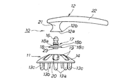
- FIG. 1 is a perspective view of a massage device according to a preferred embodiment of the present invention.
- FIG. 2 is an exploded side view of the massage device according to a preferred embodiment of the present invention.
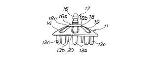
- FIG. 3 is a side view of a state in which the fixed pin portion is integrally attached to the massage main body portion.
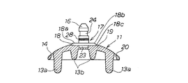
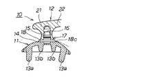
- FIG. 4 is a schematic cross-sectional view showing the fixing pin portion in a side view in a state where the fixing pin portion is integrally attached to the massage main body portion.
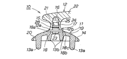
- FIG. 5 is a schematic cross-sectional view showing the fixed pin portion in a side view in a state where the grip portion is joined to the massage main body portion via the fixed pin portion.
- FIG. 6A is a schematic cross-sectional view showing a fixed pin portion in a side view for explaining a state in which the massage main body portion is elastically deformed when the massage tool according to a preferred embodiment of the present invention is used.
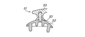
- FIG. 6B is a schematic cross-sectional view illustrating a state in which a gap is generated in the joint portion between the grip portion and the massage main body portion in the conventional massage device.
- FIG. 7 is an enlarged side view of the joining pin of the fixing pin portion.
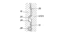
- FIG. 8 is an enlarged side view for explaining a preferable configuration for fitting and fixing the joining pin of the fixing pin portion to the fitting connection hole of the gripping portion.
- the gripping part for gripping the hairbrush as a massage tool must be preferably formed of a hard material.
- the deformation of the substrate made of a flexible material tends to cause a gap at the joint between the grip portion and the substrate (see FIG. 6B), and the hair is pulled out when the hair is caught in the gap. It is possible.
- the present invention makes it easy to sandwich hair by using a gap between the massage body substrate formed of a flexible material having elasticity and a grip portion formed of a hard material, preferably during use. It is related with the massage tool which can avoid this effectively.
- the present invention is a massage device having a massage body part, a grip part, and a fixed pin part.
- the massage body portion is made of a synthetic resin material having a plurality of pressing protrusions protruding downward from the inner side surface of the substrate and having an elastic force.
- the grip portion is made of a synthetic resin material.
- the fixing pin portion has an overhang base and a joining pin and is made of a synthetic resin material.
- the overhang base includes an upper joint surface having an outer peripheral edge shaped along the outer peripheral edge of the lower end joint surface of the grip portion, and the lower outer peripheral edge of the overhang base is fused to the massage main body.
- the fixing pin portion is integrally attached to the outer surface of the substrate.
- the joint pin protrudes from the outer surface of the substrate and is fitted into a fitting connection hole formed to open at the lower end joint surface of the grip portion, whereby the massage body portion, the grip portion, and the fixing pin The parts are integrated.
- a massage tool 10 according to a preferred embodiment of the present invention shown in FIG. 1 is massaged by a simple operation performed by gripping the grip portion 12 instead of massage to the head performed by pressing a finger against the scalp, for example.
- the massage device 10 of the present embodiment is configured such that when the massage main body 11 made of a synthetic resin material having an elastic force is elastically deformed, the massage main body 11 and the grip portion 12 made of a hard synthetic resin material are preferably used. It is provided with a function that prevents the hair from being caught by preventing a large gap 50 (see FIG. 6B) from occurring in the joint portion between them.
- the massage device 10 of this embodiment includes a plurality of pressing protrusions 13 a, 13 b, and 13 c that protrude downward from the inner surface of the substrate 14, and is a synthetic resin that has elastic force.
- the massage main body 11 made of a material, preferably the grip 12 made of a hard synthetic resin material, and attached to the outer surface of the substrate 14 as an integral unit, and formed to open at the lower end joint surface 12a of the grip 12
- the connecting pin 16 to be fitted into the fitting connection hole 15 protrudes from the center portion of the outer surface of the substrate 14, and preferably includes a fixing pin portion 17 preferably made of a hard synthetic resin material.
- the fixed pin portion 17 is provided with an overhang base 18 having an upper joint surface 18a having an outer peripheral edge portion 18b shaped along the outer peripheral edge portion 12b of the lower end joint surface 12a of the grip portion 12, and the fixed pin
- the portion 17 is integrally attached to the outer surface of the substrate 14 by fusing the lower outer peripheral edge portion 18c of the overhang base 18 to the massage body portion 11 by, for example, two-color molding or insert molding.
- the massage device 10 of the present embodiment has a massage main body part 11, a grip part 12, and a fixing pin part 17, and the massage main body part 11 has a plurality of presses protruding downward from the inner surface of the substrate 14. It has a projection 13a, 13b, 13c and is made of a synthetic resin material having an elastic force, the grip portion 12 is made of a synthetic resin material, and the fixing pin portion 17 has an overhanging base 18 and a joining pin 16, and is synthesized. Made of resin material.
- the overhang base 18 includes an upper joint surface 18 a having an outer peripheral edge portion 18 b shaped along the outer peripheral edge portion 12 b of the lower end joint surface 12 a of the grip portion 12, and a lower outer peripheral edge portion 18 c of the overhang base 18.
- the fixing pin 17 is integrally attached to the outer surface of the substrate 14 by being fused to the massage body 11.
- the joint pin 16 protrudes from the outer surface of the substrate 14 and is fitted into a fitting connection hole 15 formed in the lower end joint surface of the grip portion 12 so that the massage main body portion 11, the grip portion 12, and the fixing pin are inserted.
- the part 17 is integrated.
- the outer peripheral edge portion 18b of the upper joint surface 18a of the overhanging base 18 of the fixed pin portion 17 has a shape along the outer peripheral edge portion 12b of the lower end joint surface 12a of the grip portion 12.
- these shapes and sizes generally match. It is also included.
- the case where both are circular and the diameters thereof are slightly different, or the case where one is circular and the other is a polygon circumscribing or inscribed in the circular shape is also included.
- the massage main body 11 constituting the massage device 10 is preferably made of, for example, an elastomer (styrene-based, polyester-based, olefin-based) as a synthetic resin material having a considerable elastic force with an elastic modulus of about 10 to 30 MPa. , Urethane type, etc.).
- styrene elastomers are excellent in transparency and have a high degree of freedom in coloring, so that they can be preferably used.
- the substrate 14 of the massage main body 11 has a thickness of about 2 to 7 mm, for example, has a disk shape with a diameter of about 40 to 80 mm as a planar shape, and a curvature radius of about 40 to 80 mm, for example. It is formed into a flat bowl shape curved in a curved surface shape (dome shape) with a curvature of.
- the substrate 14 is provided with a tongue-like piece 19 extending outward from the central portion thereof, and a U-shaped through groove 20 provided around the base end portion on the central portion side.
- a plurality of cantilevers are provided at intervals in the circumferential direction in a state of projecting in a cantilever shape from the base end.
- Each tongue-like piece 19 is provided with a pressing projection 13a at the tip portion protruding downward.
- a central portion pressing protrusion 13b protruding downward is provided on the inner surface of the central portion of the substrate 12, and a portion between the pressing protrusions 13a adjacent in the circumferential direction is provided below.
- a protruding auxiliary pressing protrusion 13c is provided. The tips of these pressing protrusions 13a, 13b, and 13c are pressing portions formed in a hemispherical shape or a curved surface shape.
- the grip portion 12 constituting the massage device 10 is preferably harder than the massage main body portion 11 (that is, less likely to be deformed than the massage main body portion 11) and has an elastic modulus of 750 to 3600 MPa (more preferably 1200 to As a hard synthetic resin material having an elasticity equivalent to about 3300 MPa, more preferably about 1700 to 2500 MPa, for example, ABS (acrylonitrile-butadiene-styrene copolymer) resin, PBT (polybutylene terephthalate) resin, PP (polypropylene) resin PE (polyethylene) resin, PET (polyethylene terephthalate) resin, PCTA (polycyclohexanedimethylene terephthalate) resin, POM (polyacetal) resin, acrylic resin, AS (acrylic nitrile styrene copolymer) resin, It is formed using the S (polystyrene) resin or the like.
- ABS acrylonitrile-butadiene
- PCTA is preferably used because it has excellent transparency, a large degree of freedom in coloring, excellent chemical resistance, and high impact strength.
- the grip portion 12 is integrated with the massage main body portion 11 via the fixed pin portion 17, and a pressing force for pressing the pressing protrusions 13a, 13b, 13c against the scalp, a rotational force for squeezing the head, etc. Can be efficiently transmitted to the massage main body 11.
- the gripping portion 12 includes a joining drum portion 21 in which the entire circumference of the cylindrical body is a constricted portion, and protrudes radially outward from the upper portion of the joining drum portion 21 and extends in one direction.
- the handle portion 22 to be provided has a shape integrally formed.
- the lower end surface of the joining drum portion 21 constitutes the lower end joining surface 12a of the grip portion 12, and is arranged in close contact with the upper joining surface 18a of the overhang base 18 of the fixed pin portion 17.
- a fitting connection hole 15 having a circular hollow cross section that opens to the center portion of the lower end joining surface 12a of the grip portion 12 is formed in the joining drum portion 21.
- the joining pin 16 of the fixing pin portion 17 integrally joined to the outer surface of the substrate 14 of the massage main body portion 11 is fitted and attached in a state where it is difficult to remove.
- the fixed pin portion 17 constituting the massage device 10 can be fused to the massage body 11 and is preferably harder than the synthetic resin material of the massage body 11 and has an elastic modulus of 750 to 3600 MPa (more As a hard synthetic resin material having an elasticity equivalent to about 750 to 2100 MPa, more preferably about 800 to 2000 MPa, for example, ABS (acrylonitrile-butadiene-styrene copolymer) resin, PP (polypropylene) resin, PE (polyethylene) ) Resin, PET-G (a kind of polyethylene terephthalate) resin, POM (polyacetal) resin, acrylic resin, AS (acrylic nitrile styrene copolymer) resin, and the like.
- PP has a high degree of freedom in coloring and can be preferably used.
- the fixing pin portion 17 is made of, for example, a hard synthetic resin material that is softer than the synthetic resin material of the grip portion 12. Since the fixing pin portion 17 is formed of a synthetic resin material that is softer than the grip portion 12, when the joining pin 16 is driven or forcedly pushed into the fitting connection hole 15, the joining pin 16 is moved toward the fitting pin 16. By making the deformation, it becomes possible to make the fitting smoothly, and by such deformation, the adhesion between the outer peripheral surface of the joining pin 16 and the inner peripheral surface of the fitting connection hole 15 is improved. In addition, the massage body 11 and the grip 12 can be joined and integrated in a more stable state.
- the fixed pin portion 17 includes a disk-shaped overhang base 18, a joint pin 16 that stands integrally upward from the center portion of the overhang base 18, and a joint pin from the center portion of the overhang base 18. 16 and an embedded anchor 23 that protrudes integrally below the opposite side.
- the upper surface of the overhang base 18 includes a flat upper joint surface 18 a having an outer peripheral edge portion 18 b shaped along the outer peripheral edge portion 12 b of the lower end joint surface 12 a of the grip portion 12.
- the overhanging base 18 has a shape that expands from the upper surface toward the lower side in the thickness direction and expands toward the end, and has a flat lower surface.
- the fixing pin portion 17 is fusion-bonded to the massage main body portion 11 through the flat lower surface.
- the embedded anchor 23 is a portion having a flat columnar shape that protrudes downward from a central portion of the lower surface of the overhanging base 18.
- the embedded anchor 23 is embedded in the central portion of the outer surface of the substrate 14 of the massage main body 11 and exhibits an anchor function.
- the fixing pin portion 17 can be firmly joined and integrated with the massage main body portion 11.
- the joining pin 16 is a cylindrical projection having an outer shape similar to the inner diameter of the fitting connection hole 15 formed in the joining drum portion 21 of the gripping portion 12, which protrudes upward from the center portion of the upper surface of the overhang base 18. .
- the joining pin 16 has a length that fits in the fitting connection hole 15 as a whole, and the tip is chamfered in a tapered shape.
- the pin-side circumferential groove 24 is formed along the outer peripheral surface of the joining pin 16.
- the pin-side circumferential concave groove 24 has a grip-side circumferential convex rib 25 formed along the inner peripheral surface of the fitting connection hole 15 when the joining pin 16 is fitted into the fitting connection hole 15.
- a tapered surface portion 26 in which the inner diameter of the inner peripheral surface is gradually reduced toward the back side is provided in the back region of the fitting connection hole 15. It can also be left.
- the pin-side longitudinal groove 27 can be formed along the outer peripheral surface of the joining pin 16.
- a grip part-side vertical convex rib (not shown) formed along the inner peripheral surface of the fitting connection hole 15. Can be engaged. This makes it possible to avoid the grip portion 12 from rotating relative to the massage main body portion 11 when the massage tool 10 is used.
- a sealing ring 28 made of, for example, an elastomer can be attached along the outer peripheral surface of the proximal end portion of the joining pin 16.
- a sealing ring 28 for sealing for example, a hair washing agent or a hair styling agent is prevented from entering the fitting connection hole 15 to prevent mold from entering. Occurrence and the like can be effectively avoided.
- the fixing pin portion 17 and the massage main body portion 11 are fused and formed integrally by, for example, two-color molding or insert molding.
- the lower outer peripheral edge portion 18 c of the overhang base 18 of the fixing pin portion 17 is firmly fused and fixed to the outer surface of the substrate 14 without a gap.
- the massage main body portion 11 in which the fixing pin portion 17 is joined and integrated is fitted by pushing or forcibly pushing the joining pin 16 of the fixing pin portion 17 into the fitting connection hole 15 of the joining drum portion 21 of the grip portion 12.
- the massage device 10 is easily formed by being integrated with the grip portion 12.
- substrate 14 of the massage main-body part 11 formed with the flexible raw material provided with an elastic force Preferably it is a hard material. It is possible to effectively avoid the occurrence of a gap at the joint portion between the two and the hair, which makes it easy to sandwich the hair.
- the massage device 10 includes the massage main body portion 11, the grip portion 12, and the fixed pin portion 17, and the fixed pin portion 17 has an outer side of the lower end joint surface 12 a of the grip portion 12.
- An overhanging base 18 having an upper joint surface 18a having an outer peripheral edge 18b shaped along the peripheral edge 12b is provided, and the fixing pin 17 is used to massage the lower outer peripheral edge 18c of the overhanging base 18 into a massage body. Since it is fused to the portion 11 and is integrally attached to the outer surface of the substrate 14, the force from the grip portion 12 is effectively transmitted in a stable state to the massage body portion 11 via the fixed pin portion 17. It becomes possible.
- the massage main body 52 provided with an elastic force when used, and the grip part 53 made of, for example, a hard synthetic resin material, It is possible to effectively avoid the occurrence of a large gap 50 in the joint portion between the two and the hair being easily caught in the gap 50.
- the gripping portion does not necessarily have to be composed of a joining drum portion and a handle portion extending in one direction from the upper portion thereof, and may be a gripping portion composed of only a cylindrical portion, for example.
- the massage main body portion does not necessarily have to be provided with a tongue-like piece on the substrate, and may be one in which the pressing protrusion is directly projected from the inner surface of the substrate.
- a pin-side circumferential convex rib may be formed along the outer peripheral surface of the joining pin, and this may be engaged with a gripping portion-side circumferential concave groove formed along the inner peripheral surface of the fitting connection hole. Even if the pin-side vertical convex rib is formed along the outer peripheral surface of the joining pin, and this is engaged with the grip portion-side vertical concave groove formed along the inner peripheral surface of the fitting connection hole, good.
- the massage device of the present invention there is a gap at the time of use in the joint portion between the massage body substrate formed of a flexible material having elasticity and the grip portion preferably formed of a hard material. It can be effectively avoided that the hair is easily caught.
Landscapes
- Health & Medical Sciences (AREA)
- Dermatology (AREA)
- Epidemiology (AREA)
- Pain & Pain Management (AREA)
- Physical Education & Sports Medicine (AREA)
- Rehabilitation Therapy (AREA)
- Life Sciences & Earth Sciences (AREA)
- Animal Behavior & Ethology (AREA)
- General Health & Medical Sciences (AREA)
- Public Health (AREA)
- Veterinary Medicine (AREA)
- Massaging Devices (AREA)
Abstract
マッサージ本体部(10)、把持部(12)、及び固定ピン部(17)を有するマッサージ具であって、マッサージ本体部(10)は、複数の押圧突起(13a,13b,13c)を有すると共に弾性力を備える合成樹脂材料からなる。把持部(12)は、硬質の合成樹脂材料からなる。固定ピン部(17)は、張出し基台(18)と接合ピン(16)とを有すると共に合成樹脂材料からなる。張出し基台(18)は、把持部(12)の下端接合面(12a)と同様の形状の上部接合面(18a)を備える。張出し基台(18)の下部外周縁部(18c)をマッサージ本体部(10)に融着させて、固定ピン部(17)がマッサージ本体部(10)に一体として取り付けられる。接合ピン(16)が把持部(12)の下端接合面(12a)に形成された嵌合接続穴(15)に嵌め込まれることで、マッサージ本体部(10)、把持部(12)、及び固定ピン部(17)が一体化される。
Description
本発明は、マッサージ具に関し、特にマッサージ本体部、把持部、及び固定ピン部を有するマッサージ具に関する。
例えば、整髪や洗髪を行う際に、これらの整髪や洗髪と同時に頭部へのマッサージ効果を得ることが可能なヘアブラシが知られている(例えば、特許文献1参照)。特許文献1のヘアブラシは、把持部を備える曲面状に湾曲する扁平な椀状の基板の下面に、多数のブラシ突起を突設させたものである。特許文献1のヘアブラシは、扁平な椀状の基板や多数のブラシ突起を例えばエラストマーや合成ゴム等の弾性力を備える柔軟な素材で作成した場合には、頭部への押圧と押圧の解除を繰り返すことにより、特に基板の弾性変形によって、ブラシ突起によるマッサージ効果を高めることが可能になる。
本発明は、マッサージ本体部、把持部、及び固定ピン部を有するマッサージ具である。マッサージ本体部は、基板の内側面から下方に突出する複数の押圧突起を有すると共に、弾性力を備える合成樹脂材料からなる。把持部は合成樹脂材料からなる。固定ピン部は、張出し基台と接合ピンとを有すると共に、合成樹脂材料からなる。張出し基台は、前記把持部の下端接合面の外周縁部に沿った形状の外周縁部を有する上部接合面を備えると共に、該張出し基台の下部外周縁部を前記マッサージ本体部に融着させて、前記前記固定ピン部が前記基板の外側面に一体として取り付けられている。前記接合ピンは、前記基板の外側面から突出し、前記把持部の下端接合面に開口して形成された嵌合接続穴に嵌め込まれることにより、前記マッサージ本体部、前記把持部、及び前記固定ピン部が一体化されている。
扁平な椀状の基板を弾性力を備える柔軟な素材で形成した場合でも、マッサージ具としてのヘアブラシを把持するための把持部は、好ましくは硬質の素材で形成する必要があるため、ブラシの使用時に、柔軟な素材からなる基板の変形によって、把持部と基板との接合部分に隙間が生じやすくなり(図6(b)参照)、生じた隙間に髪の毛が挟まることで、髪の毛が抜けてしまうことが考えられる。
本発明は、弾性力を備える柔軟な素材で形成されたマッサージ本体部の基板と、好ましくは硬質の素材で形成された把持部との接合部分に、使用時に隙間が生じて髪の毛を挟み込み易くなるのを効果的に回避することのできるマッサージ具に関する。
本発明は、マッサージ本体部、把持部、及び固定ピン部を有するマッサージ具である。マッサージ本体部は、基板の内側面から下方に突出する複数の押圧突起を有すると共に、弾性力を備える合成樹脂材料からなる。把持部は合成樹脂材料からなる。固定ピン部は、張出し基台と接合ピンとを有すると共に、合成樹脂材料からなる。張出し基台は、前記把持部の下端接合面の外周縁部に沿った形状の外周縁部を有する上部接合面を備えると共に、該張出し基台の下部外周縁部を前記マッサージ本体部に融着させて、前記前記固定ピン部が前記基板の外側面に一体として取り付けられている。前記接合ピンは、前記基板の外側面から突出し、前記把持部の下端接合面に開口して形成された嵌合接続穴に嵌め込まれることにより、前記マッサージ本体部、前記把持部、及び前記固定ピン部が一体化されている。
図1に示す本発明の好ましい一実施形態に係るマッサージ具10は、例えば頭皮に指を押し当てて行う頭部へのマッサージに代えて、把持部12を把持して行う簡単な操作により、マッサージ本体部11の押圧突起13a,13b,13cを頭皮に押し付けたり擦り付けたりすることによって、好ましくは髪の毛を直接手で触れることなく、指でマッサージを行った場合と同等のマッサージ効果が得られるようにするものである。また、本実施形態のマッサージ具10は、弾性力を備える合成樹脂材料からなるマッサージ本体部11が弾性変形した際に、マッサージ本体部11と好ましくは硬質の合成樹脂材料からなる把持部12との間の接合部分に大きな隙間50(図6(b)参照)が生じないようにして、毛が挟み込まれるのを回避できる機能を備える。
そして、本実施形態のマッサージ具10は、図2~図5にも示すように、基板14の内側面から下方に突出する複数の押圧突起13a,13b,13cを有する、弾性力を備える合成樹脂材料からなるマッサージ本体部11と、好ましくは硬質の合成樹脂材料からなる把持部12と、基板14の外側面に一体として取り付けられて、把持部12の下端接合面12aに開口して形成された嵌合接続穴15(図5参照)に嵌め込まれる接合ピン16を基板14の外側面の好ましくは中央部分から突出させる、好ましくは硬質の合成樹脂材料からなる固定ピン部17とを含んで構成される。固定ピン部17には、把持部12の下端接合面12aの外周縁部12bに沿った形状の外周縁部18bを有する上部接合面18aを備える張出し基台18が設けられており、且つ固定ピン部17は、張出し基台18の下部外周縁部18cをマッサージ本体部11に例えば2色成形やインサート成形により融着させて、基板14の外側面に一体として取り付けられている。
すなわち、本実施形態のマッサージ具10は、マッサージ本体部11、把持部12、及び固定ピン部17を有しており、マッサージ本体部11は、基板14の内側面から下方に突出する複数の押圧突起13a,13b,13cを有すると共に、弾性力を備える合成樹脂材料からなり、把持部12は合成樹脂材料からなり、固定ピン部17は、張出し基台18と接合ピン16とを有すると共に、合成樹脂材料からなっている。張出し基台18は、把持部12の下端接合面12aの外周縁部12bに沿った形状の外周縁部18bを有する上部接合面18aを備えると共に、当該張出し基台18の下部外周縁部18cをマッサージ本体部11に融着させて、固定ピン部17が基板14の外側面に一体として取り付けられている。接合ピン16は、基板14の外側面から突出し、把持部12の下端接合面に開口して形成された嵌合接続穴15に嵌め込まれることにより、マッサージ本体部11、把持部12、及び固定ピン部17が一体化されている。
ここで、固定ピン部17の張出し基台18の上部接合面18aの外周縁部18bが、把持部12の下端接合面12aの外周縁部12bに沿った形状を有しているということには、上部接合面18aの外周縁部18bの形状及び大きさと下端接合面12aの外周縁部12bの形状及び大きさとが合致していることの他、これらの形状及び大きさが概ね合致していることも含まれる。例えば、双方が共に円形であって、その直径が僅かに異なる場合や、一方が円形であって、他方がこの円形に外接又は内接する多角形である場合等も含まれる。
本実施形態では、マッサージ具10を構成するマッサージ本体部11は、好ましくは弾性率が10~30MPa程度の相当の弾性力を備える合成樹脂材料として、例えば、エラストマー(スチレン系、ポリエステル系、オレフィン系、ウレタン系など)等を用いて形成される。特にスチレン系エラストマーは透明性に優れるものがあり、着色の自由度も大きいため、好ましく使用することができる。マッサージ本体部11の基板14は、例えば2~7mm程度の厚さを有すると共に、平面形状として直径が例えば40~80mm程度の円板形状を有しており、また曲率半径が例えば40~80mm程度の曲率で曲面状(ドーム状)に湾曲した扁平な椀状に形成される。
また、本実施形態では、基板14には、これの中央部分から外側に向けて延設する舌状片19が、中央部分側の基端部を除く周囲にU字状の貫通溝20が設けられることにより基端部から片持ち梁状に張り出した状態で、周方向に間隔をおいて複数設けられている。各々の舌状片19の先端部分には、下方に突出して押圧突起13aが設けられている。さらに、本実施形態では、基板12の中央部分の内側面に、下方に突出する中央部押圧突起13bが設けられており、また周方向に隣接する押圧突起13aの間の部分には、下方に突出する補助押圧突起13cが設けられている。これらの押圧突起13a,13b,13cの先端は、半球形状又は曲面形状に形成された押圧部となっている。
マッサージ具10を構成する把持部12は、本実施形態では、好ましくはマッサージ本体部11よりも硬い(すなわちマッサージ本体部11よりも変形し難い)、弾性率が750~3600MPa(より好ましくは1200~3300MPa、更に好ましくは1700~2500MPa)程度相当の弾性力を備える硬質の合成樹脂材料として、例えばABS(アクリロニトリル・ブタジエン・スチレン共重合体)樹脂、PBT(ポリブチレンテレフタレート)樹脂、PP(ポリプロピレン)樹脂、PE(ポリエチレン)樹脂、PET(ポリエチレンテレフタレート)樹脂、PCTA(ポリシクロヘキサンジメチレンテレフタレート)樹脂、POM(ポリアセタール)樹脂、アクリル樹脂、AS(アクリル二トリルスチレン共重合体)樹脂、PS(ポリスチレン)樹脂等を用いて形成される。特にPCTAは、透明性に優れ、着色の自由度が大きく、耐薬品性に優れ、衝撃強度の高いものがあるので好ましく使用することができる。把持部12は、固定ピン部17を介してマッサージ本体部11と一体化されて、押圧突起13a,13b,13cを頭皮に押し当てるための押圧力や、頭部を揉み解すための回転力等を、マッサージ本体部11に効率良く伝達できるようになっている。
また、本実施形態では、把持部12は、円筒体の周面全周がくびれ部となっている接合ドラム部21と、この接合ドラム部21の上部から径方向外側に張り出して一方向に延設するハンドル部22とが一体成形された形状を有している。これによって、マッサージ具10を用いて頭部へのマッサージを行う際に、圧迫法、強擦法、揉捏法、軽擦法、打突法等のマッサージの方法や、マッサージを行なう部位や力加減に応じて、種々の持ち方から適切な持ち方を選択することが可能になる。またこれによりマッサージ効果を得るための操作を安定した状態で行って、効率良く且つ効果的にマッサージを行うことが可能になる。
さらに、本実施形態では、接合ドラム部21の下端面が把持部12の下端接合面12aを構成していて、固定ピン部17の張出し基台18の上部接合面18aと密着配置されるようになっていると共に、把持部12の下端接合面12aの中央部分に開口して、円形の中空断面を有する嵌合接続穴15が、接合ドラム部21の内部に形成されている。この嵌合接続穴15には、マッサージ本体部11の基板14の外側面に一体として接合された固定ピン部17の接合ピン16が、取り外すことが困難な状態で嵌合装着される。
マッサージ具10を構成する固定ピン部17は、本実施形態では、マッサージ本体部11と融着可能で、且つ好ましくはマッサージ本体部11の合成樹脂材料よりも硬い、弾性率が750~3600MPa(より好ましくは750~2100MPa、更に好ましくは800~2000MPa)程度相当の弾性力を備える硬質の合成樹脂材料として、例えばABS(アクリロニトリル・ブタジエン・スチレン共重合体)樹脂、PP(ポリプロピレン)樹脂、PE(ポリエチレン)樹脂、PET-G(ポリエチレンテレフタレートの一種)樹脂、POM(ポリアセタール)樹脂、アクリル樹脂、AS(アクリル二トリルスチレン共重合体)樹脂等を用いて形成される。特にPPは着色の自由度が高く好ましく使用することができる。
また、固定ピン部17は、把持部12の合成樹脂材料よりも軟らかい例えば硬質の合成樹脂材料によって形成されていることが好ましい。固定ピン部17が把持部12よりも軟らかい合成樹脂材料によって形成されていることにより、接合ピン16を打ち込んだり無理押しして嵌合接続穴15に嵌め込む際に、当該接合ピン16の方を変形させることで、嵌め込みがスムーズに行われるようにすることが可能になると共に、このような変形によって接合ピン16の外周面と嵌合接続穴15の内周面との密着性を向上させて、さらに安定した状態でマッサージ本体部11と把持部12とを接合一体化することが可能になる。
本実施形態では、固定ピン部17は、円盤形状の張出し基台18と、張出し基台18の中央部分から上方に一体として立設する接合ピン16と、張出し基台18の中央部分から接合ピン16とは反対側の下方に一体として突出する、埋込みアンカー23とによって構成される。張出し基台18の上面は、把持部12の下端接合面12aの外周縁部12bに沿った形状の外周縁部18bを有する、平坦な上部接合面18aを備えている。固定ピン部17を介して把持部12と固定ピン部17とを接合一体化させた際に、把持部12の下端接合面12aと張出し基台18の上部接合面18aとを強固に密着させて、把持部12からの力をマッサージ本体部11に安定した状態で伝達させることが可能になる。また、張出し基台18は、上面から厚さ方向下方に向けて末広がりに拡径する形状を備えると共に、平坦な下面を有している。この平坦な下面を介して、固定ピン部17がマッサージ本体部11と融着接合される。
埋込みアンカー23は、張出し基台18の下面中央部分から下方に突出する、扁平な円柱形状を備える部分である。埋込みアンカー23は、例えば2色成形やインサート成形によってマッサージ本体部11が形成される際に、マッサージ本体部11の基板14の外側面の中央部分に埋設されて、アンカー機能を発揮することで、固定ピン部17をマッサージ本体部11に強固に接合一体化させることが可能になる。
接合ピン16は、張出し基台18の上面中央部分から上方に突出する、把持部12の接合ドラム部21に形成された嵌合接続穴15の内径と同様の外形を有する円柱形状の突起である。接合ピン16は、その全体が嵌合接続穴15に収まる長さを備えると共に、先端が先細状に面取りされている。
本実施形態では、接合ピン16の外周面に沿って、ピン側周方向凹溝24が形成されている。このピン側周方向凹溝24には、接合ピン16の嵌合接続穴15への嵌め込み時に、嵌合接続穴15の内周面に沿って形成された把持部側周方向凸リブ25が係合される。これによって、把持部12とマッサージ本体部11とを更に強固に接合一体化することが可能になる。
なお、本実施形態では、図8に示すように、嵌合接続穴15の奥部領域には、内周面の内径を奥部側に向けて徐々に縮径させたテーパー面部26を設けておくこともできる。嵌合接続穴15の奥部領域にテーパー面部26を設けておくことにより、接合ピン16の嵌合接続穴15への嵌め込み時に、接合ピン16の先端部分のストレート形状の外周面を、テーパー面部26に食い込ませて楔効果を発揮させることにより、把持部12とマッサージ本体部11とを更に強固に接合一体化することが可能になる。
また、本実施形態では、図7に示すように、接合ピン16の外周面に沿って、ピン側縦方向凹溝27を形成しておくこともできる。このピン側縦方向凹溝27には、接合ピン16の嵌合接続穴15への嵌め込み時に、嵌合接続穴15の内周面に沿って形成された把持部側縦方向凸リブ(図示せず)を係合することができる。これによって、マッサージ具10の使用時に、マッサージ本体部11に対して把持部12が相対的に回転するのを回避することが可能になる。
さらに、本実施形態では、図8に示すように、接合ピン16の基端部分の外周面に沿って、例えばエラストマーからなる密閉用シールリング28を取り付けておくことができる。この密閉用シールリング28によって嵌合接続穴15の内周面との隙間をシールすることで、嵌合接続穴15の内部に例えば洗髪剤や整髪剤が侵入するのを遮断して、カビの発生等を効果的に回避することが可能になる。
本実施形態では、固定ピン部17とマッサージ本体部11とは、例えば2色成形やインサート成形によって形成されることにより融着されて、強固に接合一体化される。これによって、固定ピン部17の張出し基台18の下部外周縁部18cは、基板14の外側面に隙間無く強固に融着固定される。また、固定ピン部17が接合一体化されたマッサージ本体部11は、固定ピン部17の接合ピン16を、把持部12の接合ドラム部21の嵌合接続穴15に打ち込んだり無理押しして嵌め込むことにより把持部12と一体化されて、マッサージ具10が容易に形成される。
そして、上述の構成を有する本実施形態のマッサージ具10によれば、弾性力を備える柔軟な素材で形成されたマッサージ本体部11の基板14と、好ましくは硬質の素材で形成された把持部12との接合部分に、使用時に隙間が生じて髪の毛を挟み込み易くなるのを効果的に回避することが可能になる。
すなわち、本実施形態によれば、マッサージ具10は、マッサージ本体部11と、把持部12と、固定ピン部17とからなり、固定ピン部17には、把持部12の下端接合面12aの外周縁部12bに沿った形状の外周縁部18bを有する上部接合面18aを備える張出し基台18が設けられており、且つ固定ピン部17は、張出し基台18の下部外周縁部18cをマッサージ本体部11に融着させて、基板14の外側面に一体として取り付けられているので、把持部12からの力を固定ピン部17を介してマッサージ本体部11に安定した状態で効果的に伝達することが可能になる。また、固定ピン部17の張出し基台18の下部外周縁部18cがマッサージ本体部11の基板14の外側面に隙間無く強固に融着しているので、図6(a)に示すように、マッサージ具10の使用時にマッサージ本体部11の基板14が変形しても、固定ピン部17の張出し基台18とマッサージ本体部11の基板14の外側面との間に隙間が生じることがない。
したがって、本実施形態によれば、例えば図6(b)に示す従来のマッサージ具51のように、使用時に弾性力を備えるマッサージ本体部52と、例えば硬質の合成樹脂材料からなる把持部53との間の接合部分に大きな隙間50が生じて、この隙間50に毛が挟み込まれ易くなるのを効果的に回避することが可能になる。
なお、本発明は上記実施形態に限定されることなく種々の変更が可能である。例えば、把持部は、接合ドラム部とこれの上部から一方向に延設するハンドル部とからなるものである必要は必ずしもなく、例えば円筒体の部分のみからなる把持部であっても良い。また、マッサージ本体部は、基板に舌状片を設けたものである必要は必ずしも無く、基板の内側面から押圧突起を直接突出させたものであっても良い。さらに、接合ピンの外周面に沿ってピン側周方向凸リブを形成して、これを嵌合接続穴の内周面に沿って形成された把持部側周方向凹溝に係合させても良く、接合ピンの外周面に沿ってピン側縦方向凸リブを形成して、これを嵌合接続穴の内周面に沿って形成された把持部側縦方向凹溝に係合させても良い。
本発明のマッサージ具によれば、弾性力を備える柔軟な素材で形成されたマッサージ本体部の基板と、好ましくは硬質の素材で形成された把持部との接合部分に、使用時に隙間が生じて髪の毛を挟み込み易くなるのを効果的に回避することができる。
Claims (7)
- マッサージ本体部、把持部、及び固定ピン部を有するマッサージ具であって、
前記マッサージ本体部は、基板の内側面から下方に突出する複数の押圧突起を有すると共に、弾性力を備える合成樹脂材料からなり、
前記把持部は合成樹脂材料からなり、
前記固定ピン部は、張出し基台と接合ピンとを有すると共に、合成樹脂材料からなり、
該張出し基台は、前記把持部の下端接合面の外周縁部に沿った形状の外周縁部を有する上部接合面を備えると共に、該張出し基台の下部外周縁部を前記マッサージ本体部に融着させて、前記前記固定ピン部が前記基板の外側面に一体として取り付けられており、
前記接合ピンは、前記基板の外側面から突出し、前記把持部の下端接合面に開口して形成された嵌合接続穴に嵌め込まれることにより、前記マッサージ本体部、前記把持部、及び前記固定ピン部が一体化されているマッサージ具。 - 前記固定ピン部の合成樹脂材料が、前記把持部の合成樹脂材料よりも軟らかい合成樹脂材料である請求項1記載のマッサージ具。
- 前記固定ピン部の合成樹脂材料が、前記マッサージ本体部の合成樹脂材料よりも硬い合成樹脂材料である請求項1又は2記載のマッサージ具。
- 前記接合ピンの外周面に沿って、ピン側周方向凹溝又はピン側周方向凸リブが形成されており、前記嵌合接続穴の内周面に沿って、前記接合ピンの前記嵌合接続穴への嵌め込み時に前記ピン側周方向凹溝又はピン側周方向凸リブに係合される、把持部側周方向凸リブ又は把持部側周方向凹溝が形成されている請求項1~3の何れか1項記載のマッサージ具。
- 前記嵌合接続穴の奥部領域には、内周面の内径を奥部側に向けて徐々に縮径させたテーパー面部が設けられている請求項1~4の何れか1項記載のマッサージ具。
- 前記接合ピンの外周面に沿って、ピン側縦方向凹溝又はピン側縦方向凸リブが形成されており、前記嵌合接続穴の内周面に沿って、前記接合ピンの前記嵌合接続穴への嵌め込み時に前記ピン側縦方向凹溝又はピン側縦方向凸リブに係合される、把持部側縦方向凸リブ又は把持部側縦方向凹溝が形成されている請求項1~5の何れか1項記載のマッサージ具。
- 前記固定ピン部は、前記張出し基台から前記接合ピンとは反対側に突出する埋込みアンカーを備えており、該埋込みアンカーは、前記マッサージ本体部の前記基板に埋設される請求項1~6の何れか1項記載のマッサージ具。
Priority Applications (1)
| Application Number | Priority Date | Filing Date | Title |
|---|---|---|---|
| CN201180050902.0A CN103179938B (zh) | 2010-10-20 | 2011-10-19 | 按摩具 |
Applications Claiming Priority (2)
| Application Number | Priority Date | Filing Date | Title |
|---|---|---|---|
| JP2010-235675 | 2010-10-20 | ||
| JP2010235675 | 2010-10-20 |
Publications (1)
| Publication Number | Publication Date |
|---|---|
| WO2012053538A1 true WO2012053538A1 (ja) | 2012-04-26 |
Family
ID=45975249
Family Applications (1)
| Application Number | Title | Priority Date | Filing Date |
|---|---|---|---|
| PCT/JP2011/074016 Ceased WO2012053538A1 (ja) | 2010-10-20 | 2011-10-19 | マッサージ具 |
Country Status (3)
| Country | Link |
|---|---|
| JP (1) | JP5269967B2 (ja) |
| CN (1) | CN103179938B (ja) |
| WO (1) | WO2012053538A1 (ja) |
Families Citing this family (2)
| Publication number | Priority date | Publication date | Assignee | Title |
|---|---|---|---|---|
| CN112168637A (zh) * | 2019-07-02 | 2021-01-05 | 林靖琳 | 经络按摩手持设备 |
| KR102686055B1 (ko) * | 2022-11-18 | 2024-07-16 | 조정헌 | 다목적용 바디 브러시 |
Citations (4)
| Publication number | Priority date | Publication date | Assignee | Title |
|---|---|---|---|---|
| JPH03113002U (ja) * | 1990-03-01 | 1991-11-19 | ||
| JPH07116026A (ja) * | 1993-10-26 | 1995-05-09 | Meito:Kk | 毛髪用ブラシアタッチメント |
| JP2009240768A (ja) * | 2008-03-12 | 2009-10-22 | Kao Corp | 頭皮マッサージ用ブラシ |
| WO2011034076A1 (ja) * | 2009-09-17 | 2011-03-24 | 花王株式会社 | マッサージブラシ及びマッサージブラシ用ハンドル |
Family Cites Families (1)
| Publication number | Priority date | Publication date | Assignee | Title |
|---|---|---|---|---|
| JP3113002U (ja) * | 2005-05-02 | 2005-09-02 | 勝義 高藤 | 頭皮洗浄ブラシ |
-
2011
- 2011-10-19 WO PCT/JP2011/074016 patent/WO2012053538A1/ja not_active Ceased
- 2011-10-19 CN CN201180050902.0A patent/CN103179938B/zh not_active Expired - Fee Related
- 2011-10-19 JP JP2011229662A patent/JP5269967B2/ja active Active
Patent Citations (4)
| Publication number | Priority date | Publication date | Assignee | Title |
|---|---|---|---|---|
| JPH03113002U (ja) * | 1990-03-01 | 1991-11-19 | ||
| JPH07116026A (ja) * | 1993-10-26 | 1995-05-09 | Meito:Kk | 毛髪用ブラシアタッチメント |
| JP2009240768A (ja) * | 2008-03-12 | 2009-10-22 | Kao Corp | 頭皮マッサージ用ブラシ |
| WO2011034076A1 (ja) * | 2009-09-17 | 2011-03-24 | 花王株式会社 | マッサージブラシ及びマッサージブラシ用ハンドル |
Also Published As
| Publication number | Publication date |
|---|---|
| CN103179938B (zh) | 2015-04-22 |
| JP5269967B2 (ja) | 2013-08-21 |
| CN103179938A (zh) | 2013-06-26 |
| JP2012105965A (ja) | 2012-06-07 |
Similar Documents
| Publication | Publication Date | Title |
|---|---|---|
| JP5689613B2 (ja) | マッサージブラシ及びマッサージブラシ用ハンドル | |
| US20220354627A1 (en) | Electrical appliance for personal care | |
| TWI458453B (zh) | Scalp massage brush | |
| JP2020018870A (ja) | 歯ブラシ | |
| JP5269967B2 (ja) | マッサージ具 | |
| JP5665917B2 (ja) | マッサージ具 | |
| KR200443540Y1 (ko) | 안마기용 안마구의 각도 조절장치 | |
| WO2017208488A1 (ja) | 歯ブラシ | |
| TWI532451B (zh) | 洗臉用電動刷裝置 | |
| JP6478384B2 (ja) | 歯ブラシ用ハンドル体及び歯ブラシ | |
| JP2019115470A (ja) | 電動歯ブラシ用替えブラシ | |
| TWI527536B (zh) | 牙刷 | |
| JP6401538B2 (ja) | マッサージブラシ | |
| CN223601031U (zh) | 固定刷头的化妆刷结构 | |
| JP2015002817A (ja) | マッサージ具 | |
| JP7619804B2 (ja) | 塗布用ブラシ | |
| WO2018088512A1 (ja) | 歯ブラシ | |
| JP2024065493A (ja) | ブラシ | |
| JP2025073175A (ja) | ブラシ | |
| JP2018078988A (ja) | 洗髪用ブラシ | |
| JP2023034506A (ja) | 頭皮洗浄用ブラシ | |
| JP2016119947A (ja) | ヘアブラシ | |
| JP2017108895A (ja) | マッサージブラシ | |
| JP2018094008A (ja) | 歯ブラシと歯ブラシの製造方法 | |
| JP2018202004A (ja) | 幼児用歯ブラシ |
Legal Events
| Date | Code | Title | Description |
|---|---|---|---|
| 121 | Ep: the epo has been informed by wipo that ep was designated in this application |
Ref document number: 11834377 Country of ref document: EP Kind code of ref document: A1 |
|
| NENP | Non-entry into the national phase |
Ref country code: DE |
|
| 122 | Ep: pct application non-entry in european phase |
Ref document number: 11834377 Country of ref document: EP Kind code of ref document: A1 |