WO2012053215A1 - 冷却装置および原子力蒸気供給システム - Google Patents
冷却装置および原子力蒸気供給システム Download PDFInfo
- Publication number
- WO2012053215A1 WO2012053215A1 PCT/JP2011/005878 JP2011005878W WO2012053215A1 WO 2012053215 A1 WO2012053215 A1 WO 2012053215A1 JP 2011005878 W JP2011005878 W JP 2011005878W WO 2012053215 A1 WO2012053215 A1 WO 2012053215A1
- Authority
- WO
- WIPO (PCT)
- Prior art keywords
- liquid metal
- space
- outer container
- inlet
- tube
- Prior art date
- Legal status (The legal status is an assumption and is not a legal conclusion. Google has not performed a legal analysis and makes no representation as to the accuracy of the status listed.)
- Ceased
Links
Images



Classifications
-
- G—PHYSICS
- G21—NUCLEAR PHYSICS; NUCLEAR ENGINEERING
- G21D—NUCLEAR POWER PLANT
- G21D1/00—Details of nuclear power plant
- G21D1/006—Details of nuclear power plant primary side of steam generators
-
- F—MECHANICAL ENGINEERING; LIGHTING; HEATING; WEAPONS; BLASTING
- F22—STEAM GENERATION
- F22B—METHODS OF STEAM GENERATION; STEAM BOILERS
- F22B1/00—Methods of steam generation characterised by form of heating method
- F22B1/02—Methods of steam generation characterised by form of heating method by exploitation of the heat content of hot heat carriers
- F22B1/06—Methods of steam generation characterised by form of heating method by exploitation of the heat content of hot heat carriers the heat carrier being molten; Use of molten metal, e.g. zinc, as heat transfer medium
- F22B1/063—Methods of steam generation characterised by form of heating method by exploitation of the heat content of hot heat carriers the heat carrier being molten; Use of molten metal, e.g. zinc, as heat transfer medium for metal cooled nuclear reactors
-
- F—MECHANICAL ENGINEERING; LIGHTING; HEATING; WEAPONS; BLASTING
- F22—STEAM GENERATION
- F22B—METHODS OF STEAM GENERATION; STEAM BOILERS
- F22B21/00—Water-tube boilers of vertical or steeply-inclined type, i.e. the water-tube sets being arranged vertically or substantially vertically
- F22B21/22—Water-tube boilers of vertical or steeply-inclined type, i.e. the water-tube sets being arranged vertically or substantially vertically built-up from water tubes of form other than straight or substantially straight
- F22B21/28—Water-tube boilers of vertical or steeply-inclined type, i.e. the water-tube sets being arranged vertically or substantially vertically built-up from water tubes of form other than straight or substantially straight bent spirally
-
- G—PHYSICS
- G21—NUCLEAR PHYSICS; NUCLEAR ENGINEERING
- G21D—NUCLEAR POWER PLANT
- G21D1/00—Details of nuclear power plant
- G21D1/04—Pumping arrangements
-
- Y—GENERAL TAGGING OF NEW TECHNOLOGICAL DEVELOPMENTS; GENERAL TAGGING OF CROSS-SECTIONAL TECHNOLOGIES SPANNING OVER SEVERAL SECTIONS OF THE IPC; TECHNICAL SUBJECTS COVERED BY FORMER USPC CROSS-REFERENCE ART COLLECTIONS [XRACs] AND DIGESTS
- Y02—TECHNOLOGIES OR APPLICATIONS FOR MITIGATION OR ADAPTATION AGAINST CLIMATE CHANGE
- Y02E—REDUCTION OF GREENHOUSE GAS [GHG] EMISSIONS, RELATED TO ENERGY GENERATION, TRANSMISSION OR DISTRIBUTION
- Y02E30/00—Energy generation of nuclear origin
Definitions
- the present invention relates to a cooling device for cooling a liquid metal with a cooling medium and a nuclear steam supply system using the same.
- the primary coolant as the reactor coolant has a high level of radioactivity, so the primary cooling system and the steam generation system are isolated.
- the steam generation system heat exchange between the liquid metal and water is indispensable, but the chemical reaction heat generated by the contact between the two is enormous and must be dissipated. Therefore, it is usual to install a secondary cooling system between the primary cooling system and the steam generation system.
- the cooling device for a liquid metal cooled nuclear reactor includes, for example, a reactor vessel, a pump built-in intermediate heat exchanger, a steam generator, and a mechanical pump.
- this cooling device there is a cost for exchanging the consumable / deteriorating member of the movable part of the mechanical pump.
- a space for drawing a pipe connecting the steam generator and the mechanical pump is required.
- This electromagnetic pump can eliminate piping by making it an integral structure with a steam generator, for example.
- an object of the present invention is to enable easy inspection and repair of an electromagnetic pump in a cooling device that circulates liquid metal with an electromagnetic pump.
- the present invention provides a cooling device for cooling a liquid metal with a cooling medium, in which an opening, an inlet and an outlet for the liquid metal, and an inlet and an outlet for the cooling medium are formed.
- a partition for partitioning a heat transfer tube extending from the inlet to the outlet in the first space, an outward path communicating with the first space toward the opening, and an end portion of the forward path And a structure that divides into a return path extending to the discharge port, and an electromagnetic pump that is disposed in the second space and allows the liquid metal to flow from the forward path toward the return path.
- the present invention provides a nuclear reactor steam supply system, a reactor vessel containing a core, a cooling system that cools the core by heating the liquid metal with heat generated in the core, an opening, and the liquid metal
- An outer container in which an inlet and an outlet, a water inlet and an outlet are formed, a lid for closing the opening, and a first space facing the inlet, the inlet, and the outlet inside the outer container
- a partition that divides into a second space facing the opening and the outlet, a heat transfer tube extending from the inlet to the outlet in the first space, and communicating the second space with the first space
- a structure that divides into a forward path extending toward the opening and a return path extending from the end portion of the forward path to the discharge port, and the liquid metal disposed in the second space from the forward path toward the return path.
- the present invention it is possible to easily check and repair the electromagnetic pump in the cooling device that circulates the liquid metal with the electromagnetic pump.
- FIG. 6 is an elevational sectional view taken along arrows II in FIGS. 2 to 5, showing an elevational section of the first embodiment of the cooling device according to the present invention.
- FIG. 2 is a horizontal sectional view taken along the line II-II in FIG. 1.
- FIG. 3 is a horizontal sectional view taken along arrows III-III in FIG. 1.
- FIG. 4 is a horizontal sectional view taken along the line IV-IV in FIG. 1.
- FIG. 5 is a horizontal sectional view taken along the line VV in FIG. 1.
- 1 is a block diagram of a liquid metal cooled nuclear steam generation system using a first embodiment of a cooling device according to the present invention.
- FIG. 10 is an elevational sectional view taken along arrows VII-VII in FIGS.
- FIG. 8 is a horizontal sectional view taken along arrow VIII-VIII in FIG. 7.
- FIG. 8 is a horizontal sectional view taken along arrow IX-IX in FIG. 7.
- FIG. 6 is a block diagram of a liquid metal cooled nuclear steam generation system using the first embodiment of the cooling device according to the present invention.
- the liquid metal cooled nuclear steam generation system of the present embodiment includes a reactor vessel 1, an intermediate heat exchanger 2, and a cooling device 3. Inside the reactor vessel 1, a reactor core is housed. A primary cooling system 61 is provided between the reactor vessel 1 and the intermediate heat exchanger 2. A secondary cooling system 62 is provided between the intermediate heat exchanger 2 and the cooling device 3. Liquid metal circulates in the primary cooling system 61 and the secondary cooling system 62.
- the intermediate heat exchanger 2 incorporates a pump that circulates liquid metal.
- the heat generated in the reactor is recovered by the liquid metal circulating in the primary cooling system 61.
- the liquid metal recovered from the heat generated in the reactor of the primary cooling system 61 is cooled by exchanging heat with the liquid metal circulating in the secondary cooling system 62 in the intermediate heat exchanger 2.
- the liquid metal cooled by the intermediate heat exchanger 2 of the primary cooling system 61 returns to the reactor vessel 1 and is used again for cooling the reactor.
- the liquid metal in the secondary cooling system 62 that exchanges heat with the liquid metal in the primary cooling system 61 in the intermediate heat exchanger 2 heats water in the cooling device 3. That is, in the cooling device 3, the liquid metal is cooled by water that is a cooling medium. The water heated by the cooling device 3 becomes steam and is sent to a power generation turbine (not shown). The steam that has driven the power generation turbine is condensed by a condenser (not shown) and returns to the cooling device 3. The liquid metal of the secondary cooling system 62 cooled by exchanging heat with water in the cooling device 3 returns to the intermediate heat exchanger 2.
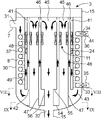
- FIG. 1 is an elevational sectional view taken along arrows II of FIGS. 2 to 5 showing an elevational section of the cooling device in the present embodiment.
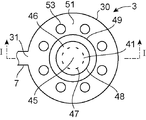
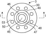
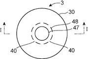
- FIG. 2 is a horizontal sectional view taken along the line II-II in FIG. 3 is a horizontal sectional view taken along the line III-III in FIG.
- FIG. 4 is a horizontal sectional view taken along the line IV-IV in FIG.
- FIG. 5 is a horizontal sectional view taken along line VV in FIG.
- the cooling device 3 has a cylindrical outer container 30.
- the outer container 30 is, for example, a cylinder arranged so that its axis is in the vertical direction. In addition, you may arrange
- the open end of the outer container 30 is closed with a lid 15.
- the lid 15 is fixed to the outer container 30 using, for example, screws.
- the lid 15 may be fixed to the outer container 30 via a bellows to absorb thermal expansion.
- An inlet 31 is formed on the side surface of the outer container 30.
- the inflow pipe 7 is connected to the inflow port 31.
- a discharge port 32 is formed at the closed end of the outer container 30.
- a discharge pipe 14 is attached to the discharge port 32.
- the inflow pipe 7 and the exhaust pipe 14 are part of the secondary cooling system 62.
- the liquid metal heated by the intermediate heat exchanger 2 flows through the inflow pipe 7.
- Liquid metal that returns to the intermediate heat exchanger 2 flows through the discharge pipe 14.
- an inlet 33 and an outlet 34 are formed on the side surface of the outer container 30.
- the inlet 31, the outlet 34, and the inlet 33 are formed at positions in order from the top to the bottom.
- a water supply pipe 35 is attached to the inlet 33.
- a steam pipe 36 is attached to the outlet 34.
- Water condensed by the condenser flows through the water supply pipe 35.
- the steam sent to the power generation turbine flows through the steam pipe 36.
- a partition tube 49 is provided inside the outer container 30.
- the partition tube 49 is, for example, a cylinder disposed coaxially with the outer container 30.
- a space inside the outer container 30 is partitioned by a partition tube 49 into an outer annular first space and an inner columnar second space.
- An annular space outside the partition tube 49 faces the inflow port 31 and opens.
- the water supply pipe 35 penetrates the outer container 30 and is connected to the heat transfer pipe 37.
- the heat transfer tube 37 is connected to a steam pipe 36 that passes through the outer container 30 after rising in the annular space outside the partition tube 49.
- the outer peripheries of the water supply pipe 35 and the steam pipe 36 penetrating the outer container 30 are sealed with the outer container 30, respectively.
- the space inside the partition tube 49 is finally connected to the outlet 32 where the inner tube 47 penetrates the outer container 30.
- the outer periphery of the inner tube 47 and the outer container 30 are sealed.
- a heat transfer tube 37 extends in an annular space between the inner surface of the outer container 30 and the outer surface of the partition tube 49.
- the heat transfer tube 37 extends, for example, in an annular space in a spiral shape along the axis of the outer container 30 and the partition tube 49.
- An outer tube 48 and an inner tube 47 extend in the space inside the partition tube 49.
- the outer tube 48 and the inner tube 47 are, for example, circular tubes that extend coaxially with the outer container 30 and the partition tube 49.
- the outer tube 48 has a larger diameter than the inner tube 47.
- the outer tube 48 and the inner tube 47 are fixed to the outer container 30 in the vicinity of the discharge port 32 by welding or the like.
- the inner pipe 47 and the discharge pipe 14 may be integrally formed.
- a forward flow path 46 is formed between the inner pipe 47 and the outer pipe 48.
- the forward flow path 46 communicates with the annular space between the outer container 30 and the partition tube 49 and extends toward the opening of the outer container 30 closed by the lid 15.
- the inside of the inner tube 47 is a return channel 45 communicating with the discharge port 32.
- the return channel 45 extends from the end of the forward channel 46 toward the discharge port 32.
- a steam generator bottom plate 50 and a steam generator top plate 51 are disposed on both sides in the axial direction of the region where the heat transfer tubes 37 are disposed.
- the outer tube 48 and the inner tube 47 extend through the steam generator bottom plate 50 and the steam generator top plate 51.
- the partition tube 49 is fixed to the steam generator bottom plate 50 and the steam generator top plate 51 by welding or the like.
- the outer tube 48 may be fixed to the steam generator bottom plate 50 by welding or the like.
- a through hole 52 penetrating in the axial direction is formed in the steam generator bottom plate 50.
- the steam generator top plate 51 is formed with a through hole 53 penetrating in the axial direction.
- a space sandwiched between the steam generator bottom plate 50 and the steam generator top plate 51 is a steam generator 8 in which water flowing through the heat transfer tube 37 is heated by liquid metal flowing outside thereof to generate steam.
- an intake port 40 is formed in the vicinity of the end portion closer to the discharge port 32.
- the intake ports 40 are formed at, for example, eight places having different circumferential directions.
- a discharge port 41 is formed in the vicinity of the end of the inner tube 47 far from the discharge port 32.
- the discharge ports 41 are formed, for example, at eight places different in the circumferential direction.
- An outer coil 39 is provided outside the outer tube 48.
- An inner coil 38 is provided inside the inner tube 47.
- the outer coil 39 and the inner coil 38 are provided so as to face each other.
- the outer coil 39 and the inner coil 38 constitute the electromagnetic pump 11 that sends a propulsive force to the liquid metal flowing in the annular flow path between the outer tube 48 and the inner tube 47.
- the electromagnetic pump 11 may be configured by only one of the outer coil 39 and the inner coil 38 as long as a propulsive force can be applied to the liquid metal flowing in the annular flow path.
- the liquid metal of the secondary cooling system 62 that exchanges heat with the liquid metal of the primary cooling system 61 in the intermediate heat exchanger 2 flows into the cooling device 3 from the inlet 31 through the inflow pipe 7.
- the liquid metal that has flowed into the cooling device 3 flows in the direction indicated by the thick arrow 43 in FIG. 1 and flows out from the discharge port 32 to the discharge pipe 14.
- the liquid metal that has flowed into the cooling device 3 first flows through the annular space outside the partition tube 49.
- the liquid metal flowing in from the inlet 31 passes through the through-hole 53 formed in the steam generator top plate 51 and flows into the steam generator 8.
- the liquid metal flowing in the annular space between the partition tube 49 and the outer container 30 and the water flowing in the heat transfer pipe 37 extending in the annular space exchange heat. As a result, the water flowing through the heat transfer tube 37 is heated and the liquid metal is cooled.
- the water flowing in from the inlet 33 flows in the direction indicated by the white arrow 44 in FIG. 1, flows through the heat transfer tube 37, and is discharged from the outlet 34.
- Water flowing through the heat transfer tube 37 boils by heating with the liquid metal, and steam is generated.
- the generated steam is discharged from the outlet 34 and sent to the power generation turbine.
- the liquid metal that has exchanged heat with water inside the steam generator 8 passes through the through hole 52 formed in the steam generator bottom plate 50 and flows into the bottom of the outer container 30.
- the liquid metal that has flowed into the bottom of the outer container 30 flows into the annular forward flow path 46 between the outer tube 48 and the inner tube 47 from the intake port 40.
- the liquid metal flowing in the forward flow path 46 between the outer tube 48 and the inner tube 47 is given a propulsive force by the electromagnetic pump 11.
- the liquid metal applied with the propulsive force by the electromagnetic pump 11 further flows through the forward flow path 46 and is discharged from the discharge port 41.
- the liquid metal discharged from the discharge port 41 flows through the return channel 45 inside the inner tube 47, passes through the discharge port 32, and is discharged to the discharge pipe 14.
- the liquid metal discharged to the discharge pipe 14 returns to the intermediate heat exchanger 2.
- the cooling device 3 of the present embodiment is circulated by applying a propulsive force to the liquid metal by the electromagnetic pump 11. For this reason, when a mechanical pump is used, a required movable part is lost. As a result, compared with the case where it circulates with a mechanical pump, the cost which replacement
- the flow path through which water flows is preferably as large as possible in order to increase the amount of heat exchange.
- the diameter of the pipe through which water flows is increased, heat transfer is difficult at the inner part.
- the diameter of the pipe through which water flows is reduced, the pipe becomes longer. Therefore, in the present embodiment, a region where the liquid metal and water exchange heat is formed in an annular shape, and the heat transfer tubes 37 are arranged in a spiral shape in the annular region. As a result, the contact area of the water and the liquid metal via the heat transfer tube 37 is increased while increasing the flow path in the region where water flows, thereby increasing the efficiency of heat exchange.
- the electromagnetic pump 11 can be disposed inside the annular portion, that is, inside the partition tube 49. For this reason, the cooling device 3 as a whole can be reduced in size.
- the liquid metal flows through the space between the outer container 30 and the partition tube 49 and then flows into the space inside the partition tube 49.
- the space inside the partition tube 49 is divided into an outward flow path 46 and a return flow path 45 by an inner tube 47 and an outer tube 48.
- the flow of the liquid metal can be folded back inside the partition tube 49, and the liquid metal can be discharged from the discharge port 32 formed on the side opposite to the opening of the outer container 30. That is, the liquid metal that has passed through the annular region and exchanged heat with water can be discharged without providing a pipe on the opening side of the outer container 30.
- the electromagnetic pump 11 that gives propulsive force to the liquid metal disposed in the space inside the partition tube 49 can be easily accessed from the opening of the outer container 30 by removing the lid 15. Furthermore, since the piping for supplying or discharging the liquid metal to the opening side of the outer container 30 is unnecessary, the electromagnetic pump 11 can be easily taken out from the outer container 30. For this reason, the inspection or replacement of the electromagnetic pump 11 can be easily performed.
- the electromagnetic pump 11 gives a propulsive force to the liquid metal flowing through the annular forward flow path 46. For this reason, the distance between the inner coil 38 and the outer coil 39 can be shortened. As a result, the distance between the liquid metal to which the propulsive force is applied and the coil is shortened compared with the case where the same flow path area is formed in a tubular shape, and the efficiency of the electromagnetic pump 11, that is, the liquid metal with respect to unit input energy is given. Propulsion energy is improved.
- a heat transfer tube 37 extends in a spiral shape. For this reason, the flow of the liquid metal that has flowed into this space also has a larger component in the circumferential direction, and tends to flow on the opposite side of the inflow port 31 with the partition tube 49 interposed therebetween. For this reason, the amount of heat exchange between the liquid metal and water increases.
- the upper surface of the steam generator 8 is covered with a steam generator top plate 51. Therefore, the liquid metal introduced into the outer container 30 is distributed in the circumferential direction in the space between the steam generator top plate 51 and the lid 15, and then passes through the through hole 53 to the steam generator 8 portion. Flows in. For this reason, it becomes easy to obtain the same flow as the inflow side on the opposite side of the inflow port 31 across the partition tube 49. For this reason, the amount of heat exchange between the liquid metal and water increases.
- the liquid metal that has passed through the steam generator 8 further flows around the inside of the partition tube 49.
- the liquid metal flowing inside the partition tube 49 also indirectly contributes to the heating of the water flowing through the heat transfer tube 37, and the efficiency of heat exchange is improved.
- the liquid metal does not flow in the space between the outer tube 48 and the partition tube 49.
- the outer tube 48 and the partition tube 49 may also flow in the space between the two.
- the liquid metal passing through the steam generator 8 and the liquid metal after passing through the steam generator 8 exchange heat more directly through the partition tube 49, and the cooling device 3 as a whole. The cooling efficiency can be increased.
- FIG. 7 is an elevational sectional view taken along arrows VII-VII in FIGS. 8 and 9 showing an elevational section of the second embodiment of the cooling device according to the present invention.
- 8 is a horizontal sectional view taken along the line VIII-VIII in FIG.
- FIG. 9 is a horizontal sectional view taken along the line IX-IX in FIG.
- the cooling device 3 of the present embodiment has four electromagnetic pumps 11. Corresponding to the four electromagnetic pumps 11, four sets of inner pipes 47 and outer pipes 48 are provided. Each electromagnetic pump 11 provides a propulsive force to the liquid metal flowing through the annular flow path formed between the respective inner pipe 47 and outer pipe 48.
- the cooling device 3 includes a bottom plate 54, a recovery plate 55, and a recovery pipe 56.
- the bottom plate 54 is a circular flat plate perpendicular to the axis of the outer container 30 and is provided near the bottom of the outer container 30. The outer edge of the bottom plate 54 is in contact with the inner surface of the outer container 30.
- the collection plate 55 is a circular flat plate perpendicular to the axis of the outer container 30 and is provided at the end of the partition tube 49. The outer edge of the collection plate 55 is in contact with the end of the partition tube 49.
- the end of the inner tube 47 is fixed to the bottom plate 54.
- a through hole communicating with the inside of the inner tube 47 is formed in the bottom plate 54.
- the recovery pipe 56 extends between the bottom plate 54 and the recovery plate 55.
- the bottom plate 54 and the collection plate 55 are formed with through holes that communicate with the inside of the collection pipe 56.
- the outer tube 48 is fixed to the collection plate 55.
- a through hole communicating with the inside of the outer tube 48 is formed in the recovery plate 55.
- a liquid metal forward flow path 46 is formed from the intake port 42 toward the end of the outer tube 48 and the inner tube 47 closer to the opening of the outer container 30.
- a plurality of discharge ports 41 are formed at different positions in the circumferential direction.
- a region inside the partition tube 49 and outside the outer tube 48 is a liquid metal return channel 45.
- the inside of the inner tube 47 is also a return channel 45.
- the partition tube 49 is fixed to the lid 15, for example, and is suspended inside the outer container 30. Further, the inner tube 47 and the outer tube 48 are fixed to the lid 15, for example, and are arranged in a space inside the partition tube 49. In this embodiment, the steam generator bottom plate 50 (see FIG. 1) and the steam generator top plate 51 (see FIG. 1) in the first embodiment are not provided.
- a flow meter 24 is attached to each outer tube 48.
- the flow meter 24 is provided, for example, on the upstream side of the electromagnetic pump 11.
- the flow meter 24 measures the flow velocity of the liquid metal flowing through the annular forward flow path 46 between the inner tube 47 and the outer tube 48.
- the driving force of each electromagnetic pump 11 is adjusted based on the flow velocity measured by the flow meter 24.
- the liquid metal that has flowed into the cooling device 3 first flows into the steam generator 8 provided in the annular space outside the partition tube 49. Inside the steam generator 8, the liquid metal flowing through the annular space between the partition tube 49 and the outer container 30 and the water flowing through the heat transfer pipe 37 extending spirally in the annular space exchange heat. As a result, the water flowing through the heat transfer tube 37 is heated and the liquid metal is cooled.
- the water flowing in from the inlet 33 flows inside the heat transfer tube 37, boils by heating with the liquid metal, and generates steam.
- the generated steam is discharged from the outlet 34 and sent to the power generation turbine.
- the liquid metal heat-exchanged with water inside the steam generator 8 passes through the lower end of the partition tube 49 and flows into the space between the bottom plate 54 and the recovery plate 55.
- the liquid metal that has flowed into the space between the bottom plate 54 and the recovery plate 55 flows into the annular forward flow path 46 between the outer tube 48 and the inner tube 47 from the intake port 42.
- the liquid metal flowing in the forward flow path 46 between the outer tube 48 and the inner tube 47 is given a propulsive force by the electromagnetic pump 11.
- the liquid metal applied with the propulsive force by the electromagnetic pump 11 further flows through the forward flow path 46 and is discharged from the discharge port 41 formed in the inner tube 47 and the outer tube 48.
- the liquid metal discharged from the discharge port 41 flows through the return channel 45 inside the inner tube 47 and outside the outer tube 48 toward the recovery plate 55. Further, the liquid metal passes through the through holes formed in the recovery plate 55 and the recovery pipe 56 communicating with the through holes, and is recovered in the space between the bottom plate 54 and the bottom portion of the outer container 30. The liquid metal recovered in the space between the bottom plate 54 and the bottom of the outer container 30 passes through the discharge port 32 and is discharged to the discharge pipe 14. The liquid metal discharged to the discharge pipe 14 returns to the intermediate heat exchanger 2.
- a plurality of electromagnetic pumps 11 circulate the liquid metal by applying a propulsive force to the liquid metal by the electromagnetic pump 11. For this reason, even if a part of the electromagnetic pumps 11 are tripped due to some trouble, the liquid metal can be circulated by the remaining electromagnetic pumps 11. As a result, the reactor core can be properly cooled, and the safety of the reactor is further improved.
Landscapes
- Engineering & Computer Science (AREA)
- Physics & Mathematics (AREA)
- General Engineering & Computer Science (AREA)
- High Energy & Nuclear Physics (AREA)
- Plasma & Fusion (AREA)
- Thermal Sciences (AREA)
- Mechanical Engineering (AREA)
- Life Sciences & Earth Sciences (AREA)
- Sustainable Development (AREA)
- Sustainable Energy (AREA)
- Heat-Exchange Devices With Radiators And Conduit Assemblies (AREA)
Abstract
液体金属を水で冷却する冷却装置(3)に、外容器(30)と蓋(15)と仕切筒(49)と伝熱管(37)と外管(48)と内管(47)と電磁ポンプ(11)とを備える。外容器(30)には、液体金属の流入口(31)および排出口(32)と、水の入口(33)および出口(34)と、蓋(15)で閉じられた開口部とが形成されている。仕切筒(49)は、外容器(30)の内部に設けられる。伝熱管(37)は、外容器(30)と仕切筒(49)との間の環状の空間の内部で入口(33)から出口(34)までらせん状に延びる。内管(47)と外管(48)とは、外容器(30)と仕切筒(49)との間の空間に連通し、蓋(15)で閉じられた開口部に向かって延びる往流路(46)と、往流路(46)の終端部から排出口(32)に向かって延びる復流路(45)とに区切っている。電磁ポンプ(11)は、液体金属を往流路(46)から復流路(45)に向かって流れるように推進力を与える。
Description
本発明は、液体金属を冷却媒体で冷却する冷却装置およびそれを用いた原子力蒸気供給システムに関する。
液体金属冷却原子炉では、原子炉冷却材としての一次冷却材が高レベルの放射能を帯びているため、一次冷却系と蒸気発生系は隔離されている。蒸気発生系では、液体金属と水との熱交換が必要不可欠であるが、この両者の接触により発生する化学反応熱は甚大であり、これを散逸させる必要がある。そこで、一次冷却系と蒸気発生系との間にさらに、二次冷却系を設置するのが通例である。
液体金属冷却型原子炉の冷却装置は、たとえば原子炉容器とポンプ組込型中間熱交換器と蒸気発生器と機械式ポンプで構成されている。この冷却装置においては、機械式ポンプの可動部の消耗・劣化部材の交換を行うためのコストが発生する。また、蒸気発生器と機械式ポンプを接続する配管を引き回すスペースが必要となる。
そこで、機械式ポンプにかえて電磁ポンプを設置する方法がある。この電磁ポンプは、たとえば蒸気発生器と一体構造とすることで配管を削除することができる。
液体金属冷却原子炉の二次冷却系に蒸気発生器と機械式ポンプを設置すると、可動部の消耗・劣化部材の交換を行うためのコストが発生する。また、両者を接続する配管を引き回すスペースが必要となる。
二次冷却系に電磁ポンプを用いると、可動部がなくなるため、消耗・劣化部材の交換を行うためのコストが削減される。しかし、電磁ポンプと蒸気発生器とを一体構造とする場合、電磁ポンプ上部に構造物を配置すると、電磁ポンプの点検・補修などのためには、その構造物の取り外しなどが必要となり、点検・補修に要する時間およびコストが増加する。
そこで、本発明は、電磁ポンプで液体金属を循環させる冷却装置において、電磁ポンプの点検・補修が容易にできるようにすることを目的とする。
上述の目的を達成するため、本発明は、液体金属を冷却媒体で冷却する冷却装置において、開口部と前記液体金属の流入口および排出口と前記冷却媒体の入口および出口とが形成された外容器と、前記開口部を閉じる蓋と、前記外容器の内部を前記流入口と前記入口と前記出口とに面する第1空間と前記開口部と前記排出口とに面する第2空間とに仕切る仕切りと、前記第1空間の内部で前記入口から前記出口に延びる伝熱管と、前記第2空間を前記第1空間に連通して前記開口部に向かって延びる往路と前記往路の終端部から前記排出口まで延びる復路とに区切る構造体と、前記第2空間に配置されて前記液体金属を前記往路から前記復路に向かって流す電磁ポンプと、を有することを特徴とする。
また、本発明は、原子力蒸気供給システムにおいて、炉心を収めた原子炉容器と、液体金属を前記炉心で発生した熱で加熱して前記炉心を冷却する冷却系と、開口部と前記液体金属の流入口および排出口と水の入口および出口とが形成された外容器と、前記開口部を閉じる蓋と、前記外容器の内部を前記流入口と前記入口と前記出口とに面する第1空間と前記開口部と前記排出口とに面する第2空間とに仕切る仕切りと、前記第1空間の内部で前記入口から前記出口に延びる伝熱管と、前記第2空間を前記第1空間に連通して前記開口部に向かって延びる往路と前記往路の終端部から前記排出口まで延びる復路とに区切る構造体と、前記第2空間に配置されて前記液体金属を前記往路から前記復路に向かって流す電磁ポンプと、を備えて前記出口から蒸気を排出する冷却装置と、を有することを特徴とする。
本発明によれば、電磁ポンプで液体金属を循環させる冷却装置において、電磁ポンプの点検・補修が容易にできる。
本発明に係る液体金属冷却型原子炉の冷却装置の実施の形態を、図面を参照して説明する。なお、同一または類似の構成には同一の符号を付し、重複する説明は省略する。
[第1の実施の形態]
図6は、本発明に係る冷却装置の第1の実施の形態を用いた液体金属冷却型原子力蒸気発生システムのブロック図である。
図6は、本発明に係る冷却装置の第1の実施の形態を用いた液体金属冷却型原子力蒸気発生システムのブロック図である。
本実施の形態の液体金属冷却型原子力蒸気発生システムは、原子炉容器1と、中間熱交換器2と、冷却装置3とを有している。原子炉容器1の内部には、原子炉の炉心が収められている。原子炉容器1と中間熱交換器2との間には、一次冷却系61が設けられている。中間熱交換器2と冷却装置3との間には二次冷却系62が設けられている。一次冷却系61および二次冷却系62には、液体金属が循環している。中間熱交換器2には、液体金属を循環させるポンプが組み込まれている。
原子炉で発生した熱は、一次冷却系61を循環する液体金属に回収される。一次冷却系61の原子炉で発生した熱を回収した液体金属は、中間熱交換器2で二次冷却系62を循環する液体金属と熱交換して、冷却される。一次冷却系61の中間熱交換器2で冷却された液体金属は、原子炉容器1に戻り、再び原子炉の冷却に用いられる。
中間熱交換器2で一次冷却系61の液体金属と熱交換した二次冷却系62の液体金属は、冷却装置3で水を加熱する。つまり、この冷却装置3では、液体金属が冷却媒体である水によって冷却される。冷却装置3で加熱された水は、蒸気となって発電タービン(図示せず)に送られる。発電タービンを駆動した蒸気は、復水器(図示せず)で凝縮されて、冷却装置3に戻る。冷却装置3で水と熱交換して冷却された二次冷却系62の液体金属は、中間熱交換器2に戻る。
図1は、本実施の形態における冷却装置の立断面を示す、図2ないし図5のI-I矢視立断面図である。図2は、図1のII-II矢視水平断面図である。図3は、図1のIII-III矢視水平断面図である。図4は、図1のIV-IV矢視水平断面図である。図5は、図1のV-V矢視水平断面図である。
冷却装置3は、筒状の外容器30を有している。外容器30は、たとえば軸が鉛直方向に向くように配置された円筒である。なお、外容器30は、軸が水平方向に向くように配置してもよい。外容器30の一方の端部は閉じていて、他方の端部は開口している。
外容器30の開口している端部は、蓋15で閉じられている。蓋15は、外容器30に例えばねじ等を用いて固定されている。蓋15は、熱膨張を吸収するためベローズを介して外容器30に固定してもよい。
外容器30の側面には、流入口31が形成されている。流入口31には、流入配管7が接続されている。外容器30の閉じた端部には、排出口32が形成されている。排出口32には、排出配管14が取り付けられている。
流入配管7および排出配管14は、二次冷却系62の一部である。流入配管7には、中間熱交換器2で加熱された液体金属が流れる。排出配管14には、中間熱交換器2に戻る液体金属が流れる。
外容器30の側面には、さらに、入口33および出口34が形成されている。外容器30の軸方向に、上から下に向かって、流入口31、出口34、入口33の順の高さの位置に形成されている。入口33には、水供給配管35が取り付けられている。出口34には、蒸気配管36が取り付けられている。
水供給配管35には、復水器で凝縮された水が流れる。蒸気配管36には、発電タービンに送られる蒸気が流れる。
外容器30の内部には、仕切筒49が設けられている。仕切筒49は、たとえば外容器30と同軸に配置された円筒である。外容器30の内部の空間は、仕切筒49によって外側の環状の第1空間と、その内側の柱状の第2空間に仕切られる。仕切筒49の外側の環状空間は、流入口31に面し開口している。また水供給配管35が外容器30を貫通し伝熱管37とつながっている。伝熱管37は、仕切筒49の外側の環状空間内を上昇した後、外容器30を貫通する蒸気配管36に接続されている。外容器30を貫通する水供給配管35および蒸気配管36の外周はそれぞれ外容器30とシールされている。また、仕切筒49の内側の空間は、最終的に内管47が外容器30を貫通する部分の排出口32に接続している。内管47の外周と外容器30とはシールされている。
外容器30の内面と仕切筒49の外面との間の環状の空間内には、伝熱管37が延びている。伝熱管37は、たとえば環状の空間内を、外容器30および仕切筒49の軸に沿ってらせん状に延びている。
仕切筒49の内側の空間には、外管48および内管47が延びている。外管48および内管47は、たとえば外容器30および仕切筒49と同軸に延びる円管である。外管48は、内管47よりも径が大きい。外管48および内管47は、排出口32の近傍で外容器30に溶接などにより固定されている。内管47と排出配管14とは、一体として形成されてもよい。
内管47と外管48との間には、往流路46が形成されている。往流路46は、外容器30と仕切筒49との間の環状空間に連通し、蓋15で閉じられた外容器30の開口部に向かって延びている。内管47の内部は、排出口32に連通した復流路45となっている。復流路45は、往流路46の終端部から排出口32に向かって延びている。
伝熱管37が配置された領域の軸方向の両側には、蒸気発生器底板50および蒸気発生器天板51が配置されている。外管48および内管47は、蒸気発生器底板50および蒸気発生器天板51を貫通して延びている。
仕切筒49は、蒸気発生器底板50および蒸気発生器天板51に溶接などによって固定されている。外管48は、蒸気発生器底板50に溶接などによって固定されていてもよい。
蒸気発生器底板50には、軸方向に貫通する貫通孔52が形成されている。蒸気発生器天板51には、軸方向に貫通する貫通孔53が形成されている。蒸気発生器底板50と蒸気発生器天板51で挟まれる空間は、伝熱管37を流れる水がその外部を流れる液体金属により加熱されて蒸気が発生する蒸気発生器8となっている。
外管48には、排出口32に近い方の端部近傍に、取込口40が形成されている。取込口40は、たとえば周方向の異なる8か所に形成されている。内管47の排出口32に遠い方の端部近傍に吐出口41が形成されている。吐出口41は、たとえば周方向の異なる8か所に形成されている。
外管48の外側には、外コイル39が設けられている。内管47の内側には内コイル38が設けられている。外コイル39と内コイル38とは、互いに対向するように設けられている。外コイル39および内コイル38は、外管48と内管47との間の環状流路に流れる液体金属に推進力を流す電磁ポンプ11を構成している。環状流路に流れる液体金属に推進力を流すことができれば、外コイル39あるいは内コイル38のいずれか一方のみで電磁ポンプ11を構成してもよい。
中間熱交換器2で一次冷却系61の液体金属と熱交換した二次冷却系62の液体金属は、流入配管7を通り、流入口31から冷却装置3に流入する。冷却装置3に流入した液体金属は、図1において太線の矢印43で示す方向に流れて、排出口32から排出配管14に流れ出す。
冷却装置3に流入した液体金属は、まず、仕切筒49の外側の環状空間を流れる。流入口31から流入した液体金属は、蒸気発生器天板51に形成された貫通孔53を通過して、蒸気発生器8に流れ込む。蒸気発生器8の内部では、仕切筒49と外容器30との間の環状空間を流れる液体金属と、その環状空間に延びる伝熱管37を流れる水とが熱交換する。その結果、伝熱管37を流れる水は加熱され、液体金属は冷却される。
入口33から流入した水は、図1において白抜きの矢印44で示す方向に流れて、伝熱管37の内部を流れ、出口34から排出される。伝熱管37を流れる水は、液体金属による加熱によって沸騰し、蒸気が発生する。発生した蒸気は、出口34から排出されて、発電タービンに送られる。
蒸気発生器8の内部で水と熱交換した液体金属は、蒸気発生器底板50に形成された貫通孔52を通過して、外容器30の底部に流入する。外容器30の底部に流入した液体金属は、取込口40から外管48と内管47との間の環状の往流路46に流れ込む。外管48と内管47との間の往流路46を流れる液体金属は、電磁ポンプ11によって推進力を与えられる。電磁ポンプ11によって推進力を与えられた液体金属は、さらに往流路46を流れ、吐出口41から吐出される。吐出口41から吐出された液体金属は、内管47の内部の復流路45を流れて、排出口32を通過して、排出配管14に排出される。排出配管14に排出された液体金属は、中間熱交換器2に戻る。
本実施の形態の冷却装置3は、液体金属に電磁ポンプ11で推進力を与えて循環させている。このため、機械式ポンプを用いた場合には必要な可動部がなくなる。その結果、機械式ポンプで循環させる場合に比べて、可動部の消耗・劣化部材の交換に要するコストが低減される。また、可動部の消耗・劣化による機器の健全性の低下を抑制することができる。
液体金属と水とが熱交換する蒸気発生器8の内部では、熱交換量を高めるため、水が流れる流路はなるべく大きい方が好ましい。しかし、水が流れる管の径を大きくすると、内側部分では熱伝達しにくい。一方、水が流れる管の径を小さくすると管が長大化する。そこで、本実施の形態では、液体金属と水とが熱交換する領域を環状に形成し、その環状の領域に伝熱管37をらせん状に配置している。その結果、水が流れる領域の流路を大きくしつつ、水と液体金属との伝熱管37を介した接触面積を高めて、熱交換の効率を高めている。
また、液体金属と水とが熱交換する領域を環状にすることにより、その環状部分の内側、すなわち、仕切筒49の内側に、電磁ポンプ11を配置することができる。このため、冷却装置3全体として、小型化することができる。
液体金属は、外容器30と仕切筒49との間の空間を流れた後、仕切筒49の内部の空間に流れ込む。仕切筒49の内部の空間は、内管47および外管48によって、往流路46と復流路45とに区切られている。このため、液体金属の流れを仕切筒49の内部で折り返し、外容器30の開口部とは反対側に形成された排出口32から液体金属を排出することができる。つまり、環状の領域を通過して水と熱交換した液体金属を、外容器30の開口部側に配管を設けることなく、排出することができる。
その結果、仕切筒49の内側の空間に配置された液体金属に推進力を与える電磁ポンプ11は、蓋15を取り外すことにより、外容器30の開口部から容易にアクセスすることができる。さらに、外容器30の開口部側に液体金属を供給あるいは排出する配管が不要であるから、電磁ポンプ11を外容器30から容易に取り出すことができる。このため、電磁ポンプ11の点検あるいは交換を容易に行うことができる。
また、電磁ポンプ11は、環状の往流路46を流れる液体金属に推進力を与える。このため、内コイル38と外コイル39との間の距離を短くすることができる。その結果、同じ流路面積を管状に形成した場合に比べて、推進力が与えられる液体金属とコイルとの距離が短くなり、電磁ポンプ11の効率、すなわち、単位入力エネルギーに対する液体金属に与えられる推進エネルギーが向上する。
外容器30と仕切筒49との間の空間には、らせん状に伝熱管37が延びている。このため、この空間に流入した液体金属の流れは、周方向の成分も大きくなり、流入口31に対して仕切筒49を挟んで反対側にも流れやすくなる。このため、液体金属と水との熱交換量が増大する。
また、蒸気発生器8部分の上面は、蒸気発生器天板51で覆われている。したがって、外容器30の内部に導入された液体金属は、蒸気発生器天板51と蓋15との間の空間で周方向に分配された後に、貫通孔53を通って蒸気発生器8部分に流れ込む。このため、流入口31に対して仕切筒49を挟んで反対側にも流入口側と同様の流れを得やすくなる。このため、液体金属と水との熱交換量が増大する。
蒸気発生器8部分を通過した液体金属は、さらに、仕切筒49の内側に回り込んで流れる。このため、仕切筒49の内部を流れる液体金属も間接的に伝熱管37を流れる水の加熱に寄与し、熱交換の効率が向上する。
本実施の形態では、外管48と仕切筒49との間の空間には液体金属が流れないこととしている。しかし、外管48と仕切筒49との間の空間の端部と復流路45とを連通させる管などを設け、吐出口41を外管48にも設けることにより、外管48と仕切筒49との間の空間にも液体金属が流れるようにしてもよい。これにより、蒸気発生器8を通過中の液体金属と、蒸気発生器8を通過後の液体金属とが、仕切筒49を介してより直接的に熱交換をすることとなり、冷却装置3全体としての冷却効率を高めることができる。
[第2の実施の形態]
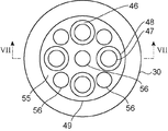
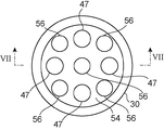
図7は、本発明に係る冷却装置の第2の実施の形態の立断面を示す図8および図9のVII-VII矢視立断面図である。図8は、図7のVIII-VIII矢視水平断面図である。図9は、図7のIX-IX矢視水平断面図である。
図7は、本発明に係る冷却装置の第2の実施の形態の立断面を示す図8および図9のVII-VII矢視立断面図である。図8は、図7のVIII-VIII矢視水平断面図である。図9は、図7のIX-IX矢視水平断面図である。
本実施の形態の冷却装置3は、4つの電磁ポンプ11を有している。また、4つの電磁ポンプ11に対応して、4組の内管47および外管48が設けられている。それぞれの電磁ポンプ11は、それぞれの内管47および外管48の間に形成された環状流路を流れる液体金属に推進力を与える。
また、この冷却装置3は、底板54、回収板55および回収管56を有している。底板54は、外容器30の軸に垂直な円形の平板であって、外容器30の底部近傍に設けられている。底板54の外縁は、外容器30の内面に接している。回収板55は、外容器30の軸に垂直な円形の平板であって、仕切筒49の端部に設けられている。回収板55の外縁は、仕切筒49の端部に接している。
内管47の端部は、底板54に固定されている。底板54には、内管47の内部と連通する貫通孔が形成されている。また、回収管56は、底板54と回収板55との間に延びている。底板54および回収板55には、回収管56の内部と連通する貫通孔が形成されている。外管48は、回収板55に固定されている。回収板55には、外管48の内部と連通する貫通孔が形成されている。
外管48の回収板55側の端部と内管47との間は、環状の取込口42となっている。この取込口42から外管48および内管47の外容器30の開口部に近い方の端部に向かって液体金属の往流路46が形成されている。外管48および内管47の外容器30の開口部に近い方の端部近傍には、それぞれ周方向の異なる位置に複数の吐出口41が形成されている。仕切筒49の内側であって、外管48の外側の領域は、液体金属の復流路45となっている。内管47の内部も復流路45となっている。
仕切筒49は、たとえば蓋15に固定され、外容器30の内部に吊り込まれている。また、内管47および外管48は、たとえば蓋15に固定され、仕切筒49の内側の空間に配置される。なお、本実施の形態では、第1の実施の形態における蒸気発生器底板50(図1参照)および蒸気発生器天板51(図1参照)は設けていない。
それぞれの外管48には、流量計24が取り付けられている。流量計24は、たとえば電磁ポンプ11の上流側に設けられている。流量計24は、内管47と外管48との間の環状の往流路46を流れる液体金属の流速を測定する。それぞれの電磁ポンプ11は、流量計24で測定された流速に基づいて駆動力が調整される。
冷却装置3に流入した液体金属は、まず、仕切筒49の外側の環状空間に設けられた蒸気発生器8に流れ込む。蒸気発生器8の内部では、仕切筒49と外容器30との間の環状空間を流れる液体金属と、その環状空間にらせん状に延びる伝熱管37を流れる水とが熱交換する。その結果、伝熱管37を流れる水は加熱され、液体金属は冷却される。
入口33から流入した水は、伝熱管37の内部を流れ、液体金属による加熱によって沸騰し、蒸気が発生する。発生した蒸気は、出口34から排出されて、発電タービンに送られる。
蒸気発生器8の内部で水と熱交換した液体金属は、仕切筒49の下端を通過して、底板54と回収板55との間の空間に流入する。底板54と回収板55との間の空間に流入した液体金属は、取込口42から外管48と内管47との間の環状の往流路46に流れ込む。外管48と内管47との間の往流路46を流れる液体金属は、電磁ポンプ11によって推進力を与えられる。電磁ポンプ11によって推進力を与えられた液体金属は、さらに往流路46を流れ、内管47および外管48に形成された吐出口41から吐出される。
吐出口41から吐出された液体金属は、内管47の内部および外管48の外部の復流路45を回収板55に向かって流れる。さらに液体金属は、回収板55に形成された貫通孔およびそれらの貫通孔に連通する回収管56を通過して、底板54と外容器30の底部との間の空間に回収される。底板54と外容器30の底部との間の空間に回収された液体金属は、排出口32を通過して、排出配管14に排出される。排出配管14に排出された液体金属は、中間熱交換器2に戻る。
本実施の形態の冷却装置3では、複数の電磁ポンプ11によって液体金属に電磁ポンプ11で推進力を与えて循環させている。このため、何らかの不具合により一部の電磁ポンプ11がトリップした場合であっても、残りの電磁ポンプ11によって液体金属を循環させることができる。その結果、原子炉の炉心を適切に冷却することができ、原子炉の安全性がより向上する。
[他の実施の形態]
上述の各実施の形態は単なる例示であり、本発明はこれらに限定されない。また、各実施の形態の特徴を組み合わせて実施することもできる。
上述の各実施の形態は単なる例示であり、本発明はこれらに限定されない。また、各実施の形態の特徴を組み合わせて実施することもできる。
1…原子炉容器、2…中間熱交換器、3…冷却装置、7…流入配管、8…蒸気発生器、11…電磁ポンプ、14…排出配管、15…蓋、24…流量計、30…外容器、31…流入口、32…排出口、33…入口、34…出口、35…水供給配管、36…蒸気配管、37…伝熱管、38…内コイル、39…外コイル、40…取込口、41…吐出口、42…取込口、45…復流路、46…往流路、47…内管、48…外管、49…仕切筒、50…蒸気発生器底板、51…蒸気発生器天板、52…貫通孔、53…貫通孔、54…底板、55…回収板、56…回収管、61…一次冷却系、62…二次冷却系
Claims (5)
- 液体金属を冷却媒体で冷却する冷却装置において、
開口部と前記液体金属の流入口および排出口と前記冷却媒体の入口および出口とが形成された外容器と、
前記開口部を閉じる蓋と、
前記外容器の内部を前記流入口と前記入口と前記出口とに面する第1空間と前記開口部と前記排出口とに面する第2空間とに仕切る仕切りと、
前記第1空間の内部で前記入口から前記出口に延びる伝熱管と、
前記第2空間を前記第1空間に連通して前記開口部に向かって延びる往路と前記往路の終端部から前記排出口まで延びる復路とに区切る構造体と、
前記第2空間に配置されて前記液体金属を前記往路から前記復路に向かって流す電磁ポンプと、
を有することを特徴とする冷却装置。 - 前記外容器は円筒状に形成され、前記仕切りは円筒状に形成されて前記外容器と同軸に配置され、前記伝熱管は前記仕切りの軸に沿ってらせん状に延びていることを特徴とする請求項1に記載の冷却装置。
- 前記構造体は環状の流路を形成する部分を含み、前記電磁ポンプは前記環状の流路を流れる前記液体金属に推進力を与えるものであることを特徴とする請求項1に記載の冷却装置。
- 前記電磁ポンプは複数であることを特徴とする請求項1ないし請求項3のいずれか1項に記載の冷却装置。
- 炉心を収めた原子炉容器と、
液体金属を前記炉心で発生した熱で加熱して前記炉心を冷却する冷却系と、
開口部と前記液体金属の流入口および排出口と水の入口および出口とが形成された外容器と、前記開口部を閉じる蓋と、前記外容器の内部を前記流入口と前記入口と前記出口とに面する第1空間と前記開口部と前記排出口とに面する第2空間とに仕切る仕切りと、前記第1空間の内部で前記入口から前記出口に延びる伝熱管と、前記第2空間を前記第1空間に連通して前記開口部に向かって延びる往路と前記往路の終端部から前記排出口まで延びる復路とに区切る構造体と、前記第2空間に配置されて前記液体金属を前記往路から前記復路に向かって流す電磁ポンプと、を備えて前記出口から蒸気を排出する冷却装置と、
を有することを特徴とする原子力蒸気供給システム。
Applications Claiming Priority (2)
| Application Number | Priority Date | Filing Date | Title |
|---|---|---|---|
| JP2010236745A JP2012088240A (ja) | 2010-10-21 | 2010-10-21 | 冷却装置および原子力蒸気供給システム |
| JP2010-236745 | 2010-10-21 |
Publications (1)
| Publication Number | Publication Date |
|---|---|
| WO2012053215A1 true WO2012053215A1 (ja) | 2012-04-26 |
Family
ID=45974944
Family Applications (1)
| Application Number | Title | Priority Date | Filing Date |
|---|---|---|---|
| PCT/JP2011/005878 Ceased WO2012053215A1 (ja) | 2010-10-21 | 2011-10-20 | 冷却装置および原子力蒸気供給システム |
Country Status (2)
| Country | Link |
|---|---|
| JP (1) | JP2012088240A (ja) |
| WO (1) | WO2012053215A1 (ja) |
Cited By (1)
| Publication number | Priority date | Publication date | Assignee | Title |
|---|---|---|---|---|
| US20250243852A1 (en) * | 2024-01-31 | 2025-07-31 | Ge-Hitachi Nuclear Energy Americas Llc | Electromagnetic pumps and methods of operating the same with improved cooling |
Families Citing this family (1)
| Publication number | Priority date | Publication date | Assignee | Title |
|---|---|---|---|---|
| JP2016101007A (ja) * | 2014-11-21 | 2016-05-30 | 株式会社東芝 | 電磁ポンプ及び流量計測システム |
Citations (3)
| Publication number | Priority date | Publication date | Assignee | Title |
|---|---|---|---|---|
| JPH0686532A (ja) * | 1992-08-31 | 1994-03-25 | Toshiba Corp | 電磁ポンプ |
| JPH0854101A (ja) * | 1994-08-11 | 1996-02-27 | Toshiba Corp | 蒸気発生器 |
| JPH1130686A (ja) * | 1997-07-10 | 1999-02-02 | Toshiba Corp | 液体金属冷却型原子炉の蒸気発生器および冷却システム |
-
2010
- 2010-10-21 JP JP2010236745A patent/JP2012088240A/ja not_active Withdrawn
-
2011
- 2011-10-20 WO PCT/JP2011/005878 patent/WO2012053215A1/ja not_active Ceased
Patent Citations (3)
| Publication number | Priority date | Publication date | Assignee | Title |
|---|---|---|---|---|
| JPH0686532A (ja) * | 1992-08-31 | 1994-03-25 | Toshiba Corp | 電磁ポンプ |
| JPH0854101A (ja) * | 1994-08-11 | 1996-02-27 | Toshiba Corp | 蒸気発生器 |
| JPH1130686A (ja) * | 1997-07-10 | 1999-02-02 | Toshiba Corp | 液体金属冷却型原子炉の蒸気発生器および冷却システム |
Cited By (1)
| Publication number | Priority date | Publication date | Assignee | Title |
|---|---|---|---|---|
| US20250243852A1 (en) * | 2024-01-31 | 2025-07-31 | Ge-Hitachi Nuclear Energy Americas Llc | Electromagnetic pumps and methods of operating the same with improved cooling |
Also Published As
| Publication number | Publication date |
|---|---|
| JP2012088240A (ja) | 2012-05-10 |
Similar Documents
| Publication | Publication Date | Title |
|---|---|---|
| US10811152B2 (en) | Heat exchanger and nuclear power plant comprising same | |
| CN206258002U (zh) | 热交换器 | |
| KR20040081958A (ko) | 액체금속로용 증기발생기와 이의 전열방법 | |
| WO2020202806A1 (ja) | 原子力発電システム及び原子炉ユニット | |
| CN103380347A (zh) | 废气冷却器 | |
| JP5278020B2 (ja) | Egrガス冷却装置 | |
| CN202309336U (zh) | 用于电机的壳体 | |
| US20040226694A1 (en) | Heat exchanger with removable core | |
| JP2012088240A (ja) | 冷却装置および原子力蒸気供給システム | |
| CN102013751A (zh) | 一种带螺旋形翅片管的水冷机座 | |
| CN108981427B (zh) | 一种列管式热交换器 | |
| JP2017203420A (ja) | 排気熱回収装置 | |
| KR101831220B1 (ko) | 플래시 박스 및 그것을 구비하는 복수기 | |
| JP2006162339A (ja) | 熱交換器及び原子炉 | |
| JP3137708U (ja) | 水冷式ヒートシンクモジュール | |
| CN202813324U (zh) | 一种核动力装置用热管式蒸汽发生器 | |
| KR20170028334A (ko) | 일체형 원자로 및 이를 구비하는 원전 | |
| EP4206746A1 (en) | Heat dissipation structure and inspection apparatus | |
| JP2017166403A (ja) | 排気熱回収装置 | |
| JP2014194319A (ja) | 熱交換器 | |
| KR20150098451A (ko) | 쉘 앤드 튜브 타입 열교환기 | |
| JP2017002811A (ja) | 排熱回収器 | |
| CN102592690A (zh) | 一种浮头式铅铋换热装置及换热方法 | |
| JP2014105944A (ja) | 熱交換器 | |
| CN110176824A (zh) | 一种电动客车的驱动电机液冷端盖 |
Legal Events
| Date | Code | Title | Description |
|---|---|---|---|
| 121 | Ep: the epo has been informed by wipo that ep was designated in this application |
Ref document number: 11834061 Country of ref document: EP Kind code of ref document: A1 |
|
| NENP | Non-entry into the national phase |
Ref country code: DE |
|
| 122 | Ep: pct application non-entry in european phase |
Ref document number: 11834061 Country of ref document: EP Kind code of ref document: A1 |