WO2012050149A1 - X線ct装置及び画像再構成方法 - Google Patents
X線ct装置及び画像再構成方法 Download PDFInfo
- Publication number
- WO2012050149A1 WO2012050149A1 PCT/JP2011/073473 JP2011073473W WO2012050149A1 WO 2012050149 A1 WO2012050149 A1 WO 2012050149A1 JP 2011073473 W JP2011073473 W JP 2011073473W WO 2012050149 A1 WO2012050149 A1 WO 2012050149A1
- Authority
- WO
- WIPO (PCT)
- Prior art keywords
- projection data
- ray
- matrix
- successive approximation
- extended
- Prior art date
- Legal status (The legal status is an assumption and is not a legal conclusion. Google has not performed a legal analysis and makes no representation as to the accuracy of the status listed.)
- Ceased
Links
Images






Classifications
-
- G—PHYSICS
- G06—COMPUTING OR CALCULATING; COUNTING
- G06T—IMAGE DATA PROCESSING OR GENERATION, IN GENERAL
- G06T12/00—Tomographic reconstruction from projections
- G06T12/20—Inverse problem, i.e. transformations from projection space into object space
-
- A—HUMAN NECESSITIES
- A61—MEDICAL OR VETERINARY SCIENCE; HYGIENE
- A61B—DIAGNOSIS; SURGERY; IDENTIFICATION
- A61B6/00—Apparatus or devices for radiation diagnosis; Apparatus or devices for radiation diagnosis combined with radiation therapy equipment
- A61B6/02—Arrangements for diagnosis sequentially in different planes; Stereoscopic radiation diagnosis
- A61B6/03—Computed tomography [CT]
- A61B6/032—Transmission computed tomography [CT]
-
- A—HUMAN NECESSITIES
- A61—MEDICAL OR VETERINARY SCIENCE; HYGIENE
- A61B—DIAGNOSIS; SURGERY; IDENTIFICATION
- A61B6/00—Apparatus or devices for radiation diagnosis; Apparatus or devices for radiation diagnosis combined with radiation therapy equipment
- A61B6/52—Devices using data or image processing specially adapted for radiation diagnosis
- A61B6/5205—Devices using data or image processing specially adapted for radiation diagnosis involving processing of raw data to produce diagnostic data
-
- A—HUMAN NECESSITIES
- A61—MEDICAL OR VETERINARY SCIENCE; HYGIENE
- A61B—DIAGNOSIS; SURGERY; IDENTIFICATION
- A61B6/00—Apparatus or devices for radiation diagnosis; Apparatus or devices for radiation diagnosis combined with radiation therapy equipment
- A61B6/52—Devices using data or image processing specially adapted for radiation diagnosis
- A61B6/5258—Devices using data or image processing specially adapted for radiation diagnosis involving detection or reduction of artifacts or noise
- A61B6/5264—Devices using data or image processing specially adapted for radiation diagnosis involving detection or reduction of artifacts or noise due to motion
-
- G—PHYSICS
- G06—COMPUTING OR CALCULATING; COUNTING
- G06T—IMAGE DATA PROCESSING OR GENERATION, IN GENERAL
- G06T2211/00—Image generation
- G06T2211/40—Computed tomography
- G06T2211/424—Iterative
Definitions
- the present invention relates to an X-ray CT apparatus or the like for reconstructing an image by a successive approximation method.
- X-ray CT equipment irradiates a subject with fan beam (fan beam) or cone beam (cone or pyramid beam) X-rays, measures the X-rays transmitted through the subject with an X-ray detector, This is an apparatus for obtaining a tomographic image of a subject by reconstructing measurement data from multiple directions.
- the image reconstruction method in the X-ray CT apparatus is roughly divided into an analysis method and a successive approximation method.
- the analysis method is a method of solving a problem analytically based on the projected cutting plane theorem.
- the successive approximation method is a method of mathematically modeling an observation system that leads to acquisition of projection data and estimating the best image by an iterative method based on the mathematical model.
- the advantage of the analysis method is that the reconstructed image can be obtained directly from the actual projection data, so that the amount of calculation is overwhelmingly small.
- the advantage of the successive approximation method is that the physical process leading to the acquisition of projection data and the statistical fluctuations included in the actual projection data can be considered as mathematical models and statistical models, respectively. Beam artifacts) and quantum noise on the image can be reduced.
- the Feldkamp method which is an analysis method, or a method obtained by improving the Feldkamp method is mainly used because of the small amount of calculation.
- the practical use of the successive approximation method has begun to be studied.
- the successive approximation method is a method in which an evaluation index of an image is set in advance and the image is sequentially updated so that an evaluation value obtained by quantifying the evaluation index takes a maximum value or a minimum value.
- the evaluation index the contradiction between the forward projection data obtained by converting the image into projection data during the update process and the actual projection data, probabilistic likelihood, etc. are used, and the function for calculating the evaluation value is called the evaluation function .
- Non-Patent Document 1 proposes a successive approximation method using a penalized weighted square error function as an evaluation function. As a method proposed so far, as proposed in Non-Patent Document 1, it is common to operate matrices that are transposed in the forward projection process and the backprojection process.
- Non-Patent Document 2 proposes a method of performing sequential updating by applying view direction weights to back projection processing.
- view direction weighted back projection process the back projection process using the view direction weight.
- the view direction weighted backprojection process itself is a technique proposed in Non-Patent Document 3 and used in the analysis method.
- the view direction weighted backprojection processing has the following advantages. (1) The redundancy of projection data can be eliminated. (2) Time resolution can be improved.
- the update formula for performing the sequential update includes a relaxation coefficient related to the convergence speed and stability of the successive approximation method. In order for the successive approximation method to converge stably, it is necessary to set the relaxation coefficient within a specific range.
- Non-patent document 2 describes that the relaxation coefficient is determined empirically.
- Non-Patent Document 4 proposes a method of calculating a relaxation coefficient using a power method.
- the power method is an iterative method for obtaining the maximum eigenvalue of an arbitrary matrix.
- Patent Document 1 describes a method of performing back projection processing after generating actual column data and virtual channel data by expanding actual projection data in the analysis method. If the method of Patent Document 1 can be applied to the successive approximation method, the restriction on the region can be relaxed.
- Non-Patent Document 2 As in the method of Non-Patent Document 2, by using the view direction weighted back projection processing by the successive approximation method, it is possible to reduce the deterioration of the image quality due to the movement of the subject. However, the method of Non-Patent Document 2 has a problem caused by the operator empirically determining the relaxation coefficient.
- the sufficient condition of the relaxation coefficient for convergence of the successive approximation method changes depending on the bed feeding speed and the shooting FOV (Field Of View) as shooting conditions. It is very cumbersome and time consuming for the operator to determine the relaxation coefficient empirically according to these many imaging conditions.
- the relaxation coefficient when the relaxation coefficient is set to a small value, the convergence condition of the successive approximation process is satisfied regardless of the shooting conditions due to the nature of the update matrix. However, if the relaxation coefficient is set to a too small value, the convergence of the successive approximation process is delayed, and the image quality of the reconstructed image is also deteriorated.
- the relaxation coefficient is determined using the power method
- the relaxation coefficient is automatically calculated according to the shooting conditions, so that the successive approximation method itself converges stably.
- the method of Non-Patent Document 4 requires the sequential calculation of a large-scale matrix operation, and the calculation time Will increase.
- Non-Patent Document 2 and Non-Patent Document 4 it is necessary to set an optimal value for the relaxation coefficient. That is, if the relaxation coefficient is not set to an optimum value, there remains a problem that the calculation time increases.
- the present invention has been made in view of the above-described problems, and a first object thereof is to provide an X-ray CT apparatus and the like that reconstructs an image by a successive approximation method that can be stably converged and executed at high speed. That is.
- the second object is to provide an X-ray CT apparatus and the like that can suppress image quality degradation when the successive approximation method is applied to data with body movement.
- a third object is to provide an X-ray CT apparatus or the like that can suppress image quality degradation when the successive approximation method is applied under imaging conditions in which data loss occurs during spiral scanning or axial scanning with a high bed moving speed. It is.
- the first invention is an X-ray CT apparatus that reconstructs a tomographic image of a subject by a successive approximation method in which matrices that are not transposed are applied to each other in forward projection processing and backprojection processing.
- the actual projection data using an imaging unit that acquires actual projection data of the subject based on the imaging conditions, and an update formula of the successive approximation method that includes the imaging conditions and a relaxation coefficient that determines convergence of calculation.
- an arithmetic unit that reconstructs the tomographic image by performing successive approximation on the X-ray CT apparatus, wherein the relaxation coefficient is analytically calculated based on the imaging conditions .
- a second invention is an image reconstruction method for reconstructing a tomographic image of a subject by a successive approximation method in which matrices that are not transposed are applied to each other in forward projection processing and backprojection processing.
- an X-ray CT apparatus that reconstructs an image by a successive approximation method that converges stably and can be executed at high speed.
- an X-ray CT apparatus or the like that can suppress image quality degradation when the successive approximation method is applied to data with body movement.
- an X-ray CT apparatus and the like that can suppress image quality deterioration when the successive approximation method is applied under imaging conditions in which data loss occurs during spiral scanning or axial scanning with a high bed moving speed.
- the X-ray CT apparatus 1 includes a scanner 2 (imaging unit) on which an X-ray tube 11 and a detector 12 are mounted, a bed 4 on which a subject 10 is placed, and data obtained from the detector 12. And an input device 6 such as a mouse, a trackball, a keyboard, and a touch panel, a display device 7 that displays a reconstructed image, and the like.
- a scanner 2 imaging unit
- an input device 6 such as a mouse, a trackball, a keyboard, and a touch panel
- a display device 7 that displays a reconstructed image, and the like.
- the operator inputs shooting conditions and reconstruction parameters via the input device 6.
- the imaging conditions are, for example, a bed feeding speed, a tube current, a tube voltage, and a slice position.
- the reconstruction parameter is, for example, a region of interest, a reconstructed image size, a backprojection phase width, a reconstruction filter function, or the like.
- the X-ray CT apparatus 1 is roughly composed of a scanner 2, an operation unit 3, and a bed 4.
- the scanner 2 includes an X-ray tube 11 (X-ray generator), a detector 12, a collimator 13, a drive device 14, a central controller 15, an X-ray controller 16, a high voltage generator 17, a scanner controller 18, and a bed control.
- the apparatus 19 includes a bed movement measuring apparatus 20, a collimator control apparatus 21, a preamplifier 22, an A / D converter 23, and the like.
- the central controller 15 inputs imaging conditions and reconstruction parameters from the input device 6 in the operation unit 3, and sends control signals necessary for imaging to the collimator controller 21, the X-ray controller 16, the scanner controller 18, and the bed control. Transmit to device 19.
- the collimator control device 21 controls the position of the collimator 13 based on the control signal.
- the X-ray control device 16 controls the high voltage generator 17 based on the control signal.
- the high voltage generator 17 applies a tube voltage and a tube current to the X-ray tube 11 (X-ray generator).
- X-ray generator In the X-ray tube 11, electrons with energy corresponding to the applied tube voltage are emitted from the cathode, and the emitted electrons collide with the target (anode), whereby X-rays with energy corresponding to the electron energy are Is irradiated.
- the scanner control device 18 controls the drive device 14 based on the control signal.
- the driving device 14 circulates around the subject 10 around a gantry portion on which the X-ray tube 11, the detector 12, the preamplifier 22, and the like are mounted.
- the bed control device 19 controls the bed 4 based on the control signal.
- the X-ray irradiated from the X-ray tube 11 is limited in the irradiation region by the collimator 13, is absorbed (attenuated) according to the X-ray attenuation coefficient in each tissue in the subject 10, passes through the subject 10, It is detected by a detector 12 arranged at a position facing the tube 11.
- the detector 12 includes a plurality of detection elements arranged in a two-dimensional direction (a channel direction and a column direction perpendicular to the channel direction). X-rays received by each detection element are converted into projection data (hereinafter referred to as “actual projection data”).
- the X-rays detected by the detector 12 are converted into current, amplified by the preamplifier 22, converted into digital data by the A / D converter 23, LOG converted, calibrated, and used as actual projection data. Input to the arithmetic unit 5.
- the computing device 5 includes a reconstruction computing device 31, an image processing device 32, and the like.
- the input / output device 9 includes an input device 6, a display device 7, a storage device 8 (storage unit), and the like.
- the reconstruction calculation device 31 performs an image reconstruction process using the actual projection data, and generates a reconstructed image.
- the reconstruction calculation device 31 generates filter correction projection data by superimposing a reconstruction filter on the actual projection data of each view, and weights the filter correction projection data in the view direction (hereinafter referred to as “view direction weight”). .) Is weighted and the back projection process is performed to form a non-destructive tomographic image as a distribution map of the X-ray attenuation coefficient inside the subject 10.
- the reconstruction calculation device 31 stores the generated reconstruction image in the storage device 8. In addition, the reconstruction calculation device 31 displays a reconstruction image as a CT image on the display device 7. Alternatively, the image processing device 32 performs image processing on the reconstructed image stored in the storage device 8, and displays the reconstructed image subjected to the image processing on the display device 7 as a CT image.
- the X-ray CT apparatus 1 is a multi-slice CT that uses a detector 12 in which detector elements are arranged in a two-dimensional direction, and a single that uses a detector 12 in which detector elements are arranged in one row, that is, in a one-dimensional direction (channel direction only). Broadly divided into slice CT.
- multi-slice CT an X-ray beam spreading in a cone shape or a pyramid shape is irradiated from an X-ray tube 11 as an X-ray source in accordance with the detector 12.
- an X-ray beam spreading in a fan shape is emitted from the X-ray tube 11.
- X-ray irradiation is performed while the gantry section circulates around the subject 10 placed on the bed 4 (however, scanogram imaging is excluded). ).
- imaging in which the bed 4 is fixed during imaging and the X-ray tube 11 circulates around the subject 10 in a circular orbit is called an axial scan or the like.
- imaging in which the bed 4 moves and the X-ray tube 11 circulates around the subject 10 in a spiral trajectory is called a spiral scan.
- the bed controller 20 keeps the bed 4 stationary in the case of the axial scan. Further, in the case of the helical scan, the bed control device 20 translates the bed 4 in the body axis direction in accordance with the bed feeding speed as an imaging condition input via the input device 6.
- the X-ray CT apparatus 1 is, for example, a multi-slice CT. Further, the scan method of the X-ray CT apparatus 1 is, for example, a rotate-rotate method (third generation).
- Non-Patent Document 1 a successive approximation method using a penalized weighted square error function as an evaluation function.
- x (k) is a vector (image vector) representing an image in the k-th sequential update
- y is a vector representing actual projection data.
- A is a matrix that associates an image with projection data, and is referred to as a system matrix because it represents the characteristics of the imaging system via the mathematical model described above.
- a T represents a transposed matrix of A.
- Ax (k) corresponds to processing (forward projection processing) for converting the image vector x (k) into a projection data vector.
- a T ( ⁇ ) corresponds to processing (back projection processing) for converting the projection data vector in parentheses into an image vector.
- D is a diagonal matrix having a weighting factor weighted to the difference value between the actual projection data and the forward projection data as a diagonal component.
- a value corresponding to the number of detected photons is used as the weighting factor.
- ⁇ is an optional parameter that adjusts the strength of the penalty term.
- the penalty term has a role of suppressing the high-frequency enhancement effect of the image by applying the successive approximation method.
- S is a matrix having the inverse of each element of the vector s represented by the following equation as a diagonal component.
- c is a vector having the same number of elements as the image vector and having 1 as a value for all elements.
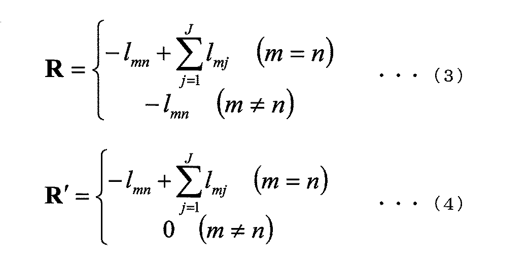
- R in Equation (1) and R ′ in Equation (2) are linear operators of the first and second derivatives of the penalty term, and both are conversion matrices from image vectors to image vectors.
- Non-Patent Document 2 for example.
- the view direction weighted back projection process itself is proposed in Non-Patent Document 3.
- Non-Patent Document 2 is expressed by the following equation.
- ⁇ is a relaxation coefficient related to the convergence speed and stability of the successive approximation method.
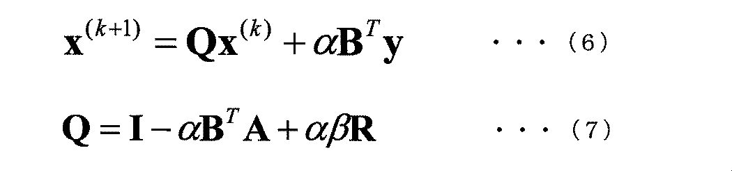
- equation (5) is modified as follows.
- the matrix Q in the equation (7) is called an update matrix.
- the update matrix is a matrix that determines an image update amount and an update direction per one-time sequential update process based on the update formula.
- I represents a unit matrix.
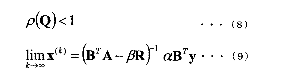
- the power eigenmethod is used to calculate the maximum eigenvalue of the update matrix, thereby calculating the spectrum radius ⁇ (Q) shown in Equation (8), and the relaxation coefficient. ⁇ is set.
- the power method is not a method for solving the problem analytically, and it is necessary to sequentially calculate a large-scale matrix operation, which increases the calculation time.
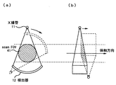
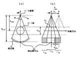
- FIG. 4 (a) shows the arrangement of the detector 12 and the X-ray tube 11 in the imaging section. Moreover, scanFOV41 in the imaging
- the scanFOV41 is a region where an image is formed based on the projection cut surface theorem.
- the scanFOV41 in the photographing section is almost circular.
- FIG. 4 (b) shows the arrangement of the detector 12 and the X-ray tube 11 in the body axis direction. Moreover, scanFOV41 in the body axis direction is shown.
- the scanFOV 41 in the body axis direction is a polygon such as a triangle, a quadrangle, or a pentagon, although it varies depending on the bed moving speed.
- Fig. 5 shows the difference in scanFOV41 in the body axis direction due to the difference in bed movement speed. Comparing FIG. 5 (a) and FIG. 5 (b), it can be seen that the faster the bed moving speed, the narrower the width of the scanFOV 41 in the body axis direction. If the width of scanFOV41 in the body axis direction is narrower than the specified value, it means that the 180-degree view necessary to reconstruct a tomographic image has not been acquired, which limits the area where images can be created. Means that
- the area in which an image can be created is also limited in the peripheral visual field in the body axis direction during axial scanning.
- a relaxation coefficient value for stably converging the successive approximation method is analytically calculated. Then, an image reconstruction process is performed by a successive approximation method that performs a view direction weighted backprojection process.
- the view direction weighted backprojection process uses the scan characteristics of the X-ray CT apparatus 1 shown below.
- FIG. 6A shows the transmission path of the target view and the transmission path of the opposite phase view in the channel direction.
- FIG. 6B shows the transmission path of the target view and the transmission path of the opposite phase view in the column direction.
- data having such a relationship will be referred to as actual projection data of opposite phase.
- the X-ray CT apparatus 1 collects data while rotating the X-ray tube 11 and the detector 12, an imaging time difference occurs in the view direction of the actual projection data. If the bed moving speed during imaging is constant, the imaging time difference is proportional to the distance between the body axis direction position of the X-ray tube 11 and the body axis direction position of the image.
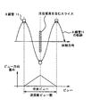
- FIG. 7 is a conceptual diagram of view direction weights.
- the arithmetic device 5 of the X-ray CT apparatus 1 has, as the view direction weight, according to the distance between the body axis direction position of the slice including the pixel of interest and the body axis direction position of the X-ray tube 11, A weight is added so as to add 1 between the actual projection data in the opposite phase.
- the arithmetic unit 5 of the X-ray CT apparatus 1 calculates the view direction weight by a predetermined number of views on both sides centering on the view in the body axis direction position of the X-ray tube 11 that is closest to the target pixel in the body axis direction. 0 weights except for the view.
- a view to which a weight other than 0 is attached is referred to as a backprojection view
- the number of backprojection views is referred to as a backprojection view number.
- the optimal number of backprojection views is determined by the helical pitch (value determined by the bed feeding speed and the gantry rotation speed as imaging conditions) and the length of the detector 12 in the row direction.
- the view direction weight By defining the view direction weight in this way, the time resolution can be improved as compared with the case where the view direction weight is not used. This is because the time phases of a plurality of views that contribute to the image reconstruction process are substantially matched by the view direction weight.
- the definition of view direction weights may use a common backprojection view number for all pixels and determine a central view for each slice. Further, the definition of the view direction weight may determine the central view for each pixel as disclosed in “JP 2004-199163”. Further, the definition of the view direction weight may determine the number of backprojection views in each pixel.
- the view direction weight is the actual projection data Since it is set for each element of the vector and the image vector, it is defined as w ij .
- the elements of the system matrix A and a ij, the elements of the system matrix B multiplied by the view direction weight putting and b ij, b ij can be expressed as the following equation .
- the back projection matrix representing the view direction weighted back projection processing is B T.
- the system matrix A is a matrix that associates an image with projection data.
- the computing device 5 of the X-ray CT apparatus 1 calculates each element a ij based on the apparatus specifications of the X-ray CT apparatus 1 and the imaging conditions input from the input device 6.
- a calculation method of the system matrix A for example, the Joseph method proposed in “Joseph, PM (1982). An Improved Algorithm for Reprojecting Rays Through Pixel Images. IEEE Transactions on Medical Imaging MI-1, 192-196.” Is mentioned.
- Examples of the apparatus specifications of the X-ray CT apparatus 1 used for the calculation of the system matrix A include the following. -Number of elements in the column direction of the detector 12-Number of elements in the channel direction of the detector 12-Size of one element in the column direction of the detector 12-Size of one element in the channel direction of the detector 12-Between the X-ray tube 11 and the rotation center Distance d sod The distance d sid between the X-ray tube 11 and the center of the detector 12 (detector center)
- imaging conditions used for the calculation of the system matrix A include the following.
- Beam pitch value obtained by dividing the bed feeding speed by the row direction detector size at the rotation center: “value corresponding to high speed” or “value corresponding to low speed”.
- -Shooting rotation speed-Shooting start angle-Rotation speed-Number of shooting views per rotation-Shooting method “Axial scan” or "Helix scan”.
- -Number of pixels (in the cross section): Number of pixels in the horizontal direction x Number of pixels in the vertical direction-Number of image slices-Pixel size (in the cross section) -Image slice thickness and image center position (within the cross section): “Matches the rotation center”. -Image slicing direction center position: “Same as the number of rotations of shooting 2.5.”
- the system matrix A is different when the beam pitch, which is one of the imaging conditions, is “a value corresponding to high speed” and “a value corresponding to low speed”.
- the relaxation coefficient ⁇ at which the successive approximation method converges stably is also different.
- the spectrum radius of the update matrix is calculated by the power method, but there is a problem that the calculation time and the amount of memory used for the calculation are large. Therefore, the X-ray CT apparatus 1 according to the present invention calculates the operator norm of the update matrix instead of calculating the spectrum radius of the update matrix.
- the matrix operator norm has the following properties.
- equation (8) can be replaced as follows: Obviously, when the operator norm of the update matrix is smaller than 1 (when the equation (13) is satisfied), the spectral radius of the update matrix is smaller than 1 (the equation (8) is satisfied).
- Non-Patent Document 3 an example of introducing a view direction weighted back projection process and a relaxation coefficient to the method proposed in Non-Patent Document 3 will be given.
- the present invention is not limited to this example, and can be applied to any successive approximation method including an update matrix in which the spectrum radius can be adjusted by a relaxation coefficient.
- S is a matrix having the inverse of each element of the vector s represented by the following equation as a diagonal component.
- the matrix norm of the matrix on the left side of equation (17) can have any number of orders.
- the arithmetic unit 5 of the X-ray CT apparatus 1 adds the elements of the matrix I- ⁇ (SB T DA + ⁇ SR) in the column direction, the maximum value in the row direction, operator norm
- the arithmetic unit 5 of the X-ray CT apparatus 1 analytically calculates the relaxation coefficient ⁇ based on the imaging conditions.
- the X-ray CT apparatus 1 can determine the relaxation coefficient ⁇ at high speed and easily compared to the iterative solution of the eigenvalue problem represented by the power method.
- the relaxation coefficient ⁇ is determined based on the shooting conditions, the stability of the algorithm can be ensured as compared with the case where the relaxation coefficient ⁇ is determined empirically.
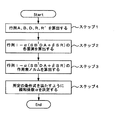
- the scanner 2 acquires the actual projection data of the subject 10 based on the imaging conditions, and the operator instructs the image reconstruction via the input device 6, the arithmetic device 5 of the X-ray CT apparatus 1 Based on the imaging conditions input from 6, matrixes A, B, D, R, and R ′ in equation (17) are calculated (step 1).
- the arithmetic unit 5 calculates each element of the matrix I ⁇ (SB T DA + ⁇ SR) (step 2).
- the arithmetic unit 5 calculates the operator norm
- the arithmetic unit 5 of the X-ray CT apparatus 1 analytically calculates the relaxation coefficient ⁇ based on the imaging conditions.
- the arithmetic unit 5 of the X-ray CT apparatus 1 determines the relaxation coefficient ⁇ , it re-creates the tomographic image by performing successive approximation on the actual projection data using the update formula of the successive approximation method including the imaging conditions and the relaxation coefficient ⁇ .
- the successive approximation method in the first embodiment applies matrices that are not transposed in the forward projection process and the backprojection process.
- the update formula of the successive approximation method in the first embodiment is the formula (14).
- the relaxation coefficient is calculated so as to satisfy Expression (17) defined based on the operator norm of the update matrix Q shown in Expression (16).
- Expression (17) defined based on the operator norm of the update matrix Q shown in Expression (16).
- (17) is an expression indicating that the operator norm of the update matrix Q is smaller than 1.
- the arithmetic device 5 of the X-ray CT apparatus 1 calculates the value of the relaxation coefficient ⁇ applied to the equation (14) as the maximum value satisfying the conditional equation of the equation (17). That is, it is desirable for the arithmetic unit 5 to set as large a value as possible within the range that satisfies the conditional expression (17) as the value of the relaxation coefficient ⁇ applied to the expression (14).
- the successive approximation method in the first embodiment performs back projection processing using view direction weights.
- Arithmetic unit 5 calculates view direction weights with a weight of 0 except for a predetermined number of views on both sides around the view of the X-ray tube position closest to the target pixel in the body axis direction.
- a back projection matrix B T that acts as a back projection process is calculated using the weight, and the successive approximation is performed on the actual projection data using the update formula of the formula (14) to which the back projection matrix B T is applied, and the subject 10 Reconstruct a tomographic image.
- the arithmetic device 5 of the X-ray CT apparatus 1 calculates the relaxation coefficient ⁇ based on the imaging conditions, and uses the relaxation coefficient ⁇ calculated by itself to perform the actual projection. It was assumed that successive approximation to the data was performed.
- the device that performs the calculation process of the relaxation coefficient ⁇ is not limited to the arithmetic device 5.
- the arithmetic unit 5 of the X-ray CT apparatus 1 or other computer has a relaxation coefficient ⁇ shown in FIG. 8 for each of various imaging conditions (for example, imaging conditions used for the calculation of the system matrix A described above).
- the calculation process is executed, and the calculation result is stored in the storage device 8 of the X-ray CT apparatus 1. That is, the storage device 8 stores the relaxation coefficient ⁇ for each photographing condition.
- the arithmetic device 5 of the X-ray CT apparatus 1 uses the imaging condition input from the input device 6 as a search key, and the setting value of the relaxation coefficient ⁇ stored in the storage device 8 It is good also as what performs successive approximation with respect to real projection data using the setting value of the relaxation coefficient (alpha) acquired as a search result.
- the image reconstruction process by the successive approximation method that performs the data expansion back projection process is executed using the relaxation coefficient ⁇ that is analytically calculated by the first embodiment.
- Such an image reconstruction process is effective when it is necessary to image a long range in the body axis direction of the subject 10 within a predetermined time. For example, it is effective in cases such as emergency medicine where priority is given to shortening the shooting time over image quality. However, according to the present invention, it is possible to reduce the photographing time and to maintain the image quality at a certain level.
- the projection data is expanded in the channel direction and the column direction, and the scanFOV 41 is expanded using virtual projection data (hereinafter referred to as “expansion projection data”). Is the purpose.
- extended scanFOV the scanFOV41 that is expanded by the application of the data expansion type back projection process is referred to as “extended scanFOV”.
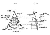
- Fig. 9 (a) shows expansion in the channel direction.
- the expansion channels 42a and 42b are projection data expanded in the channel direction.
- the channel direction expansion scanFOV43 is obtained by expanding the scanFOV41 by applying the data expansion back projection process using the expansion channels 42a and 42b.
- Fig. 9 (b) shows expansion in the column direction.
- the extended column 44 is projection data extended in the column direction.
- the column direction extended scanFOV 45 is obtained by extending the scanFOV 41 by using the extended column 44 and applying the data extended back projection process.
- the arithmetic device 5 of the X-ray CT apparatus 1 performs a process for calculating the number of extended columns and the number of extended channels based on the imaging conditions input from the input device 6 (step 11).
- the distance between the X-ray tube 11 and the rotation center is d sod .
- the distance between the X-ray tube 11 and the center of the detector 12 is d sid .
- FOM the FOM size is the size of the (Field Of Measurement) 51 and d phi.
- the FOM size d phi as shown in FIG. 12, among the vertices of the reconstructed FOV53 (image region to be created) is twice the distance between the rotation center and the farthest vertex 54 from the center of rotation.
- d dtc be the aperture width of the detection element in the body axis direction
- r re be the number of columns of the detection element
- r im be the number of columns to be expanded.
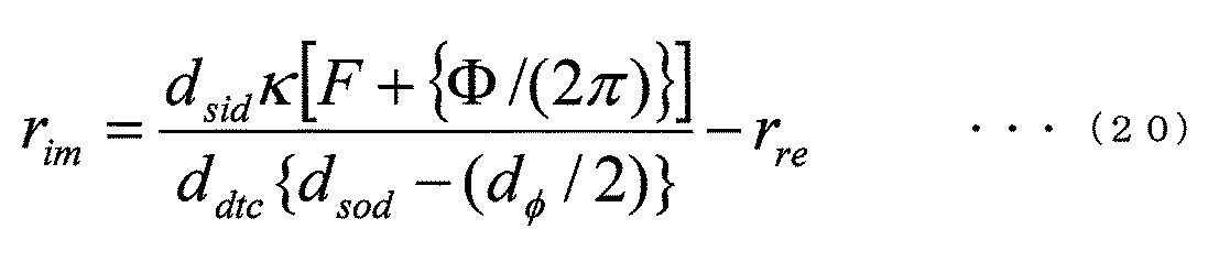
- a straight line connecting the X-ray tube 11 and the detector center 52 is defined as the q axis. Since the length of one row of detector elements is constant, by calculating r im, expansion columns is obtained.
- X-ray tube side plane a plane closer to the X-ray tube 11 (hereinafter referred to as “X-ray tube side plane”) out of two planes orthogonal to the q axis and in contact with the FOM 51.
- d s the length of the X-ray tube side plane and the X-ray beam intersecting in the body axis direction.
- F is the backprojection phase width, and in this embodiment, is a parameter for adjusting the trade-off between image quality degradation caused by estimation error of extended projection data and image quality degradation caused by loss of actual projection data. .
- r im is calculated according to the following equation.
- the arithmetic device 5 of the X-ray CT apparatus 1 calculates the number of columns r im to be expanded by the equation (20).
- the arithmetic unit 5 may expand the channel so as to include the extended scanFOV43 in the imaging section, and can easily calculate the number of extended channels.
- the arithmetic device 5 executes a process of creating extended projection data based on the number of extended columns and the number of extended channels calculated in step 11 (step 12).
- extended projection data in the column direction is estimated by extrapolation from difference data between forward projection data and actual projection data.
- extended projection data in the column direction is estimated by zero-order extrapolation using data that is located on the outermost side in the column direction among the data obtained as actual projection data.
- the projection value ⁇ of the extended projection data is It is expressed as the following formula.
- the computing device 5 of the X-ray CT apparatus 1 calculates the projection value ⁇ of the extended projection data by the equation (21).
- the arithmetic device 5 executes the back projection process by combining the actual projection data of the subject 10 acquired by the scanner 2 and the extended projection data created in Step 12 (Step 13).
- the present invention can also be applied to the axial scan.
- the channel direction and the column direction are expanded, only one of the channel direction and the column direction may be expanded.
- back projection processing is performed by using extended projection data obtained by extending real projection data in the channel direction and / or column direction.
- the arithmetic device 5 of the X-ray CT apparatus 1 analytically calculates the relaxation coefficient ⁇ based on the imaging conditions input by the input device 6 as in the first embodiment. Then, the arithmetic device 5 calculates a conversion matrix P from the actual projection data to the extended projection data based on the imaging conditions input by the input device 6, and combines the actual projection data and the extended projection data using the conversion matrix P.
- the successive approximation method by combining the first embodiment and the second embodiment uses the extended projection data obtained by extending the actual projection data in the channel direction and / or the column direction, and the view direction weight. By using this, back projection processing is performed.
- the arithmetic device 5 of the X-ray CT apparatus 1 analytically calculates the relaxation coefficient ⁇ based on the imaging conditions input by the input device 6 as in the first embodiment.
- the arithmetic device 5 calculates a conversion matrix P from the actual projection data to the extended projection data based on the imaging conditions input by the input device 6. Further, the computing device 5 calculates a view direction weight that gives a weight of 0 except for a predetermined number of views on both sides around the view of the X-ray tube position with the closest distance in the body axis direction to the target pixel, A back projection matrix B T to be operated as back projection processing is calculated using the view direction weight.
- the arithmetic unit 5 calculates an extended backprojection matrix that acts as a backprojection process combining the actual projection data and the extended projection data using the transformation matrix P and the view direction weight, and this extended backprojection matrix is applied.
- the tomographic image is reconstructed by performing successive approximation on the actual projection data and the extended projection data using the updating formula (14).
Landscapes
- General Physics & Mathematics (AREA)
- Engineering & Computer Science (AREA)
- Theoretical Computer Science (AREA)
- Physics & Mathematics (AREA)
- Apparatus For Radiation Diagnosis (AREA)
- Health & Medical Sciences (AREA)
- Mathematical Analysis (AREA)
- Radiology & Medical Imaging (AREA)
- Pure & Applied Mathematics (AREA)
- Mathematical Optimization (AREA)
- Algebra (AREA)
- Nuclear Medicine, Radiotherapy & Molecular Imaging (AREA)
- Pulmonology (AREA)
- Mathematical Physics (AREA)
- Life Sciences & Earth Sciences (AREA)
- Chemical & Material Sciences (AREA)
- Analytical Chemistry (AREA)
- Biochemistry (AREA)
- General Health & Medical Sciences (AREA)
- Immunology (AREA)
- Pathology (AREA)
Abstract
Description
(1)投影データの冗長性を排除できる。
(2)時間分解能を向上できる。
寝台制御装置19は、制御信号に基づいて寝台4を制御する。
)。



この問題については、図4、図5を参照しながら説明する。
第1の実施の形態では、画像再構成処理を実行する前に、逐次近似法を安定に収束させるための緩和係数の値を解析的に算出する。そして、ビュー方向重み付き逆投影処理を行う逐次近似法による画像再構成処理を実行する。

システムマトリクスAは、前述の通り、画像と投影データを対応付ける行列である。
・検出器12の列方向素子数
・検出器12のチャネル方向素子数
・検出器12の列方向1素子のサイズ
・検出器12のチャネル方向1素子のサイズ
・X線管11と回転中心との距離dsod
・X線管11と検出器12の中心(検出器中心)との距離dsid
・ビームピッチ(寝台送り速度を回転中心における列方向検出器サイズによって割った値):「高速に相当する値」又は「低速に相当する値」など。
・撮影回転数
・撮影開始角度
・回転速度
・回転あたりの撮影ビュー数
・撮影方法:「アキシャルスキャン」又は「らせんスキャン」など。
・画素数(断面内):横方向の画素数×縦方向の画素数
・画像スライス数
・画素サイズ(断面内)
・画像スライス厚
・画像中心位置(断面内):「回転中心に一致」など。
・画像スライス方向中心位置:「撮影回転数2.5回転目に一致」など。






スキャナ2が撮影条件に基づいて被検体10の実投影データを取得し、操作者が入力装置6を介して画像再構成の指示を行うと、X線CT装置1の演算装置5は、入力装置6から入力される撮影条件に基づいて、(17)式における行列A、B、D、R、R'を算出する(ステップ1)。
そして、演算装置5は、(17)式(所定の条件式)を満たすように、緩和係数αを決定する(ステップ4)。
第2の実施の形態では、第1の実施の形態によって解析的に算出される緩和係数αを用いて、データ拡張型逆投影処理を行う逐次近似法による画像再構成処理を実行する。
図10に示すように、X線CT装置1の演算装置5は、入力装置6から入力される撮影条件に基づいて、拡張列数および拡張チャネル数の算出処理を実行する(ステップ11)。


次に、演算装置5は、ステップ11によって算出される拡張列数および拡張チャネル数に基づいて、拡張投影データの作成処理を実行する(ステップ12)。

従って、実投影データと拡張投影データを組み合わせた逆投影処理を示す拡張逆投影行列をBTとすると、次式の通り表される。

ひいては、体動のあるデータに対し逐次近似法を適用した場合の画質劣化を抑制できる。
また、寝台移動速度が高速のらせんスキャン時またはアキシャルスキャン時においてデータ欠損が生ずる撮影条件において、逐次近似法を適用した場合の画質劣化を抑制できる。
Claims (10)
- 順投影処理と逆投影処理とで互いに転置ではない行列を作用させる逐次近似法によって被写体の断層像を再構成するX線CT装置であって、
撮影条件に基づいて前記被写体の実投影データを取得する撮影部と、
前記撮影条件、及び、計算の収束性を定める緩和係数を含む前記逐次近似法の更新式を用いて、前記実投影データに対する逐次近似を行うことによって前記断層像を再構成する演算部と、
を具備し、
前記緩和係数は、前記撮影条件に基づいて解析的に算出されることを特徴とするX線CT装置。 - 前記緩和係数は、前記更新式の更新量及び更新方向を定める更新行列の作用素ノルムに基づいて定義される所定の条件式を満たすように算出されることを特徴とする請求項1に記載のX線CT装置。
- 前記所定の条件式は、前記更新行列の作用素ノルムが1より小さいことを示す式であることを特徴とする請求項2に記載のX線CT装置。
- 前記緩和係数は、前記所定の条件式を満たす最大値として算出されることを特徴とする請求項3に記載のX線CT装置。
- 前記逐次近似法は、前記実投影データをチャネル方向及び/又は列方向に拡張することによって得られる拡張投影データを用いることによって逆投影処理を行うものであり、
前記演算部は、前記撮影条件に基づいて前記実投影データから前記拡張投影データへの変換行列を算出し、前記変換行列を用いて前記実投影データ及び前記拡張投影データを組み合わせた逆投影処理として作用させる拡張逆投影行列を算出し、前記拡張逆投影行列が適用される前記更新式を用いて前記実投影データ及び前記拡張投影データに対する逐次近似を行うことによって前記断層像を再構成することを特徴とする請求項1に記載のX線CT装置。 - 前記逐次近似法は、ビュー方向重みを用いる逆投影処理を行うものであり、
前記演算部は、注目画素との体軸方向の距離が最も近いX線管位置のビューを中心として両側に所定ビュー数分のビューを除き0の重みを付ける前記ビュー方向重みを算出し、前記ビュー方向重みを用いて逆投影処理として作用させる逆投影行列を算出し、前記逆投影行列が適用される前記更新式を用いて前記実投影データに対する逐次近似を行うことによって前記断層像を再構成することを特徴とする請求項1に記載のX線CT装置。 - 前記逐次近似法は、前記実投影データをチャネル方向及び/又は列方向に拡張することによって得られる拡張投影データ、及び、ビュー方向重みを用いることによって逆投影処理を行うものであり、
前記演算部は、前記撮影条件に基づいて前記実投影データから前記拡張投影データへの変換行列を算出し、注目画素との体軸方向の距離が最も近いX線管位置のビューを中心として両側の所定ビュー数分のビューを除き0の重みを付ける前記ビュー方向重みを算出し、前記変換行列及び前記ビュー方向重みを用いて前記実投影データ及び前記拡張投影データを組み合わせた逆投影処理として作用させる拡張逆投影行列を算出し、前記拡張逆投影行列が適用される前記更新式を用いて前記実投影データ及び前記拡張投影データに対する逐次近似を行うことによって前記断層像を再構成することを特徴とする請求項1に記載のX線CT装置。 - 前記演算部は、前記撮影部が前記実投影データを取得すると、前記撮影条件に基づいて前記緩和係数を算出し、自らが算出する緩和係数を用いて前記実投影データに対する逐次近似を行うことを特徴とする請求項1に記載のX線CT装置。
- 前記撮影条件ごとに前記緩和係数を記憶する記憶部を更に具備し、
前記演算部は、前記撮影部が前記実投影データを取得すると、前記撮影条件に基づいて前記記憶部に記憶される前記緩和係数を検索し、検索される前記緩和係数を用いて前記実投影データに対する逐次近似を行うことを特徴とする請求項1に記載のX線CT装置。 - 順投影処理と逆投影処理とで互いに転置ではない行列を作用させる逐次近似法によって被写体の断層像を再構成する画像再構成方法であって、
撮影条件に基づいて前記被写体の実投影データを取得するステップと、
前記撮影条件、及び、計算の収束性を定める緩和係数を含む前記逐次近似法の更新式を用いて、前記実投影データに対する逐次近似を行うことによって前記断層像を再構成するステップと、
を含み、
前記緩和係数は、前記撮影条件に基づいて解析的に算出されることを特徴とする画像再構成方法。
Priority Applications (3)
| Application Number | Priority Date | Filing Date | Title |
|---|---|---|---|
| CN201180049466.5A CN103153192B (zh) | 2010-10-14 | 2011-10-13 | X射线ct装置以及图像再构成方法 |
| US13/824,697 US9123156B2 (en) | 2010-10-14 | 2011-10-13 | X-ray CT apparatus and image reconstruction method |
| JP2012538707A JP5828841B2 (ja) | 2010-10-14 | 2011-10-13 | X線ct装置及び画像再構成方法 |
Applications Claiming Priority (2)
| Application Number | Priority Date | Filing Date | Title |
|---|---|---|---|
| JP2010231840 | 2010-10-14 | ||
| JP2010-231840 | 2010-10-14 |
Publications (1)
| Publication Number | Publication Date |
|---|---|
| WO2012050149A1 true WO2012050149A1 (ja) | 2012-04-19 |
Family
ID=45938373
Family Applications (1)
| Application Number | Title | Priority Date | Filing Date |
|---|---|---|---|
| PCT/JP2011/073473 Ceased WO2012050149A1 (ja) | 2010-10-14 | 2011-10-13 | X線ct装置及び画像再構成方法 |
Country Status (4)
| Country | Link |
|---|---|
| US (1) | US9123156B2 (ja) |
| JP (1) | JP5828841B2 (ja) |
| CN (1) | CN103153192B (ja) |
| WO (1) | WO2012050149A1 (ja) |
Cited By (4)
| Publication number | Priority date | Publication date | Assignee | Title |
|---|---|---|---|---|
| CN104902818A (zh) * | 2013-02-05 | 2015-09-09 | 株式会社日立医疗器械 | X射线ct装置以及图像重构方法 |
| CN105188543A (zh) * | 2013-04-08 | 2015-12-23 | 株式会社日立医疗器械 | X射线ct装置、重构运算装置以及重构运算方法 |
| JP2015231493A (ja) * | 2014-06-10 | 2015-12-24 | 株式会社東芝 | X線診断装置 |
| WO2017006764A1 (ja) * | 2015-07-08 | 2017-01-12 | 株式会社日立製作所 | 画像演算装置、画像演算方法、および、断層画像撮影装置 |
Families Citing this family (13)
| Publication number | Priority date | Publication date | Assignee | Title |
|---|---|---|---|---|
| EP2661736B1 (en) * | 2011-01-06 | 2014-04-30 | Koninklijke Philips N.V. | Imaging system for imaging an object |
| CN103501702B (zh) * | 2011-04-28 | 2015-09-02 | 株式会社日立医疗器械 | 医用图像处理装置、医用图像处理方法 |
| CN103619259B (zh) * | 2011-07-08 | 2015-12-09 | 株式会社日立医疗器械 | 图像重构装置及图像重构方法 |
| DE102012204019B4 (de) * | 2012-03-14 | 2018-02-08 | Siemens Healthcare Gmbh | Verfahren zur Reduzierung von Bewegungsartefakten |
| WO2014084291A1 (ja) * | 2012-11-30 | 2014-06-05 | 株式会社 日立メディコ | X線ct装置及びその断層画像撮影方法 |
| US10192328B2 (en) * | 2013-10-24 | 2019-01-29 | Toshiba Medical Systems Corporation | Method for statistical weights design in iterative reconstruction algorithms |
| JP6256608B2 (ja) * | 2014-07-04 | 2018-01-10 | 株式会社島津製作所 | 画像再構成処理方法 |
| EP3428627B1 (en) * | 2016-03-11 | 2021-06-09 | Shimadzu Corporation | Image reconstruction method, image reconstruction program, and tomography device equipped with same |
| WO2018115025A1 (en) * | 2016-12-21 | 2018-06-28 | Koninklijke Philips N.V. | Redundancy weighting for short scan off-center detector x-ray tomography |
| US10789738B2 (en) * | 2017-11-03 | 2020-09-29 | The University Of Chicago | Method and apparatus to reduce artifacts in a computed-tomography (CT) image by iterative reconstruction (IR) using a cost function with a de-emphasis operator |
| JP7093075B2 (ja) * | 2018-04-09 | 2022-06-29 | 東芝エネルギーシステムズ株式会社 | 医用画像処理装置、医用画像処理方法、およびプログラム |
| CN110084759B (zh) * | 2019-04-23 | 2020-06-09 | 闽南师范大学 | 一种图像填补方法、终端设备及存储介质 |
| CN114581545A (zh) | 2020-12-01 | 2022-06-03 | 西安大医集团股份有限公司 | 医学图像重建方法、装置、计算机设备及存储介质 |
Citations (5)
| Publication number | Priority date | Publication date | Assignee | Title |
|---|---|---|---|---|
| JP2001509400A (ja) * | 1997-07-01 | 2001-07-24 | アナロジック コーポレーション | 反復円錐ビームct画像再構成 |
| JP2002065663A (ja) * | 2000-05-17 | 2002-03-05 | Ge Medical Systems Global Technology Co Llc | イメージング・データを逆畳み込みするための方法及び装置 |
| JP2006105975A (ja) * | 2004-09-30 | 2006-04-20 | General Electric Co <Ge> | 予備補正を備えたct再構成方法及びシステム |
| WO2010016425A1 (ja) * | 2008-08-07 | 2010-02-11 | 株式会社 日立メディコ | X線ct画像形成方法及びそれを用いたx線ct装置 |
| JP2010136958A (ja) * | 2008-12-13 | 2010-06-24 | Univ Of Tokushima | Ct装置、ct装置における画像再構成方法、及び電子回路部品 |
Family Cites Families (3)
| Publication number | Priority date | Publication date | Assignee | Title |
|---|---|---|---|---|
| US5414623A (en) * | 1992-05-08 | 1995-05-09 | Iowa State University Research Foundation | Optoelectronic system for implementation of iterative computer tomography algorithms |
| US5909476A (en) * | 1997-09-22 | 1999-06-01 | University Of Iowa Research Foundation | Iterative process for reconstructing cone-beam tomographic images |
| US6101236A (en) * | 1998-10-02 | 2000-08-08 | University Of Iowa Research Foundation | Iterative method and apparatus for x-ray computed tomographic fluoroscopy |
-
2011
- 2011-10-13 US US13/824,697 patent/US9123156B2/en not_active Expired - Fee Related
- 2011-10-13 WO PCT/JP2011/073473 patent/WO2012050149A1/ja not_active Ceased
- 2011-10-13 CN CN201180049466.5A patent/CN103153192B/zh not_active Expired - Fee Related
- 2011-10-13 JP JP2012538707A patent/JP5828841B2/ja active Active
Patent Citations (5)
| Publication number | Priority date | Publication date | Assignee | Title |
|---|---|---|---|---|
| JP2001509400A (ja) * | 1997-07-01 | 2001-07-24 | アナロジック コーポレーション | 反復円錐ビームct画像再構成 |
| JP2002065663A (ja) * | 2000-05-17 | 2002-03-05 | Ge Medical Systems Global Technology Co Llc | イメージング・データを逆畳み込みするための方法及び装置 |
| JP2006105975A (ja) * | 2004-09-30 | 2006-04-20 | General Electric Co <Ge> | 予備補正を備えたct再構成方法及びシステム |
| WO2010016425A1 (ja) * | 2008-08-07 | 2010-02-11 | 株式会社 日立メディコ | X線ct画像形成方法及びそれを用いたx線ct装置 |
| JP2010136958A (ja) * | 2008-12-13 | 2010-06-24 | Univ Of Tokushima | Ct装置、ct装置における画像再構成方法、及び電子回路部品 |
Cited By (7)
| Publication number | Priority date | Publication date | Assignee | Title |
|---|---|---|---|---|
| CN104902818A (zh) * | 2013-02-05 | 2015-09-09 | 株式会社日立医疗器械 | X射线ct装置以及图像重构方法 |
| CN105188543A (zh) * | 2013-04-08 | 2015-12-23 | 株式会社日立医疗器械 | X射线ct装置、重构运算装置以及重构运算方法 |
| CN105188543B (zh) * | 2013-04-08 | 2017-11-14 | 株式会社日立制作所 | X射线ct装置、重构运算装置以及重构运算方法 |
| JP2015231493A (ja) * | 2014-06-10 | 2015-12-24 | 株式会社東芝 | X線診断装置 |
| WO2017006764A1 (ja) * | 2015-07-08 | 2017-01-12 | 株式会社日立製作所 | 画像演算装置、画像演算方法、および、断層画像撮影装置 |
| JPWO2017006764A1 (ja) * | 2015-07-08 | 2018-04-05 | 株式会社日立製作所 | 画像演算装置、画像演算方法、および、断層画像撮影装置 |
| US10410343B2 (en) | 2015-07-08 | 2019-09-10 | Hitachi, Ltd. | Image computing device, image computing method, and tomograph |
Also Published As
| Publication number | Publication date |
|---|---|
| JP5828841B2 (ja) | 2015-12-09 |
| US20130177132A1 (en) | 2013-07-11 |
| CN103153192B (zh) | 2015-09-23 |
| CN103153192A (zh) | 2013-06-12 |
| US9123156B2 (en) | 2015-09-01 |
| JPWO2012050149A1 (ja) | 2014-02-24 |
Similar Documents
| Publication | Publication Date | Title |
|---|---|---|
| JP5828841B2 (ja) | X線ct装置及び画像再構成方法 | |
| JP5978429B2 (ja) | 医用画像処理装置、医用画像処理方法 | |
| US9050003B2 (en) | Reconstruction computing device, reconstruction computing method, and X-ray CT apparatus | |
| EP2349008B1 (en) | Method for prior image constrained image reconstruction in cardiac cone beam computed tomography | |
| JP5968316B2 (ja) | 画像再構成装置及び画像再構成方法 | |
| CN101478919B (zh) | 改善图像分辨率的系统和方法 | |
| JP6312401B2 (ja) | 画像処理装置、画像処理方法、及びプログラム | |
| US9662084B2 (en) | Method and apparatus for iteratively reconstructing tomographic images from electrocardiographic-gated projection data | |
| US9025838B2 (en) | Apparatus and method for hybrid reconstruction of an object from projection data | |
| JP2017189612A (ja) | 放射線画像診断装置及び医用画像処理装置 | |
| US10565744B2 (en) | Method and apparatus for processing a medical image to reduce motion artifacts | |
| US9619902B2 (en) | Filter for tomographic reconstructions | |
| JP7062444B2 (ja) | 医用画像生成装置及び医用画像生成方法 | |
| US20100246918A1 (en) | Iterative extra-focal radiation correction in the reconstruction of ct images | |
| JP2016152916A (ja) | X線コンピュータ断層撮像装置及び医用画像処理装置 | |
| CN103190927A (zh) | 确定运动场和产生运动补偿的ct 图像数据组的方法和系统 | |
| US9508164B2 (en) | Fast iterative image reconstruction method for 3D computed tomography | |
| US10049468B2 (en) | Image reconstruction for computed tomography | |
| US20070253529A1 (en) | Systems and methods for digital volumetric laminar tomography | |
| WO2016132880A1 (ja) | 演算装置、x線ct装置、及び画像再構成方法 | |
| US11375964B2 (en) | Acquisition method, acquisition device, and control program for tomographic image data by means of angular offset | |
| Hou et al. | A compressed sensing approach to low-radiation CT reconstruction | |
| Cierniak et al. | Ultrafast iterative model-based statistical 3D reconstruction algorithm for x-ray computed tomography |
Legal Events
| Date | Code | Title | Description |
|---|---|---|---|
| WWE | Wipo information: entry into national phase |
Ref document number: 201180049466.5 Country of ref document: CN |
|
| 121 | Ep: the epo has been informed by wipo that ep was designated in this application |
Ref document number: 11832581 Country of ref document: EP Kind code of ref document: A1 |
|
| ENP | Entry into the national phase |
Ref document number: 2012538707 Country of ref document: JP Kind code of ref document: A |
|
| WWE | Wipo information: entry into national phase |
Ref document number: 13824697 Country of ref document: US |
|
| NENP | Non-entry into the national phase |
Ref country code: DE |
|
| 122 | Ep: pct application non-entry in european phase |
Ref document number: 11832581 Country of ref document: EP Kind code of ref document: A1 |