WO2012043648A1 - 固体酸化物形燃料電池装置 - Google Patents
固体酸化物形燃料電池装置 Download PDFInfo
- Publication number
- WO2012043648A1 WO2012043648A1 PCT/JP2011/072226 JP2011072226W WO2012043648A1 WO 2012043648 A1 WO2012043648 A1 WO 2012043648A1 JP 2011072226 W JP2011072226 W JP 2011072226W WO 2012043648 A1 WO2012043648 A1 WO 2012043648A1
- Authority
- WO
- WIPO (PCT)
- Prior art keywords
- temperature
- reformer
- fuel cell
- supply amount
- fuel gas
- Prior art date
Links
Images


Classifications
-
- H—ELECTRICITY
- H01—ELECTRIC ELEMENTS
- H01M—PROCESSES OR MEANS, e.g. BATTERIES, FOR THE DIRECT CONVERSION OF CHEMICAL ENERGY INTO ELECTRICAL ENERGY
- H01M8/00—Fuel cells; Manufacture thereof
- H01M8/06—Combination of fuel cells with means for production of reactants or for treatment of residues
- H01M8/0606—Combination of fuel cells with means for production of reactants or for treatment of residues with means for production of gaseous reactants
- H01M8/0612—Combination of fuel cells with means for production of reactants or for treatment of residues with means for production of gaseous reactants from carbon-containing material
- H01M8/0618—Reforming processes, e.g. autothermal, partial oxidation or steam reforming
-
- H—ELECTRICITY
- H01—ELECTRIC ELEMENTS
- H01M—PROCESSES OR MEANS, e.g. BATTERIES, FOR THE DIRECT CONVERSION OF CHEMICAL ENERGY INTO ELECTRICAL ENERGY
- H01M8/00—Fuel cells; Manufacture thereof
- H01M8/02—Details
- H01M8/0271—Sealing or supporting means around electrodes, matrices or membranes
-
- H—ELECTRICITY
- H01—ELECTRIC ELEMENTS
- H01M—PROCESSES OR MEANS, e.g. BATTERIES, FOR THE DIRECT CONVERSION OF CHEMICAL ENERGY INTO ELECTRICAL ENERGY
- H01M8/00—Fuel cells; Manufacture thereof
- H01M8/04—Auxiliary arrangements, e.g. for control of pressure or for circulation of fluids
- H01M8/04007—Auxiliary arrangements, e.g. for control of pressure or for circulation of fluids related to heat exchange
- H01M8/04014—Heat exchange using gaseous fluids; Heat exchange by combustion of reactants
- H01M8/04022—Heating by combustion
-
- H—ELECTRICITY
- H01—ELECTRIC ELEMENTS
- H01M—PROCESSES OR MEANS, e.g. BATTERIES, FOR THE DIRECT CONVERSION OF CHEMICAL ENERGY INTO ELECTRICAL ENERGY
- H01M8/00—Fuel cells; Manufacture thereof
- H01M8/04—Auxiliary arrangements, e.g. for control of pressure or for circulation of fluids
- H01M8/04007—Auxiliary arrangements, e.g. for control of pressure or for circulation of fluids related to heat exchange
- H01M8/04052—Storage of heat in the fuel cell system
-
- H—ELECTRICITY
- H01—ELECTRIC ELEMENTS
- H01M—PROCESSES OR MEANS, e.g. BATTERIES, FOR THE DIRECT CONVERSION OF CHEMICAL ENERGY INTO ELECTRICAL ENERGY
- H01M8/00—Fuel cells; Manufacture thereof
- H01M8/04—Auxiliary arrangements, e.g. for control of pressure or for circulation of fluids
- H01M8/04223—Auxiliary arrangements, e.g. for control of pressure or for circulation of fluids during start-up or shut-down; Depolarisation or activation, e.g. purging; Means for short-circuiting defective fuel cells
- H01M8/04225—Auxiliary arrangements, e.g. for control of pressure or for circulation of fluids during start-up or shut-down; Depolarisation or activation, e.g. purging; Means for short-circuiting defective fuel cells during start-up
-
- H—ELECTRICITY
- H01—ELECTRIC ELEMENTS
- H01M—PROCESSES OR MEANS, e.g. BATTERIES, FOR THE DIRECT CONVERSION OF CHEMICAL ENERGY INTO ELECTRICAL ENERGY
- H01M8/00—Fuel cells; Manufacture thereof
- H01M8/04—Auxiliary arrangements, e.g. for control of pressure or for circulation of fluids
- H01M8/04223—Auxiliary arrangements, e.g. for control of pressure or for circulation of fluids during start-up or shut-down; Depolarisation or activation, e.g. purging; Means for short-circuiting defective fuel cells
- H01M8/04228—Auxiliary arrangements, e.g. for control of pressure or for circulation of fluids during start-up or shut-down; Depolarisation or activation, e.g. purging; Means for short-circuiting defective fuel cells during shut-down
-
- H—ELECTRICITY
- H01—ELECTRIC ELEMENTS
- H01M—PROCESSES OR MEANS, e.g. BATTERIES, FOR THE DIRECT CONVERSION OF CHEMICAL ENERGY INTO ELECTRICAL ENERGY
- H01M8/00—Fuel cells; Manufacture thereof
- H01M8/04—Auxiliary arrangements, e.g. for control of pressure or for circulation of fluids
- H01M8/04223—Auxiliary arrangements, e.g. for control of pressure or for circulation of fluids during start-up or shut-down; Depolarisation or activation, e.g. purging; Means for short-circuiting defective fuel cells
- H01M8/04268—Heating of fuel cells during the start-up of the fuel cells
-
- H—ELECTRICITY
- H01—ELECTRIC ELEMENTS
- H01M—PROCESSES OR MEANS, e.g. BATTERIES, FOR THE DIRECT CONVERSION OF CHEMICAL ENERGY INTO ELECTRICAL ENERGY
- H01M8/00—Fuel cells; Manufacture thereof
- H01M8/04—Auxiliary arrangements, e.g. for control of pressure or for circulation of fluids
- H01M8/04298—Processes for controlling fuel cells or fuel cell systems
- H01M8/043—Processes for controlling fuel cells or fuel cell systems applied during specific periods
- H01M8/04302—Processes for controlling fuel cells or fuel cell systems applied during specific periods applied during start-up
-
- H—ELECTRICITY
- H01—ELECTRIC ELEMENTS
- H01M—PROCESSES OR MEANS, e.g. BATTERIES, FOR THE DIRECT CONVERSION OF CHEMICAL ENERGY INTO ELECTRICAL ENERGY
- H01M8/00—Fuel cells; Manufacture thereof
- H01M8/04—Auxiliary arrangements, e.g. for control of pressure or for circulation of fluids
- H01M8/04298—Processes for controlling fuel cells or fuel cell systems
- H01M8/043—Processes for controlling fuel cells or fuel cell systems applied during specific periods
- H01M8/04303—Processes for controlling fuel cells or fuel cell systems applied during specific periods applied during shut-down
-
- H—ELECTRICITY
- H01—ELECTRIC ELEMENTS
- H01M—PROCESSES OR MEANS, e.g. BATTERIES, FOR THE DIRECT CONVERSION OF CHEMICAL ENERGY INTO ELECTRICAL ENERGY
- H01M8/00—Fuel cells; Manufacture thereof
- H01M8/04—Auxiliary arrangements, e.g. for control of pressure or for circulation of fluids
- H01M8/04298—Processes for controlling fuel cells or fuel cell systems
- H01M8/04313—Processes for controlling fuel cells or fuel cell systems characterised by the detection or assessment of variables; characterised by the detection or assessment of failure or abnormal function
- H01M8/0432—Temperature; Ambient temperature
- H01M8/04373—Temperature; Ambient temperature of auxiliary devices, e.g. reformers, compressors, burners
-
- H—ELECTRICITY
- H01—ELECTRIC ELEMENTS
- H01M—PROCESSES OR MEANS, e.g. BATTERIES, FOR THE DIRECT CONVERSION OF CHEMICAL ENERGY INTO ELECTRICAL ENERGY
- H01M8/00—Fuel cells; Manufacture thereof
- H01M8/04—Auxiliary arrangements, e.g. for control of pressure or for circulation of fluids
- H01M8/04298—Processes for controlling fuel cells or fuel cell systems
- H01M8/04694—Processes for controlling fuel cells or fuel cell systems characterised by variables to be controlled
- H01M8/04746—Pressure; Flow
- H01M8/04776—Pressure; Flow at auxiliary devices, e.g. reformer, compressor, burner
-
- H—ELECTRICITY
- H01—ELECTRIC ELEMENTS
- H01M—PROCESSES OR MEANS, e.g. BATTERIES, FOR THE DIRECT CONVERSION OF CHEMICAL ENERGY INTO ELECTRICAL ENERGY
- H01M8/00—Fuel cells; Manufacture thereof
- H01M8/06—Combination of fuel cells with means for production of reactants or for treatment of residues
- H01M8/0662—Treatment of gaseous reactants or gaseous residues, e.g. cleaning
- H01M8/0668—Removal of carbon monoxide or carbon dioxide
-
- H—ELECTRICITY
- H01—ELECTRIC ELEMENTS
- H01M—PROCESSES OR MEANS, e.g. BATTERIES, FOR THE DIRECT CONVERSION OF CHEMICAL ENERGY INTO ELECTRICAL ENERGY
- H01M8/00—Fuel cells; Manufacture thereof
- H01M8/24—Grouping of fuel cells, e.g. stacking of fuel cells
- H01M8/241—Grouping of fuel cells, e.g. stacking of fuel cells with solid or matrix-supported electrolytes
- H01M8/2425—High-temperature cells with solid electrolytes
- H01M8/2428—Grouping by arranging unit cells on a surface of any form, e.g. planar or tubular
-
- H—ELECTRICITY
- H01—ELECTRIC ELEMENTS
- H01M—PROCESSES OR MEANS, e.g. BATTERIES, FOR THE DIRECT CONVERSION OF CHEMICAL ENERGY INTO ELECTRICAL ENERGY
- H01M8/00—Fuel cells; Manufacture thereof
- H01M8/24—Grouping of fuel cells, e.g. stacking of fuel cells
- H01M8/241—Grouping of fuel cells, e.g. stacking of fuel cells with solid or matrix-supported electrolytes
- H01M8/2425—High-temperature cells with solid electrolytes
- H01M8/243—Grouping of unit cells of tubular or cylindrical configuration
-
- H—ELECTRICITY
- H01—ELECTRIC ELEMENTS
- H01M—PROCESSES OR MEANS, e.g. BATTERIES, FOR THE DIRECT CONVERSION OF CHEMICAL ENERGY INTO ELECTRICAL ENERGY
- H01M8/00—Fuel cells; Manufacture thereof
- H01M8/24—Grouping of fuel cells, e.g. stacking of fuel cells
- H01M8/2465—Details of groupings of fuel cells
- H01M8/247—Arrangements for tightening a stack, for accommodation of a stack in a tank or for assembling different tanks
- H01M8/2475—Enclosures, casings or containers of fuel cell stacks
-
- H—ELECTRICITY
- H01—ELECTRIC ELEMENTS
- H01M—PROCESSES OR MEANS, e.g. BATTERIES, FOR THE DIRECT CONVERSION OF CHEMICAL ENERGY INTO ELECTRICAL ENERGY
- H01M8/00—Fuel cells; Manufacture thereof
- H01M8/24—Grouping of fuel cells, e.g. stacking of fuel cells
- H01M8/2465—Details of groupings of fuel cells
- H01M8/2484—Details of groupings of fuel cells characterised by external manifolds
-
- C—CHEMISTRY; METALLURGY
- C01—INORGANIC CHEMISTRY
- C01B—NON-METALLIC ELEMENTS; COMPOUNDS THEREOF; METALLOIDS OR COMPOUNDS THEREOF NOT COVERED BY SUBCLASS C01C
- C01B3/00—Hydrogen; Gaseous mixtures containing hydrogen; Separation of hydrogen from mixtures containing it; Purification of hydrogen
- C01B3/02—Production of hydrogen or of gaseous mixtures containing a substantial proportion of hydrogen
-
- H—ELECTRICITY
- H01—ELECTRIC ELEMENTS
- H01M—PROCESSES OR MEANS, e.g. BATTERIES, FOR THE DIRECT CONVERSION OF CHEMICAL ENERGY INTO ELECTRICAL ENERGY
- H01M8/00—Fuel cells; Manufacture thereof
- H01M8/10—Fuel cells with solid electrolytes
- H01M8/12—Fuel cells with solid electrolytes operating at high temperature, e.g. with stabilised ZrO2 electrolyte
- H01M2008/1293—Fuel cells with solid oxide electrolytes
-
- Y—GENERAL TAGGING OF NEW TECHNOLOGICAL DEVELOPMENTS; GENERAL TAGGING OF CROSS-SECTIONAL TECHNOLOGIES SPANNING OVER SEVERAL SECTIONS OF THE IPC; TECHNICAL SUBJECTS COVERED BY FORMER USPC CROSS-REFERENCE ART COLLECTIONS [XRACs] AND DIGESTS
- Y02—TECHNOLOGIES OR APPLICATIONS FOR MITIGATION OR ADAPTATION AGAINST CLIMATE CHANGE
- Y02E—REDUCTION OF GREENHOUSE GAS [GHG] EMISSIONS, RELATED TO ENERGY GENERATION, TRANSMISSION OR DISTRIBUTION
- Y02E60/00—Enabling technologies; Technologies with a potential or indirect contribution to GHG emissions mitigation
- Y02E60/30—Hydrogen technology
- Y02E60/50—Fuel cells
Definitions
- the present invention relates to a solid oxide fuel cell device, and more particularly to a solid oxide fuel cell device that prevents excessive temperature rise of a reformer or the like during startup.
- a solid oxide fuel cell device has a plurality of processes for reforming a fuel gas in a reformer in a start-up process, that is, a partial oxidation reforming reaction process (POX process), an autothermal reforming reaction.
- a process (ATR process) and a steam reforming reaction process (SR process) are performed to shift to a power generation process (see, for example, Patent Document 1).
- the reformer, the fuel cell stack, and the like disposed in the fuel cell module storage chamber can be heated to the operating temperature by sequentially executing these steps.
- the SOFC has an operating temperature as high as 600 to 800 ° C., and a heat storage material is disposed around the fuel cell module storage chamber. Therefore, this heat storage material can maintain a large amount of heat during operation and improve the thermal efficiency during operation.
- heat generated in the POX process which is an exothermic reaction among the reforming reaction processes in the reformer, raises the temperature of the reformer itself, but the configuration outside the reformer The temperature of the heat storage material as a member is also raised.
- the components outside the reformer have already been heated to a certain temperature, and the heat storage material holds a large amount of heat.
- the generated heat is mainly used to raise the temperature of the reformer.
- the reformer may be heated at a higher temperature increase rate than during the normal start-up operation, which may cause an excessive temperature increase that exceeds the predetermined operating temperature. It was. And there existed a possibility that a reformer might deteriorate or be damaged by this excessive temperature rise.
- the present invention has been made to solve such a problem, and an object of the present invention is to provide a solid oxide fuel cell device that prevents the temperature in the fuel cell module from rising excessively in the startup process. It is said.
- the present invention provides a cell stack formed by combining a plurality of fuel cells and a reformer for reforming a fuel gas supplied to the fuel cells in a solid oxide fuel cell device.
- a combustion section that heats the reformer and the cell stack with exhaust gas generated by burning surplus fuel gas or reformed combustion gas that has passed through the fuel cell, and the temperature of the cell stack and the reformer
- a temperature detector for detecting the temperature of the fuel cell, a module storage chamber for storing the cell stack and the reformer, a heat storage means disposed around the module storage chamber, and the heat storage means accumulated during startup of the fuel cell device.
- determining means for determining whether or not the temperature rise assisting state is a state in which the temperature rise of the reformer and / or the cell stack is promoted by the amount of heat, and the start of the fuel cell device is controlled.
- Control means and in the start-up process of the fuel cell device, the control means, based on the temperature of the cell stack and the temperature of the reformer, the fuel gas, oxidant gas, steam supplied to the reformer.
- the fuel gas reforming reaction process performed in the reformer is transferred to the POX process, ATR process, and SR process, and then transferred to the power generation process. In each process, the temperature and reforming of the cell stack are controlled.
- the temperature of the vessel When the temperature of the vessel satisfies the transition conditions set for each, it is configured to control the transition to the next step, and the control is performed when the determination means determines that the temperature rising assist state is in effect.
- the means is characterized in that control is performed so as to shift to the power generation process in a state where the supply amount of the fuel gas is reduced as compared with the case where the determination means does not determine that the temperature increase assisting state is determined.
- the heat storage means has a residual heat quantity equal to or greater than a predetermined amount, for example, the heat generated by the partial oxidation reforming reaction in the reformer is not easily taken away by the heat storage means. For this reason, in particular, in the POX process and ATR process in which the partial oxidation reforming reaction is performed, the temperature rise rate of the reformer increases, and the temperature difference between the reformer temperature and the cell stack temperature compared to normal startup. Becomes larger.
- the determination unit determines whether the reformer and / or the cell stack is in the temperature-enhancement promoting state in which the temperature is increased by the remaining heat amount accumulated in the heat storage unit during startup of the fuel cell device. If it is determined whether or not it is in the temperature rising promotion state, the amount of heat generated by the exhaust gas in the combustion section is reduced by reducing the amount of fuel gas supply at the time of transition to the power generation process than during normal startup It is possible to prevent the temperature of the reformer from rising excessively, that is, overheating. In addition, since the temperature increase is promoted, the remaining amount of heat in the fuel cell module can compensate for the lack of temperature, so that the temperature distribution in the module storage chamber can be properly maintained.
- the control unit includes the power generation step as the degree of temperature increase of the reformer and / or the cell stack is larger based on this determination.
- the amount of fuel gas supply during the transition to is further reduced.
- the fuel gas supply amount is further reduced correspondingly.
- the control means adjusts the fuel gas supply amount based on a change in the temperature of the reformer in the SR process.
- the determination of the temperature-enhancement promoting state based on the remaining heat amount and the reduction of the fuel gas supply amount based on the determination are not performed, but the reforming is performed.
- the fuel gas supply amount is adjusted as appropriate according to the degree of the temperature-enhancement promoting state.
- the fuel gas supply amount is feedback-controlled, and the fuel gas supply amount can be set to an appropriate value.
- the control unit keeps the fuel gas supply amount constant during a first predetermined period before the shift to the power generation process in the SR process. While the fuel gas supply amount is being changed, the temperature distribution in the module chamber also continues to change, so there is a possibility that a hot spot is locally generated. Therefore, in the present invention, by making the fuel gas supply amount constant for a predetermined period before shifting to the power generation process, it is possible to shift to the power generation process after a steady state in which the temperature distribution has settled down. Thereby, in this invention, even if module temperature rise occurs temporarily at the time of power generation transfer, it can prevent that it raises excessively with it.
- the control means holds the fuel gas supply amount constant when the temperature of the reformer falls below a predetermined first threshold temperature, and shifts to the power generation process after the first predetermined period. .
- the control means holds the fuel gas supply amount constant when the temperature of the reformer falls below a predetermined first threshold temperature, and shifts to the power generation process after the first predetermined period. .
- the control means by confirming that the reformer temperature is in an appropriate temperature range equal to or lower than the first threshold temperature, there is a possibility that an excessive temperature increase due to the influence of the remaining heat amount occurs. It is possible to shift to the power generation process in a state of being small.
- the influence for example, local high temperature in the module room
- an excessive increase during the power generation transition is caused. Temperature can be prevented.
- the control means includes the first step when the temperature of the reformer does not fall below the first threshold temperature even after the second predetermined period with the fuel gas supply amount reduced in the SR step.
- the fuel gas supply amount is kept constant without waiting for the temperature to fall below the threshold temperature of 1, and the process proceeds to the power generation process after the first predetermined period.
- the power generation process with a small fuel gas supply amount is performed. By shifting early, the module chamber can have an appropriate temperature distribution.
- the control means shortens the second predetermined period. If the amount of residual heat is large and the excessive temperature rise state is large, the reformer temperature does not decrease with time even if the fuel gas supply amount is reduced in the SR process, and the situation may increase. There is. According to the present invention, in such a case, by shortening the second predetermined period, the module chamber can be shifted to a power generation process with a small amount of fuel gas supply at an early stage to have an appropriate temperature distribution.
- the control means does not change the length of the first predetermined period depending on the degree of temperature increase of the reformer and / or the cell stack based on the determination of the temperature increase promotion state. It is difficult to estimate whether there is a local high temperature in the module storage room, and it is difficult to estimate. For this reason, in this invention, it is comprised so that it can transfer to a power generation process, after temperature distribution settles and it will be in a steady state by fixing the 1st predetermined period.
- the reformer temperature is set to the first threshold temperature.
- the fuel gas supply amount is kept constant without waiting for the temperature to fall below the temperature, and the process proceeds to the power generation process after the first predetermined period.
- the present invention is configured to shift to a power generation process with a small amount of fuel gas supply at an early stage to lower the reformer temperature.
- the control means does not change the length of the first predetermined period depending on the degree of temperature increase of the reformer and / or the cell stack based on the determination of the temperature increase promotion state. It is difficult to estimate whether there is a local high temperature in the module storage room, and it is difficult to estimate. For this reason, in the present invention, the first predetermined period is fixed so that the power distribution process can be started after the temperature distribution has settled down to a steady state in any situation.
- the solid oxide fuel cell device of the present invention it is possible to prevent the temperature in the fuel cell module from rising excessively in the startup process.
- 1 is an overall configuration diagram showing a fuel cell device according to an embodiment of the present invention. It is front sectional drawing which shows the fuel cell module of the fuel cell apparatus by one Embodiment of this invention. It is sectional drawing which follows the III-III line of FIG. It is a fragmentary sectional view showing a fuel cell unit of a fuel cell device by one embodiment of the present invention. It is a perspective view which shows the fuel cell stack of the fuel cell apparatus by one Embodiment of this invention. 1 is a block diagram showing a fuel cell device according to an embodiment of the present invention. It is a time chart which shows the operation
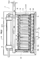
- FIG. 1 is an overall configuration diagram showing a solid oxide fuel cell (SOFC) according to an embodiment of the present invention.
- a solid oxide fuel cell (SOFC) 1 according to an embodiment of the present invention includes a fuel cell module 2 and an auxiliary unit 4.
- the fuel cell module 2 includes a housing 6, and a sealed space 8 is formed around the housing 6 via a heat storage material 7.
- the heat storage material 7 can store the heat generated in the fuel module 2, and can improve the thermal efficiency of the fuel cell module 2.
- a fuel cell assembly 12 that performs a power generation reaction with fuel gas and an oxidant (air) is disposed in a power generation chamber 10 that is a lower portion of the sealed space 8.
- the fuel cell assembly 12 includes ten fuel cell stacks 14 (see FIG. 5), and the fuel cell stack 14 includes 16 fuel cell unit 16 (see FIG. 4). Yes.
- the fuel cell assembly 12 has 160 fuel cell units 16, and all of these fuel cell units 16 are connected in series.
- a combustion chamber 18 is formed above the above-described power generation chamber 10 in the sealed space 8 of the fuel cell module 2.
- this combustion chamber 18 the remaining fuel gas that has not been used for the power generation reaction and the remaining oxidant (air) ) And combusted to generate exhaust gas.
- a reformer 20 for reforming the fuel gas is disposed above the combustion chamber 18, and the reformer 20 is heated to a temperature at which a reforming reaction can be performed by the combustion heat of the residual gas.
- an air heat exchanger 22 for receiving combustion heat and heating air is disposed above the reformer 20.
- the auxiliary unit 4 stores a pure water tank 26 that stores water from a water supply source 24 such as tap water and uses the filter to obtain pure water, and a water flow rate that adjusts the flow rate of the water supplied from the water storage tank.
- An adjustment unit 28 (such as a “water pump” driven by a motor) is provided.
- the auxiliary unit 4 also includes a gas shut-off valve 32 that shuts off the fuel gas supplied from a fuel supply source 30 such as city gas, a desulfurizer 36 for removing sulfur from the fuel gas, and a flow rate of the fuel gas.
- a fuel flow rate adjusting unit 38 (such as a “fuel pump” driven by a motor) is provided.
- the auxiliary unit 4 includes an electromagnetic valve 42 that shuts off air that is an oxidant supplied from the air supply source 40, a reforming air flow rate adjusting unit 44 that adjusts the flow rate of air, and a power generation air flow rate adjusting unit. 45 (such as an “air blower” driven by a motor), a first heater 46 for heating the reforming air supplied to the reformer 20, and a second for heating the power generating air supplied to the power generation chamber And a heater 48.
- the first heater 46 and the second heater 48 are provided in order to efficiently raise the temperature at startup, but may be omitted.
- a hot water production apparatus 50 to which exhaust gas is supplied is connected to the fuel cell module 2.
- the hot water production apparatus 50 is supplied with tap water from the water supply source 24, and the tap water is heated by the heat of the exhaust gas and supplied to a hot water storage tank of an external hot water heater (not shown).
- the fuel cell module 2 is provided with a control box 52 for controlling the amount of fuel gas supplied and the like. Furthermore, the fuel cell module 2 is connected to an inverter 54 that is a power extraction unit (power conversion unit) for supplying the power generated by the fuel cell module to the outside.
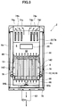
- FIG. 2 is a side sectional view showing a solid oxide fuel cell (SOFC) fuel cell module according to an embodiment of the present invention
- FIG. 3 is a sectional view taken along line III-III in FIG.
- the fuel cell assembly 12, the reformer 20, and the air heat exchange are sequentially performed from below.
- a vessel 22 is arranged.
- the reformer 20 is provided with a pure water introduction pipe 60 for introducing pure water and a reformed gas introduction pipe 62 for introducing reformed fuel gas and reforming air to the upstream end side thereof.
- a pure water introduction pipe 60 for introducing pure water
- a reformed gas introduction pipe 62 for introducing reformed fuel gas and reforming air to the upstream end side thereof.
- an evaporation unit 20a and a reforming unit 20b are formed in order from the upstream side, and the reforming unit 20b is filled with a reforming catalyst.
- the fuel gas and air mixed with the steam (pure water) introduced into the reformer 20 are reformed by the reforming catalyst filled in the reformer 20.
- the reforming catalyst a catalyst obtained by imparting nickel to the alumina sphere surface or a catalyst obtained by imparting ruthenium to the alumina sphere surface is appropriately used.
- a fuel gas supply pipe 64 is connected to the downstream end side of the reformer 20, and the fuel gas supply pipe 64 extends downward and further in an manifold 66 formed below the fuel cell assembly 12. It extends horizontally.
- a plurality of fuel supply holes 64 b are formed in the lower surface of the horizontal portion 64 a of the fuel gas supply pipe 64, and the reformed fuel gas is supplied into the manifold 66 from the fuel supply holes 64 b.
- a lower support plate 68 having a through hole for supporting the fuel cell stack 14 described above is attached above the manifold 66, and the fuel gas in the manifold 66 flows into the fuel cell unit 16. Supplied.
- the air heat exchanger 22 includes an air aggregation chamber 70 on the upstream side and two air distribution chambers 72 on the downstream side.
- the air aggregation chamber 70 and the air distribution chamber 72 include six air flow path tubes 74. Connected by.
- three air flow path pipes 74 form a set (74a, 74b, 74c, 74d, 74e, 74f), and the air in the air collecting chamber 70 is in each set. It flows into each air distribution chamber 72 from the air flow path pipe 74.
- the air flowing through the six air flow path pipes 74 of the air heat exchanger 22 is preheated by exhaust gas that burns and rises in the combustion chamber 18.
- An air introduction pipe 76 is connected to each of the air distribution chambers 72, the air introduction pipe 76 extends downward, and the lower end side communicates with the lower space of the power generation chamber 10, and the air that has been preheated in the power generation chamber 10. Is introduced.
- an exhaust gas chamber 78 is formed below the manifold 66. Further, as shown in FIG. 3, an exhaust gas passage 80 extending in the vertical direction is formed inside the front surface 6 a and the rear surface 6 b which are surfaces along the longitudinal direction of the housing 6, and the upper end side of the exhaust gas passage 80 is formed. Is in communication with the space in which the air heat exchanger 22 is disposed, and the lower end side is in communication with the exhaust gas chamber 78. Further, an exhaust gas discharge pipe 82 is connected to substantially the center of the lower surface of the exhaust gas chamber 78, and the downstream end of the exhaust gas discharge pipe 82 is connected to the above-described hot water producing apparatus 50 shown in FIG. As shown in FIG. 2, an ignition device 83 for starting combustion of fuel gas and air is provided in the combustion chamber 18.
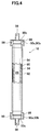
- FIG. 4 is a partial cross-sectional view showing a fuel cell unit of a solid oxide fuel cell (SOFC) according to an embodiment of the present invention.
- the fuel cell unit 16 includes a fuel cell 84 and inner electrode terminals 86 respectively connected to the vertical ends of the fuel cell 84.
- the fuel cell 84 is a tubular structure extending in the vertical direction, and includes a cylindrical inner electrode layer 90 that forms a fuel gas flow path 88 therein, a cylindrical outer electrode layer 92, an inner electrode layer 90, and an outer side.
- An electrolyte layer 94 is provided between the electrode layer 92 and the electrode layer 92.
- the inner electrode layer 90 is a fuel electrode through which fuel gas passes and becomes a ( ⁇ ) electrode, while the outer electrode layer 92 is an air electrode in contact with air and becomes a (+) electrode.
- the upper portion 90 a of the inner electrode layer 90 includes an outer peripheral surface 90 b and an upper end surface 90 c exposed to the electrolyte layer 94 and the outer electrode layer 92.
- the inner electrode terminal 86 is connected to the outer peripheral surface 90b of the inner electrode layer 90 through a conductive sealing material 96, and is further in direct contact with the upper end surface 90c of the inner electrode layer 90, thereby Electrically connected.
- a fuel gas passage 98 communicating with the fuel gas passage 88 of the inner electrode layer 90 is formed at the center of the inner electrode terminal 86.
- the inner electrode layer 90 includes, for example, a mixture of Ni and zirconia doped with at least one selected from rare earth elements such as Ca, Y, and Sc, and Ni and ceria doped with at least one selected from rare earth elements.
- the mixture is formed of at least one of Ni and a mixture of lanthanum garade doped with at least one selected from Sr, Mg, Co, Fe, and Cu.
- the electrolyte layer 94 is, for example, zirconia doped with at least one selected from rare earth elements such as Y and Sc, ceria doped with at least one selected from rare earth elements, lanthanum gallate doped with at least one selected from Sr and Mg, Formed from at least one of the following.
- the outer electrode layer 92 includes, for example, lanthanum manganite doped with at least one selected from Sr and Ca, lanthanum ferrite doped with at least one selected from Sr, Co, Ni and Cu, Sr, Fe, Ni and Cu. It is formed from at least one of lanthanum cobaltite doped with at least one selected from the group consisting of silver and silver.
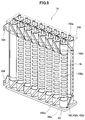
- FIG. 5 is a perspective view showing a fuel cell stack of a solid oxide fuel cell (SOFC) according to an embodiment of the present invention.
- the fuel cell stack 14 includes 16 fuel cell units 16, and the lower end side and the upper end side of these fuel cell units 16 are a ceramic lower support plate 68 and an upper side, respectively. It is supported by the support plate 100.
- the lower support plate 68 and the upper support plate 100 are formed with through holes 68a and 100a through which the inner electrode terminal 86 can pass.
- the current collector 102 includes a fuel electrode connection portion 102a that is electrically connected to an inner electrode terminal 86 attached to the inner electrode layer 90 that is a fuel electrode, and an entire outer peripheral surface of the outer electrode layer 92 that is an air electrode. And an air electrode connecting portion 102b electrically connected to each other.
- the air electrode connecting portion 102b is formed of a vertical portion 102c extending in the vertical direction on the surface of the outer electrode layer 92 and a plurality of horizontal portions 102d extending in a horizontal direction along the surface of the outer electrode layer 92 from the vertical portion 102c. Has been.
- the fuel electrode connection portion 102a is linearly directed obliquely upward or obliquely downward from the vertical portion 102c of the air electrode connection portion 102b toward the inner electrode terminal 86 positioned in the vertical direction of the fuel cell unit 16. It extends.
- the inner electrode terminals 86 at the upper end and the lower end of the two fuel cell units 16 located at the ends of the fuel cell stack 14 are external terminals, respectively. 104 is connected. These external terminals 104 are connected to the external terminals 104 (not shown) of the fuel cell unit 16 at the end of the adjacent fuel cell stack 14, and as described above, the 160 fuel cell units 16 Everything is connected in series.
- FIG. 6 is a block diagram illustrating a solid oxide fuel cell (SOFC) according to an embodiment of the present invention.
- the solid oxide fuel cell 1 includes a control unit 110, and the control unit 110 includes operation buttons such as “ON” and “OFF” for operation by the user.
- a device 112 a display device 114 for displaying various data such as a power generation output value (wattage), and a notification device 116 for issuing an alarm (warning) in an abnormal state are connected.
- the notification device 116 may be connected to a remote management center and notify the management center of an abnormal state.
- the combustible gas detection sensor 120 is for detecting a gas leak, and is attached to the fuel cell module 2 and the auxiliary unit 4.
- the CO detection sensor 122 detects whether or not CO in the exhaust gas originally discharged to the outside through the exhaust gas passage 80 or the like leaks to an external housing (not shown) that covers the fuel cell module 2 and the auxiliary unit 4. Is to do.
- the hot water storage state detection sensor 124 is for detecting the temperature and amount of hot water in a water heater (not shown).
- the power state detection sensor 126 is for detecting the current and voltage of the inverter 54 and the distribution board (not shown).
- the power generation air flow rate detection sensor 128 is for detecting the flow rate of power generation air supplied to the power generation chamber 10.
- the reforming air flow sensor 130 is for detecting the flow rate of the reforming air supplied to the reformer 20.
- the fuel flow sensor 132 is for detecting the flow rate of the fuel gas supplied to the reformer 20.
- the water flow rate sensor 134 is for detecting the flow rate of pure water (steam) supplied to the reformer 20.
- the water level sensor 136 is for detecting the water level of the pure water tank 26.
- the pressure sensor 138 is for detecting the pressure on the upstream side outside the reformer 20.
- the exhaust temperature sensor 140 is for detecting the temperature of the exhaust gas flowing into the hot water production apparatus 50.
- the power generation chamber temperature sensor 142 is provided on the front side and the back side in the vicinity of the fuel cell assembly 12, and detects the temperature in the vicinity of the fuel cell stack 14 to thereby detect the fuel cell stack. 14 (ie, the fuel cell 84 itself) is estimated.
- the combustion chamber temperature sensor 144 is for detecting the temperature of the combustion chamber 18.
- the exhaust gas chamber temperature sensor 146 is for detecting the temperature of the exhaust gas in the exhaust gas chamber 78.
- the reformer temperature sensor 148 is for detecting the temperature of the reformer 20, and calculates the temperature of the reformer 20 from the inlet temperature and the outlet temperature of the reformer 20.
- the outside air temperature sensor 150 is for detecting the temperature of the outside air when the solid oxide fuel cell (SOFC) is disposed outdoors. Further, a sensor for measuring the humidity or the like of the outside air may be provided.
- SOFC solid oxide fuel cell
- Signals from these sensors are sent to the control unit 110, and the control unit 110, based on data based on these signals, the water flow rate adjustment unit 28, the fuel flow rate adjustment unit 38, the reforming air flow rate adjustment unit 44, A control signal is sent to the power generation air flow rate adjusting unit 45 to control each flow rate in these units. Further, the control unit 110 sends a control signal to the inverter 54 to control the power supply amount.
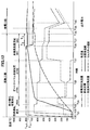
- FIG. 7 is a time chart showing the operation at the time of startup of the solid oxide fuel cell (SOFC) according to one embodiment of the present invention.
- reforming air is supplied from the reforming air flow rate adjustment unit 44 to the reformer 20 of the fuel cell module 2 via the first heater 46.
- the power generation air is supplied from the power generation air flow rate adjustment unit 45 to the air heat exchanger 22 of the fuel cell module 2 via the second heater 48, and this power generation air is supplied to the power generation chamber 10 and the combustion chamber.
- the fuel gas is also supplied from the fuel flow rate adjustment unit 38, and the fuel gas mixed with the reforming air passes through the reformer 20, the fuel cell stack 14, and the fuel cell unit 16, and It reaches the combustion chamber 18.
- the ignition device 83 is ignited to burn the fuel gas and air (reforming air and power generation air) in the combustion chamber 18.
- Exhaust gas is generated by the combustion of the fuel gas and air
- the power generation chamber 10 is warmed by the exhaust gas, and when the exhaust gas rises in the sealed space 8 of the fuel cell module 2,
- the fuel gas containing the reforming air is warmed, and the power generation air in the air heat exchanger 22 is also warmed.
- the fuel gas mixed with the reforming air is supplied to the reformer 20 by the fuel flow rate adjusting unit 38 and the reforming air flow rate adjusting unit 44.
- the heated fuel gas is supplied to the lower side of the fuel cell stack 14 through the fuel gas supply pipe 64, whereby the fuel cell stack 14 is heated from below, and the combustion chamber 18 also has the fuel gas and air.
- the fuel cell stack 14 is also heated from above, and as a result, the fuel cell stack 14 can be heated substantially uniformly in the vertical direction. Even if the partial oxidation reforming reaction POX proceeds, the combustion reaction between the fuel gas and air continues in the combustion chamber 18.
- the water flow rate is determined based on the temperature of the reformer 20 detected by the reformer temperature sensor 148 and the temperature of the fuel cell stack 14 detected by the power generation chamber temperature sensor 142.
- the adjustment unit 28, the fuel flow rate adjustment unit 38, and the reforming air flow rate adjustment unit 44 start supplying a gas in which fuel gas, reforming air, and water vapor are mixed in advance to the reformer 20.
- an autothermal reforming reaction ATR in which the partial oxidation reforming reaction POX described above and a steam reforming reaction SR described later are used together proceeds. Since the autothermal reforming reaction ATR is thermally balanced internally, the reaction proceeds in the reformer 20 in a thermally independent state.
- the temperature of the reformer 20 detected by the reformer temperature sensor 146 and the temperature of the fuel cell stack 14 detected by the power generation chamber temperature sensor 142 Based on the above, the supply of reforming air by the reforming air flow rate adjusting unit 44 is stopped and the supply of water vapor by the water flow rate adjusting unit 28 is increased. As a result, the reformer 20 is supplied with a gas that does not contain air and contains only fuel gas and water vapor, and the steam reforming reaction SR of formula (3) proceeds in the reformer 20.
- this steam reforming reaction SR is an endothermic reaction, the reaction proceeds while maintaining a heat balance with the combustion heat from the combustion chamber 18. At this stage, since the fuel cell module 2 is in the final stage of start-up, the power generation chamber 10 is heated to a sufficiently high temperature. Therefore, even if the endothermic reaction proceeds, the power generation chamber 10 is greatly reduced in temperature. There is nothing. Even if the steam reforming reaction SR proceeds, the combustion reaction continues in the combustion chamber 18.
- the partial oxidation reforming reaction POX, the autothermal reforming reaction ATR, and the steam reforming reaction SR proceed in sequence, thereby causing the inside of the power generation chamber 10 to The temperature gradually increases.
- power is taken out from the fuel cell module 2 to the inverter 54. That is, power generation is started. Due to the power generation of the fuel cell module 2, the fuel cell 84 itself also generates heat, and the temperature of the fuel cell 84 also rises.
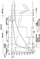
- FIG. 8 is a time chart showing the operation when the solid oxide fuel cell (SOFC) is stopped according to this embodiment.
- the fuel flow rate adjustment unit 38 and the water flow rate adjustment unit 28 are operated to supply fuel gas and water vapor to the reformer 20. Reduce the amount.
- the amount of fuel gas and water vapor supplied to the reformer 20 is reduced, and at the same time, the fuel cell module for generating air by the reforming air flow rate adjusting unit 44
- the supply amount into 2 is increased, the fuel cell assembly 12 and the reformer 20 are cooled by air, and these temperatures are lowered.
- the temperature of the power generation chamber decreases to a predetermined temperature, for example, 400 ° C.
- the supply of fuel gas and steam to the reformer 20 is stopped, and the steam reforming reaction SR of the reformer 20 is ended.
- This supply of power generation air continues until the temperature of the reformer 20 decreases to a predetermined temperature, for example, 200 ° C., and when this temperature is reached, the power generation air from the power generation air flow rate adjustment unit 45 is supplied. Stop supplying.
- the steam reforming reaction SR by the reformer 20 and the cooling by the power generation air are used in combination.
- the operation of the fuel cell module can be stopped.
- FIG. 9 is a basic operation table showing the start-up process procedure of the fuel cell 1, and is used when the amount of heat remaining in the fuel cell module 2 at the start of start-up is less than a predetermined amount and there is no risk of overheating as described later. It is what As shown in FIG. 9, in the start-up process, the control unit 110 sequentially executes each operation control state (combustion operation process, POX1 process, POX2 process, ATR1 process, ATR2 process, SR1 process, SR2 process) in time sequence, It is comprised so that it may transfer to a power generation process.
- operation control state combustion operation process, POX1 process, POX2 process, ATR1 process, ATR2 process, SR1 process, SR2 process
- the POX1 process and the POX2 process are processes in which a partial oxidation reforming reaction is performed in the reformer 20.
- the ATR1 process and the ATR2 process are processes in which an autothermal reforming reaction is performed in the reformer 20.
- the SR1 process and the SR2 process are processes in which a steam reforming reaction is performed in the reformer 20.
- Each of the POX process, the ATR process, and the SR process is subdivided into two parts. However, the present invention is not limited to this.
- the control unit 110 sends a signal to the reforming air flow rate adjustment unit 44 and the power generation air flow rate adjustment unit 45 to start them, and the reforming air ( (Oxidant gas) and air for power generation are supplied to the fuel cell module 2.
- the supply amount of reforming air that is started to be supplied at time t 0 is 10.0 (L / min)
- the supply amount of power generation air is 100.0 (L / min). It is set (see “combustion operation” step in FIG. 9).
- the control unit 110 sends a signal to the fuel flow rate adjustment unit 38 and starts supplying fuel gas to the reformer 20.
- the fuel gas and reforming air sent to the reformer 20 are sent into each fuel cell unit 16 via the reformer 20, the fuel gas supply pipe 64, and the manifold 66.
- the fuel gas and reforming air sent into each fuel cell unit 16 flow out from the upper end of the fuel gas flow path 98 of each fuel cell unit 16.
- the supply amount of the fuel gas to be supplied at time t 1 is set to 6.0 (L / min) (see “combustion operation” step in FIG. 9).
- the control unit 110 sends a signal to the ignition device 83 to ignite the fuel gas flowing out from the fuel cell unit 16.
- the fuel gas is combusted in the fuel chamber 18, and the reformer 20 disposed above the fuel gas is heated by the exhaust gas generated thereby, and the combustion chamber 18, the power generation chamber 10, and the inside thereof
- the temperature of the arranged fuel cell stack 14 (hereinafter referred to as “cell stack temperature”) also rises (see times t 2 to t 3 in FIG. 7).
- the fuel cell unit 16 including the fuel gas passage 98 and the upper end portion thereof correspond to a combustion portion.
- reformer temperature When the temperature of the reformer 20 (hereinafter referred to as “reformer temperature”) rises to about 300 ° C. by heating the reformer 20, a partial oxidation reforming reaction (POX) occurs in the reformer 20. (Time t 3 in FIG. 7: POX1 process starts). Since the partial oxidation reforming reaction is an exothermic reaction, the reformer 20 is also heated by the reaction heat due to the occurrence of the partial oxidation reforming reaction (time t 3 to t 5 in FIG. 7).
- the control unit 110 sends a signal to the fuel flow rate adjustment unit 38 to reduce the fuel gas supply amount and the reforming air.
- a signal is sent to the flow rate adjustment unit 38 to increase the supply amount of reforming air (time t 4 in FIG. 7: POX2 process start). Accordingly, the fuel gas supply amount is changed to 5.0 (L / min), and the reforming air supply amount is changed to 18.0 (L / min) (see the “POX2” step in FIG. 9).
- These supply amounts are appropriate supply amounts for generating the partial oxidation reforming reaction.
- the controller 110 changes the reforming air flow rate adjustment unit 44. Is sent to the water flow rate adjusting unit 28 to start the water supply (ATR1 process start). As a result, the reforming air supply amount is changed to 8.0 (L / min), and the water supply amount is set to 2.0 (cc / min) (see “ATR1” step in FIG. 9).
- ATR1 autothermal reforming
- the cell stack temperature is measured by the power generation chamber temperature sensor 142 disposed in the power generation chamber 10.
- the temperature detected by the power generation chamber temperature sensor reflects the cell stack temperature
- the cell is detected by the power generation chamber temperature sensor arranged in the power generation chamber.
- the stack temperature can be grasped.
- the cell stack temperature means a temperature measured by an arbitrary sensor that indicates a value reflecting the cell stack temperature.
- the control unit 110 sends a signal to the fuel flow rate adjustment unit 38. Reduce the fuel gas supply. Further, the control unit 110 sends a signal to the reforming air flow rate adjustment unit 44 to reduce the reforming air supply amount and sends a signal to the water flow rate adjustment unit 28 to increase the water supply amount (ATR2). Process start). As a result, the fuel gas supply amount is changed to 4.0 (L / min), the reforming air supply amount is changed to 4.0 (L / min), and the water supply amount is 3.0 (cc / min). (Refer to “ATR2” step in FIG. 9).
- the ratio of the partial oxidation reforming reaction that is an exothermic reaction is reduced in the reformer 20, and the steam reforming that is an endothermic reaction.
- the rate of reaction increases.
- an increase in the reformer temperature is suppressed, and on the other hand, the fuel cell stack 14 is heated by the gas flow received from the reformer 20, whereby the cell stack temperature rises to catch up with the reformer temperature.
- the temperature difference between the two is reduced, and the temperature is stably increased.
- the controller 110 sends a signal to the reforming air flow rate adjustment unit 44 and stops the supply of the reforming air. Further, the control unit 110 sends a signal to the fuel flow rate adjustment unit 38 to decrease the fuel gas supply amount, and sends a signal to the water flow rate adjustment unit 28 to increase the water supply amount (SR1 process start). Accordingly, the fuel gas supply amount is changed to 3.0 (L / min), and the water supply amount is changed to 8.0 (cc / min) (see the “SR1” process in FIG. 9). When the supply of the reforming air is stopped, the partial oxidation reforming reaction does not occur in the reformer 20, and SR in which only the steam reforming reaction occurs is started.
- the control unit 110 sends a signal to the fuel flow rate adjustment unit 38 to reduce the fuel gas supply amount, and sends a signal to the water flow rate adjustment unit 28 to reduce the water supply amount. Further, the control unit 110 sends a signal to the power generation air flow rate adjustment unit 45 to reduce the supply amount of the power generation amount air (SR2 process start).
- the fuel gas supply amount is changed to 2.3 (L / min)
- the water supply amount is changed to 6.3 (cc / min)
- the power generation air supply amount is 80.0 (L / min).
- the fuel gas supply amount and the water supply amount are kept high in order to raise the reformer temperature and the stack temperature to near the temperature at which power generation is possible. Thereafter, in the SR2 step, the fuel gas flow rate and the water supply amount are reduced, the temperature distributions of the reformer temperature and the cell stack temperature are settled, and are stabilized in a temperature range where power generation is possible.
- Control unit 110 in the SR2 step, over the time t 8 to time t 12, the respective supply amounts including the fuel gas supply amount is reduced to the supply amount for SR2 process at a predetermined reduction rate, the predetermined at time t 12
- the power generation transition period T 1 is maintained.
- the reformer 20 and the fuel cell stack 14 or the like holds the reformer 20 and the fuel cell stack 14 or the like to a predetermined state in which the power generation transition period T 1 only stable, reformer in the fuel cell module 2 temperature and the cell stack temperature and the like
- the temperature distribution can be calmed down. That is, the power generation transition period T 1 functions as a stabilization period after the supply amount is reduced.
- the fuel cell module 2 When the reformer temperature is 650 ° C. or higher and the stack temperature is 700 ° C. or higher at time t 9 in FIG. 7 after the predetermined power generation transition period T 1 has elapsed, the fuel cell module 2 to output power to the inverter 54 from start migrating to power generation in the power generation process (time in FIG. 7 t 9: power step starts).
- the power generation process, the control unit 110 during the time t 10 from the time t 9 maintains the fuel gas supply amount and the water supply amount constant.
- the reformer temperature falls within a proper temperature range below a predetermined threshold temperature T th (750 ° C. in this example) in the SR step where the temperature is highest in the startup step. Retained.
- the threshold temperature T th is set to a temperature lower than the abnormality determination temperature (800 ° C. in this example) for forcibly stopping the fuel cell 1 abnormally because the reformer 20 may be deteriorated or damaged. Yes.
- control unit 110 sends a signal to the fuel flow rate adjustment unit 38 and the water flow rate adjustment unit 28 to change the fuel gas supply amount and the water supply amount so as to follow the output power.
- the control unit 110 sends a signal to the fuel flow rate adjustment unit 38 and the water flow rate adjustment unit 28 to change the fuel gas supply amount and the water supply amount so as to follow the output power.
- the fuel cell module 2 is provided with the heat storage material 7 as the heat storage means around the housing 6 as the module storage chamber in order to improve the thermal efficiency, so that the heat generated inside does not escape to the outside. It is configured so that it can be used effectively.
- the fuel cell device 1 is operated, and the fuel cell module 2 including the heat storage material 7 as a whole enters a stop operation in a state where the temperature rises, and then the heat storage material 7 or the like accumulates a large amount of heat before the restart process. If it enters, it will become easy to heat up the component (especially reformer 20) in the fuel cell module 2 compared with the time of starting from a normal room temperature state.
- the heat generated in the reformer 20 in the partial oxidation reforming reaction that is an exothermic reaction is not limited to the temperature of the reformer 20 itself when starting from a normal room temperature state, but other components and heat storage materials. 7 is discharged out of the reformer 20 to raise the temperature.
- the heat generated in the partial oxidation reforming reaction is mainly used to raise the temperature of the reformer 20, and the reformer 20 The heating rate is increased. Thereby, for example, the reformer 20 may be deteriorated due to excessive temperature rise.
- the excessive temperature increase suppression control is performed according to this state. Is performed, and an appropriate restart is performed to prevent overheating.
- This excessive temperature rise suppression control is normally used to detect the fuel gas supply amount and the water supply amount at the time of transition to the power generation process when the temperature increase assist state is detected. This is fuel gas reduction control that shifts to the power generation process in a state where the supply amount is lower than the supply amount at the time of startup.
- FIG. 10 shows a case where the reformer temperature rise rate is faster than in the case of FIG.
- differences from the normal startup operation and processing described with reference to FIGS. 7 and 9 will be mainly described.
- the activation state from time t 20 to time t 28 is substantially the same as the activation state from time t 0 to time t 8 in FIG. Since the temperature rise in the reformer 20 is earlier than the temperature rise of the fuel cell stack 14 as compared to the normal, the temperature of the reformer 20 before the time t 27, the transition temperature to the SR1 step from ATR2 step It exceeds the condition of 650 ° C. Then, at time t 27 when the cell stack temperature reaches 600 ° C., which is the transition temperature condition, both transition conditions are satisfied, so that the control unit 110 shifts from the ATR2 process to the SR1 process.
- the transition conditions from the SR1 process to the SR2 process are a reformer temperature of 650 ° C. or higher and a cell stack temperature of 650 ° C. or higher (SR2 transition condition).
- SR1 process proceeds even reformer temperature continues to rise, at a time t 28 to the cell stack temperature reaches a is 650 ° C. transition temperature of the SR2 step, the reformer temperature is transition temperature to the SR2 step
- the temperature is raised above the threshold temperature T th exceeding the condition of 650 ° C. However, in this case, the reformer temperature does not reach the second threshold temperature T th2 (780 ° C. in this example) set between the threshold temperature T th and the abnormality determination temperature.
- the control unit 110 serving as a determination unit operates as shown in FIG.
- a large amount of heat is accumulated in the fuel cell module 2 because the temperature rise rate of the reformer temperature is faster than the process of raising the transition temperature, which is the reference for the reformer temperature and cell stack temperature shown in the table. In this state, the temperature rise of the reformer 20 is promoted due to the amount of heat, or the temperature rise rate is faster than the normal startup, that is, the temperature rise promoted state. judge.
- the temperature rise rate of the reformer temperature is faster than the rate of temperature rise of the cell stack temperature, the temperature difference between the two becomes larger than usual, and the cell stack temperature reaches the transition temperature.
- the reformer temperature has reached the threshold temperature Tth that is higher than the transition temperature by a predetermined temperature or more, it is determined that the temperature increase assisting state has been reached.
- control unit 110 serving as a determination unit calculates a temperature increase of the reformer temperature with respect to the threshold temperature T th at the end of the SR1 process, and estimates the degree of the temperature increase promotion state based on the temperature increase. That is, it is determined that the higher the reformer temperature is higher than the threshold temperature Tth , the higher the temperature of the reformer 20 and the fuel cell stack 14 is increased by the remaining heat amount (that is, the degree of excessive temperature increase).
- the control part 110 reduces the fuel gas supply amount and the water supply amount at a predetermined reduction rate in the SR2 step (temperature reduction period T 2 ).
- a predetermined reduction rate in the SR2 step temperature reduction period T 2
- the control part 110 reduces the fuel gas supply amount and the water supply amount at a predetermined reduction rate in the SR2 step (temperature reduction period T 2 ).
- the temperature reduction period T 2 by reducing the fuel gas supply amount and the water supply amount, an increase in the reformer temperature is suppressed, and the reformer temperature gradually decreases. If the fuel gas supply amount and the water supply amount are reduced, the steam reforming reaction, which is an endothermic reaction, is suppressed, which is disadvantageous as an effect of suppressing an increase in reformer temperature.
- the outflow amount of the reformed fuel gas flowing out from the fuel battery cell unit 16 is also reduced, and the exhaust gas amount from the combustion section that heats the reformer 20 is reduced. Therefore, the increase in the reformer temperature is suppressed as a whole.
- the cell stack temperature gradually increases to catch up with the reformer temperature by receiving the gas flow from the reformer 20 in the SR2 step, and reaches a temperature at which power generation is possible.
- the fuel gas supply amount is reduced more than usual.
- the reduction in the fuel gas supply amount is compensated by the remaining heat amount, so that the cell stack temperature is reliably increased to the power generation possible temperature. Can be warmed.
- the controller 110 monitors the reformer temperature and adjusts the fuel gas supply amount and the water supply amount based on the change in the reformer temperature, more specifically, the reformer temperature is the threshold temperature T.
- the feedback control is performed so as to reduce the fuel gas supply amount and the water supply amount at a constant reduction rate until it becomes th or less.
- the reformer temperature decreases to the threshold temperature T th at time t 32 without reaching the second threshold temperature T th2 or the third threshold temperature T th3 in FIG. 10 due to the reduction of the fuel gas supply amount.
- the controller 110 stops the reduction of the fuel gas supply amount and the water supply amount, ends the temperature reduction period T 2, and supplies at this time Keep in quantity.
- control unit 110 waits for the temperature distribution power transition period T 1 is passed from the time of holding the supply amount constant (time t 32) is stabilized, when the power transition period T 1 is elapsed (time At t 29 ), the SR2 process is shifted to the power generation process on condition that the reformer temperature and the cell stack temperature satisfy the transition temperature conditions (power generation process transition conditions) of 650 ° C. or higher and 700 ° C. or higher, respectively.
- these supply amounts are The value is reduced from each supply amount in the SR2 process shown in the operation table of FIG. 9, and the process proceeds to the power generation process in a state where the fuel gas supply amount and the water supply amount are reduced compared to the normal startup. .
- the period for reducing the fuel gas supply amount and the water supply amount becomes longer.
- the amount of reduction increases. Therefore, as the temperature difference between the reformer temperature and the threshold temperature T th at the end of the SR1 process is larger, the fuel gas supply amount and the water supply amount at the time of shifting to the power generation process are lower than the supply amounts at the normal time.
- the cell stack temperature When shifting to the power generation process, the cell stack temperature temporarily rises due to a power generation reaction in the fuel cell stack 14. Along with this, the reformer temperature also rises. However, since the fuel gas supply amount is reduced at the time of the power generation process transition compared to the normal startup, the amount of surplus reformed fuel gas burned in the combustion section is also reduced, thereby reducing the exhaust gas. Since the amount decreases, the temperature rise of the reformer 20 is suppressed. Therefore, in FIG. 10, the reformer temperature exceeds the threshold temperature T th immediately after the power generation process is shifted, but thereafter, the fuel gas supply amount and the water supply amount are further reduced (from time t 30 ). The temperature is prevented from rising and maintained within an appropriate temperature range without exceeding the abnormality determination temperature.
- the rate of increase of the reformer temperature is faster than the rate of increase of the cell stack temperature compared with the normal startup, but the influence of the temperature rise due to the residual heat amount is not so much. If it is not large, the fuel gas supply amount at the time of transition to the power generation process during the SR2 step is reduced from the fuel gas supply amount at the time of normal startup, so that the power generation process, in particular, the transition to the power generation process and the power generation process In a predetermined period after the transition, it is possible to prevent the reformer temperature and the cell stack temperature from being overheated to a predetermined value (abnormality determination temperature) that causes deterioration or damage.
- a predetermined value abnormality determination temperature
- the fuel gas supply amount and the water supply amount are decreased at a constant reduction rate from the end of the SR1 step. You may comprise so that it may reduce to a supply amount in one step or several steps. Further, in accordance with the temperature increase of the reformer temperature relative to the threshold temperature Tth at the end of the SR1 process, the controller 110 increases the reduction amount of each of the fuel gas supply amount and the water supply amount as the increase temperature component increases. It may be configured to set and / or set the temperature reduction period T 2 to be long.
- the temperature increase promotion state is determined during the SR process, and the fuel gas supply amount is reduced in the SR2 process.
- the present invention is not limited to this, and the temperature increase is similarly performed in the POX process and the ATR process. You may comprise so that a promotion state may be determined and fuel gas supply amount may be reduced.
- the control unit 110 determines that the temperature increase is in an enhanced state, and in the SR2 step, supplies fuel gas.
- the amount and the water supply amount are reduced at a predetermined reduction rate (time t 28 to t 33 ).
- the controller 110 reduces the maximum temperature.
- the period T max has elapsed, the reduction of the fuel gas supply amount and the water supply amount is stopped, and the supply amount at this time is held.
- the control unit 110 Stop reducing supply.
- This example is an example in which the maximum temperature reduction period T max has passed without the reformer temperature reaching the second threshold temperature T th2 or the third threshold temperature T th3 .
- control unit 110 waits for the temperature distribution power transition period T 1 is passed from the time of holding the supply amount constant (time t 33) is stabilized, when the power transition period T 1 is elapsed (time At t 34 ), the SR2 process is shifted to the power generation process on condition that the reformer temperature and the cell stack temperature satisfy the transition temperature conditions (power generation process transition conditions) of 650 ° C. or higher and 700 ° C. or higher, respectively.
- the power generation transition period T 1 is set to a fixed value, and the degree of the temperature increase promotion state, that is, the magnitude of the temperature rise of the reformer temperature relative to the threshold temperature T th at the end of the SR1 step. Does not change. That is, the deviation in temperature distribution in which there is a local high temperature location in the fuel cell module 2 cannot be directly measured and is difficult to estimate. For this reason, in any situation, the power generation transition period T 1 is fixed so that the temperature distribution can settle and stabilize in a steady state before the process can proceed to the power generation process.
- the cell stack temperature and the reformer temperature temporarily increase due to the power generation reaction in the fuel cell stack 14. It is sufficiently reduced, the reformer temperature does not reach the second threshold temperature T th2 during the elapse of the maximum temperature reduction period T max , and there is a temperature margin from the threshold temperature T th to the abnormality determination temperature. For this reason, such a temporary temperature rise prevents the reformer temperature from reaching the abnormality determination temperature.
- the cell stack temperature gradually rises so as to catch up with the reformer temperature by the inflow gas from the reformer 20, and also due to the power generation reaction and Joule heat in the fuel cell stack 14. Raise the temperature. Thereby, the cell stack temperature can be maintained at the power generation operating temperature.
- the reformer temperature is generating step during migration, the fuel gas supply amount and the water supply amount has been sufficiently reduced than normal, (time t 35 Since then is further reduced fuel gas supply amount ⁇ ) After the temporary temperature rise immediately after the transition to the power generation process, the temperature rise is suppressed and maintained in an appropriate temperature range.
- the temperature distribution is made appropriate by shifting to the power generation process at an early stage. It is configured as follows.
- the reformer temperature at the end of the SR1 step is equal to or higher than a second threshold temperature T th2 that is a predetermined temperature higher than the threshold temperature T th.
- a second threshold temperature T th2 that is a predetermined temperature higher than the threshold temperature T th.
- the control unit 110 determines that the temperature increase is promoted, and in the SR2 process, the fuel gas supply amount and the water supply amount are determined in advance. (Time t 28 to t 37 ). However, since the reformer temperature at SR1 process end it is the second threshold temperature T th2 or more, the control unit 110, the temperature decrease period T 2 or maximum temperature reduction period according to the reformer temperature at SR1 process ends T max is shortened. In FIG. 12, the temperature reduction period T 2 or the maximum temperature reduction period T max is changed to a period T 3 that is shortened.
- control unit 110 reduces the fuel gas supply amount and the water supply amount at a constant reduction rate during the shortened temperature reduction period T 3 (time t 28 to t 37 ), and normalizes the start-up operation. after reducing below the supply amount at the time, the reduction of the fuel gas supply amount and the water supply amount is stopped at time t 37, to hold the feed amount at this point.
- control unit 110 waits for the temperature distribution power transition period T 1 is passed from the time of holding the supply amount constant (time t 37) is stabilized, when the power transition period T 1 is elapsed (time t 38) in the reformer temperature and the cell stack temperature is respectively 650 ° C. or higher, on condition that they meet 700 ° C. or more transition temperature (the power generation step shift condition), shifts from SR2 step to the power generation process.
- the fuel gas supply amount and the water supply amount are reduced in the SR2 process.
- the amount of residual heat is large as described above, an appropriate temperature distribution state is obtained by shifting to the power generation process at an early stage.
- the cell stack temperature and the reformer temperature temporarily rise due to the power generation reaction in the fuel cell stack 14, but the output power is initially set to be low.
- the gas supply amount and the water supply amount are also reduced to low values accordingly (from time t 39 on ).
- the reformer temperature starts to decrease before reaching the abnormality determination temperature, and is maintained in an appropriate temperature range during the power generation process.
- the cell stack temperature gradually rises to catch up with the reformer temperature by the inflow gas from the reformer 20, and also due to the power generation reaction and the Joule heat in the fuel cell stack 14. Raise the temperature. Thereby, the cell stack temperature can be maintained at the power generation operating temperature.
- the temperature reduction period T during which the fuel gas supply amount is reduced. 2 or the maximum temperature reduction period T max is shortened, and after the shortened temperature reduction period T 3 and the power generation transition period T 1 , the power generation process is shifted to an early stage.
- the temperature distribution can be stabilized in the power generation process in which the fuel gas supply amount is reduced without causing the reformer temperature and the cell stack temperature to reach the abnormality determination temperature.
- the reformer temperature is set to a third threshold temperature T th3 that is a predetermined temperature higher than the threshold temperature T th during the temperature reduction period T 2.
- T th3 a third threshold temperature
- the control unit 110 determines that the temperature increase is promoted, and in the SR2 process, the fuel gas supply amount and the water supply amount are determined in advance. (Time t 28 to t 41 ). However, although the fuel gas supply amount and the water supply amount are reduced, the reformer temperature further rises during the temperature reduction period T 2 , and the third threshold temperature T th3 (this example) is reached at time t 41 . In this case, the temperature reaches 780 ° C. When the reformer temperature reaches the third threshold temperature T th3 , the control unit 110 ends the temperature reduction period T 2 , stops reducing the fuel gas supply amount and the water supply amount, and maintains the supply amount at this time.
- the third threshold temperature T th3 is a temperature setting value between the threshold temperature T th and abnormality determination temperature may be the same temperature as the second threshold temperature T th2, than the second threshold temperature T th2 May be a high temperature or a low temperature.
- control unit 110 waits for the temperature distribution power transition period T 1 is passed from the time of holding the supply amount constant (time t 41) is stabilized, when the power transition period T 1 is elapsed (time At t 42 ), the SR2 process is shifted to the power generation process on condition that the reformer temperature and the cell stack temperature satisfy the transition temperature conditions (power generation process transition conditions) of 650 ° C. or higher and 700 ° C. or higher, respectively.
- the reformer temperature reaches the third threshold temperature T th3 even though the residual heat amount is large as in the example of FIG. 13 and the fuel gas supply amount and the water supply amount are reduced in the SR2 step. It is difficult to reduce the reformer temperature to an appropriate value by reducing the supply amount in the SR2 process. Therefore, in the present embodiment, when the residual heat amount is large as described above, an appropriate temperature distribution state is obtained by shifting to the power generation process as early as in the example of FIG. With this configuration, in this embodiment, the temperature distribution can be stabilized in the power generation process in which the fuel gas supply amount is reduced without causing the reformer temperature and the cell stack temperature to reach the abnormality determination temperature.
- Solid electrolyte fuel cell solid oxide fuel cell device
- Fuel cell module Auxiliary machine unit 6 Housing (module storage room) 7 heat storage material (heat storage means) DESCRIPTION OF SYMBOLS 10 Power generation chamber 12
- Fuel cell assembly 14
- Fuel cell stack 16
- Fuel cell unit 18
- Combustion chamber 20
- Reformer 22
- Air heat exchanger 28
- Water flow rate adjustment unit 38
- Reformation air flow rate adjustment unit 45
- Inverter 83
- Ignition device Fuel cell 110 Control unit (control means, determination means)
Landscapes
- Engineering & Computer Science (AREA)
- Chemical & Material Sciences (AREA)
- Life Sciences & Earth Sciences (AREA)
- Manufacturing & Machinery (AREA)
- Sustainable Development (AREA)
- Sustainable Energy (AREA)
- Chemical Kinetics & Catalysis (AREA)
- Electrochemistry (AREA)
- General Chemical & Material Sciences (AREA)
- Combustion & Propulsion (AREA)
- Fuel Cell (AREA)
Abstract
起動工程において燃料電池モジュール内の温度が上昇し過ぎることを防止する固体酸化物形燃料電池装置を提供する。 制御部110は、起動工程において、セルスタック温度及び改質器の温度に基づいて、改質器20に供給する燃料ガス、酸化剤ガス、水蒸気の供給量を制御し、POX工程、ATR工程、SR工程へ移行させた後、発電工程へ移行させ、各工程においてセルスタック温度及び改質器温度がそれぞれに対して設定された移行条件を満足した場合に、次の工程に移行させるように制御するよう構成されており、制御部110が昇温助長状態であると判定した場合、昇温助長状態であると判定していない場合と比べて、燃料ガス供給量を低減した状態で発電工程に移行させるように制御する。
Description
本発明は、固体酸化物形燃料電池装置に係わり、特に、起動中における改質器等の過昇温を防止する固体酸化物形燃料電池装置に関する。
従来、固体酸化物形燃料電池装置(SOFC)は、起動工程において、燃料ガスを改質器において改質する複数の工程、すなわち、部分酸化改質反応工程(POX工程)、オートサーマル改質反応工程(ATR工程)、水蒸気改質反応工程(SR工程)を経て、発電工程へ移行するように構成されている(例えば、特許文献1参照)。
SOFCでは、これらの工程を順に実行することにより、燃料電池モジュール収納室内に配置された改質器や燃料電池セルスタック等を動作温度まで昇温させることができる。
また、SOFCは、動作温度が600~800℃と高温であり、燃料電池モジュール収納室周囲に蓄熱材が配置されている。したがって、この蓄熱材は、動作中に多量の熱量を保持し、動作中の熱効率を向上させることができる。
また、SOFCは、動作温度が600~800℃と高温であり、燃料電池モジュール収納室周囲に蓄熱材が配置されている。したがって、この蓄熱材は、動作中に多量の熱量を保持し、動作中の熱効率を向上させることができる。
しかしながら、動作中のSOFCを一旦停止動作に移行させた後、再起動させる場合、上述のように蓄熱材には多量の熱量が蓄えられているため、通常の起動工程で起動させると、改質器や燃料電池セルスタックの温度が上昇し過ぎてしまうという問題があった。
例えば、通常の起動動作中において、改質器内での改質反応工程のうち、発熱反応であるPOX工程で発生した熱は、改質器自体を昇温させるが、改質器外の構成部材である蓄熱材等をも昇温させる。
これに対して、再起動動作中には、改質器外の構成部材が既にある程度の温度まで昇温されており、また、蓄熱材が多量の熱量を保持しているため、POX工程で発生した熱が、主に改質器を昇温するために用いられる。その結果、再起動動作中には、改質器が、通常の起動動作中よりも大きな昇温速度で昇温し、所定の動作温度を超えた状態となる過昇温が引き起こされるおそれがあった。そして、この過昇温により改質器が劣化したり損傷したりするおそれがあった。
本発明は、このような課題を解決するためになされたものであり、起動工程において、燃料電池モジュール内の温度が上昇し過ぎることを防止する固体酸化物形燃料電池装置を提供することを目的としている。
上記の目的を達成するために、本発明は、固体酸化物形燃料電池装置において、複数の燃料電池セルを組み合わせてなるセルスタックと、燃料電池セルに供給する燃料ガスを改質する改質器と、燃料電池セルを通過した余剰の燃料ガス又は改質された燃焼ガスを燃焼させることにより発生する排気ガスによって改質器及びセルスタックを加熱する燃焼部と、セルスタックの温度及び改質器の温度をそれぞれ検出する温度検出器と、セルスタック及び改質器を収納するモジュール収納室と、モジュール収納室の周囲に配置された蓄熱手段と、燃料電池装置の起動中に蓄熱手段が蓄積している熱量によって改質器及び/又はセルスタックの昇温が助長される状態である昇温助長状態であるか否かを判定する判定手段と、燃料電池装置の起動を制御する制御手段と、を備えており、制御手段は、燃料電池装置の起動工程において、セルスタックの温度及び改質器の温度に基づいて、改質器に供給する燃料ガス、酸化剤ガス、水蒸気の供給量を制御し、改質器で行われる燃料ガス改質反応工程をPOX工程、ATR工程、SR工程へ移行させた後、発電工程へ移行させ、各工程においてセルスタックの温度及び改質器の温度がそれぞれに対して設定された移行条件を満足した場合に、次の工程に移行させるように制御するよう構成されており、判定手段が昇温助長状態であると判定した場合、制御手段は、判定手段が昇温助長状態であると判定していない場合と比べて、燃料ガス供給量を低減した状態で発電工程に移行させるように制御することを特徴としている。
蓄熱手段に残存熱量が所定以上ある状況において燃料電池装置を起動する際、例えば、改質器内での部分酸化改質反応で生じた発生熱が蓄熱手段に奪われ難くなる。このため、特に、部分酸化改質反応が行われるPOX工程やATR工程において、改質器の温度上昇速度が大きくなり、通常の起動時と比べて改質器温度とセルスタック温度との温度差が大きくなる。
このような場合に通常起動時と同じ方法及び移行条件で起動を行うと、セルスタック温度の上昇を待っていると、改質器の温度が上昇し過ぎてしまい、例えば改質器の温度が異常判定温度以上に過昇温し、改質器の劣化・損傷が生じるおそれがあった。また、逆に、残存熱量の影響によって、セルスタック温度が上昇し過ぎることにより、燃料電池セルスタックに劣化が生じるおそれがあった。
本発明によれば、判定手段により、改質器及び/又はセルスタックが燃料電池装置の起動中に蓄熱手段が蓄積している残存熱量によって昇温される状態である昇温助長状態であるか否かを判定し、昇温助長状態であることが推定された場合は、発電工程移行時点における燃料ガス供給量を通常の起動時よりも低減することにより、燃焼部での排気ガスによる発熱量を抑制し、改質器の温度が上昇し過ぎること、すなわち過昇温を防止することができる。また、昇温助長状態であるので、燃料電池モジュール内の残存熱量によって、温度の不足分を補うことができるので、モジュール収納室内の温度分布を適正に保持することが可能である。
本発明において、好ましくは、判定手段が、昇温助長状態と判定した場合において、この判定に基づいて改質器及び/又はセルスタックが昇温される程度が大きいほど、制御手段は、発電工程への移行時における燃料ガス供給量をより低減する。
このように構成された本発明によれば、昇温助長状態において残存熱量が多く昇温の影響がより大きい場合には、それに対応して燃料ガス供給量をより低減する。これにより、本発明では、昇温される程度に応じて燃焼部による発熱量を減らすことによって、モジュール収納室内の温度分布を適正に保つことができる。
このように構成された本発明によれば、昇温助長状態において残存熱量が多く昇温の影響がより大きい場合には、それに対応して燃料ガス供給量をより低減する。これにより、本発明では、昇温される程度に応じて燃焼部による発熱量を減らすことによって、モジュール収納室内の温度分布を適正に保つことができる。
本発明において、好ましくは、制御手段は、SR工程における改質器の温度の変化に基づいて、燃料ガス供給量を調整する。
このように構成された本発明によれば、起動工程中の特定の時点で、残存熱量に基づく昇温助長状態の判定、及びそれに基づく燃料ガス供給量の低減を決定するのではなく、改質器温度の変化を所定期間にわたって継続して監視することにより、昇温助長状態の程度により適宜燃料ガス供給量を調整する。これにより、本発明では、燃料ガス供給量がフィードバック制御されることとなり、燃料ガス供給量を適切な値とすることができる。
このように構成された本発明によれば、起動工程中の特定の時点で、残存熱量に基づく昇温助長状態の判定、及びそれに基づく燃料ガス供給量の低減を決定するのではなく、改質器温度の変化を所定期間にわたって継続して監視することにより、昇温助長状態の程度により適宜燃料ガス供給量を調整する。これにより、本発明では、燃料ガス供給量がフィードバック制御されることとなり、燃料ガス供給量を適切な値とすることができる。
本発明において、好ましくは、制御手段は、SR工程のうち、発電工程に移行する前の第1の所定期間は、燃料ガス供給量を一定に保持する。
燃料ガス供給量を変化させている間は、モジュール室内の温度分布も変化し続けるため、局所的に高温箇所が生じている可能性がある。そこで、本発明では、燃料ガス供給量を発電工程へ移行する前に所定期間一定とすることにより、温度分布が落ち着いた定常状態となってから発電工程に移行することができる。これにより、本発明では、発電移行時に一時的にモジュール温度上昇が起きても、それに伴って過昇温となることを防止することができる。
燃料ガス供給量を変化させている間は、モジュール室内の温度分布も変化し続けるため、局所的に高温箇所が生じている可能性がある。そこで、本発明では、燃料ガス供給量を発電工程へ移行する前に所定期間一定とすることにより、温度分布が落ち着いた定常状態となってから発電工程に移行することができる。これにより、本発明では、発電移行時に一時的にモジュール温度上昇が起きても、それに伴って過昇温となることを防止することができる。
本発明において、好ましくは、制御手段は、改質器の温度が所定の第1の閾値温度以下に低下すると燃料ガス供給量を一定に保持し、第1の所定期間経過後に発電工程へ移行する。
このように構成された本発明によれば、改質器温度が第1の閾値温度以下の適正温度範囲になったことを確認することにより、残存熱量の影響による過昇温の発生可能性が小さくなった状態で発電工程に移行させることができる。更に、本発明では、第1の所定期間の経過を待つことにより、温度測定値にはあらわれない影響(例えば、モジュール室内の局所的な高温等)が軽減されるため、発電移行時の過昇温を防止することができる。
このように構成された本発明によれば、改質器温度が第1の閾値温度以下の適正温度範囲になったことを確認することにより、残存熱量の影響による過昇温の発生可能性が小さくなった状態で発電工程に移行させることができる。更に、本発明では、第1の所定期間の経過を待つことにより、温度測定値にはあらわれない影響(例えば、モジュール室内の局所的な高温等)が軽減されるため、発電移行時の過昇温を防止することができる。
本発明において、好ましくは、制御手段は、SR工程において燃料ガス供給量を低減した状態で第2の所定期間経過しても改質器の温度が第1の閾値温度以下に低下しない場合、第1の閾値温度以下に低下するのを待つことなく燃料ガス供給量を一定に保持し、第1の所定期間経過後に発電工程へ移行する。
このように構成された本発明によれば、第1の所定期間待っても改質器温度が第1の閾値温度以下の適正温度範囲に入らない場合は、燃料ガス供給量の少ない発電工程に早期に移行することによりモジュール室内を適切な温度分布とすることができる。
このように構成された本発明によれば、第1の所定期間待っても改質器温度が第1の閾値温度以下の適正温度範囲に入らない場合は、燃料ガス供給量の少ない発電工程に早期に移行することによりモジュール室内を適切な温度分布とすることができる。
本発明において、好ましくは、改質器の温度が、第1の閾値温度よりも高い所定の第2の閾値温度以上である場合、制御手段は、第2の所定期間を短くする。
残存熱量が大きく過昇温発生状態の程度が大きい場合は、SR工程において燃料ガス供給量を低減しても改質器温度が時間と共に下がらず、逆に上昇していくような状況となるおそれがある。本発明では、このような場合において、第2の所定期間を短くすることにより、早期に燃料ガス供給量の少ない発電工程に移行してモジュール室内を適切な温度分布にすることができる。
残存熱量が大きく過昇温発生状態の程度が大きい場合は、SR工程において燃料ガス供給量を低減しても改質器温度が時間と共に下がらず、逆に上昇していくような状況となるおそれがある。本発明では、このような場合において、第2の所定期間を短くすることにより、早期に燃料ガス供給量の少ない発電工程に移行してモジュール室内を適切な温度分布にすることができる。
本発明において、好ましくは、制御手段は、昇温助長状態の判定に基づいた改質器及び/又はセルスタックの昇温される程度によって、第1の所定期間の長さを変更しない。
モジュール収納室内で局所的に高温箇所があるかどうかは、直接測定できず、推定することも難しい。このため、本発明では、第1の所定期間を固定することにより、どのような状況でも温度分布が落ち着き定常状態となってから発電工程に移行できるように構成している。
モジュール収納室内で局所的に高温箇所があるかどうかは、直接測定できず、推定することも難しい。このため、本発明では、第1の所定期間を固定することにより、どのような状況でも温度分布が落ち着き定常状態となってから発電工程に移行できるように構成している。
本発明において、好ましくは、SR工程において、改質器の温度が第1の閾値温度よりも高く設定された所定の第3の閾値温度を超えた場合、改質器の温度が第1の閾値温度以下に低下するのを待つことなく、燃料ガス供給量を一定に保持し、第1の所定期間経過後に発電工程へ移行する。
改質器温度が異常判定温度付近の高温域に近づくような状況では、SR工程において改質器温度を第1の閾値温度以下の適正温度範囲に戻すことは難しい。したがって、本発明では、このような場合には、早期に燃料ガス供給量の少ない発電工程に移行し、改質器温度の低下を図るように構成されている。
改質器温度が異常判定温度付近の高温域に近づくような状況では、SR工程において改質器温度を第1の閾値温度以下の適正温度範囲に戻すことは難しい。したがって、本発明では、このような場合には、早期に燃料ガス供給量の少ない発電工程に移行し、改質器温度の低下を図るように構成されている。
本発明において、好ましくは、制御手段は、昇温助長状態の判定に基づいた改質器及び/又はセルスタックの昇温される程度によって、第1の所定期間の長さを変更しない。
モジュール収納室内で局所的に高温箇所があるかどうかは、直接測定できず、推定することも難しい。このため、本発明では、第1の所定期間を固定することにより、どのような状況でも温度分布が落ち着いて定常状態となってから発電工程に移行できるように構成している。
モジュール収納室内で局所的に高温箇所があるかどうかは、直接測定できず、推定することも難しい。このため、本発明では、第1の所定期間を固定することにより、どのような状況でも温度分布が落ち着いて定常状態となってから発電工程に移行できるように構成している。
本発明の固体酸化物形燃料電池装置によれば、起動工程において、燃料電池モジュール内の温度が上昇し過ぎることを防止することができる。
次に、添付図面を参照して、本発明の実施形態による固体酸化物形燃料電池装置又は固体電解質型燃料電池(SOFC)を説明する。
図1は、本発明の一実施形態による固体電解質型燃料電池(SOFC)を示す全体構成図である。この図1に示すように、本発明の一実施形態による固体電解質型燃料電池(SOFC)1は、燃料電池モジュール2と、補機ユニット4を備えている。
図1は、本発明の一実施形態による固体電解質型燃料電池(SOFC)を示す全体構成図である。この図1に示すように、本発明の一実施形態による固体電解質型燃料電池(SOFC)1は、燃料電池モジュール2と、補機ユニット4を備えている。
燃料電池モジュール2は、ハウジング6を備え、このハウジング6周囲には、蓄熱材7を介して密封空間8が形成されている。なお、蓄熱材7は、燃料モジュール2内で発生した熱を蓄熱することができるようになっており、燃料電池モジュール2の熱効率を向上させることができる。この密閉空間8の下方部分である発電室10には、燃料ガスと酸化剤(空気)とにより発電反応を行う燃料電池セル集合体12が配置されている。この燃料電池セル集合体12は、10個の燃料電池セルスタック14(図5参照)を備え、この燃料電池セルスタック14は、16本の燃料電池セルユニット16(図4参照)から構成されている。このように、燃料電池セル集合体12は、160本の燃料電池セルユニット16を有し、これらの燃料電池セルユニット16の全てが直列接続されている。
燃料電池モジュール2の密封空間8の上述した発電室10の上方には、燃焼室18が形成され、この燃焼室18で、発電反応に使用されなかった残余の燃料ガスと残余の酸化剤(空気)とが燃焼し、排気ガスを生成するようになっている。
また、この燃焼室18の上方には、燃料ガスを改質する改質器20が配置され、前記残余ガスの燃焼熱によって改質器20を改質反応が可能な温度となるように加熱している。さらに、この改質器20の上方には、燃焼熱を受けて空気を加熱するための空気用熱交換器22が配置されている。
また、この燃焼室18の上方には、燃料ガスを改質する改質器20が配置され、前記残余ガスの燃焼熱によって改質器20を改質反応が可能な温度となるように加熱している。さらに、この改質器20の上方には、燃焼熱を受けて空気を加熱するための空気用熱交換器22が配置されている。
次に、補機ユニット4は、水道等の水供給源24からの水を貯水してフィルターにより純水とする純水タンク26と、この貯水タンクから供給される水の流量を調整する水流量調整ユニット28(モータで駆動される「水ポンプ」等)を備えている。また、補機ユニット4は、都市ガス等の燃料供給源30から供給された燃料ガスを遮断するガス遮断弁32と、燃料ガスから硫黄を除去するための脱硫器36と、燃料ガスの流量を調整する燃料流量調整ユニット38(モータで駆動される「燃料ポンプ」等)を備えている。さらに、補機ユニット4は、空気供給源40から供給される酸化剤である空気を遮断する電磁弁42と、空気の流量を調整する改質用空気流量調整ユニット44及び発電用空気流量調整ユニット45(モータで駆動される「空気ブロア」等)と、改質器20に供給される改質用空気を加熱する第1ヒータ46と、発電室に供給される発電用空気を加熱する第2ヒータ48とを備えている。これらの第1ヒータ46と第2ヒータ48は、起動時の昇温を効率よく行うために設けられているが、省略しても良い。
次に、燃料電池モジュール2には、排気ガスが供給される温水製造装置50が接続されている。この温水製造装置50には、水供給源24から水道水が供給され、この水道水が排気ガスの熱により温水となり、図示しない外部の給湯器の貯湯タンクへ供給されるようになっている。
また、燃料電池モジュール2には、燃料ガスの供給量等を制御するための制御ボックス52が取り付けられている。
さらに、燃料電池モジュール2には、燃料電池モジュールにより発電された電力を外部に供給するための電力取出部(電力変換部)であるインバータ54が接続されている。
また、燃料電池モジュール2には、燃料ガスの供給量等を制御するための制御ボックス52が取り付けられている。
さらに、燃料電池モジュール2には、燃料電池モジュールにより発電された電力を外部に供給するための電力取出部(電力変換部)であるインバータ54が接続されている。
次に、図2及び図3により、本発明の実施形態による固体電解質型燃料電池(SOFC)の燃料電池モジュールの内部構造を説明する。図2は、本発明の一実施形態による固体電解質型燃料電池(SOFC)の燃料電池モジュールを示す側面断面図であり、図3は、図2のIII-III線に沿って断面図である。
図2及び図3に示すように、燃料電池モジュール2のハウジング6内の密閉空間8には、上述したように、下方から順に、燃料電池セル集合体12、改質器20、空気用熱交換器22が配置されている。
図2及び図3に示すように、燃料電池モジュール2のハウジング6内の密閉空間8には、上述したように、下方から順に、燃料電池セル集合体12、改質器20、空気用熱交換器22が配置されている。
改質器20は、その上流端側に純水を導入するための純水導入管60と改質される燃料ガスと改質用空気を導入するための被改質ガス導入管62が取り付けられ、また、改質器20の内部には、上流側から順に、蒸発部20aと改質部20bを形成され、改質部20bには改質触媒が充填されている。この改質器20に導入された水蒸気(純水)が混合された燃料ガス及び空気は、改質器20内に充填された改質触媒により改質される。改質触媒としては、アルミナの球体表面にニッケルを付与したものや、アルミナの球体表面にルテニウムを付与したものが適宜用いられる。
この改質器20の下流端側には、燃料ガス供給管64が接続され、この燃料ガス供給管64は、下方に延び、さらに、燃料電池セル集合体12の下方に形成されたマニホールド66内で水平に延びている。燃料ガス供給管64の水平部64aの下方面には、複数の燃料供給孔64bが形成されており、この燃料供給孔64bから、改質された燃料ガスがマニホールド66内に供給される。
このマニホールド66の上方には、上述した燃料電池セルスタック14を支持するための貫通孔を備えた下支持板68が取り付けられており、マニホールド66内の燃料ガスが、燃料電池セルユニット16内に供給される。
次に、改質器20の上方には、空気用熱交換器22が設けられている。この空気用熱交換器22は、上流側に空気集約室70、下流側に2つの空気分配室72を備え、これらの空気集約室70と空気分配室72は、6個の空気流路管74により接続されている。ここで、図3に示すように、3個の空気流路管74が一組(74a,74b,74c,74d,74e,74f)となっており、空気集約室70内の空気が各組の空気流路管74からそれぞれの空気分配室72へ流入する。
空気用熱交換器22の6個の空気流路管74内を流れる空気は、燃焼室18で燃焼して上昇する排気ガスにより予熱される。
空気分配室72のそれぞれには、空気導入管76が接続され、この空気導入管76は、下方に延び、その下端側が、発電室10の下方空間に連通し、発電室10に余熱された空気を導入する。
空気分配室72のそれぞれには、空気導入管76が接続され、この空気導入管76は、下方に延び、その下端側が、発電室10の下方空間に連通し、発電室10に余熱された空気を導入する。
次に、マニホールド66の下方には、排気ガス室78が形成されている。また、図3に示すように、ハウジング6の長手方向に沿った面である前面6aと後面6bの内側には、上下方向に延びる排気ガス通路80が形成され、この排気ガス通路80の上端側は、空気用熱交換器22が配置された空間と連通し、下端側は、排気ガス室78と連通している。また、排気ガス室78の下面のほぼ中央には、排気ガス排出管82が接続され、この排気ガス排出管82の下流端は、図1に示す上述した温水製造装置50に接続されている。
図2に示すように、燃料ガスと空気との燃焼を開始するための点火装置83が、燃焼室18に設けられている。
図2に示すように、燃料ガスと空気との燃焼を開始するための点火装置83が、燃焼室18に設けられている。
次に図4により燃料電池セルユニット16について説明する。図4は、本発明の一実施形態による固体電解質型燃料電池(SOFC)の燃料電池セルユニットを示す部分断面図である。
図4に示すように、燃料電池セルユニット16は、燃料電池セル84と、この燃料電池セル84の上下方向端部にそれぞれ接続された内側電極端子86とを備えている。
燃料電池セル84は、上下方向に延びる管状構造体であり、内部に燃料ガス流路88を形成する円筒形の内側電極層90と、円筒形の外側電極層92と、内側電極層90と外側電極層92との間にある電解質層94とを備えている。この内側電極層90は、燃料ガスが通過する燃料極であり、(-)極となり、一方、外側電極層92は、空気と接触する空気極であり、(+)極となっている。
図4に示すように、燃料電池セルユニット16は、燃料電池セル84と、この燃料電池セル84の上下方向端部にそれぞれ接続された内側電極端子86とを備えている。
燃料電池セル84は、上下方向に延びる管状構造体であり、内部に燃料ガス流路88を形成する円筒形の内側電極層90と、円筒形の外側電極層92と、内側電極層90と外側電極層92との間にある電解質層94とを備えている。この内側電極層90は、燃料ガスが通過する燃料極であり、(-)極となり、一方、外側電極層92は、空気と接触する空気極であり、(+)極となっている。
燃料電池セル16の上端側と下端側に取り付けられた内側電極端子86は、同一構造であるため、ここでは、上端側に取り付けられた内側電極端子86について具体的に説明する。内側電極層90の上部90aは、電解質層94と外側電極層92に対して露出された外周面90bと上端面90cとを備えている。内側電極端子86は、導電性のシール材96を介して内側電極層90の外周面90bと接続され、さらに、内側電極層90の上端面90cとは直接接触することにより、内側電極層90と電気的に接続されている。内側電極端子86の中心部には、内側電極層90の燃料ガス流路88と連通する燃料ガス流路98が形成されている。
内側電極層90は、例えば、Niと、CaやY、Sc等の希土類元素から選ばれる少なくとも一種をドープしたジルコニアとの混合体、Niと、希土類元素から選ばれる少なくとも一種をドープしたセリアとの混合体、Niと、Sr、Mg、Co、Fe、Cuから選ばれる少なくとも一種をドープしたランタンガレードとの混合体、の少なくとも一種から形成される。
電解質層94は、例えば、Y、Sc等の希土類元素から選ばれる少なくとも一種をドープしたジルコニア、希土類元素から選ばれる少なくとも一種をドープしたセリア、Sr、Mgから選ばれる少なくとも一種をドープしたランタンガレート、の少なくとも一種から形成される。
外側電極層92は、例えば、Sr、Caから選ばれた少なくとも一種をドープしたランタンマンガナイト、Sr、Co、Ni、Cuから選ばれた少なくとも一種をドープしたランタンフェライト、Sr、Fe、Ni、Cuから選ばれた少なくとも一種をドープしたランタンコバルタイト、銀、などの少なくとも一種から形成される。
次に図5により燃料電池セルスタック14について説明する。図5は、本発明の一実施形態による固体電解質型燃料電池(SOFC)の燃料電池セルスタックを示す斜視図である。
図5に示すように、燃料電池セルスタック14は、16本の燃料電池セルユニット16を備え、これらの燃料電池セルユニット16の下端側及び上端側が、それぞれ、セラミック製の下支持板68及び上支持板100により支持されている。これらの下支持板68及び上支持板100には、内側電極端子86が貫通可能な貫通穴68a及び100aがそれぞれ形成されている。
図5に示すように、燃料電池セルスタック14は、16本の燃料電池セルユニット16を備え、これらの燃料電池セルユニット16の下端側及び上端側が、それぞれ、セラミック製の下支持板68及び上支持板100により支持されている。これらの下支持板68及び上支持板100には、内側電極端子86が貫通可能な貫通穴68a及び100aがそれぞれ形成されている。
さらに、燃料電池セルユニット16には、集電体102及び外部端子104が取り付けられている。この集電体102は、燃料極である内側電極層90に取り付けられた内側電極端子86と電気的に接続される燃料極用接続部102aと、空気極である外側電極層92の外周面全体と電気的に接続される空気極用接続部102bとにより一体的に形成されている。空気極用接続部102bは、外側電極層92の表面を上下方向に延びる鉛直部102cと、この鉛直部102cから外側電極層92の表面に沿って水平方向に延びる多数の水平部102dとから形成されている。また、燃料極用接続部102aは、空気極用接続部102bの鉛直部102cから燃料電池セルユニット16の上下方向に位置する内側電極端子86に向って斜め上方又は斜め下方に向って直線的に延びている。
さらに、燃料電池セルスタック14の端(図5では左端の奥側及び手前側)に位置する2個の燃料電池セルユニット16の上側端及び下側端の内側電極端子86には、それぞれ外部端子104が接続されている。これらの外部端子104は、隣接する燃料電池セルスタック14の端にある燃料電池セルユニット16の外部端子104(図示せず)に接続され、上述したように、160本の燃料電池セルユニット16の全てが直列接続されるようになっている。
次に図6により本実施形態による固体電解質型燃料電池(SOFC)に取り付けられたセンサ類等について説明する。図6は、本発明の一実施形態による固体電解質型燃料電池(SOFC)を示すブロック図である。
図6に示すように、固体電解質型燃料電池1は、制御部110を備え、この制御部110には、使用者が操作するための「ON」や「OFF」等の操作ボタンを備えた操作装置112、発電出力値(ワット数)等の種々のデータを表示するための表示装置114、及び、異常状態のとき等に警報(ワーニング)を発する報知装置116が接続されている。なお、この報知装置116は、遠隔地にある管理センタに接続され、この管理センタに異常状態を通知するようなものであっても良い。
図6に示すように、固体電解質型燃料電池1は、制御部110を備え、この制御部110には、使用者が操作するための「ON」や「OFF」等の操作ボタンを備えた操作装置112、発電出力値(ワット数)等の種々のデータを表示するための表示装置114、及び、異常状態のとき等に警報(ワーニング)を発する報知装置116が接続されている。なお、この報知装置116は、遠隔地にある管理センタに接続され、この管理センタに異常状態を通知するようなものであっても良い。
次に、制御部110には、以下に説明する種々のセンサからの信号が入力されるようになっている。
先ず、可燃ガス検出センサ120は、ガス漏れを検知するためのもので、燃料電池モジュール2及び補機ユニット4に取り付けられている。
CO検出センサ122は、本来排気ガス通路80等を経て外部に排出される排気ガス中のCOが、燃料電池モジュール2及び補機ユニット4を覆う外部ハウジング(図示せず)へ漏れたかどうかを検知するためのものである。
貯湯状態検出センサ124は、図示しない給湯器におけるお湯の温度や水量を検知するためのものである。
先ず、可燃ガス検出センサ120は、ガス漏れを検知するためのもので、燃料電池モジュール2及び補機ユニット4に取り付けられている。
CO検出センサ122は、本来排気ガス通路80等を経て外部に排出される排気ガス中のCOが、燃料電池モジュール2及び補機ユニット4を覆う外部ハウジング(図示せず)へ漏れたかどうかを検知するためのものである。
貯湯状態検出センサ124は、図示しない給湯器におけるお湯の温度や水量を検知するためのものである。
電力状態検出センサ126は、インバータ54及び分電盤(図示せず)の電流及び電圧等を検知するためのものである。
発電用空気流量検出センサ128は、発電室10に供給される発電用空気の流量を検出するためのものである。
改質用空気流量センサ130は、改質器20に供給される改質用空気の流量を検出するためのものである。
燃料流量センサ132は、改質器20に供給される燃料ガスの流量を検出するためのものである。
発電用空気流量検出センサ128は、発電室10に供給される発電用空気の流量を検出するためのものである。
改質用空気流量センサ130は、改質器20に供給される改質用空気の流量を検出するためのものである。
燃料流量センサ132は、改質器20に供給される燃料ガスの流量を検出するためのものである。
水流量センサ134は、改質器20に供給される純水(水蒸気)の流量を検出するためのものである。
水位センサ136は、純水タンク26の水位を検出するためのものである。
圧力センサ138は、改質器20の外部の上流側の圧力を検出するためのものである。
排気温度センサ140は、温水製造装置50に流入する排気ガスの温度を検出するためのものである。
水位センサ136は、純水タンク26の水位を検出するためのものである。
圧力センサ138は、改質器20の外部の上流側の圧力を検出するためのものである。
排気温度センサ140は、温水製造装置50に流入する排気ガスの温度を検出するためのものである。
発電室温度センサ142は、図3に示すように、燃料電池セル集合体12の近傍の前面側と背面側に設けられ、燃料電池セルスタック14の近傍の温度を検出して、燃料電池セルスタック14(即ち燃料電池セル84自体)の温度を推定するためのものである。
燃焼室温度センサ144は、燃焼室18の温度を検出するためのものである。
排気ガス室温度センサ146は、排気ガス室78の排気ガスの温度を検出するためのものである。
改質器温度センサ148は、改質器20の温度を検出するためのものであり、改質器20の入口温度と出口温度から改質器20の温度を算出する。
外気温度センサ150は、固体電解質型燃料電池(SOFC)が屋外に配置された場合、外気の温度を検出するためのものである。また、外気の湿度等を測定するセンサを設けるようにしても良い。
燃焼室温度センサ144は、燃焼室18の温度を検出するためのものである。
排気ガス室温度センサ146は、排気ガス室78の排気ガスの温度を検出するためのものである。
改質器温度センサ148は、改質器20の温度を検出するためのものであり、改質器20の入口温度と出口温度から改質器20の温度を算出する。
外気温度センサ150は、固体電解質型燃料電池(SOFC)が屋外に配置された場合、外気の温度を検出するためのものである。また、外気の湿度等を測定するセンサを設けるようにしても良い。
これらのセンサ類からの信号は、制御部110に送られ、制御部110は、これらの信号によるデータに基づき、水流量調整ユニット28、燃料流量調整ユニット38、改質用空気流量調整ユニット44、発電用空気流量調整ユニット45に、制御信号を送り、これらのユニットにおける各流量を制御するようになっている。
また、制御ユニット110は、インバータ54に、制御信号を送り、電力供給量を制御するようになっている。
また、制御ユニット110は、インバータ54に、制御信号を送り、電力供給量を制御するようになっている。
次に図7により本実施形態による固体酸化物形燃料電池(SOFC)による起動時の動作を説明する。図7は、本発明の一実施形態による固体電解質型燃料電池(SOFC)の起動時の動作を示すタイムチャートである。
最初は、燃料電池モジュール2を温めるために、無負荷状態で、即ち、燃料電池モジュール2を含む回路を開いた状態で、運転を開始する。このとき、回路に電流が流れないので、燃料電池モジュール2は発電を行わない。
最初は、燃料電池モジュール2を温めるために、無負荷状態で、即ち、燃料電池モジュール2を含む回路を開いた状態で、運転を開始する。このとき、回路に電流が流れないので、燃料電池モジュール2は発電を行わない。
先ず、改質用空気流量調整ユニット44から改質用空気を第1ヒータ46を経由して燃料電池モジュール2の改質器20へ供給する。また、同時に、発電用空気流量調整ユニット45から発電用空気を第2ヒータ48を経由して燃料電池モジュール2の空気用熱交換器22へ供給し、この発電用空気が、発電室10及び燃焼室18に到達する。
この直ぐ後、燃料流量調整ユニット38からも燃料ガスが供給され、改質用空気が混合された燃料ガスが、改質器20及び燃料電池セルスタック14、燃料電池セルユニット16を通過して、燃焼室18に到達する。
この直ぐ後、燃料流量調整ユニット38からも燃料ガスが供給され、改質用空気が混合された燃料ガスが、改質器20及び燃料電池セルスタック14、燃料電池セルユニット16を通過して、燃焼室18に到達する。
次に、点火装置83により着火して、燃焼室18にある燃料ガスと空気(改質用空気及び発電用空気)とを燃焼させる。この燃料ガスと空気との燃焼により排気ガスが生じ、この排気ガスにより、発電室10が暖められ、また、排気ガスが燃料電池モジュール2の密封空間8内を上昇する際、改質器20内の改質用空気を含む燃料ガスを暖めると共に、空気熱交換器22内の発電用空気も暖める。
このとき、燃料流量調整ユニット38及び改質用空気流量調整ユニット44により、改質用空気が混合された燃料ガスが改質器20に供給されているので、改質器20において、式(1)に示す部分酸化改質反応POXが進行する。この部分酸化改質反応POXは、発熱反応であるので、起動性が良好となる。また、この昇温した燃料ガスが燃料ガス供給管64により燃料電池セルスタック14の下方に供給され、これにより、燃料電池セルスタック14が下方から加熱され、また、燃焼室18も燃料ガスと空気が燃焼して昇温されているので、燃料電池セルスタック14は、上方からも加熱され、この結果、燃料電池セルスタック14は、上下方向において、ほぼ均等に昇温可能となっている。この部分酸化改質反応POXが進行しても、燃焼室18では継続して燃料ガスと空気との燃焼反応が持続される。
CmHn+xO2 → aCO2+bCO+cH2 (1)
部分酸化改質反応POXの開始後、改質器温度センサ148により検出された改質器20の温度、及び発電室温度センサ142により検出された燃料電池セルスタック14の温度に基づいて、水流量調整ユニット28、燃料流量調整ユニット38及び改質用空気流量調整ユニット44により、燃料ガスと改質用空気と水蒸気とを予め混合したガスの改質器20への供給が開始される。このとき、改質器20においては、上述した部分酸化改質反応POXと後述する水蒸気改質反応SRとが併用されたオートサーマル改質反応ATRが進行する。このオートサーマル改質反応ATRは、熱的に内部バランスが取れるので、改質器20内では熱的に自立した状態で反応が進行する。即ち、酸素(空気)が多い場合には部分酸化改質反応POXによる発熱が支配的となり、水蒸気が多い場合には水蒸気改質反応SRによる吸熱反応が支配的となる。この段階では、既に起動の初期段階は過ぎており、発電室10内がある程度の温度まで昇温されているので、吸熱反応が支配的であっても大幅な温度低下を引き起こすことはない。また、オートサーマル改質反応ATRが進行中も、燃焼室18では燃焼反応が継続して行われている。
式(2)に示すオートサーマル改質反応ATRの開始後、改質器温度センサ146により検出された改質器20の温度、及び発電室温度センサ142により検出された燃料電池セルスタック14の温度に基づいて、改質用空気流量調整ユニット44による改質用空気の供給が停止されると共に、水流量調整ユニット28による水蒸気の供給を増加させる。これにより、改質器20には、空気を含まず燃料ガスと水蒸気のみを含むガスが供給され、改質器20において、式(3)の水蒸気改質反応SRが進行する。
CmHn+xO2+yH2O → aCO2+bCO+cH2 (2)
CmHn+xH2O → aCO2+bCO+cH2 (3)
CmHn+xH2O → aCO2+bCO+cH2 (3)
この水蒸気改質反応SRは吸熱反応であるので、燃焼室18からの燃焼熱と熱バランスをとりながら反応が進行する。この段階では、燃料電池モジュール2の起動の最終段階であるため、発電室10内が十分高温に昇温されているので、吸熱反応が進行しても、発電室10が大幅な温度低下を招くこともない。また、水蒸気改質反応SRが進行しても、燃焼室18では継続して燃焼反応が進行する。
このようにして、燃料電池モジュール2は、点火装置83により点火した後、部分酸化改質反応POX、オートサーマル改質反応ATR、水蒸気改質反応SRが、順次進行することにより、発電室10内の温度が徐々に上昇する。以上の起動処理が終了した後、燃料電池モジュール2からインバータ54に電力が取り出される。即ち、発電が開始される。燃料電池モジュール2の発電により、燃料電池セル84自体も発熱し、燃料電池セル84の温度も上昇する。
発電開始後においても、改質器20の温度を維持するために、燃料電池セル84で発電に消費される燃料ガス及び発電用空気の量よりも多い燃料ガス及び発電用空気を供給し、燃焼室18での燃焼を継続させる。なお、発電中は、改質効率の高い水蒸気改質反応SRで発電が進行する。
次に、図8により本実施形態による固体酸化物形燃料電池(SOFC)の運転停止時の動作を説明する。図8は、本実施形態により固体電解質型燃料電池(SOFC)の運転停止時の動作を示すタイムチャートである。
図8に示すように、燃料電池モジュール2の運転停止を行う場合には、先ず、燃料流量調整ユニット38及び水流量調整ユニット28を操作して、燃料ガス及び水蒸気の改質器20への供給量を減少させる。
図8に示すように、燃料電池モジュール2の運転停止を行う場合には、先ず、燃料流量調整ユニット38及び水流量調整ユニット28を操作して、燃料ガス及び水蒸気の改質器20への供給量を減少させる。
また、燃料電池モジュール2の運転停止を行う場合には、燃料ガス及び水蒸気の改質器20への供給量を減少させると同時に、改質用空気流量調整ユニット44による発電用空気の燃料電池モジュール2内への供給量を増大させて、燃料電池セル集合体12及び改質器20を空気により冷却し、これらの温度を低下させる。その後、発電室温度が所定温度、例えば、400℃まで低下したとき、燃料ガス及び水蒸気の改質器20への供給を停止し、改質器20の水蒸気改質反応SRを終了する。この発電用空気の供給は、改質器20の温度が所定温度、例えば、200℃まで低下するまで、継続し、この所定温度となったとき、発電用空気流量調整ユニット45からの発電用空気の供給を停止する。
このように、本実施形態においては、燃料電池モジュール2の運転停止を行うとき、改質器20による水蒸気改質反応SRと発電用空気による冷却とを併用しているので、比較的短時間に、燃料電池モジュールの運転を停止させることができる。
次に、図7及び図9を参照して、本実施形態による固体酸化物形燃料電池(SOFC)の起動時の動作を詳細に説明する。
図9は、燃料電池1の起動処理手順を示す基本となる動作テーブルであり、起動開始時に燃料電池モジュール2に残存する熱量が所定量以下で、後述する過昇温のおそれがない場合に用いられるものである。
図9に示すように、起動工程では、制御部110が各運転制御状態(燃焼運転工程、POX1工程、POX2工程、ATR1工程、ATR2工程、SR1工程、SR2工程)を時間的に順に実行し、発電工程へ移行するように構成されている。
図9は、燃料電池1の起動処理手順を示す基本となる動作テーブルであり、起動開始時に燃料電池モジュール2に残存する熱量が所定量以下で、後述する過昇温のおそれがない場合に用いられるものである。
図9に示すように、起動工程では、制御部110が各運転制御状態(燃焼運転工程、POX1工程、POX2工程、ATR1工程、ATR2工程、SR1工程、SR2工程)を時間的に順に実行し、発電工程へ移行するように構成されている。
なお、POX1工程及びPOX2工程は、改質器20内で部分酸化改質反応が行われる工程である。また、ATR1工程及びATR2工程は、改質器20内でオートサーマル改質反応が行われる工程である。また、SR1工程及びSR2工程は、改質器20内で水蒸気改質反応が行われる工程である。上記各POX工程、ATR工程、SR工程は、それぞれ2つに細分化されているが、これに限らず、3つ以上に細分化してもよいし、細分化しない構成とすることもできる。
まず、時刻t0において燃料電池1を起動すると、制御部110は、改質用空気流量調整ユニット44及び発電用空気流量調整ユニット45に信号を送って、これらを起動させ、改質用空気(酸化剤ガス)及び発電用空気を燃料電池モジュール2に供給する。なお、本実施形態においては、時刻t0において供給が開始される改質用空気の供給量は10.0(L/min)、発電用空気の供給量は100.0(L/min)に設定される(図9の「燃焼運転」工程参照)。
次いで、時刻t1において、制御部110は、燃料流量調整ユニット38に信号を送って、改質器20への燃料ガス供給を開始する。これにより、改質器20へ送り込まれた燃料ガス及び改質用空気は、改質器20、燃料ガス供給管64、マニホールド66を介して各燃料電池セルユニット16内に送り込まれる。各燃料電池セルユニット16内に送り込まれた燃料ガス及び改質用空気は、各燃料電池セルユニット16の燃料ガス流路98上端から流出する。なお、本実施形態において、時刻t1において供給が開始される燃料ガスの供給量は6.0(L/min)に設定されている(図9の「燃焼運転」工程参照)。
さらに、時刻t2において、制御部110は、点火装置83に信号を送り、燃料電池セルユニット16から流出する燃料ガスに点火する。これにより、燃料室18内で燃料ガスが燃焼され、これによって生成した排気ガスにより、その上方に配置された改質器20が加熱されると共に、燃焼室18、発電室10、及びその中に配置された燃料電池セルスタック14の温度(以下「セルスタック温度」という)も上昇する(図7の時刻t2~t3参照)。燃料ガス流路98を含む燃料電池セルユニット16及びその上端部位は燃焼部に相当する。
改質器20が加熱されることにより、改質器20の温度(以下「改質器温度」という)が300℃程度まで上昇すると、改質器20内においては、部分酸化改質反応(POX)が発生する(図7の時刻t3:POX1工程開始)。部分酸化改質反応は発熱反応であるため、改質器20は、部分酸化改質反応の発生により、その反応熱によっても加熱されるようになる(図7の時刻t3~t5)。
さらに温度が上昇し、改質器温度が350℃に達すると(POX2移行条件)、制御部110は、燃料流量調整ユニット38に信号を送り、燃料ガス供給量を減少させると共に、改質用空気流量調整ユニット38に信号を送り、改質用空気供給量を増加させる(図7の時刻t4:POX2工程開始)。これにより、燃料ガス供給量は5.0(L/min)に変更され、改質用空気供給量は18.0(L/min)に変更される(図9の「POX2」工程参照)。これらの供給量は、部分酸化改質反応を発生させるために適切な供給量である。即ち、部分酸化改質反応が発生し始める初期の温度領域においては、供給する燃料ガスの割合を多くすることにより、燃料ガスに確実に着火させる状態を形成すると共に、その供給量を維持して着火を安定させる(図9の「POX1」工程参照)。さらに、安定して着火され、温度が上昇した後には、部分酸化改質反応を生成するために必要にして十分な燃料ガス供給量として、燃料の浪費を抑えている(図9の「POX2」工程参照)。
次に、図7の時刻t5において、改質器温度が600℃以上、且つ、セルスタック温度が250℃以上になると(ATR1移行条件)、制御部110は、改質用空気流量調整ユニット44に信号を送り、改質用空気供給量を減少させると共に、水流量調整ユニット28に信号を送り、水の供給を開始させる(ATR1工程開始)。これにより、改質用空気供給量は8.0(L/min)に変更され、水供給量は2.0(cc/min)にされる(図9の「ATR1」工程参照)。改質器20内に水(水蒸気)が導入されることにより、改質器20内で水蒸気改質反応も発生するようになる。即ち、図9の「ATR1」工程においては、部分酸化改質反応と水蒸気改質反応が混在したオートサーマル改質(ATR)が発生するようになる。
本実施形態においては、セルスタック温度は、発電室10内に配置された発電室温度センサ142によって測定されている。発電室内の温度とセルスタック温度は、厳密には同一ではないが、発電室温度センサによって検出される温度はセルスタック温度を反映したものであり、発電室内に配置された発電室温度センサによりセルスタック温度を把握することができる。なお、本明細書において、セルスタック温度とは、セルスタック温度を反映した値を指示する任意のセンサにより測定された温度を意味するものとする。
さらに、図7の時刻t6において、改質器温度が600℃以上、且つ、セルスタック温度が400℃以上になると(ATR2移行条件)、制御部110は、燃料流量調整ユニット38に信号を送り、燃料ガス供給量を減少させる。また、制御部110は、改質用空気流量調整ユニット44に信号を送り、改質用空気供給量を減少させると共に、水流量調整ユニット28に信号を送り、水の供給量を増加させる(ATR2工程開始)。これにより、燃料ガス供給量は4.0(L/min)に変更され、改質用空気供給量は4.0(L/min)に変更され、水供給量は3.0(cc/min)に変更される(図9の「ATR2」工程参照)。改質用空気供給量が減少され、水供給量が増加されることにより、改質器20内においては、発熱反応である部分酸化改質反応の割合が減少し、吸熱反応である水蒸気改質反応の割合が増加する。これにより、改質器温度の上昇が抑制され、一方、改質器20から受けるガス流により燃料電池セルスタック14が昇温されることによって、セルスタック温度は改質器温度に追い付くように昇温していくので、両者の温度差が縮小され、両者は安定的に昇温されていく。
次に、図7の時刻t7において、改質器温度とセルスタック温度の温度差が縮まり、改質器温度が650℃以上、且つ、スタック温度が600℃以上になると(SR1移行条件)、制御部110は、改質用空気流量調整ユニット44に信号を送り、改質用空気の供給を停止する。また、制御部110は、燃料流量調整ユニット38に信号を送り、燃料ガス供給量を減少させると共に、水流量調整ユニット28に信号を送り、水の供給量を増加させる(SR1工程開始)。これにより、燃料ガス供給量は3.0(L/min)に変更され、水供給量は8.0(cc/min)に変更される(図9の「SR1」工程参照)。改質用空気の供給が停止されることにより、改質器20内においては部分酸化改質反応は発生しなくなり、水蒸気改質反応のみが発生するSRが開始される。
さらに、図7の時刻t8において、改質器温度とセルスタック温度の温度差がさらに縮まり、改質器温度が650℃以上、且つ、スタック温度が650℃以上になると(SR2移行条件)、制御部110は、燃料流量調整ユニット38に信号を送り、燃料ガス供給量を減少させると共に、水流量調整ユニット28に信号を送り、水の供給量も減少させる。また、制御部110は、発電用空気流量調整ユニット45に信号を送り、発電量空気の供給量も減少させる(SR2工程開始)。これにより、燃料ガス供給量は2.3(L/min)に変更され、水供給量は6.3(cc/min)に変更され、発電用空気供給量は80.0(L/min)に変更される(図9の「SR2」工程参照)。
SR1工程では、改質器温度及びスタック温度を発電可能な温度付近まで上昇させるため、燃料ガス供給量及び水供給量を高めに保持している。その後、SR2工程では、燃料ガス流量及び水供給量を低減して、改質器温度及びセルスタック温度の温度分布を落ち着かせ、発電可能な温度範囲に安定化させる。
制御部110は、SR2工程において、時刻t8から時刻t12に掛けて、所定の低減速度で燃料ガス供給量を含む各供給量をSR2工程用の供給量に低減し、時刻t12から所定の発電移行期間T1だけ維持する。これにより、発電移行までに、改質器20や燃料電池セルスタック14等を所定の発電移行期間T1だけ安定した状態に保持し、燃料電池モジュール2内の改質器温度やセルスタック温度等の温度分布を落ち着かせることができる。つまり、発電移行期間T1は、供給量を低減後の安定化期間として機能する。
所定の発電移行期間T1が経過した後、図7の時刻t9において、改質器温度が650℃以上、且つ、スタック温度が700℃以上であると(発電工程移行条件)、燃料電池モジュール2からインバータ54に電力を出力させ、発電工程に移行して発電を開始する(図7の時刻t9:発電工程開始)。発電工程では、制御部110は、時刻t9から時刻t10の間は燃料ガス供給量及び水供給量を一定に維持する。
なお、過昇温のおそれのない通常の起動時には、起動工程において最も温度が高くなるSR工程において、改質器温度は所定の閾値温度Tth(本例では750℃)以下の適正温度範囲に保持される。なお、閾値温度Tthは、改質器20が劣化・損傷するおそれのあるため、燃料電池1を強制的に異常停止させる異常判定温度(本例では800℃)よりも低い温度に設定されている。
その後、制御部110は、出力電力に追従させるように、燃料流量調整ユニット38及び水流量調整ユニット28に信号を送って燃料ガス供給量及び水の供給量を変更する。よって、時刻t10から時刻t11にかけて、燃料ガス供給量及び水の供給量が減少し、時刻t11以降は、要求出力電力に応じて、燃料ガス供給量及び水の供給量が調整され、負荷追従運転が実行される。
次に、図10を参照して、本実施形態による固体酸化物形燃料電池(SOFC)の過昇温抑制制御を説明する。
上述のように、燃料電池モジュール2は、熱効率向上のためにモジュール収納室としてのハウジング6の周囲に蓄熱手段としての蓄熱材7が設けられており、内部で発生した熱を外部へ逃がさずに有効利用できるように構成されている。
上述のように、燃料電池モジュール2は、熱効率向上のためにモジュール収納室としてのハウジング6の周囲に蓄熱手段としての蓄熱材7が設けられており、内部で発生した熱を外部へ逃がさずに有効利用できるように構成されている。
しかしながら、燃料電池装置1を稼動し、蓄熱材7を含む燃料電池モジュール2全体が昇温した状態で停止動作に入り、その後、蓄熱材7等が多量の熱量を蓄積した状態で再起動工程に入ると、燃料電池モジュール2内の構成部品(特に改質器20)が通常の室温状態からの起動時に比べて昇温し易くなる。例えば、発熱反応である部分酸化改質反応において改質器20で発生した熱は、通常の室温状態からの起動時には、改質器20そのものを昇温する以外に、他の構成部品や蓄熱材7を昇温するために改質器20外へ放出される。しかしながら、蓄熱材7が多量の熱量を保持している状況では、部分酸化改質反応で発生した熱は、主に改質器20を昇温するために用いられることになり、改質器20の昇温速度が速められる。これにより、例えば、改質器20が過昇温により劣化するおそれがある。
このため、本実施形態では、このような過昇温が発生するおそれがある状態(すなわち、昇温助長状態)であるか否かを検知して、この状態に応じて、過昇温抑制制御を実行し、過昇温を防止した適切な再起動が行われる。この過昇温抑制制御は、昇温助長状態を検知した場合に、発電工程の移行時における燃料ガス供給量及び水供給量を、昇温助長状態を検知せず過昇温のおそれがない通常時の起動時における供給量よりも低減した状態で発電工程へ移行させる燃料ガス低減制御である。
図10は、図7の場合と比べて、改質器温度の上昇速度が速い場合を示している。なお、以下では、図7及び図9で説明した通常の起動時の動作及び処理と異なる点について主に説明する。
時刻t20から時刻t28までの起動状態は、図7の時刻t0から時刻t8までの起動状態とほぼ同じであるので説明を省略する。
改質器20の温度上昇が通常時と比べて燃料電池セルスタック14の温度上昇よりも早いので、時刻t27よりも前に改質器20の温度は、ATR2工程からSR1工程への移行温度条件である650℃を超えている。そして、セルスタック温度が移行温度条件である600℃に到達した時刻t27に、両方の移行条件が満たされたことにより、制御部110は、ATR2工程からSR1工程へ移行させている。
改質器20の温度上昇が通常時と比べて燃料電池セルスタック14の温度上昇よりも早いので、時刻t27よりも前に改質器20の温度は、ATR2工程からSR1工程への移行温度条件である650℃を超えている。そして、セルスタック温度が移行温度条件である600℃に到達した時刻t27に、両方の移行条件が満たされたことにより、制御部110は、ATR2工程からSR1工程へ移行させている。
SR1工程からSR2工程への移行条件は、改質器温度が650℃以上、且つ、セルスタック温度が650℃以上である(SR2移行条件)。SR1工程移行後も改質器温度は上昇を続け、セルスタック温度がSR2工程への移行温度条件である650℃に達した時刻t28には、改質器温度は、SR2工程への移行温度条件である650℃を超えて閾値温度Tth以上に昇温している。ただし、この場合、改質器温度は、閾値温度Tthと異常判定温度との間に設定された第2閾値温度Tth2(本例では780℃)には到達していない。
判定手段としての制御部110は、SR1工程終了時(又はSR2工程開始時)において、改質器温度が閾値温度Tth(本例では750℃)を超えていた場合には、図9の動作テーブルで示した改質器温度及びセルスタック温度の基準となる移行温度の昇温過程から外れ、改質器温度の昇温速度が速まっているので、燃料電池モジュール2に多量の熱量が蓄積されており、この熱量に起因して改質器20の昇温が助長されている状態、又は、昇温速度が通常の起動時よりも速まっている状態、すなわち昇温助長状態であると判定する。
すなわち、本実施形態では、セルスタック温度の昇温速度に比べて改質器温度の昇温速度が速く、両者の温度差が通常よりも大きくなり、セルスタック温度が移行温度に達したときに改質器温度が移行温度よりも所定温度以上高い閾値温度Tthに達していた場合に、昇温助長状態であると判定される。
また、判定手段としての制御部110は、SR1工程終了時において、閾値温度Tthに対する改質器温度の上昇温度分を算出し、この上昇温度分によって、昇温助長状態の程度を見積もる。すなわち、改質器温度が閾値温度Tthよりも高いほど、改質器20及び燃料電池セルスタック14が残存熱量によって昇温される程度(すなわち、過昇温の程度)が高いと判定する。
これにより、制御部110は、SR2工程において、燃料ガス供給量及び水供給量を所定の低減速度で低減していく(温度低減期間T2)。このように温度低減期間T2において、燃料ガス供給量及び水供給量を低減していくことにより、改質器温度の上昇が抑制され、改質器温度は徐々に低下していく。
燃料ガス供給量及び水供給量が低減されると、吸熱反応である水蒸気改質反応が抑えられる点では、改質器温度の上昇抑制効果としては不利である。しかしながら、燃料ガス供給量が低減されることにより、燃料電池セルユニット16から流出する改質後の燃料ガスの流出量も減少し、改質器20を加熱する燃焼部からの排気ガス量が減少するので、改質器温度の上昇は全体として抑制される。
燃料ガス供給量及び水供給量が低減されると、吸熱反応である水蒸気改質反応が抑えられる点では、改質器温度の上昇抑制効果としては不利である。しかしながら、燃料ガス供給量が低減されることにより、燃料電池セルユニット16から流出する改質後の燃料ガスの流出量も減少し、改質器20を加熱する燃焼部からの排気ガス量が減少するので、改質器温度の上昇は全体として抑制される。
一方、セルスタック温度は、SR2工程において改質器20からガス流を受けることにより、徐々に改質器温度に追い付くように上昇していき、発電可能な温度まで到達する。なお、SR2工程において通常よりも燃料ガス供給量が低減されるが、昇温助長状態では、燃料ガス供給量の低減分は残存熱量によって補われるので、セルスタック温度は発電可能温度まで確実に昇温させることができる。
制御部110は、改質器温度を監視し、改質器温度の変化に基づいて燃料ガス供給量及び水供給量を調整するように、より具体的には、改質器温度が閾値温度Tth以下になるまで、一定の低減速度で燃料ガス供給量及び水供給量を低減するようにフィードバック制御を行う。改質器温度は、燃料ガス供給量の低減により、図10では第2閾値温度Tth2又は第3閾値温度Tth3に到達することなく、時刻t32に閾値温度Tthまで低下している。制御部110は、時刻t32に改質器温度が閾値温度Tthに達すると、燃料ガス供給量及び水供給量の低減を停止し、温度低減期間T2を終了して、この時点における供給量に保持する。
そして、制御部110は、供給量を一定に保持した時点(時刻t32)から発電移行期間T1が経過して温度分布が安定するのを待ち、発電移行期間T1が経過した時点(時刻t29)で改質器温度及びセルスタック温度がそれぞれ650℃以上、700℃以上の移行温度条件(発電工程移行条件)を満たしていることを条件に、SR2工程から発電工程へ移行させる。
なお、本実施形態では、改質器温度を閾値温度Tthまで低下するように、温度低減期間T2の終了まで燃料ガス供給量及び水供給量が低減されているので、これら供給量は、図9の動作テーブルに示されているSR2工程における各供給量よりも低減された値となり、通常の起動時よりも燃料ガス供給量及び水供給量が低減された状態で、発電工程へ移行する。
本実施形態では、SR1工程終了時において改質器温度と閾値温度Tthとの温度差が大きいほど、燃料ガス供給量及び水供給量を低減する期間(時刻t28~t32)が長くなり、低減量が大きくなる。よって、SR1工程終了時において改質器温度と閾値温度Tthとの温度差が大きいほど、発電工程移行時における燃料ガス供給量及び水供給量が、通常時における供給量よりも低減された値に設定される。
発電工程に移行すると、燃料電池セルスタック14での発電反応に起因して、セルスタック温度が一時的に上昇する。また、これに伴って、改質器温度も上昇する。
しかしながら、発電工程移行時において、通常の起動時と比べて燃料ガス供給量が低減されているので、燃焼部で燃焼される余剰の改質された燃料ガスの量も低減され、これにより排気ガス量が減少するので、改質器20の温度上昇が抑制される。したがって、図10では、発電工程移行直後に改質器温度は閾値温度Tthを超えるが、その後は更に燃料ガス供給量及び水供給量が低減されるので(時刻t30~)、改質器温度は上昇が抑制され、異常判定温度を超えずに適正な温度範囲に維持される。
しかしながら、発電工程移行時において、通常の起動時と比べて燃料ガス供給量が低減されているので、燃焼部で燃焼される余剰の改質された燃料ガスの量も低減され、これにより排気ガス量が減少するので、改質器20の温度上昇が抑制される。したがって、図10では、発電工程移行直後に改質器温度は閾値温度Tthを超えるが、その後は更に燃料ガス供給量及び水供給量が低減されるので(時刻t30~)、改質器温度は上昇が抑制され、異常判定温度を超えずに適正な温度範囲に維持される。
このように、本実施形態の過昇温抑制制御では、通常の起動時と比べて改質器温度の上昇速度がセルスタック温度の上昇速度よりも速いが、残存熱量による昇温の影響がそれほど大きくない場合は、SR2工程中に発電工程移行時における燃料ガス供給量を、通常の起動時における燃料ガス供給量よりも低減することにより、発電工程、特に、発電工程への移行時及び発電工程移行後の所定期間において、改質器温度やセルスタック温度が劣化・損傷を引き起こす所定値(異常判定温度)以上に過昇温してしまうことを防止することができる。
なお、本実施形態では、昇温助長状態であると判定された場合、SR1工程終了時から燃料ガス供給量及び水供給量を一定の低減速度で下げているが、これに限らず、所定の供給量まで1段階又は複数段階で下げるように構成してもよい。
また、SR1工程終了時における閾値温度Tthに対する改質器温度の上昇温度分に応じて、上昇温度分が大きいほど、制御部110が燃料ガス供給量及び水供給量のそれぞれの低減量が大きく設定し、及び/又は温度低減期間T2を長く設定するように構成してもよい。
また、SR1工程終了時における閾値温度Tthに対する改質器温度の上昇温度分に応じて、上昇温度分が大きいほど、制御部110が燃料ガス供給量及び水供給量のそれぞれの低減量が大きく設定し、及び/又は温度低減期間T2を長く設定するように構成してもよい。
なお、本実施形態では、SR工程中に昇温助長状態を判定して、SR2工程で燃料ガス供給量を低減しているが、これに限らず、POX工程、ATR工程においても同様に昇温助長状態を判定して、燃料ガス供給量を低減するように構成してもよい。
次に、図11を参照して、図10に示した過昇温抑制制御において、最大温度低減期間Tmax内に改質器温度が閾値温度Tthまで低減しない場合の処理について説明する。
図11において、時刻t20から時刻t28までは、図10とほぼ同様であるので説明を省略する。
図11において、時刻t20から時刻t28までは、図10とほぼ同様であるので説明を省略する。
制御部110は、SR1工程終了時において、改質器温度が閾値温度Tth(本例では750℃)を超えているので、昇温助長状態であると判定し、SR2工程において、燃料ガス供給量及び水供給量を所定の低減速度で低減する(時刻t28~t33)。
しかしながら、低減を開始した時刻t28から最大温度低減期間Tmaxが経過した時点(時刻t33)においても改質器温度が閾値温度Tth以下に低下しない場合、制御部110は、最大温度低減期間Tmax経過時点で燃料ガス供給量及び水供給量の低減を停止し、この時点における供給量に保持する。すなわち、最大温度低減期間Tmaxに対応する十分な低減量(最大低減量)だけそれぞれの供給量を低減しても改質器温度が閾値温度Tth以下に低下しないので、制御部110は、供給量低減を停止する。
なお、本例は、改質器温度が、第2閾値温度Tth2又は第3閾値温度Tth3に到達することなく最大温度低減期間Tmaxが経過している例である。
そして、制御部110は、供給量を一定に保持した時点(時刻t33)から発電移行期間T1が経過して温度分布が安定するのを待ち、発電移行期間T1が経過した時点(時刻t34)で改質器温度及びセルスタック温度がそれぞれ650℃以上、700℃以上の移行温度条件(発電工程移行条件)を満たしていることを条件に、SR2工程から発電工程へ移行させる。
なお、本実施形態では、発電移行期間T1は固定値に設定されており、昇温助長状態の程度、すなわちSR1工程終了時における閾値温度Tthに対する改質器温度の上昇温度分の大きさによって変化しない。すなわち、燃料電池モジュール2内において局所的に高温箇所があるような温度分布の偏りは、直接測定できず、また推定することも難しい。このため、どのような状況においても、温度分布が落ち着き定常状態に安定化してから発電工程へ移行できるように、発電移行期間T1が固定されている。
上述のように、発電工程に移行すると、燃料電池セルスタック14での発電反応に起因して、セルスタック温度及び改質器温度が一時的に上昇するが、発電移行時点において燃料ガス供給量が十分低減されていること、最大温度低減期間Tmaxの経過中に改質器温度が第2閾値温度Tth2に到達していないこと、及び、閾値温度Tthから異常判定温度までは温度余裕があることから、このような一時的な温度上昇によって、改質器温度が異常判定温度には到達しないようになっている。
また、発電工程に移行すると、セルスタック温度は、徐々に改質器20からの流入ガスにより改質器温度に追い付くように昇温すると共に、燃料電池セルスタック14での発電反応及びジュール熱によって昇温する。これにより、セルスタック温度は、発電動作温度に維持することができる。一方、改質器温度は、発電工程移行時において、燃料ガス供給量及び水供給量が通常時よりも十分に低減されており、その後はさらに燃料ガス供給量が低減されるので(時刻t35~)、発電工程移行直後の一時的な昇温後には、温度上昇が抑制され、適切な温度範囲に維持される。
このように本実施形態では、温度低減期間T2が経過しても改質器温度が閾値温度Tth以下に低減しない場合は、早期に発電工程へ移行することで、温度分布を適正にするように構成されている。
次に、図12を参照して、図10に示した過昇温抑制制御において、SR1工程終了時点での改質器温度が閾値温度Tthよりも所定温度高い第2閾値温度Tth2以上である場合の処理について説明する。
図11において、時刻t20から時刻t28までは、図10及び図11とほぼ同様であるので説明を省略する。ただし、時刻t28において、改質器温度は、閾値温度Tthよりも更に所定温度分高く設定された第2閾値温度Tth2(本例では780℃)以上に達している。
図11において、時刻t20から時刻t28までは、図10及び図11とほぼ同様であるので説明を省略する。ただし、時刻t28において、改質器温度は、閾値温度Tthよりも更に所定温度分高く設定された第2閾値温度Tth2(本例では780℃)以上に達している。
制御部110は、SR1工程終了時において、改質器温度が閾値温度Tthを超えているので、昇温助長状態であると判定し、SR2工程において、燃料ガス供給量及び水供給量を所定の低減速度で低減する(時刻t28~t37)。
しかしながら、SR1工程終了時における改質器温度が第2閾値温度Tth2以上であるので、制御部110は、SR1工程終了時における改質器温度に応じて温度低減期間T2又は最大温度低減期間Tmaxを短縮する。図12では、温度低減期間T2又は最大温度低減期間Tmaxが短縮された期間T3に変更されている。
しかしながら、SR1工程終了時における改質器温度が第2閾値温度Tth2以上であるので、制御部110は、SR1工程終了時における改質器温度に応じて温度低減期間T2又は最大温度低減期間Tmaxを短縮する。図12では、温度低減期間T2又は最大温度低減期間Tmaxが短縮された期間T3に変更されている。
したがって、制御部110は、短縮温度低減期間T3(時刻t28~t37)の間、燃料ガス供給量及び水供給量を一定の低減速度で低減し、これらの供給量を通常の起動動作時における供給量以下に低減した後、時刻t37に燃料ガス供給量及び水供給量の低減を停止し、この時点における供給量に保持する。
そして、制御部110は、供給量を一定に保持した時点(時刻t37)から発電移行期間T1が経過して温度分布が安定するのを待ち、発電移行期間T1が経過した時点(時刻t38)で改質器温度及びセルスタック温度がそれぞれ650℃以上、700℃以上の移行温度条件(発電工程移行条件)を満たしていることを条件に、SR2工程から発電工程へ移行させる。
図12の例のように残存熱量が大きく、SR1工程終了時点において改質器温度が第2閾値温度Tth2以上に達している場合、SR2工程において燃料ガス供給量及び水供給量を低減していっても、改質器温度が時間と共に下がらず、逆に上昇することも起こりうる。したがって、本実施形態では、このように残存熱量が大きい場合には、早期に発電工程に移行させることにより適切な温度分布状態にするように構成している。発電工程に移行することにより、燃料電池セルスタック14での発電反応に起因して、セルスタック温度及び改質器温度が一時的に上昇するが、出力電力は当初は低く設定されるため、燃料ガス供給量及び水供給量もこれに合わせて低い値に低減される(時刻t39~)。これにより、改質器温度は異常判定温度に達する前に低下を開始し、発電工程中に適正な温度範囲に維持される。
また、発電工程に移行すると、セルスタック温度は、徐々に改質器20からの流入ガスにより改質器温度に追い付くように昇温すると共に、燃料電池セルスタック14での発電反応及びジュール熱によって昇温する。これにより、セルスタック温度は、発電動作温度に維持することができる。
このように本実施形態では、SR1工程終了時における改質器温度が第2閾値温度Tth2以上に達しているような残存熱量の大きな場合には、燃料ガス供給量を低減する温度低減期間T2又は最大温度低減期間Tmaxを短縮し、短縮温度低減期間T3及び発電移行期間T1の経過後に、早期に発電工程へ移行するように構成している。この構成により、本実施形態では、改質器温度やセルスタック温度を異常判定温度に到達させることなく、燃料ガス供給量の低減された発電工程において温度分布を安定させることができる。
次に、図13を参照して、図10に示した過昇温抑制制御において、改質器温度が温度低減期間T2中に閾値温度Tthよりも所定温度高い第3閾値温度Tth3に到達した場合の処理について説明する。
図13において、時刻t20から時刻t28までは、図10及び図11とほぼ同様であるので説明を省略する。
図13において、時刻t20から時刻t28までは、図10及び図11とほぼ同様であるので説明を省略する。
制御部110は、SR1工程終了時において、改質器温度が閾値温度Tthを超えているので、昇温助長状態であると判定し、SR2工程において、燃料ガス供給量及び水供給量を所定の低減速度で低減する(時刻t28~t41)。
しかしながら、燃料ガス供給量及び水供給量を低減しているにもかかわらず、改質器温度は、温度低減期間T2中にさらに上昇し、時刻t41に第3閾値温度Tth3(本例では780℃)に到達している。制御部110は、改質器温度が第3閾値温度Tth3に到達すると、温度低減期間T2を終了し、燃料ガス供給量及び水供給量の低減を停止し、この時点における供給量に保持する。
なお、第3閾値温度Tth3は、閾値温度Tthと異常判定温度の間の温度設定値であり、第2閾値温度Tth2と同じ温度であってもよいし、第2閾値温度Tth2よりも高い温度であっても低い温度であってもよい。
しかしながら、燃料ガス供給量及び水供給量を低減しているにもかかわらず、改質器温度は、温度低減期間T2中にさらに上昇し、時刻t41に第3閾値温度Tth3(本例では780℃)に到達している。制御部110は、改質器温度が第3閾値温度Tth3に到達すると、温度低減期間T2を終了し、燃料ガス供給量及び水供給量の低減を停止し、この時点における供給量に保持する。
なお、第3閾値温度Tth3は、閾値温度Tthと異常判定温度の間の温度設定値であり、第2閾値温度Tth2と同じ温度であってもよいし、第2閾値温度Tth2よりも高い温度であっても低い温度であってもよい。
そして、制御部110は、供給量を一定に保持した時点(時刻t41)から発電移行期間T1が経過して温度分布が安定するのを待ち、発電移行期間T1が経過した時点(時刻t42)で改質器温度及びセルスタック温度がそれぞれ650℃以上、700℃以上の移行温度条件(発電工程移行条件)を満たしていることを条件に、SR2工程から発電工程へ移行させる。
図13の例のように残存熱量が大きく、SR2工程において燃料ガス供給量及び水供給量を低減しているにもかかわらず、改質器温度が第3閾値温度Tth3に到達する場合には、SR2工程における供給量の低減によって、改質器温度を適正値まで低下させるのは難しい。したがって、本実施形態では、このように残存熱量が大きい場合には、図12の例と同様に早期に発電工程に移行させることにより適切な温度分布状態にするように構成している。この構成により、本実施形態では、改質器温度やセルスタック温度を異常判定温度に到達させることなく、燃料ガス供給量の低減された発電工程において温度分布を安定させることができる。
1 固体電解質形燃料電池(固体酸化物形燃料電池装置)
2 燃料電池モジュール
4 補機ユニット
6 ハウジング(モジュール収納室)
7 蓄熱材(蓄熱手段)
10 発電室
12 燃料電池セル集合体
14 燃料電池セルスタック
16 燃料電池セルユニット
18 燃焼室
20 改質器
22 空気用熱交換器
28 水流量調整ユニット
38 燃料流量調整ユニット
44 改質用空気流量調整ユニット
45 発電用空気流量調整ユニット
54 インバータ
83 点火装置
84 燃料電池セル
110 制御部(制御手段、判定手段)
2 燃料電池モジュール
4 補機ユニット
6 ハウジング(モジュール収納室)
7 蓄熱材(蓄熱手段)
10 発電室
12 燃料電池セル集合体
14 燃料電池セルスタック
16 燃料電池セルユニット
18 燃焼室
20 改質器
22 空気用熱交換器
28 水流量調整ユニット
38 燃料流量調整ユニット
44 改質用空気流量調整ユニット
45 発電用空気流量調整ユニット
54 インバータ
83 点火装置
84 燃料電池セル
110 制御部(制御手段、判定手段)
Claims (10)
- 固体酸化物形燃料電池装置において、
複数の燃料電池セルを組み合わせてなるセルスタックと、
前記燃料電池セルに供給する燃料ガスを改質する改質器と、
前記燃料電池セルを通過した余剰の燃料ガス又は改質された燃焼ガスを燃焼させることにより発生する排気ガスによって前記改質器及び前記セルスタックを加熱する燃焼部と、 前記セルスタックの温度及び前記改質器の温度をそれぞれ検出する温度検出器と、
前記セルスタック及び前記改質器を収納するモジュール収納室と、
前記モジュール収納室の周囲に配置された蓄熱手段と、
前記燃料電池装置の起動中に前記蓄熱手段が蓄積している熱量によって前記改質器及び/又は前記セルスタックの昇温が助長される状態である昇温助長状態であるか否かを判定する判定手段と、
前記燃料電池装置の起動を制御する制御手段と、を備えており、
前記制御手段は、前記燃料電池装置の起動工程において、前記セルスタックの温度及び前記改質器の温度に基づいて、前記改質器に供給する燃料ガス、酸化剤ガス、水蒸気の供給量を制御し、前記改質器で行われる燃料ガス改質反応工程をPOX工程、ATR工程、SR工程へ移行させた後、発電工程へ移行させ、各工程において前記セルスタックの温度及び前記改質器の温度がそれぞれに対して設定された移行条件を満足した場合に、次の工程に移行させるように制御するよう構成されており、
前記判定手段が昇温助長状態であると判定した場合、前記制御手段は、前記判定手段が昇温助長状態であると判定していない場合と比べて、燃料ガス供給量を低減した状態で前記発電工程に移行させるように制御することを特徴とする固体酸化物形燃料電池装置。 - 前記判定手段が、昇温助長状態と判定した場合において、この判定に基づいて前記改質器及び/又は前記セルスタックが昇温される程度が大きいほど、前記制御手段は、前記発電工程への移行時における燃料ガス供給量をより低減することを特徴とする請求項1に記載の固体酸化物形燃料電池装置。
- 前記制御手段は、前記SR工程における前記改質器の温度の変化に基づいて、燃料ガス供給量を調整することを特徴とする請求項2に記載の固体酸化物形燃料電池装置。
- 前記制御手段は、前記SR工程のうち、前記発電工程に移行する前の第1の所定期間は、燃料ガス供給量を一定に保持することを特徴とする請求項3に記載の固体酸化物形燃料電池装置。
- 前記制御手段は、前記改質器の温度が所定の第1の閾値温度以下に低下すると燃料ガス供給量を一定に保持し、前記第1の所定期間経過後に前記発電工程へ移行することを特徴とする請求項4に記載の固体酸化物形燃料電池装置。
- 前記制御手段は、前記SR工程において燃料ガス供給量を低減した状態で第2の所定期間経過しても前記改質器の温度が前記第1の閾値温度以下に低下しない場合、前記第1の閾値温度以下に低下するのを待つことなく燃料ガス供給量を一定に保持し、前記第1の所定期間経過後に前記発電工程へ移行することを特徴とする請求項5に記載の固体酸化物形燃料電池装置。
- 前記改質器の温度が、前記第1の閾値温度よりも高い所定の第2の閾値温度以上である場合、前記制御手段は、前記第2の所定期間を短くすることを特徴とする請求項6に記載の固体酸化物形燃料電池装置。
- 前記制御手段は、昇温助長状態の判定に基づいた前記改質器及び/又は前記セルスタックの昇温される程度によって、前記第1の所定期間の長さを変更しないことを特徴とする請求項6に記載の固体酸化物形燃料電池装置。
- 前記SR工程において、前記改質器の温度が前記第1の閾値温度よりも高く設定された所定の第3の閾値温度を超えた場合、前記改質器の温度が前記第1の閾値温度以下に低下するのを待つことなく、燃料ガス供給量を一定に保持し、前記第1の所定期間経過後に前記発電工程へ移行することを特徴とする請求項5に記載の固体酸化物形燃料電池装置。
- 前記制御手段は、昇温助長状態の判定に基づいた前記改質器及び/又は前記セルスタックの昇温される程度によって、前記第1の所定期間の長さを変更しないことを特徴とする請求項9に記載の固体酸化物形燃料電池装置。
Priority Applications (3)
| Application Number | Priority Date | Filing Date | Title |
|---|---|---|---|
| US13/823,902 US9209469B2 (en) | 2010-09-30 | 2011-09-28 | Solid oxide fuel cell device |
| CN201180045524.7A CN103119770B (zh) | 2010-09-30 | 2011-09-28 | 固体氧化物型燃料电池装置 |
| EP11829201.0A EP2624349B1 (en) | 2010-09-30 | 2011-09-28 | Solid oxide fuel cell device |
Applications Claiming Priority (2)
| Application Number | Priority Date | Filing Date | Title |
|---|---|---|---|
| JP2010-220711 | 2010-09-30 | ||
| JP2010220711A JP5561655B2 (ja) | 2010-09-30 | 2010-09-30 | 固体酸化物形燃料電池装置 |
Publications (1)
| Publication Number | Publication Date |
|---|---|
| WO2012043648A1 true WO2012043648A1 (ja) | 2012-04-05 |
Family
ID=45893087
Family Applications (1)
| Application Number | Title | Priority Date | Filing Date |
|---|---|---|---|
| PCT/JP2011/072226 WO2012043648A1 (ja) | 2010-09-30 | 2011-09-28 | 固体酸化物形燃料電池装置 |
Country Status (5)
| Country | Link |
|---|---|
| US (1) | US9209469B2 (ja) |
| EP (1) | EP2624349B1 (ja) |
| JP (1) | JP5561655B2 (ja) |
| CN (1) | CN103119770B (ja) |
| WO (1) | WO2012043648A1 (ja) |
Families Citing this family (5)
| Publication number | Priority date | Publication date | Assignee | Title |
|---|---|---|---|---|
| US9502724B2 (en) | 2010-12-21 | 2016-11-22 | Kyocera Corporation | Fuel cell system and operation method thereof |
| EP2819229B1 (en) * | 2013-06-27 | 2017-10-11 | Toto Ltd. | Solid oxide fuel cell system |
| NO3136728T3 (ja) * | 2014-06-30 | 2018-07-28 | ||
| US11024863B2 (en) | 2017-07-31 | 2021-06-01 | Nissan Motor Co., Ltd. | Fuel cell system control method and fuel cell system |
| US11205792B2 (en) | 2017-07-31 | 2021-12-21 | Nissan Motor Co., Ltd. | Fuel cell system and control method for same |
Citations (7)
| Publication number | Priority date | Publication date | Assignee | Title |
|---|---|---|---|---|
| JP2003095611A (ja) * | 2001-09-19 | 2003-04-03 | Toyota Motor Corp | 水素生成装置の起動方法 |
| JP2004319420A (ja) | 2003-02-25 | 2004-11-11 | Kyocera Corp | 燃料電池及びその運転方法 |
| JP2004338975A (ja) * | 2003-05-13 | 2004-12-02 | Mitsubishi Kakoki Kaisha Ltd | 水素製造装置の起動方法 |
| JP2005317405A (ja) * | 2004-04-30 | 2005-11-10 | Kyocera Corp | 燃料電池構造体の運転方法 |
| JP2008243597A (ja) * | 2007-03-27 | 2008-10-09 | Kyocera Corp | 燃料電池装置 |
| JP2010238623A (ja) * | 2009-03-31 | 2010-10-21 | Toto Ltd | 固体電解質型燃料電池 |
| JP2011096635A (ja) * | 2009-09-30 | 2011-05-12 | Toto Ltd | 固体電解質型燃料電池 |
Family Cites Families (13)
| Publication number | Priority date | Publication date | Assignee | Title |
|---|---|---|---|---|
| JP3807361B2 (ja) * | 2002-02-08 | 2006-08-09 | 日産自動車株式会社 | 燃料改質システムおよび燃料電池システム |
| JP4140253B2 (ja) * | 2002-03-15 | 2008-08-27 | 日産自動車株式会社 | 燃料改質システム |
| JP4363002B2 (ja) * | 2002-04-18 | 2009-11-11 | 日産自動車株式会社 | 燃料改質システムとその暖機装置 |
| JP3879635B2 (ja) * | 2002-09-06 | 2007-02-14 | 日産自動車株式会社 | 移動体用燃料電池パワープラントシステム |
| JP4767543B2 (ja) * | 2005-01-07 | 2011-09-07 | Jx日鉱日石エネルギー株式会社 | 固体酸化物形燃料電池システムの起動方法 |
| JP2006302881A (ja) * | 2005-03-25 | 2006-11-02 | Kyocera Corp | 燃料電池組立体 |
| JP5224651B2 (ja) * | 2006-03-31 | 2013-07-03 | Jx日鉱日石エネルギー株式会社 | 固体酸化物形燃料電池 |
| JP5328119B2 (ja) * | 2007-07-27 | 2013-10-30 | 京セラ株式会社 | 燃料電池装置 |
| JP5325403B2 (ja) * | 2007-08-29 | 2013-10-23 | Jx日鉱日石エネルギー株式会社 | 燃料電池システムの起動方法 |
| US20110053017A1 (en) * | 2007-08-29 | 2011-03-03 | Kyocera Corporation | Fuel Cell Apparatus |
| CN101494294B (zh) * | 2008-01-23 | 2011-09-14 | 中国科学院宁波材料技术与工程研究所 | 一种用于固体氧化物燃料电池的催化重整装置 |
| JP5015025B2 (ja) * | 2008-02-13 | 2012-08-29 | 本田技研工業株式会社 | 燃料改質器の制御装置 |
| JP2009277525A (ja) * | 2008-05-15 | 2009-11-26 | Hitachi Ltd | 固体酸化物形燃料電池コジェネレーションシステムとその運転制御方法 |
-
2010
- 2010-09-30 JP JP2010220711A patent/JP5561655B2/ja not_active Expired - Fee Related
-
2011
- 2011-09-28 EP EP11829201.0A patent/EP2624349B1/en not_active Not-in-force
- 2011-09-28 US US13/823,902 patent/US9209469B2/en not_active Expired - Fee Related
- 2011-09-28 WO PCT/JP2011/072226 patent/WO2012043648A1/ja active Application Filing
- 2011-09-28 CN CN201180045524.7A patent/CN103119770B/zh not_active Expired - Fee Related
Patent Citations (7)
| Publication number | Priority date | Publication date | Assignee | Title |
|---|---|---|---|---|
| JP2003095611A (ja) * | 2001-09-19 | 2003-04-03 | Toyota Motor Corp | 水素生成装置の起動方法 |
| JP2004319420A (ja) | 2003-02-25 | 2004-11-11 | Kyocera Corp | 燃料電池及びその運転方法 |
| JP2004338975A (ja) * | 2003-05-13 | 2004-12-02 | Mitsubishi Kakoki Kaisha Ltd | 水素製造装置の起動方法 |
| JP2005317405A (ja) * | 2004-04-30 | 2005-11-10 | Kyocera Corp | 燃料電池構造体の運転方法 |
| JP2008243597A (ja) * | 2007-03-27 | 2008-10-09 | Kyocera Corp | 燃料電池装置 |
| JP2010238623A (ja) * | 2009-03-31 | 2010-10-21 | Toto Ltd | 固体電解質型燃料電池 |
| JP2011096635A (ja) * | 2009-09-30 | 2011-05-12 | Toto Ltd | 固体電解質型燃料電池 |
Non-Patent Citations (1)
| Title |
|---|
| See also references of EP2624349A4 * |
Also Published As
| Publication number | Publication date |
|---|---|
| JP2012079422A (ja) | 2012-04-19 |
| EP2624349B1 (en) | 2016-03-02 |
| US9209469B2 (en) | 2015-12-08 |
| EP2624349A1 (en) | 2013-08-07 |
| EP2624349A4 (en) | 2014-05-07 |
| US20130196239A1 (en) | 2013-08-01 |
| CN103119770A (zh) | 2013-05-22 |
| CN103119770B (zh) | 2015-09-02 |
| JP5561655B2 (ja) | 2014-07-30 |
Similar Documents
| Publication | Publication Date | Title |
|---|---|---|
| JP4761260B2 (ja) | 固体電解質型燃料電池 | |
| JP4863171B2 (ja) | 固体電解質型燃料電池 | |
| JP5500504B2 (ja) | 固体電解質型燃料電池 | |
| JP4761259B2 (ja) | 固体電解質型燃料電池 | |
| JP5517106B2 (ja) | 固体電解質型燃料電池 | |
| JP4707023B2 (ja) | 固体電解質型燃料電池 | |
| WO2012043645A1 (ja) | 燃料電池装置 | |
| JP6048662B2 (ja) | 固体酸化物型燃料電池 | |
| JP5561655B2 (ja) | 固体酸化物形燃料電池装置 | |
| JP2011009136A (ja) | 固体電解質型燃料電池 | |
| JP5741803B2 (ja) | 固体酸化物形燃料電池装置 | |
| JP5748055B2 (ja) | 固体酸化物型燃料電池 | |
| JP5618069B2 (ja) | 固体酸化物形燃料電池装置 | |
| JP5682865B2 (ja) | 固体酸化物形燃料電池装置 | |
| WO2012043647A1 (ja) | 固体酸化物形燃料電池装置 | |
| JP5594648B2 (ja) | 固体酸化物形燃料電池装置 | |
| JP2012079409A (ja) | 燃料電池システム | |
| JP5618070B2 (ja) | 固体酸化物形燃料電池装置 | |
| JP5517096B2 (ja) | 固体電解質型燃料電池 | |
| JP6041091B2 (ja) | 固体酸化物型燃料電池 | |
| JP5783370B2 (ja) | 固体酸化物型燃料電池 | |
| JP5748054B2 (ja) | 固体酸化物型燃料電池 | |
| JP5704333B2 (ja) | 固体酸化物型燃料電池 | |
| JP5505872B2 (ja) | 固体電解質型燃料電池 | |
| JP5412923B2 (ja) | 固体電解質型燃料電池 |
Legal Events
| Date | Code | Title | Description |
|---|---|---|---|
| WWE | Wipo information: entry into national phase |
Ref document number: 201180045524.7 Country of ref document: CN |
|
| 121 | Ep: the epo has been informed by wipo that ep was designated in this application |
Ref document number: 11829201 Country of ref document: EP Kind code of ref document: A1 |
|
| WWE | Wipo information: entry into national phase |
Ref document number: 13823902 Country of ref document: US |
|
| NENP | Non-entry into the national phase |
Ref country code: DE |
|
| WWE | Wipo information: entry into national phase |
Ref document number: 2011829201 Country of ref document: EP |