WO2012043311A1 - Dispositif d'imagerie par résonance magnétique et procédé d'imagerie par résonance magnétique - Google Patents
Dispositif d'imagerie par résonance magnétique et procédé d'imagerie par résonance magnétique Download PDFInfo
- Publication number
- WO2012043311A1 WO2012043311A1 PCT/JP2011/071410 JP2011071410W WO2012043311A1 WO 2012043311 A1 WO2012043311 A1 WO 2012043311A1 JP 2011071410 W JP2011071410 W JP 2011071410W WO 2012043311 A1 WO2012043311 A1 WO 2012043311A1
- Authority
- WO
- WIPO (PCT)
- Prior art keywords
- data
- slice
- magnetic resonance
- blade
- correction
- Prior art date
Links
Images


Classifications
-
- G—PHYSICS
- G06—COMPUTING; CALCULATING OR COUNTING
- G06T—IMAGE DATA PROCESSING OR GENERATION, IN GENERAL
- G06T7/00—Image analysis
- G06T7/0002—Inspection of images, e.g. flaw detection
- G06T7/0012—Biomedical image inspection
-
- A—HUMAN NECESSITIES
- A61—MEDICAL OR VETERINARY SCIENCE; HYGIENE
- A61B—DIAGNOSIS; SURGERY; IDENTIFICATION
- A61B5/00—Measuring for diagnostic purposes; Identification of persons
- A61B5/72—Signal processing specially adapted for physiological signals or for diagnostic purposes
- A61B5/7203—Signal processing specially adapted for physiological signals or for diagnostic purposes for noise prevention, reduction or removal
- A61B5/7207—Signal processing specially adapted for physiological signals or for diagnostic purposes for noise prevention, reduction or removal of noise induced by motion artifacts
-
- G—PHYSICS
- G01—MEASURING; TESTING
- G01R—MEASURING ELECTRIC VARIABLES; MEASURING MAGNETIC VARIABLES
- G01R33/00—Arrangements or instruments for measuring magnetic variables
- G01R33/20—Arrangements or instruments for measuring magnetic variables involving magnetic resonance
- G01R33/44—Arrangements or instruments for measuring magnetic variables involving magnetic resonance using nuclear magnetic resonance [NMR]
- G01R33/48—NMR imaging systems
- G01R33/4818—MR characterised by data acquisition along a specific k-space trajectory or by the temporal order of k-space coverage, e.g. centric or segmented coverage of k-space
- G01R33/4824—MR characterised by data acquisition along a specific k-space trajectory or by the temporal order of k-space coverage, e.g. centric or segmented coverage of k-space using a non-Cartesian trajectory
-
- A—HUMAN NECESSITIES
- A61—MEDICAL OR VETERINARY SCIENCE; HYGIENE
- A61B—DIAGNOSIS; SURGERY; IDENTIFICATION
- A61B2576/00—Medical imaging apparatus involving image processing or analysis
-
- A—HUMAN NECESSITIES
- A61—MEDICAL OR VETERINARY SCIENCE; HYGIENE
- A61B—DIAGNOSIS; SURGERY; IDENTIFICATION
- A61B5/00—Measuring for diagnostic purposes; Identification of persons
- A61B5/05—Detecting, measuring or recording for diagnosis by means of electric currents or magnetic fields; Measuring using microwaves or radio waves
- A61B5/055—Detecting, measuring or recording for diagnosis by means of electric currents or magnetic fields; Measuring using microwaves or radio waves involving electronic [EMR] or nuclear [NMR] magnetic resonance, e.g. magnetic resonance imaging
-
- G—PHYSICS
- G01—MEASURING; TESTING
- G01R—MEASURING ELECTRIC VARIABLES; MEASURING MAGNETIC VARIABLES
- G01R33/00—Arrangements or instruments for measuring magnetic variables
- G01R33/20—Arrangements or instruments for measuring magnetic variables involving magnetic resonance
- G01R33/44—Arrangements or instruments for measuring magnetic variables involving magnetic resonance using nuclear magnetic resonance [NMR]
- G01R33/48—NMR imaging systems
- G01R33/54—Signal processing systems, e.g. using pulse sequences ; Generation or control of pulse sequences; Operator console
- G01R33/56—Image enhancement or correction, e.g. subtraction or averaging techniques, e.g. improvement of signal-to-noise ratio and resolution
- G01R33/565—Correction of image distortions, e.g. due to magnetic field inhomogeneities
- G01R33/56509—Correction of image distortions, e.g. due to magnetic field inhomogeneities due to motion, displacement or flow, e.g. gradient moment nulling
-
- G—PHYSICS
- G06—COMPUTING; CALCULATING OR COUNTING
- G06T—IMAGE DATA PROCESSING OR GENERATION, IN GENERAL
- G06T2207/00—Indexing scheme for image analysis or image enhancement
- G06T2207/10—Image acquisition modality
- G06T2207/10072—Tomographic images
- G06T2207/10088—Magnetic resonance imaging [MRI]
-
- G—PHYSICS
- G16—INFORMATION AND COMMUNICATION TECHNOLOGY [ICT] SPECIALLY ADAPTED FOR SPECIFIC APPLICATION FIELDS
- G16H—HEALTHCARE INFORMATICS, i.e. INFORMATION AND COMMUNICATION TECHNOLOGY [ICT] SPECIALLY ADAPTED FOR THE HANDLING OR PROCESSING OF MEDICAL OR HEALTHCARE DATA
- G16H30/00—ICT specially adapted for the handling or processing of medical images
- G16H30/40—ICT specially adapted for the handling or processing of medical images for processing medical images, e.g. editing
Definitions
- the present invention relates to a magnetic resonance imaging (hereinafter referred to as “MRI”) apparatus, and more particularly to a body motion correction technique in a non-orthogonal sampling method.
- MRI magnetic resonance imaging
- MRI equipment measures the NMR signals generated by the spins of the subject, especially the tissues of the human body, and visualizes the shape and function of the head, abdomen, limbs, etc. in two or three dimensions ( Device).
- the NMR signal is given different phase encoding depending on the gradient magnetic field and is frequency-encoded and measured as time-series data.
- the measured NMR signal is reconstructed into an image by two-dimensional or three-dimensional Fourier transform.
- a non-orthogonal sampling method is known as an effective method for suppressing the occurrence of this body motion artifact.
- sampling is performed radially while changing the rotation angle about one point in the measurement space (generally the origin), and the echo signal necessary for image reconstruction is obtained.
- a radial method (for example, see Non-Patent Document 1), which combines phase encoding with the radial method, divides the measurement space into a plurality of blades (Blade) with different sampling directions, and samples the phase in the blade.
- There is a hybrid radial method to be performed for example, see Non-Patent Document 2 and Non-Patent Document 3).
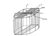
- the hybrid radial method uses a fast spin echo (FSE) method to rotate k-trajectory (trajectory of k-space; blade) obtained at one repetition time (TR) for each TR while rotating k-space. It is a technique to fill. In the hybrid radial method, each blade always fills the center of k-space. There is a technique for correcting body movement by detecting rotation and parallel movement of a subject using this overlapping portion (see Non-Patent Document 3, for example).
- FSE fast spin echo
- Non-Patent Document 3 the correction image generated from the overlapping portion of the k space used for body motion detection is usually lower than the spatial resolution of the diagnostic image used for diagnosis. For this reason, a feature point such as a structure may not be detected in the correction image. In particular, at the slice position where the cross section is substantially circular, such as the top of the head, even when the subject is not actually moving, the body motion of the subject may be erroneously detected, and an incorrect correction image may be generated.
- the present invention has been made in view of the above circumstances, and an object of the present invention is to provide a technique that realizes stable body motion correction at high speed in multi-slice imaging using a non-orthogonal sampling method in which overlapping portions occur in k-space.
- the present invention detects a subject's body movement (rotation and translation) for each specific region (blade in the case of the hybrid radial method) using a slice in which the most characteristic features appear in the imaging region, and the specific region is detected in all slices. Used for region body motion correction.
- the slice used for correction may be determined using a mathematical analysis result such as correlation. Data collection and correction processing may be performed in parallel.
- a magnetic resonance imaging apparatus that obtains an image of each slice of a subject based on magnetic resonance signals respectively measured from a plurality of slices of the subject placed in a static magnetic field
- a data collection unit that collects magnetic resonance signals corresponding to each specific area as specific area data by rotating a specific area including the origin and the vicinity of the origin around the origin, and correcting the specific area data after correction
- a data correction unit that generates specific area data and an image reconstruction unit that reconstructs an image from the specific area data after correction, and the data correction unit uses one slice among a plurality of slices as a reference slice,
- the body movement of the subject that occurs between the measurement of the reference specific area as a reference in the plurality of specific areas and the measurement of the specific area other than the reference specific area is detected in the reference slice and detected.
- the specific area data of the other specific area is corrected in all slices so that the influence of the body movement on the image is eliminated, and the specific area data of the reference specific area and the corrected area of the other specific area are corrected in each slice.
- a magnetic resonance imaging apparatus characterized in that specific area data is used as corrected specific area data.
- a magnetic resonance imaging method for obtaining an image of each slice of a subject based on magnetic resonance signals respectively measured from a plurality of slices of the subject arranged in a static magnetic field, wherein the k-space origin and the A data collection step for collecting a magnetic resonance signal corresponding to each specific area as specific area data by rotating a specific area including the vicinity of the origin around the origin, and generating corrected data by correcting the specific area data
- a data correction step and an image reconstruction step for reconstructing an image from the corrected data.
- the data correction step includes a reference specific region as a reference in a plurality of specific regions in a reference slice as a reference.
- a magnetic resonance imaging method comprising: a correction step of correcting data of another specific region for all slices using the correction information for each other specific region.
- an MRI apparatus capable of stable body motion correction in multi-slice imaging using a non-orthogonal sampling method in which overlapping portions occur in the k space.
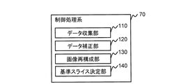
- Block diagram of the MRI apparatus of the first embodiment Functional block diagram of the control processing system of the first embodiment Pulse sequence diagram of hybrid radial method Explanatory diagram for explaining k-space in hybrid radial method in symmetric FOV
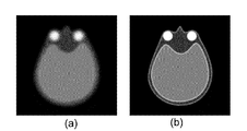
- (a) is an image reconstructed from the overlap part data of echo signals collected by the hybrid radial method
- (b) is an explanatory diagram for explaining an image reconstructed from all blade data
- Explanatory drawing for demonstrating the flow of the conventional correction process Explanatory drawing for explaining the details of body movement correction The figure for demonstrating the flow of the correction process of 1st embodiment.
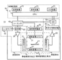
- FIG. 1 is a block diagram showing the overall configuration of the MRI apparatus 10 of the present embodiment.
- the MRI apparatus 10 of the present embodiment obtains a tomographic image of the subject 11 using the NMR phenomenon, and as shown in FIG. 1, a static magnetic field generation system 20, a gradient magnetic field generation system 30, and a transmission system 50 A receiving system 60, a control processing system 70, and a sequencer 40.
- the static magnetic field generation system 20 generates a uniform static magnetic field in the direction perpendicular to the body axis in the space around the subject 11 if the vertical magnetic field method is used, and in the direction of the body axis if the horizontal magnetic field method is used.
- the apparatus includes a permanent magnet type, normal conducting type or superconducting type static magnetic field generating source arranged around the subject 11.
- the gradient magnetic field generation system 30 includes a gradient magnetic field coil 31 wound in the X-axis, Y-axis, and Z-axis directions that are the coordinate system (stationary coordinate system) of the MRI apparatus 10, and a gradient magnetic field power source that drives each gradient magnetic field coil 32, and by driving the gradient magnetic field power supply 32 of each gradient coil 31 in accordance with a command from a sequencer 40 described later, gradient magnetic fields Gx, Gy, Gz in the three axis directions of X, Y, and Z are obtained. Apply.
- the transmission system 50 irradiates the subject 11 with a high-frequency magnetic field pulse (hereinafter referred to as “RF pulse”) in order to cause nuclear magnetic resonance to occur in the nuclear spins of the atoms constituting the living tissue of the subject 11.
- RF pulse high-frequency magnetic field pulse
- the high frequency oscillator 52 generates an RF pulse and outputs it at a timing according to a command from the sequencer 40.
- the modulator 53 amplitude-modulates the output RF pulse, and the high-frequency amplifier 54 amplifies the amplitude-modulated RF pulse and supplies the amplified RF pulse to the transmission coil 51 disposed in the vicinity of the subject 11.
- the transmission coil 51 irradiates the subject 11 with the supplied RF pulse.
- the receiving system 60 detects a nuclear magnetic resonance signal (echo signal, NMR signal) emitted by nuclear magnetic resonance of the nuclear spin constituting the living tissue of the subject 11, and receives a high-frequency coil (receiving coil) on the receiving side. 61, a signal amplifier 62, a quadrature detector 63, and an AD converter 64.
- the reception coil 61 is disposed in the vicinity of the subject 11 and detects an NMR signal of the response of the subject 11 induced by the electromagnetic wave irradiated from the transmission coil 51.
- the detected NMR signal is amplified by the signal amplifier 62, and then divided into two orthogonal signals by the quadrature phase detector 63 at a timing according to a command from the sequencer 40, and each is converted into a digital quantity by the AD converter 64. It is converted and sent to the control processing system 70.
- the sequencer 40 repeatedly applies an RF pulse and a gradient magnetic field pulse according to a predetermined pulse sequence.
- the pulse sequence describes the high-frequency magnetic field, the gradient magnetic field, the timing and intensity of signal reception, and is stored in the control processing system 70 in advance.
- the sequencer 40 operates in accordance with instructions from the control processing system 70, and transmits various commands necessary for collecting tomographic image data of the subject 11 to the transmission system 5, the gradient magnetic field generation system 30, and the reception system 60.
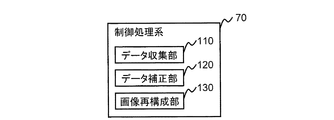
- the control processing system 70 controls the entire MRI apparatus 10, performs various data processing, displays and stores processing results, and includes a CPU 71, a storage device 72, a display device 73, and an input device 74.
- the storage device 72 includes a hard disk and an external storage device such as an optical disk or a magnetic disk.
- the display device 73 is a display device such as a CRT or a liquid crystal.
- the input device 74 is an interface for inputting various control information of the MRI apparatus 10 and control information of processing performed in the control processing system 70, and includes, for example, a trackball or a mouse and a keyboard.
- the input device 74 is disposed in the vicinity of the display device 73. The operator interactively inputs instructions and data necessary for various processes of the MRI apparatus 10 through the input device 74 while looking at the display device 73.
- the CPU 71 executes each program of the control processing system 70 such as control of the operation of the MRI apparatus 10 and various data processing by executing a program stored in advance in the storage device 72 in accordance with an instruction input by the operator. .
- the CPU 71 executes processing such as signal processing and image reconstruction, and a tomogram of the subject 11 as a result is displayed on the display device 73.
- the information is displayed and stored in the storage device 72.
- the transmission coil 51 and the gradient magnetic field coil 31 are opposed to the subject 11 in the static magnetic field space of the static magnetic field generation system 20 in which the subject 11 is inserted, if the vertical magnetic field method is used, and if the horizontal magnetic field method is used. It is installed so as to surround the subject 11. Further, the receiving coil 61 is installed so as to face or surround the subject 11.
- the radionuclide subject to radiography of the MRI apparatus which is widely used in clinical practice, is a hydrogen nucleus (proton) that is the main constituent material of the subject 11.
- the information on the spatial distribution of proton density and the spatial distribution of the relaxation time of the excited state is imaged, so that the form or function of the human head, abdomen, limbs, etc. can be expressed two-dimensionally or three-dimensionally. Take a picture.
- Non-Cartesian sampling methods include, for example, a radial sampling method and a hybrid radial method. And spiral method.
- the hybrid radial method is a combination of the radial method and phase encoding. Specifically, blades (specific areas) that have multiple parallel loci in k-space are rotated around the origin of k-space, that is, each blade is at a different angle in k-space to correspond to each blade
- the echo signal to be measured is measured as blade data (specific area data).
- blade data specific area data
- a plurality of echo signals are acquired for each rotation angle, and multiple echo signals are acquired for each rotation angle ( In other words, all echo signals necessary for image reconstruction are acquired repeatedly for each blade).
- the hybrid radial method since the low spatial frequency region of the k space is measured in an overlapping manner, the fluctuation of the signal due to the body motion can be extracted using this overlapping portion, and the body motion can be corrected.
- the spiral method performs sampling in a spiral shape while changing the rotation angle and the rotation radius with the rotation point and the rotation radius as the center of rotation about one point in k-space (generally the origin), and obtains an echo signal necessary for one image reconstruction.
- the spiral method is applied as a high-speed imaging method because it uses less time when filling the k-space and data can be collected efficiently.
- the gradient magnetic field pulse waveform used when reading the echo signal is not a trapezoidal wave, but a combination of a sine wave and a cosine wave. There are few features. Since this spiral method can also measure the low spatial frequency region of the k-space, it is possible to extract signal fluctuations due to body movement and to correct body movement.
- sampling is performed using these non-orthogonal sampling methods, and the amount of fluctuation due to body motion is extracted using data obtained by overlapping measurement in the low spatial frequency region of k-space, and body motion correction is performed.
- both the hybrid radial method and the spiral method can be applied.
- the case where the hybrid radial method is used will be described as an example.
- the data collection unit 110 samples the k-space for each of the plurality of slices by the hybrid radial method and collects echo signals (multi-slice imaging).
- the collected echo signals are arranged in the k space prepared for each blade and each slice.
- the echo signal arranged in the blade area of the k space is referred to as blade data.
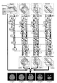
- FIG. 3 shows an example of a pulse sequence 200 of the SE-based hybrid radial method executed by the data collection unit 110 of the present embodiment when collecting blade data.
- RF, Gs, Gp, Gf, AD, and Echo represent axes of an RF pulse, a slice gradient magnetic field, a first readout gradient magnetic field, a second readout gradient magnetic field, AD conversion, and an echo signal, respectively.
- a slice selective gradient magnetic field pulse 211 is applied together with an excitation RF pulse 201 that applies a high-frequency magnetic field to spins in the imaging plane.
- an excitation RF pulse 201 that applies a high-frequency magnetic field to spins in the imaging plane.
- a read dephase in which the phase of the spin is dispersed in advance to generate a slice rephase pulse 212 for returning the phase of the spin diffused by the slice selective gradient magnetic field pulse 211 and an echo signal.
- a gradient magnetic field pulse 231 is applied.
- an inversion RF pulse 203 for inverting the spin in the slice plane is repeatedly applied.
- a slice selection gradient magnetic field pulse 213, a first readout gradient magnetic field pulse 223, and a second readout gradient magnetic field pulse 233 that select a slice are applied, and the timing of the sampling window 243 is applied.
- the echo signal 253 is collected.
- the k-space region filled with echo signals 253 group collected for each excitation RF pulse 201 is a blade.
- the first readout gradient magnetic field pulse 221 and the second readout gradient magnetic field pulse 232 indicate that the echo signal 253 is changed from ⁇ Ky ′ to Ky when the readout direction and the phase encoding direction in the blade are respectively Kx ′ and Ky ′. 'Controlled to be collected towards.
- this sequence is repeatedly executed while changing the amplitudes of the read dephase gradient magnetic field pulse 231 and the read gradient magnetic field pulses 223 and 233 every time interval 261. Collect all 253 groups of echo signals.
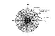
- Figure 4 shows how echo signals collected by this hybrid radial method are arranged in k-space.
- This figure exemplifies a case where the k-space is measured by dividing into 12 blades 310 having different measurement trajectory angles with respect to the coordinate axis (kx-ky) of the k-space.
- FIG. 5 (a) shows an image reconstructed from the data of the overlap section 330
- FIG. 5 (b) shows an image reconstructed from all the data of the blade 310.
- FIG. 4 schematically shows the data arrangement in the k space when the imaging field of view (FOV) is symmetric.
- FOV imaging field of view
- the data correction unit 120 of this embodiment calculates correction information for each blade by using the overlap unit, and corrects the blade data.
- the correction information to be calculated is the amount of body movement of the subject since the measurement of the reference blade.
- the amount of body movement is detected by utilizing the fact that the data (after the gridding process) of the overlap part 330 of each blade has the same k-space coordinate value if there is no body movement.
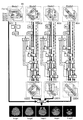
- FIG. 7 is a diagram for explaining a procedure of correction processing for correcting general body movement.
- the case of 5 slices and 4 blades is shown.
- the number of echo signals in each blade is 5.
- each blade data is preliminarily subjected to gridding processing when all the echo signals 253 in the blade are prepared.
- the gridding process may be performed during body motion correction.
- Each slice and blade is given a serial slice number and blade number starting from 1, which uniquely identify the blade and slice.
- a slice with a slice number k is called a slice k
- a blade with a blade number n is called a blade n. That is, 5 slices are slice 1 (Slice 1), slice 2 (Slice 2), slice 3 (Slice 3), slice 4 (Slice 4), slice 5 (Slice 5), 4 blades are blade 1 (Blade 1 ), Blade 2 (Blade2), blade 3 (Blade3), and blade 4 (Blade4).
- blade 1 a blade (reference blade) used as a reference for correction is referred to as blade 1.
- blade 1 blade data (overlap data) in an overlapping area (overlap portion) with other blades is extracted from blade data (BD) 1 for each slice and used as reference data.
- the reference data for each slice is called OD1-1, OD1-2, OD1-3, OD1-4, and OD1-5, respectively.
- the body movement amount (rotation amount and parallel movement amount) of the subject is detected from the reference data and the target data.
- the blade data of the slice is corrected using the detected body motion amount so as to remove the influence of the body motion on the image, and corrected blade data (Corrected Blade Data; CBD) 2 is obtained. Details of the correction information calculation and correction method will be described later.
- blade 3 and blade 4 overlap data is extracted from blade data (BD3, BD4) for each slice, and target data (OD3-1, OD3-2, OD3-3, OD3-4, OD3-5 OD4-1, OD4-2, OD4-3, OD4-4, OD4-5).
- the blade data (BD1) for each slice of blade 1 and the blade data (CBD2, CBD3, CBD4) after correction for each slice of the other blades obtained are combined for each slice, and the combined blade data is obtained.
- reconstruction processing such as Fourier transform is performed for each slice, and reconstructed images (Image1, Image2, Image3, Image4, and Image5) of each slice are obtained.
- the number of blades is 4, the number of echo signals in each blade is 5, and the reference blade is blade 1.
- Body motion correction is generally performed for rotation and parallel movement of the movement (body motion) of the subject that occurs between the measurement of the reference blade and the measurement of other blades. For each blade, the amount of rotation due to rotation and the amount of parallel movement due to parallel movement are detected, and correction is made to remove them.
- the overlap data of the blade 1 is set as reference data (OD1), and the overlap data of other blades is set as target data (OD2, OD3, OD4).
- the rotation correction first, the rotation amount is detected.
- the rotation angle of each target data (OD2, OD3, OD4) based on the reference data (OD1) is calculated using the fact that the rotation in the image space becomes the rotation of the absolute value in the k space as it is.
- the calculated rotation angle is set as the rotation amount of each blade, and the blade data (BD) is corrected so as to cancel this rotation amount.
- parallel movement correction is performed.
- the parallel movement amount is detected.
- the translation amount can be detected as a phase difference of overlap data. Accordingly, the phase difference between the reference data (OD1) and the target data (OD2, OD3, OD4) is calculated and used as the parallel movement amount. Then, the blade data after rotation correction is corrected so as to cancel the obtained phase difference (parallel movement amount), and the corrected blade data (CBD) is obtained.
- the blade data (BD) of blade 1 and the blade data (CBD) after correction of blades 2 to 4 are combined ( Signal synthesis) to create blade data.
- the blade data is Fourier transformed (FFT) to obtain a reconstructed image.
- the data correction unit 120 of the present embodiment uses the body movement amount (rotational movement amount and parallel movement amount) as correction information for each blade between a reference slice of a predetermined reference blade and a reference slice of another blade. To detect. Then, the correction information is applied to all slices for each blade to perform correction.
- body movement amount rotational movement amount and parallel movement amount
- FIG. 9 is a diagram for explaining the flow of the correction processing by the data correction unit 120 and the image reconstruction processing by the image reconstruction unit 130 of the present embodiment.
- FIG. 7 as an example, the case of 5 slices, 4 blades, and 5 echo signals in each blade is shown.
- Each blade data is preliminarily subjected to gridding processing when all the echo signals in the blade are obtained. However, the gridding process may be performed during body motion correction.
- numbers are assigned to the slices and blades.
- a blade (reference blade) used as a reference for correction is referred to as blade 1 (Blade 1).
- the reference slice (reference slice; Benchmark Slice; BS) is slice 3 (Slice3).
- the reference slice (BS) is preferably a slice including a characteristic signal (for example, an eyeball in the case of head imaging) so that rotation and translation can be easily detected.
- the reference slice (BS) is preset by the operator via the input device 74, for example.
- overlap data is extracted from blade data (BD1-3) of slice 3 which is the reference slice and used as reference data (OD1-3).
- blade 2 as in blade 1, overlap data is extracted from the blade data (BD2-3) of the reference slice (slice 3) and used as target data (OD2-3).
- the body movement amount (rotation amount and parallel movement amount) of the blade 2 is calculated.
- the calculated body movement amount is held as correction information 2 (Correction Data 2; CD2) of the blade 2.
- each blade data is corrected using the method described with reference to FIG.
- blade 3 and blade 4 overlap data is extracted from the blade data (BD3-3, BD4-3) of the reference slice and is set as target data (OD3-3, OD4-3), respectively. Then, using the reference data (OD1-3) and target data (OD3-3, OD4-3), correction information 3 (CD3) and correction information 4 (CD4) are calculated, respectively. Using the correction information 3 (CD3) and the correction information 4 (CD4), the blade data (BD3, BD4) of all slices of the blade 3 and the blade 4 are corrected for each slice. Then, corrected blade data (Corrected Blade3 (CBD3), Corrected Blade4 (CBD4)) of each of the blade 3 and the blade 4 is obtained.
- CBD3 Corrected Blade3
- CBD4 Corrected Blade4
- the image reconstruction unit 130 combines the blade data (BD1) of the reference blade and the corrected blade data (CBD2, CBD3, CBD4) for each slice, performs reconstruction processing for each slice, and reconstructs the image. Get (Image1, Image2, Image3, Image4, Image5).
- the operator sets the reference slice used for the correction process.
- the setting is performed using the input device 74 on the positioning image displayed on the display device 73.
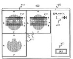
- the reference slice setting screen 400 of the present embodiment configured using the positioning image will be described.
- the number input unit 420 includes a reception unit 421 that receives an input of a slice number, and a determination button 422 that receives an operator's decision to use the slice input to the reception unit 421 as a reference slice.
- the determination button 422 may not be provided independently.
- an imaging start button that receives an instruction to start imaging may also be used.
- the image display unit 410 displays a positioning image (axial image, coronal image, sagittal image) 411 in three directions and a slice position 412 together with a slice number.
- the slice position 412 displays the slice having the number input by the number input unit 420 in an identifiable manner.
- the operator inputs the slice number to the reception unit 421, visually recognizes the slice displayed on the image display unit 410, and determines the reference slice. Alternatively, by selecting the slice displayed on the image display unit 410, the slice number displayed on the reception unit 421 is updated, and the reference slice is determined.
- the data correction unit 120 receives the slice having the number input to the reception unit 421 at the time when the determination button 422 is pressed as a reference slice.
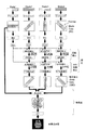
- FIG. 11 (a) is a processing flow for explaining the flow of imaging processing of the present embodiment.
- the number of blades is K and the number of slices is N.
- K and N are integers of 1 or more.
- the data collection unit 110 When receiving an instruction to start imaging, the data collection unit 110 performs data collection processing according to a pulse sequence held in advance (step S1101). Here, the data collection unit 110 collects echo signals for the number of blades K and the number of slices N, and arranges them as blade data in the k space for each slice and each blade.
- the data correction unit 120 performs data correction processing on blade data of blades other than the reference blade, and obtains corrected blade data (step S1102). Details of the data correction processing will be described later.
- the image reconstruction unit 130 performs image reconstruction processing (step S1103).
- the blade data of the reference blade and the blade data after correction of other blades are combined for each slice, and an image is reconstructed for each slice from the combined data.
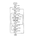
- FIG. 11B is a processing flow of data correction processing of the present embodiment.
- k and n are a blade number counter and a slice number counter, respectively.
- the slice number of the reference slice is bs.
- the data correction unit 120 first creates reference data for the standard slice bs in the standard blade (blade 1 in this embodiment). Specifically, the blade number k of the blade to be processed is set to 1 (step S1201). Then, the overlap data of the standard slice bs is extracted to create reference data (OD1-bs) (step S1202). The reference data OD1-bs is held in the storage device 72 of the control processing system 70.
- the data correction unit 120 acquires correction information for each blade for blades other than the reference blade, corrects the blade data, and generates corrected blade data.
- the blade number k of the blade to be processed is set to 2 (step S1203), and it is determined whether the processing of all the blades has been completed (step S1204).
- the data correction unit 120 performs a correction information acquisition process for acquiring the correction information k of the blade k (step S1205). Details of the correction information acquisition processing will be described later.
- the data correction unit 120 corrects the blade data of all slices of the blade k with the correction information k.
- the slice number n is set to 1 (step S1206), and body motion correction (step S1208) is repeated using the correction information k (step 1209) until the processing of all slices is completed (step S1207).
- body motion correction corrected blade data is generated and stored for each slice.
- step S1207 When the data correction unit 120 finishes correcting the body motion of all the slices of the blade k (step S1207), the data correction unit 120 performs the processing from step S1204 to step S1209 for the blade with the next blade number (step S1210). Then, the processing from step S1204 to step S1209 for each blade is repeated until the processing of all the blades is completed (step S1204).
- the data correction unit 120 of the present embodiment obtains corrected blade data for blades other than the reference blade.
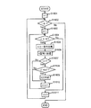
- FIG. 11C is a processing flow of the correction information acquisition process of the present embodiment.
- the reference slice (slice bs) of the blade to be processed (here, blade k) is selected (step S1301). Then, the overlap data is extracted from the blade data (BDk-bs) of the slice bs and set as target data (ODk-bs) (step S1302).
- step S1303 From the reference data (OD1-bs) and the target data (ODk-bs) obtained in step S1203 of the data correction process, the rotation amount and the parallel movement amount are detected by the method described in FIG.
- the correction information (CDk) is set (step S1303).
- the general method shown in FIG. 7 calculates correction information by extracting overlap data and generating reference data or target data N ⁇ K times. Is required (N ⁇ (K-1)) times. However, in this embodiment, it may be K times and (K-1) times, respectively. That is, according to the present embodiment, these processes can be reduced by K ⁇ (N ⁇ 1) times and (N ⁇ 1) ⁇ (K ⁇ 1) times, respectively.
- the number of Fourier transforms can be similarly reduced.
- the amount of body movement used for body movement correction can be detected with high accuracy. Therefore, since other slices are also corrected using the amount of body motion detected with high accuracy, it is possible to perform highly accurate body motion correction as a whole.
- the imaging target is a rigid body such as the head, the body movement (rotation, translation) of the subject hardly changes in any slice. Therefore, this embodiment is effective when the imaging target is such a part.
- highly accurate body motion correction can be performed at high speed. That is, according to the present embodiment, stable body motion correction can be performed at high speed regardless of the structure in the imaging section.
- Second Embodiment a second embodiment to which the present invention is applied will be described.
- This embodiment is basically the same as the first embodiment, but automatically determines a reference slice.
- the present embodiment will be described focusing on the configuration different from the first embodiment.
- FIG. 12 shows a functional block diagram of the control processing system 70 of the present embodiment.
- the control processing system 70 of this embodiment includes a reference slice determination unit 140 in addition to the configuration of the first embodiment.
- the reference slice determination unit 140 determines a reference slice from a plurality of slices.
- the reference slice is preferably a slice including a characteristic signal that is easy to detect rotation and translation. Therefore, in the present embodiment, the reference slice determination unit 140 compares the slice of the reference blade with the rotated image and sets the slice having the lowest correlation as the reference slice.
- details of the reference slice determination process of the reference slice determination unit 140 according to the present embodiment will be described.
- the overlapping part is extracted from the blade data of each slice (Slice 1 to 5) of the reference blade.
- Each extracted overlap data is Fourier transformed to reconstruct a reference image (Reference Image; RI).
- FIG. 13 (a) shows the reconstructed reference images (RI1 to RI5).
- FIG. 13 (b) exemplifies applied images (AI1 to 5) obtained by performing a process of rotating 5 degrees clockwise.
- the predetermined process is not limited to this, and any process may be used as long as it can obtain an applied image that can determine the presence or absence of a feature point of each slice by comparing with a reference image.
- the reference slice determination unit 140 determines a slice having a low similarity between the reference image (RI) and the application image (AI), that is, the lowest correlation value as a reference slice (Benchmark Slice). If the subject 11 moves rigidly, the same rotation and translation should be detected in each slice. A slice having a high correlation processing sensitivity to this movement can be said to be a slice that expresses the influence of these body movements with high sensitivity. Therefore, in this embodiment, in order to stabilize the correction, a slice having a high correlation processing sensitivity, that is, a slice having the largest correlation value fluctuation range and the lowest correlation value is selected and determined as a reference slice.
- FIG. 14 is a process flow for explaining the data correction process of the imaging process of the present embodiment.
- the data collection unit 110 performs data collection processing (step S1401), and acquires blade data (BD) for each blade and slice.
- the reference slice determination unit 140 performs reference slice determination processing for determining a reference slice by the above method using the blade data of each slice of the reference blade (step S1402).
- the data correction unit 120 performs data correction processing on blade data (BD) of blades other than the reference blade using the reference slice determined in step S1402, and obtains corrected blade data (CBD) (step S1402). S1403).
- the image reconstruction unit 130 performs image reconstruction processing (step S1404). Note that the data correction process and the correction information acquisition process of this embodiment are the same as those of the first embodiment.
- the best slice is automatically selected as the reference slice. Since correction is performed by calculating the amount of body movement using the reference slice, the accuracy of correction is improved. Therefore, according to this embodiment, the correction is further stabilized.
- the reference slice determination unit 140 determines a slice that expresses the influence of body motion with high sensitivity based on the correlation with the applied image, but the reference slice determination method is not limited to this.
- the distribution of pixel values of the reference image itself may be calculated, and the slice with the largest variance of pixel values may be determined as the reference slice.
- the configuration of the MRI apparatus 10 of the present embodiment is basically the same as that of the first embodiment.
- the functional configuration of the control processing system 70 of the present embodiment is also the same.
- the CPU 71 of the control processing system 70 performs control so that the data collection processing by the data collection unit 110 and the correction processing by the data correction unit 120 are performed in parallel.
- the timing of each processing when performing data collection and correction processing in parallel during multi-slice imaging by the conventional hybrid radial method using FIG. Will be explained.
- the number of blades is K and the number of slices is N.
- correction processing is sequentially started every time data collection for each slice is completed.
- the reference blade is blade 1.
- echo signals are measured in order from the blade 1 and sequentially from the slice 1 on each slice. At this time, every time measurement of all the echo signals of one slice n of the blade k is finished, each echo signal is arranged in the k space as blade data (BDk-n).
- the blade data (BD) of the reference blade and the blade data (CBD) after correction of other blades are combined to reconstruct the image.
- T acq is the average time required to measure all echo signals of one slice of one blade
- T od is the average time required to create one reference data or target data (referred to as OD creation processing).
- the body motion amount is calculated from the data and the target data, and the average time required for the body motion amount detection correction process for correcting the blade data is T cor
- the time (TotalTime) required from the start of measurement to the end of the correction process is expressed by the following equation (3). Here, it differs depending on the magnitude of the average time T acq required for measuring all echo signals of one slice of one blade and the total time required for OD creation processing and correction processing (T od + T cor ).
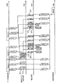
- the timing of each of the data collection process, the data correction process, and the image reconstruction process at the time of multi-slice imaging by the hybrid radial method of the present embodiment will be described with reference to FIG.
- the number of blades is K and the number of slices is N.
- the reference slice (bs-th slice) is determined in advance.
- the data collection unit 110 performs measurement in order from blade 1 to blade K and from slice 1 to slice N, respectively, and the obtained echo signal is used as blade data (BDk-n) for each blade. Place in slice k-space (data collection process).
- the data correction unit 120 extracts overlap data when the blade data (BD1-bs) of the slice bs of the blade 1 is arranged in the k space. Thus, reference data (OD1-bs) is created (reference data creation processing 511).
- the data correction unit 120 determines that the blade data (BDk-bs) of the slice bs of the blade k (k is an integer of 2 or more and K or less) is the k When arranged in the space, overlap data is extracted to create target data (ODk-bs) (target data creation processing 512). Then, correction information (CDk) is created from the reference data (OD1-bs) and the target data (ODk-bs) (correction information creation processing 513).
- the data correction unit 120 converts the blade data (BDk-n) into the correction information (CDk-n) in the order in which the data collection processing is performed on the slices for which the data collection processing for the blade k has been completed. ) To generate blade data (CBDk-n) after correction (correction processing 514).
- the image reconstruction unit 130 performs blade data (BD1-n) of blade 1 and blade data after correction of other blades for each slice. (CBDk-n) and the image for each slice are reconstructed (reconstruction processing).
- the time required for the processing of this embodiment performed in the above procedure is as follows. If the average time required for correction information calculation processing for calculating correction information is T cd , and the average time required for correction processing for correcting each blade data using the correction information is T app , T cd , T app and T cor In the meantime, the following relational expression (4) holds.
- T c is expressed by the following equation using T cd and T app and T cor (5).
- FIG. 17 is a process flow for explaining the flow of the OD creation process of the present embodiment.
- echo signals are collected for each slice.
- the number of slices is N
- the number of echo signals acquired in each slice is I
- the slice number of the reference slice is bs.
- the data acquisition unit 110 acquires echo signals for one slice in order from the slice 1 according to a pulse sequence held in advance, and arranges each in the k space.
- the data correction unit 120 determines whether the slice is a reference slice, and if it is a reference slice, the reference data or the reference data (OD) Create
- the data collection unit 110 assigns 1 to the slice number counter n (step S1501), and determines whether n is N or less (step S1502). Then, 1 is assigned to the echo number counter i (step S1503), and it is determined whether i is equal to or less than I (step S1504). If it is greater than I, the process is terminated.
- step S1505 the data collection unit 110 collects the i-th echo signal (step S1505) and places it in the k space (step S1506). Then, i is incremented by 1 (step S1507), and the process proceeds to step S1504.
- step S1504 When the data collection unit 110 finishes arranging all echo signals of slice n in the k-space of the slice (step S1504), the data correction unit 120 determines whether n is bs (step S1508). If n is bs, the data correction unit 120 creates an OD (step S1509). Then, n is incremented by 1 (step S1510), and the process returns to step S1502. On the other hand, if n is not bs in step S1508, the process proceeds to step S1510.
- the data collection unit 110 and the data correction unit 120 repeat the processing from step S1502 to step S1510 for all slices.
- FIG. 18 is a processing flow for explaining another flow of the OD creation processing of the present embodiment.
- echo signals of all slices are collected for each phase encoding amount.
- the number of slices is N
- the number of echo signals acquired in each slice is I.
- the slice number of the reference slice is bs.
- an OD is created at the timing when all echo signals of the reference slice are collected.
- the data collection unit 110 sets the echo number counter i to 1 (step S1601), and determines whether i is smaller than I (i is equal to I or not) (step S1602).
- the data collection unit 110 sets the slice number counter n to 1 when i is equal to or less than I (step S1603), and determines whether n is equal to or less than N (step S1604). If n is N or less, the i-th echo signal of the n-th slice is collected (step S1605) and arranged in the k space (step S1606).
- the data collection unit 110 determines whether the collected echo signal is the last one in the slice. That is, it is determined whether i is equal to I (step S1607). If it is the last one, the data collection unit 110 determines whether or not the slice is a reference slice. That is, it is determined whether n is equal to bs (step S1608).
- the data correction unit When it is determined that the data collection unit 110 has acquired the last echo signal of the reference slice, the data correction unit creates an OD (step S1609). In other cases, the data collection unit moves to the next slice (step S1610), and repeats the processing from step S1604 to step S1610 until the collection of all echo signals is completed (step S1611). As described above, according to the present embodiment, body motion correction can be performed in parallel with data collection, so that the processing speed can be increased.
- the reference slice is predetermined as an example.
- the reference slice is automatically determined. It is also possible to apply this technique.
- the timing of each process in that case will be described with reference to FIG. As in FIG. 16, the number of blades is K and the number of slices is N.
- the data collection unit 110 performs measurement in order from blade 1 to blade K and from slice 1 to slice N, respectively, and the obtained echo signal is used as blade data (BDk-n) for each blade. Place in slice k-space (data collection process).
- the reference slice determination unit 140 extracts overlap data for each slice of the blade 1 each time blade data (BD1-n) is obtained and extracts a reference image.
- Reference image generation processing 521 for reconstructing (RI) and application image generation processing 522 for generating an application image (AI) from the reference image are performed.
- the standard slice determination unit 140 When the generation of the reference image and the application image of all slices of blade 1 is completed, the standard slice determination unit 140 performs a correlation process 523 for determining a standard slice from the correlation between the reference image of each slice and the application image (standard). Slice determination processing). Note that each time the reference image and the application image of each slice are obtained, the correlation between both is calculated, and the correlation processing 523 may be configured to perform only selection.
- the data correction unit 120 performs a reference data creation process 524 that creates reference data (OD1-bs) from the blade data of the standard slice bs of the blade 1.
- the data correction unit 120 performs target data creation processing 525 for creating target data (ODk-bs), A correction information generation process 526 is performed to generate correction information (CDk) from the reference data (OD1-bs) and the target data (ODk-bs).
- the data correction unit 120 converts the blade data (BDk-n) into correction information (CDk ) Is used to perform correction processing 527 for generating corrected blade data (CBDk-n).
- the image reconstruction unit 130 performs blade data (BD1-n) of blade 1 and blade data after correction of other blades for each slice. (CBDk-n) and the image for each slice are reconstructed (reconstruction processing).
- the accuracy of correction can be improved by automatically determining the reference slice and calculating the correction information. Further, the processing speed can be increased by performing the data collection processing and the correction processing in parallel.
- imaging is not limited thereto.
- data of a three-dimensional region may be collected by a three-dimensional hybrid radial method.
- kz is a slice encoding direction
- kx and ky are two orthogonal directions in a plane orthogonal to kz.
- sampling by the two-dimensional hybrid radial method in the kx-ky plane is performed for the number of slice encodes in the kz direction.
- the collected data is first subjected to Fourier transform processing in the slice encoding direction (kz direction) to obtain multi-slice blade data.
- the body motion correction process of each of the above embodiments is applied to the data (multi-slice blade data) after the Fourier transform.
- the reference blade is the blade 1, but the reference blade is not limited to this.
- the operator can arbitrarily select it.
- the reference blade may be selected using the slice selection screen 400.
- the case where the hybrid radial method is used as the k-space sampling method is described as an example, but the sampling method is not limited to this. It suffices that a desired region of k-space is sampled in an overlapping manner. Therefore, the spiral method may be used as described above. In the case of the spiral method, the above processing is performed using the data of the overlap region for each interleave instead of the blade of the hybrid radial method.
- the data correction unit 120 is described as being included in the control processing system 70.
- the present invention is not limited to this.
- An external information processing apparatus capable of transmitting / receiving data to / from the MRI apparatus 10 may be provided. The same applies to the reference slice determination unit 140 of the second and third embodiments.
- the calculation of the correction information including the rotation amount and the parallel movement amount is not limited to the above method.
- the overlap data of the reference slice of the reference blade is reconstructed, and templates for detecting rotation and translation are respectively created from the reconstructed image.
- Each is created by changing a predetermined change amount ( ⁇ , ( ⁇ x, ⁇ y)) within the expected movement range of the subject.
- these templates are matched with images reconstructed from the overlap data of the reference slices of other blades, and the rotation amount specified by the template that maximizes the correlation and the rotation amount to which the translation amount is applied respectively. , The amount of parallel movement.
- the MRI apparatus of the present invention is to obtain an image of each slice of the subject based on magnetic resonance signals respectively measured from a plurality of slices of the subject arranged in a static magnetic field,
- a data collection unit that collects magnetic resonance signals corresponding to each specific area as specific area data by rotating a specific area including the origin of the k space and the vicinity of the origin around the origin, and corrects the specific area data
- a data correction unit that generates specific region data after correction and an image reconstruction unit that reconstructs an image from the specific region data after correction.
- the data correction unit uses one slice among a plurality of slices as a reference.
- the movement of the subject generated between the measurement of the reference specific area as a reference in the plurality of specific areas and the measurement of the specific area other than the reference specific area in the reference slice
- the specific area data of the other specific area is corrected in all slices so that the influence of the detected body motion on the image is detected, and the specific area data of the reference specific area and other areas are corrected in each slice. Characterized by the specific area data after correction of a specific area and the corrected specific region data.
- the data correction unit calculates body movement using data of a region where the reference specific region overlaps with another specific region in the reference slice.
- the data correction unit includes a reference slice determination unit that determines a reference slice, and the reference slice determination unit determines a slice having a maximum or minimum predetermined feature amount as a reference slice among all slices.
- the reference slice determination unit correlates an image reconstructed from data of a region where the reference specific region and another specific region overlap among all slices and a test image created by a predetermined method. Is determined as a reference slice.
- the reference slice determination unit selects a slice having the largest variance of the pixel value distribution of the image reconstructed from the data of the overlapping region of the reference specific region and the other specific region among all slices. Decide it as a slice.
- the data correction unit corrects the specific area data each time the data collection unit collects the specific area data.
- the image of each slice is obtained by Fourier transforming three-dimensional volume data in the slice direction.
- a reception unit that receives an instruction of a reference slice from an operator is further provided, and the data correction unit performs correction using the slice received by the reception unit as a reference slice.
- the reception unit includes: an image display area in which positions of the plurality of slices are displayed on the positioning image; and a designation area for designating the slice.
- the slice designated in the designation area is the image display area. Is displayed in an identifiable manner.
- each specific region has a plurality of trajectories parallel to the measurement trajectory passing through the origin.
- the magnetic resonance imaging method of the present invention obtains an image of each slice of the subject based on magnetic resonance signals respectively measured from a plurality of slices of the subject placed in a static magnetic field,
- Correction information for calculating, as correction information, the amount of body movement of the subject that occurs between the measurement of the reference specific area as a reference and the measurement of a specific area other than the reference specific area It comprises a calculation step and a correction step for correcting the data of the other specific region for all slices using the calculated correction information for each other specific region.
- the correction information calculation step is executed every time measurement of the reference slice is finished in each specific region.
- the correction step is executed every time the correction information calculation step calculates the correction information of each specific area.
Abstract
Priority Applications (4)
| Application Number | Priority Date | Filing Date | Title |
|---|---|---|---|
| EP11828868.7A EP2623028A4 (fr) | 2010-09-27 | 2011-09-21 | Dispositif d'imagerie par résonance magnétique et procédé d'imagerie par résonance magnétique |
| JP2012536359A JP5942268B2 (ja) | 2010-09-27 | 2011-09-21 | 磁気共鳴イメージング装置および磁気共鳴イメージング方法 |
| US13/823,232 US9064303B2 (en) | 2010-09-27 | 2011-09-21 | Magnetic resonance imaging apparatus and magnetic resonance imaging method configured to correct specific region data based on benchmark slice |
| CN201180046499.4A CN103124516B (zh) | 2010-09-27 | 2011-09-21 | 磁共振成像装置以及磁共振成像方法 |
Applications Claiming Priority (2)
| Application Number | Priority Date | Filing Date | Title |
|---|---|---|---|
| JP2010-215335 | 2010-09-27 | ||
| JP2010215335 | 2010-09-27 |
Publications (1)
| Publication Number | Publication Date |
|---|---|
| WO2012043311A1 true WO2012043311A1 (fr) | 2012-04-05 |
Family
ID=45892773
Family Applications (1)
| Application Number | Title | Priority Date | Filing Date |
|---|---|---|---|
| PCT/JP2011/071410 WO2012043311A1 (fr) | 2010-09-27 | 2011-09-21 | Dispositif d'imagerie par résonance magnétique et procédé d'imagerie par résonance magnétique |
Country Status (5)
| Country | Link |
|---|---|
| US (1) | US9064303B2 (fr) |
| EP (1) | EP2623028A4 (fr) |
| JP (1) | JP5942268B2 (fr) |
| CN (1) | CN103124516B (fr) |
| WO (1) | WO2012043311A1 (fr) |
Cited By (4)
| Publication number | Priority date | Publication date | Assignee | Title |
|---|---|---|---|---|
| JP2014068734A (ja) * | 2012-09-28 | 2014-04-21 | Ge Medical Systems Global Technology Co Llc | 磁気共鳴装置およびプログラム |
| DE102013205208A1 (de) * | 2013-03-25 | 2014-09-25 | Siemens Aktiengesellschaft | Verfahren zum Bestimmen mehrerer Magnetresonanz-Bilder und Magnetresonanz-Anlage |
| JP2016536045A (ja) * | 2013-10-08 | 2016-11-24 | コーニンクレッカ フィリップス エヌ ヴェKoninklijke Philips N.V. | 補正マルチスライス磁気共鳴イメージング |
| US20220317220A1 (en) * | 2021-03-31 | 2022-10-06 | Siemens Healthcare Gmbh | Method for Reducing Artifacts in Image Data Sets Acquired Using Magnetic Resonance |
Families Citing this family (8)
| Publication number | Priority date | Publication date | Assignee | Title |
|---|---|---|---|---|
| WO2014185323A1 (fr) * | 2013-05-17 | 2014-11-20 | 株式会社 日立メディコ | Appareil et procédé d'imagerie par résonance magnétique |
| US9684979B2 (en) * | 2013-09-30 | 2017-06-20 | Siemens Healthcare Gmbh | MRI 3D cine imaging based on intersecting source and anchor slice data |
| CN104181487B (zh) * | 2013-11-19 | 2015-07-01 | 上海联影医疗科技有限公司 | K空间重建方法及装置 |
| US20180267124A1 (en) * | 2015-02-06 | 2018-09-20 | Hitachi, Ltd. | Magnetic resonance imaging apparatus and magnetic resonance imaging method |
| DE102016207641A1 (de) | 2016-05-03 | 2017-11-09 | Siemens Healthcare Gmbh | Parallele Magnetresonanz-Akquisitionstechnik |
| EP3748385A1 (fr) * | 2019-06-04 | 2020-12-09 | Koninklijke Philips N.V. | Commande de profil d'espace k optimisée pour imagerie par résonance magnétique radiale ou spirale 3d |
| CN110680321B (zh) * | 2019-09-26 | 2023-08-29 | 东软医疗系统股份有限公司 | 脊柱mri扫描参数的确定方法、装置及图像处理设备 |
| CN111551881B (zh) * | 2020-05-12 | 2022-05-03 | 山东省肿瘤防治研究院(山东省肿瘤医院) | 基于粒子加速器的核磁共振磁场测量方法及系统 |
Citations (5)
| Publication number | Priority date | Publication date | Assignee | Title |
|---|---|---|---|---|
| WO2005023108A1 (fr) * | 2003-09-05 | 2005-03-17 | Hitachi Medical Corporation | Appareil d'imagerie par resonance magnetique |
| WO2006077715A1 (fr) * | 2005-01-20 | 2006-07-27 | Hitachi Medical Corporation | Appareil d’imagerie à résonance magnétique |
| JP2008178592A (ja) * | 2007-01-25 | 2008-08-07 | Ge Medical Systems Global Technology Co Llc | 磁気共鳴イメージング装置、スキャン装置、磁気共鳴イメージング方法、および、そのプログラム |
| WO2009093517A1 (fr) * | 2008-01-23 | 2009-07-30 | Hitachi Medical Corporation | Imageur à résonance magnétique et procédé d'acquisition d'images multi-contrastes |
| JP2010524622A (ja) * | 2007-04-27 | 2010-07-22 | コーニンクレッカ フィリップス エレクトロニクス エヌ ヴィ | プロペラmri用磁気共鳴装置及び方法 |
Family Cites Families (18)
| Publication number | Priority date | Publication date | Assignee | Title |
|---|---|---|---|---|
| JP3162444B2 (ja) * | 1991-11-28 | 2001-04-25 | 株式会社東芝 | 磁気共鳴診断装置 |
| US5946425A (en) * | 1996-06-03 | 1999-08-31 | Massachusetts Institute Of Technology | Method and apparatus for automatic alingment of volumetric images containing common subject matter |
| JP4060459B2 (ja) * | 1998-05-27 | 2008-03-12 | 株式会社日立メディコ | 磁気共鳴イメージング装置 |
| GB0109892D0 (en) * | 2001-04-20 | 2001-06-13 | Secr Defence | Method and apparatus for reducing the effects of motion in an image |
| US6496560B1 (en) * | 2001-11-21 | 2002-12-17 | Koninklijke Philips Electronics, N.V. | Motion correction for perfusion measurements |
| US6512807B1 (en) * | 2001-11-21 | 2003-01-28 | Koninklijke Philips Electronics, N.V. | Low signal correction for perfusion measurements |
| US6745066B1 (en) * | 2001-11-21 | 2004-06-01 | Koninklijke Philips Electronics, N.V. | Measurements with CT perfusion |
| JP4341312B2 (ja) * | 2003-06-30 | 2009-10-07 | 東レ株式会社 | ポリエチレングリコール含有共重合体 |
| US7945305B2 (en) * | 2005-04-14 | 2011-05-17 | The Board Of Trustees Of The University Of Illinois | Adaptive acquisition and reconstruction of dynamic MR images |
| JP5179182B2 (ja) * | 2005-07-27 | 2013-04-10 | 株式会社日立メディコ | 磁気共鳴イメージング装置 |
| US7408345B2 (en) * | 2006-02-06 | 2008-08-05 | The Board Of Trustees Of The Leland Stanford Junior University | Generalized MRI reconstruction with correction for multiple image distortion |
| US7423430B1 (en) * | 2007-04-06 | 2008-09-09 | The Board Of Trustees Of The University Of Illinois | Adaptive parallel acquisition and reconstruction of dynamic MR images |
| JP5399240B2 (ja) * | 2007-06-14 | 2014-01-29 | 株式会社日立メディコ | 磁気共鳴イメージング装置及び傾斜磁場に起因する誤差補正方法 |
| DE102007028660B3 (de) * | 2007-06-21 | 2009-01-29 | Siemens Ag | Verfahren zur Korrektur von Bewegungsartefakten bei der Aufnahme von MR-Bildern |
| WO2009051123A1 (fr) * | 2007-10-18 | 2009-04-23 | Hitachi Medical Corporation | Dispositif d'imagerie par résonance magnétique |
| JP5575385B2 (ja) * | 2007-11-02 | 2014-08-20 | 株式会社東芝 | 磁気共鳴イメージング装置 |
| US20100215238A1 (en) * | 2009-02-23 | 2010-08-26 | Yingli Lu | Method for Automatic Segmentation of Images |
| US8384383B2 (en) * | 2010-03-23 | 2013-02-26 | Max-Planck-Gesellschaft zur Foerferung der Wissenschaften E.V. | Method and device for reconstructing a sequence of magnetic resonance images |
-
2011
- 2011-09-21 WO PCT/JP2011/071410 patent/WO2012043311A1/fr active Application Filing
- 2011-09-21 US US13/823,232 patent/US9064303B2/en active Active
- 2011-09-21 JP JP2012536359A patent/JP5942268B2/ja active Active
- 2011-09-21 CN CN201180046499.4A patent/CN103124516B/zh active Active
- 2011-09-21 EP EP11828868.7A patent/EP2623028A4/fr not_active Withdrawn
Patent Citations (5)
| Publication number | Priority date | Publication date | Assignee | Title |
|---|---|---|---|---|
| WO2005023108A1 (fr) * | 2003-09-05 | 2005-03-17 | Hitachi Medical Corporation | Appareil d'imagerie par resonance magnetique |
| WO2006077715A1 (fr) * | 2005-01-20 | 2006-07-27 | Hitachi Medical Corporation | Appareil d’imagerie à résonance magnétique |
| JP2008178592A (ja) * | 2007-01-25 | 2008-08-07 | Ge Medical Systems Global Technology Co Llc | 磁気共鳴イメージング装置、スキャン装置、磁気共鳴イメージング方法、および、そのプログラム |
| JP2010524622A (ja) * | 2007-04-27 | 2010-07-22 | コーニンクレッカ フィリップス エレクトロニクス エヌ ヴィ | プロペラmri用磁気共鳴装置及び方法 |
| WO2009093517A1 (fr) * | 2008-01-23 | 2009-07-30 | Hitachi Medical Corporation | Imageur à résonance magnétique et procédé d'acquisition d'images multi-contrastes |
Non-Patent Citations (5)
| Title |
|---|
| G. H. GLOVER; J. M. PAULY: "Projection Reconstruction Techniques for Reduction of Motion Effects in MRI", MAGNETIC RESONANCE IN MEDICINE, vol. 28, 1992, pages 275 - 289, XP000330802 |
| JAMES G. PIPE: "Motion Correction With PROPELLER MRI: Application to Head Motion and Free-Breathing Cardiac Imaging", MAGNETIC RESONANCE IN MEDICINE, vol. 42, 1999, pages 963 - 969, XP055404416, DOI: doi:10.1002/(SICI)1522-2594(199911)42:5<963::AID-MRM17>3.0.CO;2-L |
| JAMES G. PIPE: "Multishot Diffusion-Weighted FSE Using PROPELLER MRI", MAGNETIC RESONANCE IN MEDICINE, vol. 47, 2002, pages 42 - 52, XP003003834, DOI: doi:10.1002/mrm.10014 |
| JAMES G.PIPE: "Periodically Rotated Overlapping ParallEL Lines with Enhanced Reconstruction (PROPELLER) MRI; Application to Motion Correction", PROC. INTL. SOC. MAG. RESON. MED., 24 May 1999 (1999-05-24), XP055081855, Retrieved from the Internet <URL:http://cds.ismrm.org/ismrm-1999/PDF1/242.pdf> * |
| See also references of EP2623028A4 |
Cited By (9)
| Publication number | Priority date | Publication date | Assignee | Title |
|---|---|---|---|---|
| JP2014068734A (ja) * | 2012-09-28 | 2014-04-21 | Ge Medical Systems Global Technology Co Llc | 磁気共鳴装置およびプログラム |
| DE102013205208A1 (de) * | 2013-03-25 | 2014-09-25 | Siemens Aktiengesellschaft | Verfahren zum Bestimmen mehrerer Magnetresonanz-Bilder und Magnetresonanz-Anlage |
| CN104068859A (zh) * | 2013-03-25 | 2014-10-01 | 西门子公司 | 用于确定多个磁共振图像的方法和磁共振设备 |
| JP2014184146A (ja) * | 2013-03-25 | 2014-10-02 | Siemens Aktiengesellschaft | 複数の磁気共鳴画像の決定方法および磁気共鳴装置 |
| DE102013205208B4 (de) * | 2013-03-25 | 2015-02-12 | Siemens Aktiengesellschaft | Multiecho-Magnetresonanz-Messsequenz mit erhöhter Auflösung |
| KR101625733B1 (ko) | 2013-03-25 | 2016-05-30 | 지멘스 악티엔게젤샤프트 | 다수의 자기 공명 이미지를 결정하기 위한 방법 및 자기 공명 시스템 |
| JP2016536045A (ja) * | 2013-10-08 | 2016-11-24 | コーニンクレッカ フィリップス エヌ ヴェKoninklijke Philips N.V. | 補正マルチスライス磁気共鳴イメージング |
| US20220317220A1 (en) * | 2021-03-31 | 2022-10-06 | Siemens Healthcare Gmbh | Method for Reducing Artifacts in Image Data Sets Acquired Using Magnetic Resonance |
| US11747425B2 (en) * | 2021-03-31 | 2023-09-05 | Siemens Healthcare Gmbh | Method for reducing artifacts in image data sets acquired using magnetic resonance |
Also Published As
| Publication number | Publication date |
|---|---|
| JPWO2012043311A1 (ja) | 2014-02-06 |
| JP5942268B2 (ja) | 2016-06-29 |
| US9064303B2 (en) | 2015-06-23 |
| CN103124516A (zh) | 2013-05-29 |
| US20130170727A1 (en) | 2013-07-04 |
| CN103124516B (zh) | 2015-11-25 |
| EP2623028A1 (fr) | 2013-08-07 |
| EP2623028A4 (fr) | 2017-10-25 |
Similar Documents
| Publication | Publication Date | Title |
|---|---|---|
| JP5942268B2 (ja) | 磁気共鳴イメージング装置および磁気共鳴イメージング方法 | |
| EP1911400A1 (fr) | Dispositif d'imagerie par résonance magnétique | |
| JP2014508019A (ja) | 不均一磁場中におけるmriのための撮像領域の制約 | |
| JP6464088B2 (ja) | 磁気共鳴イメージング装置および磁気共鳴イメージング方法 | |
| JP5858791B2 (ja) | 磁気共鳴イメージング装置及び血管画像撮像方法 | |
| JP6117097B2 (ja) | 磁気共鳴イメージング装置、及び再構成画像取得方法 | |
| JP5735916B2 (ja) | 磁気共鳴イメージング装置及び同期計測方法 | |
| US10132902B2 (en) | Intrinsic navigation from velocity-encoding gradients in phase-contrast MRI | |
| JP2018033691A (ja) | 磁気共鳴測定装置および画像処理方法 | |
| JP2008055023A (ja) | 磁気共鳴イメージング装置 | |
| JP6483269B2 (ja) | 磁気共鳴イメージング装置および撮像シーケンス生成方法 | |
| US20170196475A1 (en) | Magnetic resonance imaging apparatus | |
| US20140055137A1 (en) | Magnetic resonance imaging apparatus and echo signal measurement method | |
| JP5942269B2 (ja) | 磁気共鳴イメージング装置および撮像パラメータ適正化方法 | |
| WO2018020964A1 (fr) | Dispositif de diagnostic par imagerie et dispositif d'imagerie par résonance magnétique | |
| JP6230882B2 (ja) | 磁気共鳴イメージング装置及びエコー時間設定方法 | |
| JP2007275481A (ja) | 磁気共鳴イメージング装置 | |
| JP6169909B2 (ja) | 磁気共鳴イメージング装置及び実数成分画像取得方法 | |
| CN115429248A (zh) | 磁共振成像装置以及图像处理装置 | |
| JP2019076182A (ja) | 磁気共鳴イメージング装置 | |
| JP2014200571A (ja) | 磁気共鳴イメージング装置及び2項パルス制御法 | |
| JP2014135992A (ja) | 医用画像診断装置、及び画像処理パラメータ設定方法 |
Legal Events
| Date | Code | Title | Description |
|---|---|---|---|
| WWE | Wipo information: entry into national phase |
Ref document number: 201180046499.4 Country of ref document: CN |
|
| 121 | Ep: the epo has been informed by wipo that ep was designated in this application |
Ref document number: 11828868 Country of ref document: EP Kind code of ref document: A1 |
|
| WWE | Wipo information: entry into national phase |
Ref document number: 2012536359 Country of ref document: JP |
|
| WWE | Wipo information: entry into national phase |
Ref document number: 13823232 Country of ref document: US |
|
| NENP | Non-entry into the national phase |
Ref country code: DE |
|
| WWE | Wipo information: entry into national phase |
Ref document number: 2011828868 Country of ref document: EP |