WO2012042985A1 - 自動製パン器 - Google Patents
自動製パン器 Download PDFInfo
- Publication number
- WO2012042985A1 WO2012042985A1 PCT/JP2011/064105 JP2011064105W WO2012042985A1 WO 2012042985 A1 WO2012042985 A1 WO 2012042985A1 JP 2011064105 W JP2011064105 W JP 2011064105W WO 2012042985 A1 WO2012042985 A1 WO 2012042985A1
- Authority
- WO
- WIPO (PCT)
- Prior art keywords
- state
- clutch
- unit
- bread
- motor
- Prior art date
- Legal status (The legal status is an assumption and is not a legal conclusion. Google has not performed a legal analysis and makes no representation as to the accuracy of the status listed.)
- Ceased
Links
Images







Classifications
-
- A—HUMAN NECESSITIES
- A21—BAKING; EDIBLE DOUGHS
- A21B—BAKERS' OVENS; MACHINES OR EQUIPMENT FOR BAKING
- A21B7/00—Baking plants
- A21B7/005—Baking plants in combination with mixing or kneading devices
Definitions
- the present invention relates to an automatic bread maker mainly used in general households.
- an automatic bread maker for home use generally has a mechanism for producing bread by directly using a bread container into which bread ingredients are placed (see, for example, Patent Document 1).
- a bread container in which bread ingredients are placed is placed in a baking chamber in the main body.
- the bread raw material in a bread container is kneaded into bread dough with the kneading blade provided in a bread container (kneading process).
- a fermentation process for fermenting the kneaded bread dough is performed, and the bread container is used as a baking mold to bake the bread (baking process).
- this bread manufacturing method first, cereal grains and liquid are mixed, and the crushed blade is rotated in this mixture to pulverize the cereal grains (grinding step). And the bread raw material containing the paste-form ground powder obtained through the grinding process is kneaded into bread dough using a kneading blade (kneading process). Thereafter, a fermentation process for fermenting the kneaded bread dough is performed, followed by a baking process for baking the bread.
- an automatic bread maker that can produce bread using cereal grains as a starting material includes a motor for crushing used in the crushing process and a kneading machine used in the kneading process. It is considered preferable to employ a configuration in which the motor is separately provided.
- Such an automatic bread maker with two motors is unprecedented, and there is a new mechanism for manufacturing bread by reliably switching the transmission state of the rotational power generated by driving each motor according to the process. Desired.
- an object of the present invention is to provide an automatic bread maker that can reliably switch the transmission state of rotational power generated by driving a motor according to the process.
- the automatic bread maker of the present invention is a first breadth capable of rotating at a low speed to a driving shaft that can be connected to a bread container into which bread ingredients are charged so that the rotational power can be transmitted.
- a state selection unit that selectively realizes each of the second state in which the rotational power of the second motor is allowed to be applied to the driving shaft, and whether the first state or the first state.
- a state detection unit that detects whether the state is 2 and a control unit that controls the state selection unit so as to correspond to each step included in the manufacturing process. Is started, the detection result of the state detection unit Be sure.
- the control unit checks the detection result of the state detection unit when the process is started. Therefore, it is possible to prevent the automatic bread maker from being damaged or being unable to execute the process as expected by rotating the driving shaft in a state not corresponding to the process.
- the control unit confirms the detection result of the state detection unit when restarting the stopped manufacturing process and at least one of when shifting from the previous process to the next process. May be.
- the state realized by the state selection unit may be indeterminate, the state realized by the state selection unit may be switched to an unexpected state, or the state realized by the state selection unit
- the control unit checks the detection result of the state detection unit when starting a process that particularly requires confirmation of the state because there is a possibility that it has not been switched to the expected one. Therefore, it is possible to effectively prevent the automatic bread maker from being damaged or being unable to execute the process as expected by rotating the driving shaft in a state that does not correspond to the process. Become.
- the control unit checks a detection result of the state detection unit when restarting the stopped manufacturing process, thereby corresponding to a process started by resuming the manufacturing process. It may be confirmed whether or not the state is realized. According to this configuration, the control unit confirms the detection result of the state detection unit when an operation that requires confirmation of the state because the state realized by the state selection unit is uncertain is appropriate. It becomes possible to obtain the state.
- the control unit moves from the previous step to the next step, the state corresponding to the previous step and the state corresponding to the next step are the same. Then, it is good also as confirming whether the state corresponding to the said following process is implement
- the control unit It is possible to confirm the detection result and obtain an appropriate state.
- the control unit moves from the previous step to the next step, the state corresponding to the previous step is different from the state corresponding to the next step. If so, after the state selection unit is controlled to switch between the first state and the second state, the detection result of the state detection unit is confirmed, so that the next step It is good also as confirming whether the state corresponding to is realized. According to this configuration, when starting a process that requires confirmation of the state because there is a possibility that the state realized by the state selection unit is not switched to the expected state, the control unit It is possible to confirm the detection result and obtain an appropriate state.
- the control unit when the control unit confirms that a state corresponding to a predetermined process to be started is not realized by confirming a detection result of the state detection unit, the state selection is performed. May be controlled to try to switch between the first state and the second state. According to this configuration, when the state selection unit does not realize the expected state, the control unit attempts to switch the state selection unit. Therefore, it is possible to increase the possibility that the state selection unit will be in the expected state, and to increase the possibility that the control unit will complete the manufacturing process.
- the control unit controls the state selection unit to try switching between the first state and the second state, and then detects the state detection unit.
- the state selection unit is further Control and try to switch between the first state and the second state, and if the number of switching attempts so far is greater than or equal to a predetermined number, do not try further switching Also good.
- the control unit ends the trial when the expected state is not realized even after a predetermined number of attempts to switch the state selection unit. Therefore, it is possible to suppress waiting in vain.
- the control unit controls driving of the first motor and the second motor, and in one step, the first motor and the second motor.
- One of the motors can be driven
- the state selection unit includes a clutch in which power transmission and power interruption are controlled by the control unit, and when the clutch performs power transmission, the first selection unit A first power transmission unit that connects the output shaft of the motor and the driving shaft so as to be able to transmit power, and a second power transmission unit that connects the output shaft of the second motor and the driving shaft so as to be able to transmit power.
- the state where the clutch performs power transmission may be a first state
- the state where the clutch performs power cutoff may be a second state.
- the configuration of the automatic bread maker can be simplified.
- the second motor that can apply high-speed rotation power to the driving shaft drives not only the driving shaft but also the first motor that can apply low-speed rotation power to the driving shaft.
- the second motor may be damaged due to a large load.
- a control part checks the detection result of a state detection part when a process is started, it becomes possible to suppress that such a situation arises.
- the control unit checks the transmission state of the rotational power generated by driving the motor when the process is started. Therefore, the transmission state of the rotational power generated by driving the motor can be switched reliably according to the process.
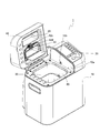
- the schematic perspective view which shows the external appearance structure of the automatic bread maker of this embodiment The schematic diagram for demonstrating the structure inside the main body of the automatic bread maker of this embodiment.
- the figure for demonstrating the clutch contained in the 1st power transmission part with which the automatic bread maker of this embodiment is provided, and the figure which shows the state in which a clutch cuts off power The figure for demonstrating the clutch contained in the 1st power transmission part with which the automatic bread maker of this embodiment is provided, and the figure which shows the state in which a clutch transmits power
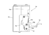
- the schematic solenoid figure which shows the solenoid for clutches with which the automatic bread maker of this embodiment is equipped, and its periphery The figure which shows the state which has an arm part in a lower position Schematic side view of the configuration shown in FIG.
- FIG. 4A Schematic side view of the configuration shown in FIG. 4B
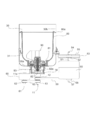
- the figure which shows typically the structure of the baking chamber in which the bread container was accommodated, and its periphery in the automatic bread maker of this embodiment.
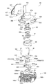
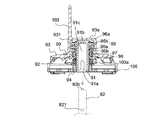
- the schematic perspective view which shows the structure of the blade unit with which the automatic bread maker of this embodiment is provided.
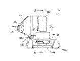
- the schematic side view which shows the structure of the blade unit with which the automatic bread maker of this embodiment is provided. Sectional view taken along the line AA in FIG. 9A
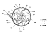
- FIG. 2 is a schematic plan view of the blade unit provided in the automatic bread maker according to the present embodiment when viewed from below, and a view when the kneading blade is in a folded posture.
- FIG. 2 is a schematic plan view of the blade unit provided in the automatic bread maker according to the present embodiment when viewed from below, and a view when the kneading blade is in a folded posture.
- FIG 3 is a schematic plan view of the blade unit provided in the automatic bread maker according to the present embodiment when viewed from below, and a diagram when the kneading blade is in an open posture.
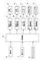
- the block diagram which shows the structure of the automatic bread maker of this embodiment The schematic diagram which shows the flow of the bread-making course for rice grains performed with the automatic bread maker of this embodiment
- FIG. 1 is a schematic perspective view showing an external configuration of the automatic bread maker according to the present embodiment.
- an operation unit 20 is provided on a part of the upper surface of a main body 10 (the outer shell of which is formed of, for example, metal or synthetic resin) of an automatic bread maker 1 provided in a substantially rectangular parallelepiped shape. It has been.
- the operation unit 20 includes an operation key group and a display unit that displays time, contents set by the operation key group, errors, and the like.
- the operation key group includes, for example, a start key, a cancel key, a timer key, a reservation key, a bread manufacturing course (a course for manufacturing bread using rice grains as a starting material, a course for manufacturing bread using rice flour as a starting material) And a selection key for selecting a course for producing bread using flour as a starting material.
- the display unit is configured by, for example, a liquid crystal display panel.
- the firing chamber 30 is composed of, for example, a bottom wall 30a made of sheet metal and four side walls 30b (see also FIG. 6 described later).
- the baking chamber 30 has a substantially rectangular box shape in plan view, and its upper surface is open.
- the firing chamber 30 can be opened and closed by a lid 40 provided on the upper part of the main body 10.
- the lid 40 is attached to the back side of the main body 10 with a hinge shaft (not shown), and the firing chamber 30 can be opened and closed by rotating about the hinge shaft as a fulcrum.
- FIG. 1 shows a state where the lid 40 is opened.
- the lid 40 is provided with a viewing window 41 made of heat-resistant glass, for example, so that the inside of the baking chamber 30 can be seen.
- a bread ingredient storage container 42 is attached to the lid 40. This bread ingredient storage container 42 makes it possible to automatically feed some bread ingredients during the bread production process.
- the bread raw material storage container 42 includes a box-shaped container body 42a having a substantially rectangular plane shape, and a container lid 42b that is provided so as to be rotatable with respect to the container body 42a and opens and closes the opening of the container body 42a. .
- the bread ingredient storage container 42 can support the container lid 42b from the outer surface (lower surface) side and maintain the closed state of the opening of the container body 42a, and is moved by an external force to move the container lid 42b to the container lid 42b. There is also provided a movable hook 42c for releasing the engagement.
- An automatic closing solenoid 16 (see FIG. 12 to be described later) is provided in the main body 10 on the lower side of the operation unit 20, and when the automatic closing solenoid is driven, the plunger is adjacent to the lid 40. It protrudes from an opening 10b provided in 10a. Then, the movable hook 42c is moved by a movable member (not shown) movable by the protruding plunger, the engagement between the container lid 42b and the movable hook 42c is released, the container lid 42b is rotated, and the container main body 42a. The opening of is opened. Note that FIG. 1 shows a state where the opening of the container main body 42a is opened.
- the container main body 42a and the container lid 42b are preferably provided with a metal such as aluminum so that powder bread materials (for example, gluten, dry yeast, etc.) stored in the container do not remain in the container. These surfaces are preferably covered with a coating layer such as silicon or fluorine, and more preferably configured to be covered with an alumite layer. Moreover, it is preferable that the container main body 42a and the container lid 42b are formed as smoothly as possible without being uneven. The same applies to the members on the inner side of the lid 40 (the side on which the bread ingredient storage container 42 is attached), and it is preferable that the base is made of aluminum and the surface is covered with a coating layer such as silicon or fluorine or an alumite layer. .
- a flange is provided at the opening side edge of the container main body 42a so that the aforementioned steam or the like does not enter the container, and a packing is provided between the flange and the container lid 42b. (Seal member) 42d is interposed.
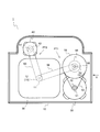
- FIG. 2 is a schematic diagram for explaining the internal configuration of the main body of the automatic bread maker according to the present embodiment.
- FIG. 2 assumes a case where the automatic bread maker 1 is viewed from above, and the lower side of the figure is the front side of the automatic bread maker 1 and the upper side of the figure is the back side.
- a low-speed / high-torque type kneading motor 50 used in the kneading process is fixedly disposed on the right side of the baking chamber 30, and the grinding process is performed behind the baking chamber 30.
- the high-speed rotation type crushing motor 60 used in the above is fixedly arranged.
- the kneading motor 50 and the crushing motor 60 are both shafts.
- the kneading motor 50 is an example of the first motor of the present invention
- the crushing motor 60 is an example of the second motor of the present invention.
- the first pulley 52 is fixed to the output shaft 51 protruding from the upper surface of the kneading motor 50.
- the first pulley 52 is connected by a first belt 53 to a second pulley 55 having a diameter larger than that of the first pulley 52 and fixed to the upper side of the first rotating shaft 54.
- a second rotating shaft 57 is provided on the lower side of the first rotating shaft 54 so that the center of rotation is substantially the same as the first rotating shaft 54 (see FIGS. 3A and 3B described later).
- the first rotating shaft 54 and the second rotating shaft 57 are rotatably supported inside the main body 10.
- a clutch 56 (an example of the clutch of the present invention) that performs power transmission and power interruption is provided between the first rotating shaft 54 and the second rotating shaft 57 (FIG. 3A and FIG. 3B). The configuration of the clutch 56 will be described later.
- a third pulley 58 is fixed to the lower side of the second rotating shaft 57 (see FIGS. 3A and 3B described later).
- the third pulley 58 is provided on the lower side of the firing chamber 30 by the second belt 59 and is fixed to the driving shaft 11 and has a first driving shaft pulley 12 (having substantially the same diameter as the third pulley 58). (See FIGS. 3A and 3B described later).
- the kneading motor 50 itself is a low speed / high torque type, and the rotation of the first pulley 52 is decelerated and rotated by the second pulley 55 (for example, decelerated to 1/5 speed). For this reason, when the kneading motor 50 is driven in a state where the clutch 56 transmits power, the driving shaft 11 rotates at a low speed.
- the power transmission unit composed of the first driving shaft pulley 12 is an example of the first power transmission unit of the present invention.
- this power transmission unit may be expressed as the first power transmission unit PT1.
- a fourth pulley 62 is fixed to the output shaft 61 protruding from the lower surface of the grinding motor 60.
- the fourth pulley 62 is fixed by a third belt 63 below the second driving shaft pulley 13 (below the first driving shaft pulley 12) fixed to the driving shaft 11; 3A and FIG. 3B).
- the second driving shaft pulley 13 has substantially the same diameter as the fourth pulley 62.
- the power transmission unit including the fourth pulley 62, the third belt 63, and the second driving shaft pulley 13 is an example of the second power transmission unit of the present invention.
- this power transmission unit may be expressed as a second power transmission unit PT2.
- the second power transmission unit PT2 has a configuration that does not have a clutch, and connects the output shaft 61 of the crushing motor 60 and the driving shaft 11 so that power can be transmitted constantly.
- the configuration in which the first power transmission unit PT1 and the second power transmission unit PT2 are combined is an example of the state selection unit of the present invention.
- 3A and 3B are views for explaining a clutch included in the first power transmission unit provided in the automatic bread maker of the present embodiment.
- 3A and 3B are diagrams assuming a case of viewing along the direction of the arrow X in FIG. 3A shows a state where the clutch 56 performs power cut-off, and FIG. 3B shows a state where the clutch 56 performs power transmission.
- the clutch 56 includes a first clutch member 561 and a second clutch member 562. Then, when the claw 561a provided on the first clutch member 561 and the claw 562a provided on the second clutch member 562 are engaged with each other (the state shown in FIG. 3B), the clutch 56 transmits power. Further, when the two claws 561a and 562a are not engaged with each other (the state shown in FIG. 3A), the clutch 56 cuts off the power. That is, the clutch 56 is a meshing clutch.
- each of the two clutch members 561 and 562 has a circumferential direction (when the first clutch member 561 is seen in plan view from below, or the second clutch member 562 is seen in plan view from above. Assuming the case), six claws 561a and 562a arranged at almost equal intervals are provided, but the number of the claws may be appropriately changed. Moreover, what is necessary is just to select a preferable shape suitably for the shape of nail
- the first clutch member 561 is slidable in the axial direction (vertical direction in FIGS. 3A and 3B) with respect to the first rotating shaft 54 and is not relatively rotatable. It is attached.
- a spring 71 is loosely fitted on the upper side of the first clutch member 561 of the first rotating shaft 54.
- the spring 71 is disposed so as to be sandwiched between a stopper portion 54a provided on the first rotating shaft 54 and the first clutch member 561, and biases the first clutch member 561 downward.
- the second clutch member 562 is fixed to the upper end of the second rotating shaft 57.
- Switching between the power transmission state and the power cut-off state in the clutch 56 is performed using the arm portion 72 that can be selectively arranged at the lower position (first position) and the upper position (second position). A part of the arm portion 72 is disposed below the first clutch member 561 and can contact the outer peripheral portion of the first clutch member 561.
- the first clutch member 561 moves downward while being pushed by the urging force of the spring 71.
- the first clutch member 561 and the second clutch member 562 are engaged with each other. That is, when the arm portion 72 is in the lower position, the clutch 56 transmits power.
- the automatic bread maker 1 includes the clutch 56 that performs power transmission and power interruption in the first power transmission unit PT1.
- the second power transmission unit PT2 is not provided with a clutch, for the following reason. That is, even if the kneading motor 50 is driven, the driving shaft 11 is only rotated at a low speed (for example, 180 rpm). For this reason, even if the rotational power for rotating the driving shaft 11 is transmitted to the output shaft of the crushing motor 60, a large load is not applied to the kneading motor 50. And the manufacturing cost of the automatic bread maker 1 is suppressed by adopting the structure in which the clutch is not provided in the second power transmission part PT2 in this way. However, it goes without saying that a configuration in which a clutch is provided in the second power transmission unit PT2 may be adopted.
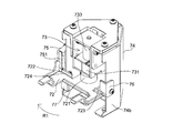
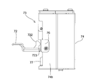
- FIG. 4A and FIG. 4B are schematic perspective views showing the configuration of a solenoid for a clutch provided in the automatic bread maker of the present embodiment and its periphery.
- 4A shows a state where the arm portion 72 is in the upper position (the same state as FIG. 3A)
- FIG. 4B shows a state where the arm portion 72 is in the lower position (the same state as FIG. 3B).
- 5A is a schematic side view of the configuration shown in FIG. 4A
- FIG. 5B is a schematic side view of the configuration shown in FIG. 4B. 4A and 4B, and FIGS. 5A and 5B have different viewing directions.
- the arm 72 is driven using a clutch solenoid.
- the clutch solenoid 73 is supported by a support portion 74.
- the clutch solenoid 73 includes a permanent magnet 731 and is a so-called self-holding solenoid.
- the plunger 732 of the clutch solenoid 73 is fixed to the plunger fixing attachment portion 721 of the arm portion 72. For this reason, the arm portion 72 moves in accordance with the movement of the plunger 732 whose amount of protrusion from the housing 733 varies due to the application of voltage.
- the clutch solenoid 73 is a self-holding solenoid, but this is merely an example. That is, the clutch solenoid 73 may be of a type that does not include the permanent magnet 731.
- a micro switch 75 is fixedly arranged on the outer surface side of the one side wall 74a of the support portion 74 that supports the clutch solenoid 73.
- the switch part 751 of the microswitch 75 is switched on and off according to a pressing state by a switch pressing part 722 provided integrally (bently formed) on the arm part 72. Specifically, when the arm unit 72 is in the upper position, the switch unit 751 is most pressed by the switch pressing unit 722 and is turned on. On the other hand, when the arm portion 72 is in the lower position, the switch portion 751 is not pressed (contacted) by the switch pressing portion 722 and is turned off.
- the switch part 751 of the microswitch 75 is switched on and off depending on whether or not the clutch 56 is in a state of transmitting power. That is, the micro switch 75 detects whether the clutch 56 is in a state of transmitting power or in a state of cutting off power.
- the micro switch 75 is an example of a state detection unit of the present invention.
- the control device 120 checks the state (ON or OFF) of the microswitch 75 at a predetermined timing, and controls the state of the clutch 56.
- the pulverization motor 60 may be damaged as described above (the pulverization motor 60 is rotated at a high speed despite the clutch 56 being in a state of transmitting power), or as expected. The situation where the operation is not performed does not occur. Details of the confirmation operation of the micro switch 75 by the control device 120 will be described later.
- a first guide portion 76 is fixedly disposed on the side wall 74b of the support portion 74 that faces the side wall 74a on which the microswitch 75 is provided.
- the first guide portion 76 is substantially L-shaped when viewed from above. Of the two parts constituting the L-shape, the first side is fixed to the side wall 74 b in a state where the one side is substantially parallel to the side wall 74 b of the support part 74, and the other protrudes toward the inside of the support part 74.
- One guide portion 76 is attached to the support portion 74.
- the arm portion 72 is provided with a first contact portion 723 that can contact a part of the first guide portion 76 (the portion protruding toward the inside of the support portion 74 described above).
- the first contact portion 723 is integrally provided on the arm portion 72 by bending. When the arm portion 72 is in the lower position, the first contact portion 723 does not contact the first guide portion 76 (see FIG. 4B). In the middle of the movement of the arm portion 72 from the lower position to the upper position, the first contact portion 723 contacts the first guide portion 76. Thereafter, the first contact portion 723 is pressed from the first guide portion 76 while being slid with respect to the first guide portion 76 until the arm portion 72 reaches the upper position (the pressing direction). (Left direction in FIG. 5A). An inclined surface is provided on the lower side of the first guide portion 76 so that the engagement with the first contact portion 723 can be performed smoothly.
- the arm portion 72 has some play in the rotation direction around the plunger 732 (provided in the clutch solenoid 73) due to manufacturing reasons and the like. For this reason, when the first guide portion 76 presses the first contact portion 723, the arm portion 72 rotates in the R1 direction shown in FIG. 4A.
- the arm portion 72 When there is no first guide portion 76, the arm portion 72 may be moved from the lower position to the upper position while the arm portion 72 is rotated in the opposite direction to the R1 direction due to the above-described play.
- the switch pressing portion 722 cannot sufficiently press the switch portion 751, and the micro switch 75 may erroneously detect that the arm portion 72 is in the lower position even though the arm portion 72 is in the upper position.
- the first guide portion 76 presses the arm portion 72 and the switch pressing portion 722 corrects the direction of the arm portion 72 in a direction approaching the switch portion 751. Sufficient pressing of the switch unit 751 by the pressing unit 722 is obtained, and the above-described erroneous detection is difficult to occur.
- a second guide portion 77 similar to the first guide portion 76 described above is fixedly disposed below the microswitch 75 on the side wall 74a of the support portion 74 where the microswitch 75 is provided.
- the arm portion 72 is provided with a second contact portion 724 that can contact the second guide portion 77.
- the second contact portion 724 is provided integrally with the arm portion 72 by bending.
- the second contact portion 724 When the arm portion 72 is in the upper position, the second contact portion 724 does not contact the second guide portion 77. In the middle of the movement of the arm portion 72 from the upper position to the lower position, the second contact portion 724 contacts the second guide portion 77. Thereafter, the second contact portion 724 is pressed from the second guide portion 77 while being slid with respect to the second guide portion 77 until the arm portion 72 reaches the lower position (the pressing direction). (Right direction in FIG. 5B). An inclined surface is provided on the upper side of the second guide portion 77 so that the engagement with the second contact portion 724 can be performed smoothly.
- the arm part 72 rotates in the R2 direction shown in FIG. 4B.
- the arm part 72 may be moved from the upper position to the lower position in a state where the arm part 72 is rotated in the opposite direction to the R2 direction by the above-described play.
- the micro switch 75 may erroneously detect that the arm portion 72 is in the upper position even though the switch pressing portion 722 is not separated from the switch portion 751 and the arm portion 72 is in the lower position.
- the switch pressing portion 722 may be caught by the switch portion 751 when the arm portion 72 tries to rise from the lower position to the upper position in a state where the arm portion 72 rotates in the direction opposite to the R2 direction.
- the second guide portion 77 presses the arm portion 72 and the switch pressing portion 722 corrects the direction of the arm portion 72 in the direction away from the switch portion 751.
- the pressing part 722 can be sufficiently separated from the switch part 751. For this reason, it is difficult for the above-described erroneous detection and catching to occur.
- the first guide portion 76 and the second guide portion 77 are separate members from the support portion 74, but may be formed integrally with the support portion 74.
- the guide portions 76 and 77 and the arm portion 72 are formed of materials having different hardnesses. This is because if the members that are in a sliding relationship with each other have the same hardness, seizure is likely to occur and the movement of the arm portion 72 may be deteriorated.
- the arm portion 72 is made of metal, and the guide portions 76 and 77 are made of resin.
- a configuration in which two guide members 76 and 77 are provided to correct the orientation of the arm portion 72 is adopted.
- the present invention is not limited to this configuration, and a configuration in which only one of the first guide member 76 and the second guide member 77 is provided may be employed.
- a configuration is adopted in which the switch portion 751 of the microswitch 75 is turned on when the clutch 56 is in a state where the power is cut off.
- the present invention is not limited to this configuration, and it is of course possible to employ a configuration in which the switch unit 751 is turned on when the clutch 56 is in a state of transmitting power.
- a configuration is adopted in which the position of the first clutch member 561 is switched by the movement of the arm portion 72 among the first clutch member 561 and the second clutch member 562 constituting the clutch 56. It was.
- the configuration is not limited to this, and a configuration in which the position of the second clutch member 562 is switched by the movement of the arm portion 72 instead of the first clutch member 561 may be adopted.
- FIG. 6 is a diagram schematically showing a configuration of a baking chamber in which a bread container is accommodated and its surroundings in the automatic bread maker of the present embodiment.
- FIG. 6 assumes a configuration when the automatic bread maker 1 is viewed from the front side, and the configurations of the baking chamber 30 and the bread container 80 are generally shown in cross-sectional views.
- the bread container 80 used as a baking mold while the bread raw material is input can be taken in and out of the baking chamber 30.
- a sheathed heater 31 (an example of a heating unit) is disposed inside the baking chamber 30 so as to surround a bread container 80 accommodated in the baking chamber 30.
- this sheathed heater 31 it is possible to heat the bread ingredients in the bread container 80 (this expression may include bread dough).
- a bread container support portion 14 (for example, made of an aluminum alloy die-cast product) that supports the bread container 80 is fixed to a location that is substantially at the center of the bottom wall 30a of the baking chamber 30.
- the bread container support portion 14 is formed so as to be recessed from the bottom wall 30a of the baking chamber 30, and the shape of the recess is substantially circular when viewed from above.
- the above-described driving shaft 11 is supported so as to be substantially perpendicular to the bottom wall 30a.
- the bread container 80 is, for example, an aluminum alloy die-cast molded product (others may be made of sheet metal or the like), has a bucket-like shape, and is handed to the flange 80a provided on the side edge of the opening. A handle (not shown) is attached.
- the horizontal cross section of the bread container 80 is a rectangle with rounded corners. Further, a concave portion 81 having a substantially circular shape in a plan view is formed on the bottom of the bread container 80 so as to accommodate a part of a blade unit 90 which will be described in detail later.
- a blade rotating shaft 82 extending in the vertical direction is rotatably supported in a state where a countermeasure against sealing is taken.
- a container side coupling member 82a is fixed to the lower end of the blade rotation shaft 82 (projecting outward from the bottom of the bread container 80).
- a cylindrical pedestal 83 is provided on the bottom outer surface side of the bread container 80, and the bread container 80 is accommodated in the baking chamber 30 in a state where the pedestal 83 is received by the bread container support part 14. It has become so.
- the pedestal 83 may be formed separately from the bread container 80 or may be formed integrally with the bread container 80.
- the container-side coupling member 82 a provided at the lower end of the blade rotation shaft 82 and the driving shaft 11.
- the coupling (coupling) with the driving shaft side coupling member 11a fixed to the upper end of the shaft can be obtained.
- the blade rotation shaft 82 can transmit the rotational power from the driving shaft 11.
- FIG. 7 is a schematic perspective view showing a configuration of a blade unit provided in the automatic bread maker of the present embodiment.
- FIG. 8 is a schematic exploded perspective view showing a configuration of a blade unit provided in the automatic bread maker of the present embodiment.
- 9A and 9B are diagrams showing a configuration of a blade unit included in the automatic bread maker of the present embodiment, FIG. 9A is a schematic side view, and FIG. 9B is a cross-sectional view at the position AA in FIG.
- FIG. 10A and 10B are schematic plan views of the blade unit included in the automatic bread maker according to the present embodiment when viewed from below,
- FIG. 10A is a view when the kneading blade is in a folded position
- FIG. 10B is a kneading blade. It is a figure when is in an open posture.
- 10A and 10B show a state in which a guard to be described later is removed.
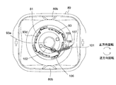
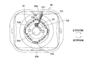
- FIG. 11A and FIG. 11B are diagrams when the bread container provided in the automatic bread maker of the present embodiment is viewed from above.
- FIG. 11A is a view when the kneading blade is in a folded position
- FIG. 11B is a view when the kneading blade is in an open position.
- the blade unit 90 is roughly divided into a unit shaft 91, a crushing blade 92 attached to the unit shaft 91 so as not to rotate relative to the unit shaft 91, and a plan view attached to the unit shaft 91 so as to be relatively rotatable and covering the crushing blade 92.
- the configuration includes a substantially circular dome-shaped cover 93 and a kneading blade 101 attached to the dome-shaped cover 93 so as to be relatively rotatable (see, for example, FIGS. 7, 8, 9A and 9B).
- the crushing blade 92 is positioned slightly above the bottom surface of the recess 81 of the bread container 80. Further, almost the entire grinding blade 92 and the dome-shaped cover 93 are accommodated in the recess 81.
- the unit shaft 91 is a substantially cylindrical member formed of a metal such as a stainless steel plate, for example, and has an opening at one end (the lower end in FIGS. 8 and 9B), and the inside is hollow. That is, the insertion shaft 91c is formed in the unit shaft 91 (see FIG. 9B). Further, a pair of notches 91a are formed on the lower side (opening side) of the side wall of the unit shaft 91 so as to be symmetrically arranged with respect to the rotation center of the unit shaft 91 (see, for example, FIG. 8; however, FIG. 8). 8 shows only one side).
- the upper inner surface of the unit shaft 91 is engaged with the convex portion 82b provided at the center of the upper surface (substantially circular) of the blade rotation shaft 82 (shown by a broken line).
- a recess 91b is formed at the center. Accordingly, the blade unit 90 can be easily attached to the blade rotation shaft 82 in a state where the centers of the unit shaft 91 and the blade rotation shaft 82 are aligned. For this reason, unnecessary rattling during rotation of the blade is suppressed.
- the convex portion 82b is provided on the blade rotating shaft 82 side and the concave portion 91b is provided on the unit shaft 91 side, but conversely, the concave portion is provided on the blade rotating shaft 82 side and the unit shaft 91 side is provided.
- a configuration in which a convex portion is provided may be employed.
- the pulverizing blade 92 for pulverizing grains is formed of, for example, a stainless steel plate, and the shape thereof is, for example, an airplane propeller. As shown in FIG. 8, an opening 923 a having a substantially rectangular shape in plan view is formed at the center of the crushing blade 92. The crushing blade 92 is attached from the lower side of the unit shaft 91 so that the unit shaft 91 is fitted into the opening 923a.
- the lower side of the unit shaft 91 has a shape that is obtained by scraping the side surface of the cylinder, and is substantially the same shape (substantially rectangular shape) as the opening 923a of the grinding blade 92 when viewed from below.
- the area when the lower side of the unit shaft 91 is viewed from below is slightly smaller than the opening 923a. Since such a shape is adopted, the grinding blade 92 is attached to the unit shaft 91 so as not to be relatively rotatable. Since the stopper member 94 for preventing the retaining member 94 is fitted into the unit shaft 91 on the lower side of the pulverizing blade 92, the pulverizing blade 92 does not fall off the unit shaft 91.
- the dome-shaped cover 93 disposed so as to surround and cover the crushing blade 92 is made of, for example, an aluminum alloy die-cast product, and a bearing 95 (in this embodiment, a rolling bearing is used on the inner surface side thereof. ) (See FIG. 9B) is formed.
- the dome-shaped cover 93 has a configuration in which a substantially cylindrical convex portion 93a is formed at the center when viewed from the outer surface.
- the opening is not formed in the convex part 93a, and the bearing 95 accommodated in the accommodating part 931 is in the state in which the side surface and the upper surface are enclosed by the wall surface of the accommodating part 931.
- the inner ring 95a is attached to the unit shaft 91 so as not to rotate relative to the bearing 95 with the retaining rings 96a and 96b arranged on the upper and lower sides (the unit shaft 91 is press-fitted into a through hole inside the inner ring 95a. ing).
- the bearing 95 is press-fitted into the housing portion 931 so that the outer wall of the outer ring 95b is fixed to the side wall of the housing portion 931.
- the dome-shaped cover 93 is attached to the unit shaft 91 so as to be rotatable relative to the bearing 95 (the inner ring 95a rotates relative to the outer ring 95b).
- the housing portion 931 of the dome-shaped cover 93 is made of, for example, a silicon-based material so that foreign matter (for example, liquid used when pulverizing grain grains or paste-like material obtained by pulverization) does not enter the bearing 95 from the outside.
- a seal material 97 formed of a fluorine-based material and a metal seal cover 98 that holds the seal material 97 are press-fitted from the lower side of the bearing 95.
- the seal cover 98 is fixed to the dome-shaped cover 93 with a rivet 99 so that the fixing to the dome-shaped cover 93 is ensured.
- fixing with the rivet 99 may not be performed, it is preferable to configure as in the present embodiment in order to obtain reliable fixing.
- the sealing material 97 and the sealing cover 98 function as sealing means.
- the seal cover 98 is preferably coated by Teflon painting or the like. In particular, it is preferable to use a silver paint because the coating is difficult to peel off and even if it is peeled off, it is difficult to stand out.
- a kneading blade 101 (for example, aluminum) in a planar shape is formed by a support shaft 100 (see FIG. 8) arranged so as to extend in a vertical direction at a location adjacent to the convex portion 93 a. (Made of die-cast alloy product) is attached.
- the kneading blade 101 is attached to the support shaft 100 so as not to be relatively rotatable, and moves together with the support shaft 100 attached to the dome-shaped cover 93 so as to be relatively rotatable. In other words, the kneading blade 101 is attached to the dome-shaped cover 93 so as to be relatively rotatable.
- 9 ⁇ / b> A, 9 ⁇ / b> B, and 9 ⁇ / b> B are provided on one surface near the tip of the kneading blade 101 (assuming a portion that draws the largest circle when the kneading blade 101 is rotated about the support shaft 100).
- a cushioning material 107 is attached.
- the buffer material 107 is provided so as to slightly protrude from the tip of the kneading blade 101 (see, for example, FIG. 10B).
- the buffer material 107 is fixed in a state where the buffer material 107 is sandwiched between one surface of the kneading blade 101 and the fixing plate 108 and obtained by caulking the rivet 109 inserted from the other surface side of the kneading blade 101. ing.
- the number of rivets 109 is two, but it goes without saying that the number is not limited.
- the buffer material 107 is disposed so as not to directly contact the bread container 80 (inner wall) when the kneading blade 101 is in an open posture, which will be described in detail later.
- the buffer material 107 is provided to prevent such damage.
- the surface of the bread container 80 and the kneading blade 101 is coated with fluorine.
- the buffer material 107 of the present embodiment is provided so that the fluorine coating is not peeled off by contact between the kneading blade 101 and the pan container 80.
- the material constituting the cushioning material 107 is preferably a material softer than the coating material so as not to peel off the fluorine coating.
- silicone rubber or TPE Thermoplastic Elastomers
- the buffer material 107 also functions as a soundproofing measure, which will be described later. In the following description, the buffer material 107 may be regarded as a part of the kneading blade 101.
- the complementary kneading blade 102 (for example, made of an aluminum alloy die cast product) is fixedly arranged on the outer surface of the dome-shaped cover 93 so as to be aligned with the kneading blade 101.
- the complementary kneading blade 102 is not necessarily provided, but is preferably provided in order to increase the kneading efficiency in the kneading process of kneading the bread dough.
- the kneading blade 101 rotates about the axis of the support shaft 100 together with the support shaft 100, and has two postures, a folded posture shown in FIGS. 7, 9A, 10A and 11A, and an open posture shown in FIGS. 10B and 11B. Take. In the folded position, the protrusion 101a (see FIG. 8) hanging from the lower edge of the kneading blade 101 contacts the first stopper portion 93b provided on the upper surface (outer surface) of the dome-shaped cover 93. For this reason, the kneading blade 101 cannot further rotate counterclockwise (assuming the case viewed from above) with respect to the dome-shaped cover 93. In this folded position, the tip of the kneading blade 101 protrudes slightly from the dome-shaped cover 93.
- the complementary kneading blade 102 is aligned with the kneading blade 101, and the kneading blade 101 is shaped like a “ ⁇ ”. The size becomes larger.
- a first engagement body 103 a constituting the cover clutch 103 is attached to the unit shaft 91 between the grinding blade 92 and the seal cover 98.
- a substantially rectangular opening 103aa is formed in the first engagement body 103a made of, for example, zinc die casting, and the first rectangular body 103 in the lower side of the unit shaft 91 is fitted into the opening 103aa so that the first The engaging body 103a is attached to the unit shaft 91 so as not to be relatively rotatable.
- the first engaging body 103a is fitted from the lower side of the unit shaft 91 prior to the crushing blade 92, and the stopper member 94 prevents the unit shaft 91 from dropping off together with the crushing blade 92.
- the washer 104 is disposed between the first engagement body 103a and the seal cover 98 in consideration of prevention of deterioration of the first engagement body 103a.
- the washer 104 is not necessarily provided. It does not have to be provided.
- a second engagement body 103b constituting the cover clutch 103 is attached to the lower side of the support shaft 100 to which the kneading blade 101 is attached.
- a substantially rectangular opening 103ba is formed in the second engaging body 103b made of zinc die casting, and the second engaging member is fitted into the opening 103ba by fitting a substantially rectangular portion in plan view on the lower side of the support shaft 100.
- the united body 103b is attached to the support shaft 100 so as not to be relatively rotatable.
- the washer 105 is arranged on the upper side of the second engagement body 103b in consideration of prevention of deterioration of the second engagement body 103b. However, the washer 105 is not necessarily provided.
- the cover clutch 103 composed of the first engagement body 103a and the second engagement body 103b functions as a clutch for switching whether or not to transmit the rotational power of the blade rotation shaft 82 to the dome-shaped cover 93.
- the cover clutch 103 is a rotation direction of the blade rotation shaft 82 when the kneading motor 50 rotates the drive shaft 11 (this rotation direction is referred to as “forward rotation”.
- FIGS. 10A and 10B rotate counterclockwise. 11A and 11B, the rotation power of the blade rotation shaft 82 is transmitted to the dome-shaped cover 93.
- the rotation direction of the blade rotation shaft 82 when the crushing motor 60 rotates the driving shaft 11 this rotation direction is referred to as “reverse rotation”.
- FIGS. 10A and 10B rotate counterclockwise. 11A and 11B
- the engaging portion 103bb of the second engaging body 103b is the engaging portion 103ab of the first engaging body 103a (although there are two in this embodiment). It is an angle that interferes with the rotation trajectory (see FIG. 10A). Therefore, when the blade rotation shaft 82 rotates in the forward direction, the first engagement body 103 a and the second engagement body 103 b are engaged, and the rotational power of the blade rotation shaft 82 is transmitted to the dome-shaped cover 93.
- the engagement portion 103bb of the second engagement body 103b deviates from the rotation trajectory of the engagement portion 103ab of the first engagement body 103a. (See the broken line in FIG. 10B). For this reason, even if the blade rotation shaft 82 rotates, the first engagement body 103a and the second engagement body 103b are not engaged. Accordingly, the rotational power of the blade rotation shaft 82 is not transmitted to the dome-shaped cover 93.
- the dome-shaped cover 93 is formed with a window 93d that communicates the space inside the cover and the space outside the cover.
- the window 93d is arranged at a height equal to or higher than the grinding blade 92.
- a total of four windows 93d are arranged at intervals of 90 °, but other numbers and arrangement intervals can be selected.
- each rib 93e extends obliquely from the vicinity of the center of the dome-shaped cover 93 to the outer peripheral annular wall with respect to the radial direction, and the four ribs 93e form a kind of bowl shape. Moreover, each rib 93e is curving so that the side which faces the bread raw material pressed toward it may become convex.
- a removable guard 106 is attached to the lower surface of the dome-shaped cover 93.
- the guard 106 covers the lower surface of the dome-shaped cover 93 and prevents the user's finger from approaching the grinding blade 92.
- the guard 106 is formed of, for example, an engineering plastic having heat resistance, and can be a molded product such as PPS (polyphenylene sulfide).
- PPS polyphenylene sulfide
- a ring-shaped hub 106 a through which a stopper member 94 fixed to the unit shaft 91 is passed is provided at the center of the guard 106.
- a ring-shaped rim 106b is provided at the periphery of the guard 106.
- the hub 106a and the rim 106b are connected by a plurality of spokes 106c. Between the spokes 106c, there is an opening 106d through which the grain to be crushed by the pulverizing blade 92 is passed.
- the opening 106d has a size that prevents a finger from passing through.
- the guard 106 is shaped like an outer blade of a rotary electric razor, and the grinding blade 92 is shaped like an inner blade.
- a total of four columns 106e are integrally formed at the periphery of the rim 106b at intervals of 90 °.
- a horizontal groove 106ea having one end dead end is formed on a side surface of the pillar 106e facing the center side of the guard 106.
- the guard 106 is attached to the dome-shaped cover 93 by engaging the grooves 106 ea with the projections 93 f formed on the outer periphery of the dome-shaped cover 93 (all four are arranged at intervals of 90 °).
- the groove 106ea and the protrusion 93f are provided so as to constitute a bayonet connection.
- the crushing blade 92 and the kneading blade 101 are incorporated into one unit (blade unit 90), the handling thereof is convenient.
- the user can easily pull out the blade unit 90 from the blade rotating shaft 82, and can easily clean the blade after the bread making operation.
- the pulverizing blade 92 provided in the blade unit 90 is detachably attached to the unit shaft 91, and is easily mass-produced and has excellent maintainability such as blade replacement.
- the bearing 95 is preferably a sealed structure so that the liquid does not enter the bearing 95.
- the sealing means the sealing material 97 and the sealing material 97 and the sealing material only on the inner surface side of the dome-shaped cover 93
- the cover 98 is provided, a structure for sealing the bearing 95 is obtained.
- the automatic bread maker 1 it is possible to suppress an adverse effect on the shape of the baked bread (for example, the bottom surface of the bread is greatly recessed).
- FIG. 12 is a block diagram showing the configuration of the automatic bread maker according to the present embodiment.
- the control operation in the automatic bread maker 1 is performed by the control device 120.
- the control device 120 includes, for example, a microcomputer including a CPU (Central Processing Unit), a ROM (Read Only Memory), a RAM (Random Access Memory), an I / O (input / output) circuit unit, and the like. .
- the control device 120 is preferably disposed at a position that is not easily affected by the heat of the baking chamber 30. Further, the control device 120 is provided with a time measuring function, and temporal control in the bread manufacturing process is possible.
- the control device 120 includes the above-described operation unit 20, the temperature sensor 15 that detects the temperature of the baking chamber 30, the above-described micro switch 75, the kneading motor drive circuit 121, the pulverization motor drive circuit 122, and the heater drive circuit. 123, the first solenoid drive circuit 124, and the second solenoid drive circuit 125 are electrically connected.
- the kneading motor driving circuit 121 is a circuit for controlling the driving of the kneading motor 50 under a command from the control device 120.
- the grinding motor drive circuit 122 is a circuit for controlling the driving of the grinding motor 60 under a command from the control device 120.
- the heater drive circuit 123 is a circuit for controlling the operation of the sheathed heater 31 under a command from the control device 120.
- the first solenoid drive circuit 124 controls the driving of the automatic charging solenoid 16 that is driven in order to automatically supply a part of the bread ingredients in the course of the bread manufacturing process under a command from the control device 120. It is a circuit for.
- the second solenoid drive circuit 125 is a clutch solenoid 73 (see FIGS. 4A and 4B) used when switching the state of the clutch 56 (see FIGS. 3A and 3B) under a command from the control device 120. It is a circuit for controlling the drive of.
- the control device 120 reads a program relating to a bread manufacturing course (breadmaking course) stored in a ROM or the like based on an input signal from the operation unit 20, and a kneading blade by the kneading motor 50 via the kneading motor driving circuit 121.
- the automatic bread maker 1 controls the operation of the movable hook 42c by the automatic closing solenoid 16 via the solenoid driving circuit 124 and the switching control of the clutch 56 by the clutch solenoid 73 via the second solenoid driving circuit 125. Execute bread manufacturing process.
- control device 120 confirms the state of the microswitch (state detection unit) 75 when starting a predetermined process, so that the state of the clutch 56 (whether the power is transmitted or the power is shut off). )
- the control device 120 is an example of a control unit of the present invention. Details of the confirmation operation of the micro switch 75 by the control device 120 will be described later.
- FIG. 13 is a schematic diagram showing the flow of a rice grain bread-making course executed by the automatic bread maker 1. As shown in FIG. 13, in the bread making course for rice grains, the dipping process, the pulverizing process, the resting process, the kneading (kneading) process, the fermentation process, and the baking process are sequentially performed in this order.
- the dipping process, the pulverizing process, the resting process, the kneading (kneading) process, the fermentation process, and the baking process are sequentially performed in this order.
- the user attaches the blade unit 90 to the blade rotation shaft 82 by covering the blade rotation shaft 82 of the bread container 80 with the unit shaft 91. Then, the user weighs rice grains, water, and seasonings (eg, salt, sugar, shortening, etc.) by a predetermined amount and puts them into the bread container 80.
- seasonings eg, salt, sugar, shortening, etc.
- the user weighs the bread ingredients that are automatically input during the bread manufacturing process and puts them in the container body 42a of the bread ingredient storage container 42.
- the container lid 42b is supported by the movable hook 42c so that the opening of the container main body 42a is closed by the container cover 42b.
- the bread raw material accommodated in the bread raw material storage container 42 gluten, dry yeast, etc. are mentioned, for example.
- gluten for example, at least one of flour, thickener (eg, guar gum), and upper fresh powder may be stored in the bread ingredient storage container 42.
- only dry yeast may be stored in the bread raw material storage container 42 without using gluten, wheat flour, thickener, super fresh powder or the like.
- salt, sugar and shortening seasonings such as salt, sugar and shortening are stored in the bread ingredient storage container 42 together with, for example, gluten and dry yeast so as to be automatically introduced during the bread manufacturing process. It may be.
- the bread raw material previously put into the bread container 80 is rice grains and water (in place of mere water, for example, a liquid having a taste component such as soup stock, a liquid containing fruit juice or alcohol, etc.) Become.
- the control apparatus 120 starts control operation
- the dipping process is started by a command from the control device 120.
- the bread raw material previously put in the bread container 80 is set in a stationary state, and the stationary state is maintained for a predetermined time (30 minutes in the present embodiment).
- This dipping process is a process aimed at making the rice grains easy to be pulverized to the core in the subsequent pulverization process by adding water to the rice grains.
- the water absorption rate of rice grains varies depending on the temperature of the water. If the water temperature is high, the water absorption rate increases, and if the water temperature is low, the water absorption rate decreases. For this reason, you may make it fluctuate
- the grinding blade 92 may be rotated at the initial stage of the dipping process, and further, the grinding blade 92 may be intermittently rotated thereafter. If it does in this way, the surface of a rice grain can be damaged, and the liquid absorption efficiency of a rice grain will be improved.
- the dipping process is terminated by the command of the control device 120, and the pulverizing process for pulverizing the rice grains is started.
- the crushing blade 92 is rotated at a high speed (for example, 7000 to 8000 rpm) in a mixture containing rice grains and water.
- the control device 120 controls the crushing motor 60 to rotate the blade rotation shaft 82 in the reverse direction (clockwise rotation in FIGS. 10A and 10B and counterclockwise rotation in FIGS. 11A and 11B).
- the control device 120 drives the clutch solenoid 73 before driving the grinding motor 60 so that the clutch 56 shuts off the power (the state shown in FIG. 3A). Then, when it is confirmed by the information obtained from the micro switch 75 that the clutch 56 is in a state where the power is cut off, the control device 120 starts driving the grinding motor 60. For this reason, the crushing motor 60 is not rotated at high speed while the clutch 56 is transmitting power, and the crushing motor 60 is unlikely to fail.
- the dome-shaped cover 93 also starts to rotate following the rotation of the blade rotation shaft 82.
- the rotation of the cover 93 is immediately blocked (stopped). It is preferable that the pulverizing blade 92 is rotated at a low speed in the initial stage of the pulverization process and then rotated at a high speed.
- the rotation direction of the dome-shaped cover 93 accompanying the rotation of the blade rotation shaft 82 for rotating the grinding blade 92 is the counterclockwise direction in FIGS. 11A and 11B, and the kneading blade 101 has been folded until then (see FIG. 11A).
- the resistance is changed from the mixture containing the rice grains and water to the open posture (posture shown in FIG. 11B).
- the engagement portion 103bb of the second engagement body 103b deviates from the rotation trajectory (see the broken line in FIG. 10B) of the engagement portion 103ab of the first engagement body 103a.
- the cover clutch 103 disconnects the blade rotation shaft 82 from the dome-shaped cover 93.
- a part of the kneading blade 101 in the open position (more precisely, the buffer material 107 provided on the tip side) is formed on the inner wall of the bread container 80 (specifically, the grinding efficiency is improved).
- the rotation of the dome-shaped cover 93 is prevented (stopped) in order to abut against the bowl-shaped convex portion 80b provided on the inner wall of the bread container 80 for improvement.
- the pulverization of the rice grains in the pulverization step is performed in a state in which water is soaked in the rice grains by the previously performed immersion step, so that the rice grains can be easily pulverized to the core.
- the rotation of the pulverizing blade 92 in the pulverization step is intermittent. This intermittent rotation is performed, for example, in a cycle of rotating for 30 seconds and stopping for 5 minutes (a cycle in which the process of rotating the grinding blade 92 is repeated intermittently), and this cycle is repeated 10 times. In the last cycle, the stop for 5 minutes is not performed.
- the rotation of the crushing blade 92 may be continuous rotation, but for the purpose of, for example, preventing the temperature of the raw material in the bread container 80 from becoming too high, it is preferable to perform intermittent rotation.
- the pulverization of the rice grains is performed in the dome-shaped cover 93 that has stopped rotating, and therefore the possibility that the rice grains scatter outside the bread container 80 is low. Further, the rice grains entering the dome-shaped cover 93 from the opening 106d of the guard 106 in the rotation stopped state are sheared between the stationary spoke 106c and the rotating pulverizing blade 92, so that the pulverization can be performed efficiently. Further, the rib 93e provided on the dome-shaped cover 93 suppresses the flow of the mixture containing rice grains and water (flow in the same direction as the rotation of the grinding blade 92), so that the grinding can be performed efficiently.
- the mixture containing the pulverized rice grains and water is guided in the direction of the window 93d by the ribs 93e, and discharged from the window 93d to the outside of the dome-shaped cover 93. Since the rib 93e is curved so that the side facing the mixture pressing toward it is convex, the mixture hardly stays on the surface of the rib 93e and flows smoothly toward the window 93d. Further, instead of the mixture being discharged from the inside of the dome-shaped cover 93, the mixture existing in the space above the concave portion 81 enters the concave portion 81 and passes through the opening portion 106d of the guard 106 from the concave portion 81. Enter the cover 93. Since the pulverization by the pulverization blade 92 is performed while being circulated as described above, the pulverization can be performed efficiently.
- the crushing process is completed in a predetermined time (in this embodiment, 50 minutes).
- the grain size of the pulverized powder may vary depending on the hardness of the rice grains and the environmental conditions.
- the end of the pulverization process may be determined based on the magnitude of the load of the pulverization motor 60 (for example, it can be determined by the control current of the motor).
- the pause process is executed according to a command from the control device 120.
- This pause process is provided as a cooling period during which the temperature of the contents in the bread container 80 raised by the crushing process is lowered.
- the reason for lowering the temperature is that the next kneading step is carried out at a temperature at which the yeast is active (for example, around 30 ° C.).
- the pause process is a predetermined time (30 minutes). However, in some cases, the pause process may be performed until the temperature of the bread container 80 reaches a predetermined temperature.
- the kneading process is started by a command from the control device 120.
- the control device 120 drives the clutch solenoid 73 so that the clutch 56 transmits power (the state shown in FIG. 3B).
- the control device 120 starts driving the kneading motor 50 when it is confirmed from the information obtained from the microswitch 75 that the clutch 56 is in a state of transmitting power.
- the control device 120 controls the kneading motor 50 to rotate the blade rotation shaft 82 in the forward direction (counterclockwise rotation in FIGS. 10A and 10B and clockwise rotation in FIGS. 11A and 11B).
- the grinding blade 92 When the blade rotation shaft 82 is rotated in the forward direction, the grinding blade 92 is also rotated in the forward direction, and the bread ingredients around the grinding blade 92 flow in the forward direction. Accordingly, when the dome-shaped cover 93 moves in the forward direction (clockwise in FIGS. 11A and 11B), the kneading blade 101 receives resistance from the non-flowing bread ingredients and is folded from the open position (see FIG. 11B). The angle is changed to (see FIG. 11A). As a result, the engagement portion 103bb of the second engagement body 103b has an angle that interferes with the rotation path of the engagement portion 103ab of the first engagement body 103a (see the broken line in FIG. 10A).
- the cover clutch 103 connects the blade rotation shaft 82 and the dome-shaped cover 93, and the dome-shaped cover 93 enters a state of being driven in earnest by the blade rotation shaft 82.
- the dome-shaped cover 93 and the kneading blade 101 in the folded position rotate together with the blade rotation shaft 82 in the forward direction.
- the rotation of the blade rotation shaft 82 at the initial stage of the kneading process is preferably intermittent rotation or low speed rotation.
- the complementary kneading blade 102 is arranged on the extension of the kneading blade 101, so that the kneading blade 101 is enlarged and the bread raw material is pressed strongly. It is. For this reason, the dough can be kneaded firmly.
- the rotation of the kneading blade 101 (this term is used as an expression including the complementary kneading blade 102 in the folded position, the same applies hereinafter) is very slow in the initial stage of the kneading process, and the speed is increased stepwise.
- Control is performed by the control device 120.
- the control device 120 drives the automatic charging solenoid 16 so that the movable hook 42c of the bread ingredient storage container 42 supports the container lid 42b. Let go. Thereby, the opening of the container main body 42a is opened, and for example, bread ingredients such as gluten and dry yeast are automatically charged into the bread container 80.
- the bread raw material storage container 42 is provided with a coating layer inside the container body 42a and the container lid 42b to improve slipping, and is devised so that there is no uneven portion inside. Yes. Furthermore, the situation where the bread raw material is caught by the packing 42d is also suppressed by the device for arranging the packing 42d. For this reason, the automatic charging is completed with almost no bread ingredients remaining in the bread ingredient storage container 42.
- the bread ingredients stored in the bread ingredient storage container 42 are charged while the kneading blade 101 is rotating.
- the present invention is not limited to this, and the kneading blade 101 is stopped. You may decide to throw in in the state which is carrying out.
- the bread ingredients stored in the bread ingredient storage container 42 are put into the bread container 80, the bread ingredients are kneaded into a dough connected to one having a predetermined elasticity by the rotation of the kneading blade 101. Go.
- the kneading blade 101 swings the dough and knocks it against the inner wall of the bread container 80, an element of “kneading” is added to the kneading.
- the dome-shaped cover 93 also rotates.
- the rib 93e formed on the dome-shaped cover 93 also rotates, so that the bread material in the dome-shaped cover 93 is quickly discharged from the window 93d and the kneading blade 101 kneads the bread. Assimilate into a lump of material.
- the guard 106 also rotates in the forward direction together with the dome-shaped cover 93.
- the spoke 106c of the guard 106 has a shape in which the center side of the guard 106 precedes and the outer peripheral side of the guard 106 follows when rotating in the forward direction.
- the guard 106 rotates in the forward direction to push the bread ingredients inside and outside the dome-shaped cover 93 outward with the spokes 106c. Thereby, the ratio of the raw material used as a waste after baking bread can be reduced.
- the pillar 106e of the guard 106 has a side surface 106eb (see FIG. 8) that is the front surface in the rotation direction when the guard 106 rotates in the forward direction, and is inclined upward. Bread ingredients are sprung upward on the front surface of the column 106e. For this reason, the ratio of the raw material which becomes waste after baking bread can be reduced.
- a predetermined time (10 minutes in this embodiment) obtained experimentally as a time for obtaining bread dough having a desired elasticity is employed as the time for the kneading process.
- the time of the kneading process is constant, the degree of bread dough may vary depending on the environmental temperature or the like. For this reason, for example, a configuration in which the end point of the kneading process is determined based on the magnitude of the load of the kneading motor 50 (for example, it can be determined by the control current of the motor) may be used.
- ingredients for example, raisins, nuts, cheese, etc.
- the ingredients may be introduced during the kneading process.
- the fermentation process is started by a command from the control device 120.
- the control device 120 controls the sheathed heater 31 to maintain the temperature of the baking chamber 30 at a temperature at which fermentation proceeds (for example, 38 ° C.). Then, the bread dough is left for a predetermined time (in this embodiment, 60 minutes) in an environment in which fermentation proceeds.
- the kneading blade 101 may be rotated to perform degassing or rounding of the dough.
- the firing process is started by a command from the control device 120.
- the control device 120 controls the sheathed heater 31 to increase the temperature of the baking chamber 30 to a temperature suitable for baking (for example, 125 ° C.). Then, the control device 120 performs control so that the bread is baked in a baking environment for a predetermined time (in this embodiment, 50 minutes).
- the end of the firing process is notified to the user by, for example, a display on the liquid crystal display panel of the operation unit 20 or a notification sound.
- the user detects the completion of bread making, the user opens the lid 40 and takes out the bread container 80 to complete the bread production.
- the bread in the bread container 80 can be taken out by, for example, directing the opening of the bread container 80 obliquely downward. Simultaneously with the removal of the bread, the blade unit 90 attached to the blade rotation shaft 82 is also removed from the bread container 80. At the bottom of the bread, burn marks of the kneading blade 101 of the blade unit 90 and the complementary kneading blade 102 (projecting upward from the recess 81 of the bread container 80) remain. However, since the dome-shaped cover 93 and the guard 106 are accommodated in the recess 81, they are prevented from leaving a large burn mark on the bottom of the bread.
- the pulverization blade 92 mainly rotates (high-speed rotation is performed by the rotational power of the pulverization motor 60).
- the kneading blade 101 mainly rotates (low-speed rotation is performed by the rotational power of the kneading motor 50). Therefore, as the manufacturing course progresses, the control device 120 sequentially switches the clutch 56 and sequentially controls the rotation and stop of the kneading motor 50 and the grinding motor 60 according to the steps included in the manufacturing course. There is a need to.
- the manufacturing course is roughly divided into steps as shown in FIG. 13, but in practice it can be divided into finer steps.
- the crushing process includes a plurality of processes for rotating the crushing blade 92.
- a process of rotating the kneading blade 101 may be inserted between these processes. This is to make the grains uniform by diffusing the grains.
- a step of rotating the grinding blade 92 may be inserted before and after the firing step. This is to prevent the blade unit 90 from becoming difficult to remove from the bread container 80 or from being burnt.
- the control device 120 needs to sequentially switch the clutch 56 in accordance with these steps, and to sequentially control the rotation and stop of the kneading motor 50 and the grinding motor 60, respectively.
- the control device 120 checks the state of the clutch 56 when the above process is started.
- the “start of process” includes not only the “start of process” when the control device 120 is proceeding with the manufacturing course without any problem, but also the control apparatus for a manufacturing course stopped due to some factor such as a power failure. “Start of process”, such as when 120 resumes, may also be included.
- Start of process such as when 120 resumes, may also be included.
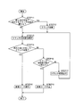
- FIG. 14 is a flowchart showing the operation of checking the clutch state when the manufacturing course is restarted by the control device 120.
- the automatic bread maker 1 of the present embodiment stops the progress of the manufacturing course when the supply of power is stopped, but the power for operating the control device 120 (for example, the power of a built-in button battery or the like). ) Shall be secured.
- the control device 120 waits until a predetermined time (for example, 10 minutes) elapses (STEP 2, NO). At this time, the control device 120 may notify the user that the supply of power to the automatic bread maker 1 is stopped by a display on the liquid crystal display panel of the operation unit 20 or a notification sound. And if the control apparatus 120 confirms that predetermined time passed (STEP2, YES), it will stop the manufacturing course which was stopped and will complete
- a predetermined time for example, 10 minutes
- the controller 120 first confirms the state of the microswitch 75, thereby changing the state of the clutch 56. Confirm (STEP 4). Then, the control device 120 inserts the confirmed state of the clutch 56 into the process at the time of restarting the manufacturing course (for example, the process interrupted because it was executed when power supply was stopped, or the process of restarting the manufacturing course). (Step 5).
- the state of the clutch 56 corresponding to a certain process is a state of the clutch 56 that enables (allows) the operation that the control device 120 is to perform in a certain process.
- the state of the corresponding clutch 56 is power cutoff (the state of FIG. 3A).
- the state of the corresponding clutch 56 is power transmission (state of FIG. 3B).
- the control apparatus 120 restarts the manufacturing course to execute the process at the time of restart (STEP 6).
- the confirmation operation is finished.
- the control device 120 may notify the user that the manufacturing course is resumed by a display on the liquid crystal display panel of the operation unit 20 or a notification sound.
- the controller 120 does not correspond to the process of restarting the confirmed state of the clutch 56 (STEP 5, NO), and the number of attempts to switch the clutch 56 must be X times (for example, 1 time) or more. If this is the case (STEP 7, NO), an attempt is made to switch the clutch 56 (STEP 8). Thereby, the control device 120 tries to make the state of the clutch 56 correspond to the process at the time of restart. Then, after trying to switch the clutch 56, the control device 120 returns to STEP 4 and confirms the state of the clutch 56 again.
- the control device 120 stops the manufacturing course that has been stopped (STEP 3) and ends the confirmation operation. At this time, the control device 120 may notify the user that the manufacturing course has been stopped due to an abnormality in the clutch 56 by a display on the liquid crystal display panel of the operation unit 20 or a notification sound.
- the control device 120 confirms the state of the clutch 56 by performing the confirmation operation as described above when starting a process that particularly requires confirmation of the state because the state of the clutch 56 is indeterminate. Therefore, it is possible to effectively prevent the automatic bread maker 1 from being damaged or being unable to execute the process as expected by rotating the driving shaft 11 in a state not corresponding to the process. It becomes possible.
- control device 120 tries to switch the clutch 56 when the clutch 56 is not in the expected state. Therefore, it is possible to increase the possibility that the clutch 56 will be in the expected state and increase the possibility that the control device 120 will complete the manufacturing course.
- control device 120 terminates the trial if the expected state is not obtained even if the trial of switching the clutch 56 is performed X times or more. Therefore, it is possible to suppress waiting in vain.
- FIG. 15 is a flowchart showing an operation of checking the state of the clutch when the manufacturing course proceeds by the control device 120.
- the control device 120 first responds with the process that was most recently performed (hereinafter referred to as the previous process) and the process that is to be started (hereinafter referred to as the next process). It is confirmed whether or not the state of the clutch 56 to be operated is different (STEP 11). When the state of the corresponding clutch 56 is different between the previous step and the next step (STEP 11, YES), the control device 120 switches the state of the clutch 56 (STEP 12).
- the control device 120 checks the state of the micro switch 75 when the state of the corresponding clutch 56 is the same in the previous step and the next step (STEP 11, NO), or after switching the state of the clutch 56 in STEP 12. Thus, the state of the clutch 56 is confirmed (STEP 13). Then, the control device 120 confirms whether or not the confirmed state of the clutch 56 corresponds to the next step (STEP 14).
- the control device 120 proceeds with the manufacturing course to execute the next step (STEP 15). ), The confirmation operation is finished.
- the controller 120 does not confirm that the state of the clutch 56 corresponds to the next step (STEP 14, NO), and the number of attempts to switch the clutch 56 is not more than Y times (for example, 1 time). (STEP 16, NO), switching of the clutch 56 is tried (STEP 17). Thereby, the control apparatus 120 tries to make the state of the clutch 56 correspond to the next process. Then, after trying to switch the clutch 56, the control device 120 returns to STEP 13 and confirms the state of the clutch 56 again.
- the control device 120 stops the manufacturing course (STEP 18) and ends the confirmation operation. At this time, the control device 120 may notify the user that the manufacturing course has been stopped due to an abnormality in the clutch 56 by a display on the liquid crystal display panel of the operation unit 20 or a notification sound.
- the control device 120 can detect the case where the state of the clutch 56 is switched to an unexpected state or the case where the state of the clutch 56 is not switched to an expected state by performing the confirmation operation as described above. And the control apparatus 120 confirms the state of the clutch 56, when starting the process for which confirmation of a state is especially required. Therefore, it is possible to effectively prevent the automatic bread maker 1 from being damaged or being unable to execute the process as expected by rotating the driving shaft 11 in a state not corresponding to the process. It is possible.
- control device 120 tries to switch the clutch 56 when the clutch 56 is not in the expected state. Therefore, it is possible to increase the possibility that the clutch 56 will be in the expected state and increase the possibility that the control device 120 will complete the manufacturing course.
- control device 120 ends the trial if the expected state is not obtained even if the trial of switching the clutch 56 is performed Y times or more. Therefore, it is possible to suppress waiting in vain.
- the number of times the switching of the clutch 56 is tried regardless of whether the state of the corresponding clutch 56 is the same or different in the previous step and the next step. Although the same Y times are used, the number of times may be different in both cases.
- the control device 120 checks the transmission state of the rotational power generated by driving the kneading motor 50 and the grinding motor 60 when the process is started. Specifically, the control device 120 checks the state of the clutch 56 when the process is started. Thereby, the transmission state of the rotational power generated by driving the kneading motor 50 and the crushing motor 60 can be switched reliably according to the process. Therefore, it is possible to suppress the automatic bread maker 1 from being damaged or being unable to execute the process as expected by rotating the driving shaft 11 in a state not corresponding to the process. .
- the configuration of the automatic bread maker 1 can be simplified.
- the crushing motor 60 that can apply high-speed rotation power to the driving shaft 11 drives not only the driving shaft 11 but also the kneading motor 50 that can apply low-speed rotation power to the driving shaft 11.
- the pulverization motor 60 may be damaged due to a large load.
- the control device 120 checks the state of the clutch 56 when the process is started, it is possible to prevent such a situation from occurring.
- the state of the clutch 56 is detected by the configuration shown in FIGS. 4A, 4B, 5A, and 5B (particularly, the micro switch 75).
- the present invention is not limited to this configuration. That is, any configuration (for example, a configuration using an optical sensor, a magnetic sensor, or the like) may be adopted as long as the configuration of the clutch 56 can be detected.
- the clutch 56 is provided only in the first power transmission unit PT1, but the clutch may be provided in the second power transmission unit PT2.
- the configuration as in the embodiment described above is preferable because the configuration of the automatic bread maker 1 and the processing content of the control device 120 can be simplified.
- the configuration and operation of the automatic bread maker have been described by taking as an example the case where rice grains are used as a starting material.
- the present invention is also applicable when grain grains other than rice grains such as wheat, barley, straw, buckwheat, buckwheat, corn, and soybean are used as starting materials.
- the automatic bread maker 1 of this embodiment uses, for example, cereal flour such as wheat flour and rice flour as a starting raw material. It can also be manufactured. When wheat flour or rice flour is used as a starting material, the grinding blade 92 is not necessary. In this case, a bread container or a blade unit different from those shown above may be used.
- the automatic bread maker 1 which can perform all the processes concerning the manufacture of bread, such as a dough manufacturing process (dipping process, crushing process and kneading process), fermentation process and baking process
- the automatic bread maker of the present invention is not necessarily limited to one capable of executing all these steps.
- those that cannot execute at least one step except the dough manufacturing step can be included in the automatic bread maker of the present invention.
- the configuration related to the process that cannot be executed for example, the sheathed heater 31 and the heater driving circuit 123) may not be provided in the automatic bread maker.
- the present invention is suitable for an automatic bread maker for home use.
Landscapes
- Life Sciences & Earth Sciences (AREA)
- Engineering & Computer Science (AREA)
- Food Science & Technology (AREA)
- Baking, Grill, Roasting (AREA)
Abstract
自動製パン器1は、原動軸11に低速回転させる回転動力を付与可能な第1のモータ50と、原動軸11に高速回転させる回転動力を付与可能な第2のモータ60と、第1のモータ50の回転動力を原動軸11に付与することが許容される第1の状態と第2のモータ60の回転動力を原動軸11に付与することが許容される第2の状態とのそれぞれの状態を選択的に実現する状態選択部と、第1の状態であるか第2の状態であるかを検知する状態検知部75と、を備える。自動製パン器1の制御部120は、製造工程に含まれるそれぞれの工程に対応するように、前記状態選択部を制御するものであり、所定の工程が開始される際に状態検知部75の検知結果を確認する。
Description
本発明は、主として一般家庭で使用される自動製パン器に関する。
市販の家庭用自動製パン器は、パン原料を入れるパン容器をそのまま焼き型としてパンを製造する仕組みのものが一般的である(例えば、特許文献1参照)。このような自動製パン器では、まず、パン原料が入れられたパン容器が本体内の焼成室に入れられる。そして、パン容器内のパン原料がパン容器内に設けられる混練ブレードでパン生地に練り上げられる(練り工程)。その後、練り上げられたパン生地を発酵させる発酵工程が行われ、パン容器が焼き型として使用されてパンが焼き上げられる(焼成工程)。
このような自動製パン器を用いてパンの製造が行われる場合、これまでは、パン原料として、小麦や米などの穀物を製粉した粉(小麦粉、米粉等)や、そのような製粉した粉に各種の補助原料が混ぜられたミックス粉が必要とされた。しかしながら、一般家庭においては、米粒に代表されるように、粉の形態ではなく粒の形態で穀物が所持されることがある。このために、自動製パン器が穀物粒から直接パンを製造する仕組みを有すれば、非常に便利である。このようなことを念頭において、本出願人らは、穀物粒を出発原料としてパンを製造するパンの製造方法を開発している(特許文献2参照)。
このパンの製造方法では、まず、穀物粒と液体とが混合され、この混合物の中で粉砕ブレードが回転されて穀物粒が粉砕される(粉砕工程)。そして、粉砕工程を経て得られたペースト状の粉砕粉を含むパン原料が、混練ブレードを用いてパン生地に練り上げられる(練り工程)。その後、練り上げられたパン生地を発酵させる発酵工程が行われ、続いてパンを焼き上げる焼成工程が行われる。
特許文献2のパンの製造方法では、粉砕ブレードによって穀物粒を粉砕する場合、粉砕ブレードを高速回転(例えば7000~8000rpm)させるのが好ましい。一方、混練ブレードによってパン生地を練り上げる場合、混練ブレードを低速回転(例えば180rpm等)させるのが好ましい。
このため、穀物粒を出発原料としてパンを製造することが可能な自動製パン器の構成としては、粉砕工程の際に使用される粉砕用のモータと、練り工程の際に使用される混練用のモータとが別々に備えられる構成を採用するのが好ましいと考えられる。このような2つのモータを備える自動製パン器はこれまでに類がなく、それぞれのモータの駆動により発生する回転動力の伝達状態を、工程に応じて確実に切り替えてパンを製造する新しい仕組みが求められる。
そこで、本発明の目的は、モータの駆動により発生する回転動力の伝達状態を、工程に応じて確実に切り替え得る自動製パン器を提供することである。
上記目的を達成するために本発明の自動製パン器は、パン原料が投入されるパン容器に回転動力を伝達可能に連結し得る原動軸に、低速回転させる回転動力を付与可能な第1のモータと、前記原動軸に、高速回転させる回転動力を付与可能な第2のモータと、前記第1のモータの回転動力を前記原動軸に付与することが許容される第1の状態と、前記第2のモータの回転動力を前記原動軸に付与することが許容される第2の状態と、のそれぞれの状態を選択的に実現する状態選択部と、前記第1の状態であるか前記第2の状態であるかを検知する状態検知部と、製造工程に含まれるそれぞれの工程に対応するように、前記状態選択部を制御する制御部と、を備え、前記制御部は、所定の工程が開始される際に、前記状態検知部の検知結果を確認する。
本構成によれば、制御部が、工程が開始される際に状態検知部の検知結果を確認する。そのため、工程に対応していない状態で原動軸が回転させられることで自動製パン器が破損したり、工程を期待した通りに実行できなくなったりすることを、抑制することが可能になる。
上記構成の自動製パン器において、前記制御部は、停止した製造工程を再開する際、及び、前の工程から次の工程に移行する際の少なくとも一方で、前記状態検知部の検知結果を確認してもよい。本構成によれば、状態選択部が実現する状態が不確定である、状態選択部が実現する状態が期待しないものに切り替えられている可能性がある、または、状態選択部が実現する状態が期待したものに切り替えられていない可能性がある、などの理由により状態の確認が特に必要となる工程を開始する際に、制御部が状態検知部の検知結果を確認する。そのため、工程に対応していない状態で原動軸が回転させられることで自動製パン器が破損したり、工程を期待した通りに実行できなくなったりすることを、効果的に抑制することが可能になる。
上記構成の自動製パン器において、前記制御部は、停止した製造工程を再開する際に、前記状態検知部の検知結果を確認することで、当該製造工程の再開により開始される工程に対応する状態が実現されているか否かを確認してもよい。本構成によれば、状態選択部が実現する状態が不確定であるために状態の確認が特に必要となる工程を開始する際に、制御部が状態検知部の検知結果を確認して適切な状態を得ることが可能になる。
上記構成の自動製パン器において、前記制御部は、前の工程から次の工程に移行する際に、当該前の工程に対応する状態と、当該次の工程に対応する状態と、が同じものであれば、前記状態検知部の検知結果を確認することで、当該次の工程に対応する状態が実現されているか否かを確認することとしてもよい。本構成によれば、状態選択部が実現する状態が期待しないものに切り替えられている可能性があるために状態の確認が特に必要となる工程を開始する際に、制御部が状態検知部の検知結果を確認して適切な状態を得ることが可能になる。
上記構成の自動製パン器において、前記制御部は、前の工程から次の工程に移行する際に、当該前の工程に対応する状態と、当該次の工程に対応する状態と、が異なるものであれば、前記状態選択部を制御して前記第1の状態と前記第2の状態との間の切替を行った後に、前記状態検知部の検知結果を確認することで、当該次の工程に対応する状態が実現されているか否かを確認することとしてもよい。本構成によれば、状態選択部が実現する状態が期待したものに切り替えられていない可能性があるために状態の確認が特に必要となる工程を開始する際に、制御部が状態検知部の検知結果を確認して適切な状態を得ることが可能になる。
上記構成の自動製パン器において、前記制御部は、前記状態検知部の検知結果を確認することで、開始される所定の工程に対応する状態が実現されていないことを確認すると、前記状態選択部を制御して、前記第1の状態と前記第2の状態との間の切替を試行してもよい。本構成によれば、状態選択部が期待した状態を実現していない場合に、制御部が状態選択部の切替を試行する。そのため、状態選択部が期待した状態になる可能性を高めるとともに、制御部が製造工程を完遂する可能性を高めることができる。
上記構成の自動製パン器において、前記制御部は、前記状態選択部を制御して、前記第1の状態と前記第2の状態との間の切替を試行した後、前記状態検知部の検知結果を確認することで、開始される所定の工程に対応する状態が実現されていないことを確認する場合、それまでに切替を試行した回数が所定の回数より少なければ、さらに前記状態選択部を制御して、前記第1の状態と前記第2の状態との間の切替を試行し、それまでに切替を試行した回数が所定の回数以上であれば、それ以上の切替を試行しないこととしてもよい。本構成によれば、制御部は、状態選択部の切替の試行を所定の回数以上しても期待した状態が実現されないときに、試行を終了する。そのため、無駄に待機することを、抑制することが可能になる。
上記構成の自動製パン器において、前記制御部は、前記第1のモータ及び前記第2のモータの駆動を制御するものであるとともに、1つの工程で、前記第1のモータ及び前記第2のモータのいずれか一方を駆動し得るものであり、前記状態選択部は、動力伝達及び動力遮断が前記制御部によって制御されるクラッチを含み、前記クラッチが動力伝達を行う場合に、前記第1のモータの出力軸と前記原動軸とを動力伝達可能に連結する第1の動力伝達部と、前記第2のモータの出力軸と前記原動軸とを動力伝達可能に連結する第2の動力伝達部と、を備え、前記クラッチが動力伝達を行う状態が第1の状態であり、前記クラッチが動力遮断を行う状態が第2の状態であることとしてもよい。本構成によれば、第1の動力伝達部にのみクラッチを備えるだけで済むため、自動製パン器の構成を簡略化することが可能になる。このような構成にすると、高速回転の動力を原動軸に付与し得る第2のモータが、原動軸だけでなく、原動軸に低速回転の動力を付与し得る第1のモータまで駆動することで、第2のモータに大きな負荷がかかり破損することが懸念される。しかし、制御部は、工程が開始される際に状態検知部の検知結果を確認するため、このような事態が生じることを抑制することが可能になる。
本発明によると、制御部が、工程が開始される際に、モータの駆動により発生する回転動力の伝達状態を確認する。そのため、モータの駆動により発生する回転動力の伝達状態を、工程に応じて確実に切り替えることが可能になる。
以下、本発明の自動製パン器の実施形態について、図面を参照しながら詳細に説明する。なお、本明細書に登場する具体的な時間や温度等はあくまでも例示であり、それらは本発明の内容を限定するものではない。
(自動製パン器の構成)
図1は、本実施形態の自動製パン器の外観構成を示す概略斜視図である。図1に示すように、略直方体形状に設けられる自動製パン器1の本体10(その外殻は例えば金属や合成樹脂等によって形成される)の上面の一部には、操作部20が設けられている。この操作部20は、操作キー群と、時間、操作キー群によって設定された内容、エラー等を表示する表示部と、によって構成されている。操作キー群には、例えば、スタートキー、取り消しキー、タイマーキー、予約キー、パンの製造コース(米粒を出発原料に用いてパンを製造するコース、米粉を出発原料に用いてパンを製造するコース、小麦粉を出発原料に用いてパンを製造するコース等)を選択する選択キー等が含まれる。表示部は、例えば、液晶表示パネル等によって構成される。
図1は、本実施形態の自動製パン器の外観構成を示す概略斜視図である。図1に示すように、略直方体形状に設けられる自動製パン器1の本体10(その外殻は例えば金属や合成樹脂等によって形成される)の上面の一部には、操作部20が設けられている。この操作部20は、操作キー群と、時間、操作キー群によって設定された内容、エラー等を表示する表示部と、によって構成されている。操作キー群には、例えば、スタートキー、取り消しキー、タイマーキー、予約キー、パンの製造コース(米粒を出発原料に用いてパンを製造するコース、米粉を出発原料に用いてパンを製造するコース、小麦粉を出発原料に用いてパンを製造するコース等)を選択する選択キー等が含まれる。表示部は、例えば、液晶表示パネル等によって構成される。
本体10内部には、詳細は後述するパン容器80が収容される焼成室30(パン容器80を収容する収容部)が設けられている。この焼成室30は、例えば板金からなる底壁30a及び4つの側壁30b(後述の図6も参照)で構成されている。焼成室30は、平面形状略矩形の箱形状で、その上面は開口している。この焼成室30は、本体10上部に設けられる蓋40によって開閉可能となっている。蓋40は、図示しない蝶番軸で本体10の背面側に取り付けられており、その蝶番軸を支点として回動することで、焼成室30の開閉が可能になっている。なお、図1は、この蓋40が開かれた状態を示している。
この蓋40には、焼成室30内を覗けるように、例えば耐熱ガラスからなる覗き窓41が設けられている。また、蓋40には、パン原料収納容器42が取り付けられている。このパン原料収納容器42は、パンの製造工程の途中で一部のパン原料を自動投入することを可能にしている。パン原料収納容器42は、平面形状略長方形の箱形状の容器本体42aと、容器本体42aに対して回動可能に設けられて、容器本体42aの開口を開閉する容器蓋42bとを備えている。また、パン原料収納容器42は、容器蓋42bを外面(下面)側から支えて容器本体42aの開口が閉じられた状態を維持可能であると共に、外部からの力によって動かされて容器蓋42bとの係合が解除される可動フック42cも備えている。
操作部20下部側の本体10内には自動投入用ソレノイド16(後述の図12参照)が設けられており、この自動投入用ソレノイドが駆動すると、そのプランジャーが、蓋40に隣接する本体壁面10aに設けられる開口10bから突出するようになっている。そして、この突出したプランジャーによって可動する可動部材(図示せず)によって可動フック42cが動かされ、容器蓋42bと可動フック42cとの係合が外れて容器蓋42bが回動し、容器本体42aの開口が開かれた状態になる。なお、図1においては、容器本体42aの開口が開かれた状態が示されている。
容器本体42a及び容器蓋42bは、容器内に収納される粉体パン原料(例えばグルテンやドライイースト等)が容器内に残留し難いように、アルミニウム等の金属で設けられるのが好ましい。そして、それらの表面は、シリコンやフッ素等のコーティング層で覆われるのが好ましく、アルマイト層で覆われるように構成するのがさらに好ましい。また、容器本体42a及び容器蓋42bは、凹凸がなるべく設けられず、滑らかに形成されるのが好ましい。なお、蓋40の内側(パン原料収納容器42が取り付けられる側)の部材も同様であり、基材をアルミニウムとして、表面をシリコンやフッ素等のコーティング層やアルマイト層で覆うように構成すると、好ましい。
また、米粒等の穀物粒を粉砕する際に発生する蒸気等が容器本体42a内に入り込むと、パン原料が容器内面に付着し易くなって好ましくない。このために、容器内に前述の蒸気等が入り込まないように、容器本体42aの開口側縁には鍔部(フランジ部)が設けられて、この鍔部と容器蓋42bとの間にはパッキン(シール部材)42dが介在するようになっている。
図2は、本実施形態の自動製パン器の本体内部の構成を説明するための模式図である。図2は、自動製パン器1を上側から見た場合を想定しており、図の下側が自動製パン器1の正面側、図の上側が背面側である。図2に示すように、自動製パン器1には、焼成室30の右横に練り工程で用いられる低速・高トルクタイプの混練モータ50が固定配置され、焼成室30の後ろ側に粉砕工程で用いられる高速回転タイプの粉砕モータ60が固定配置されている。混練モータ50及び粉砕モータ60はいずれも竪軸である。なお、混練モータ50は本発明の第1のモータの一例であり、粉砕モータ60は本発明の第2のモータの一例である。
混練モータ50の上面から突出する出力軸51には第1のプーリ52が固定される。この第1のプーリ52は、第1のベルト53によって、その径が第1のプーリ52よりも大きく形成されるとともに第1の回転軸54の上部側に固定される第2のプーリ55に連結されている。第1の回転軸54の下部側には、その回転中心が第1の回転軸54とほぼ同一となるように第2の回転軸57が設けられている(後述の図3A及び図3B参照)。なお、第1の回転軸54及び第2の回転軸57は、本体10内部に回転可能に支持されている。また、第1の回転軸54と第2の回転軸57との間には、動力伝達と動力遮断を行うクラッチ56(本発明のクラッチの一例)が設けられている(後述の図3A及び図3B参照)。このクラッチ56の構成については後述する。
第2の回転軸57の下部側には第3のプーリ58が固定されている(後述の図3A及び図3B参照)。第3のプーリ58は、第2のベルト59によって、焼成室30の下部側に設けられるとともに原動軸11に固定される第1の原動軸用プーリ12(第3のプーリ58とほぼ同一の径を有する)に連結されている(後述の図3A及び図3B参照)。混練モータ50自身が低速・高トルクタイプであり、その上、第1のプーリ52の回転が第2のプーリ55によって減速回転される(例えば1/5の速度に減速される)。このため、クラッチ56が動力伝達を行う状態で混練モータ50を駆動すると、原動軸11は低速で回転する。
なお、第1のプーリ52、第1のベルト53、第1の回転軸54、第2のプーリ55、クラッチ56、第2の回転軸57、第3のプーリ58、第2のベルト59、及び第1の原動軸用プーリ12で構成される動力伝達部は、本発明の第1の動力伝達部の一例である。以下においては、この動力伝達部のことを指して、第1の動力伝達部PT1と表現することがある。
粉砕モータ60の下面から突出する出力軸61には、第4のプーリ62が固定されている。この第4のプーリ62は、第3のベルト63によって、原動軸11に固定される第2の原動軸用プーリ13(第1の原動軸用プーリ12より下側で固定される;後述の図3A及び図3B参照)に連結されている。第2の原動軸用プーリ13は第4のプーリ62とほぼ同一の径を有する。粉砕モータ60には高速回転のものが選定され、第4のプーリ62の回転は第2の原動軸用プーリ13においてほぼ同一速度で維持されるために、粉砕モータ60を駆動すると、原動軸11は高速回転(例えば7000~8000rpm)を行う。
なお、第4のプーリ62、第3のベルト63、及び第2の原動軸用プーリ13で構成される動力伝達部は、本発明の第2の動力伝達部の一例である。以下においては、この動力伝達部のことを指して、第2の動力伝達部PT2と表現することがある。第2の動力伝達部PT2は、クラッチを有さない構成であり、粉砕モータ60の出力軸61と原動軸11とを常時動力伝達可能に連結する。
また、第1の動力伝達部PT1及び第2の動力伝達部PT2を合わせた構成は、本発明の状態選択部の一例である。
図3A及び図3Bは、本実施形態の自動製パン器が備える第1の動力伝達部に含まれるクラッチについて説明するための図である。図3A及び図3Bは、図2の矢印X方向に沿って見た場合を想定した図である。なお、図3Aはクラッチ56が動力遮断を行う状態を示し、図3Bはクラッチ56が動力伝達を行う状態を示す。
図3A及び図3Bに示すように、クラッチ56は、第1のクラッチ部材561と第2のクラッチ部材562とを有する。そして、第1のクラッチ部材561に設けられる爪561aと、第2のクラッチ部材562に設けられる爪562aとが噛み合う場合(図3Bの状態)に、クラッチ56は動力伝達を行う。また、2つの爪561a、562aが噛み合わない場合(図3Aの状態)に、クラッチ56は動力遮断を行う。すなわち、クラッチ56は噛み合いクラッチとなっている。
なお、本実施形態では、2つのクラッチ部材561、562のそれぞれには、周方向(第1のクラッチ部材561を下から平面視した場合、或いは、第2のクラッチ部材562を上から平面視した場合を想定)にほぼ等間隔に並ぶ6つの爪561a、562aが設けられているが、この爪の数は適宜変更してもよい。また、爪561a、562aの形状は、好ましい形状を適宜選択すればよい。
第1のクラッチ部材561は、抜け止め対策を施された上で、第1の回転軸54に、その軸方向(図3A及び図3Bにおいて上下方向)に摺動可能、且つ、相対回転不能に取り付けられている。第1の回転軸54の第1のクラッチ部材561の上部側には、バネ71が遊嵌されている。このバネ71は、第1の回転軸54に設けられるストッパ部54aと第1のクラッチ部材561とに挟まれるように配置されており、第1のクラッチ部材561を下側に向けて付勢している。一方、第2のクラッチ部材562は、第2の回転軸57の上端に固定されている。
クラッチ56における、動力伝達状態と動力遮断状態との切り替えは、下位置(第1の位置)と上位置(第2の位置)とに選択配置可能なアーム部72を用いて行われる。アーム部72は、その一部が第1のクラッチ部材561の下側に配置され、第1のクラッチ部材561の外周部と当接可能となっている。
アーム部72が下位置(図3Bの状態)から上位置(図3Aの状態)に移動すると、第1のクラッチ部材561はバネ71の付勢力に抗して上方向に移動する。アーム部72が上位置にある場合には、第1のクラッチ部材561と第2のクラッチ部材562とは噛み合わない。すなわち、アーム部72が上位置にある場合には、クラッチ56は動力遮断を行う。
一方、アーム部72が上位置から下位置に移動すると、第1のクラッチ部材561はバネ71の付勢力によって押される形で下方向に移動する。アーム部72が下位置にある場合には、第1のクラッチ部材561と第2のクラッチ部材562とは噛み合う。すなわち、アーム部72が下位置にある場合には、クラッチ56は動力伝達を行う。
粉砕モータ60を駆動する際に、クラッチ56が動力伝達を行う状態(図3Bの状態)であると、原動軸11を高速回転させる回転動力が混練モータ50の出力軸51に伝達される(図2参照)。この場合、粉砕モータ60が例えば8000rpmで回転されるとすると、第1のプーリ52と第2のプーリ55との半径比(例えば1:5)によって、混練モータ50の出力軸51を40000rpmで回転させる力が必要になる。その結果、粉砕モータ60に非常に大きな負荷が加わるために、粉砕モータ60が破損する可能性がある。このため、粉砕モータ60を駆動する際には、原動軸11を高速回転させる回転動力が混練モータ50の出力軸51に伝達されないようにする必要がある。そこで、自動製パン器1は、上述のように、動力伝達と動力遮断を行うクラッチ56を第1の動力伝達部PT1に含む構成となっている。
なお、上述のように自動製パン器1においては、第2の動力伝達部PT2にはクラッチが設けられない構成としているが、これは次の理由による。すなわち、混練モータ50を駆動しても原動軸11は低速回転(例えば180rpm等)されるのみである。このため、原動軸11を回転させる回転動力が粉砕モータ60の出力軸に伝達されるようになっていても、混練モータ50に大きな負荷が加わることはない。そして、このように第2の動力伝達部PT2にクラッチが設けられない構成を敢えて採用することで、自動製パン器1の製造コストが抑制される。ただし、第2の動力伝達部PT2にクラッチが設けられる構成を採用しても、勿論構わない。
図4A及び図4Bは、本実施形態の自動製パン器が備えるクラッチ用ソレノイドとその周辺の構成を示す概略斜視図である。図4Aは、アーム部72が上位置にある状態(図3Aと同じ状態)を示し、図4Bは、アーム部72が下位置にある状態(図3Bと同じ状態)を示している。図5Aは図4Aに示す構成の概略側面図であり、図5Bは図4Bに示す構成の概略側面図である。なお、図4Aと図4B、及び、図5Aと図5Bは、それぞれ、見る方向が異なっている。
アーム部72の駆動はクラッチ用ソレノイドを用いて行われる。図4A及び図4Bに示すように、クラッチ用ソレノイド73は支持部74に支えられている。クラッチ用ソレノイド73は、永久磁石731を備え、いわゆる自己保持型のソレノイドとなっている。クラッチ用ソレノイド73のプランジャー732は、アーム部72のプランジャー固定用の取付部721に固定される。このために、電圧の印加によりハウジング733からの突出量が変動するプランジャー732の動きに合わせてアーム部72が動く。なお、本実施形態では、クラッチ用ソレノイド73を自己保持型のソレノイドとしているが、これはあくまでも一例である。すなわち、クラッチ用ソレノイド73は、永久磁石731を備えないタイプのものであってもよい。
クラッチ用ソレノイド73を支持する支持部74の一側壁74aの外面側には、マイクロスイッチ75が固定配置されている。マイクロスイッチ75のスイッチ部751は、アーム部72に一体的に設けられる(折り曲げ形成される)スイッチ押圧部722による押圧状態によってオンオフが切り替わるようになっている。詳細には、アーム部72が上位置にある場合には、スイッチ部751は、スイッチ押圧部722によって最も押された状態となってオン状態になる。一方、アーム部72が下位置にある場合には、スイッチ部751は、スイッチ押圧部722によって押圧(当接)されない状態となってオフ状態になる。
上述のように、アーム部72の位置(上位置にあるか、下位置にあるか)によって、クラッチ56が、動力遮断を行うか、動力伝達を行うかが変わる。このため、マイクロスイッチ75のスイッチ部751は、クラッチ56が動力伝達を行う状態であるか否かによってオンオフが切り替わる。すなわち、マイクロスイッチ75は、クラッチ56が動力伝達を行う状態であるか、或いは、動力遮断を行う状態であるかを検知する。なお、マイクロスイッチ75は、本発明の状態検知部の一例である。
自動製パン器1においては、制御装置120(後述の図12参照)が、このマイクロスイッチ75の状態(オンまたはオフ)を所定のタイミングで確認して、クラッチ56の状態を制御する。これにより、例えば、上述したような粉砕モータ60の破損が懸念される事態(クラッチ56が動力伝達を行う状態であるにもかかわらず、粉砕モータ60が高速回転される)や、期待した通りの動作が行われない事態が発生しないようになっている。なお、制御装置120によるマイクロスイッチ75の確認動作の詳細については、後述する。
また、支持部74の、マイクロスイッチ75が設けられる側壁74aに対向する側壁74bには、第1のガイド部76が固定配置されている。第1のガイド部76は、上から見た場合に略L字状となっている。このL字を構成する2つの部分のうち、一方側が支持部74の側壁74bと略平行となった状態で側壁74bに固定され、他方が支持部74の内側に向けて突出するように、第1のガイド部76は支持部74に取り付けられている。
アーム部72には、第1のガイド部76の一部(上述の、支持部74の内側に向けて突出する部分)と当接可能な第1の当接部723が設けられている。この第1の当接部723は、折り曲げ形成により、アーム部72に一体的に設けられている。アーム部72が下位置にある場合には、第1の当接部723は第1のガイド部76とは当接しない(図4B参照)。アーム部72が下位置から上位置へと移動する途中で、第1の当接部723は、第1のガイド部76に当接する。その後、第1の当接部723は、アーム部72が上位置に至るまでの間、第1のガイド部76に対して摺動しつつ、第1のガイド部76から押圧される(押圧方向は図5Aにおいては左方向)。第1のガイド部76の下部側には、第1の当接部723との係合がスムーズに行われるように、傾斜面が設けられている。
アーム部72は、製造上の都合等により、プランジャー732(クラッチ用ソレノイド73に備えられる)を中心とした回転方向に若干の遊びを有する。このために、第1のガイド部76が第1の当接部723を押圧することによって、アーム部72は、図4Aに示すR1方向に回転する。
第1のガイド部76がない場合には、上述の遊びによってアーム部72がR1方向と逆に回転した状態で、アーム部72が下位置から上位置へと移動される場合がある。この場合、例えば、スイッチ押圧部722がスイッチ部751を十分に押圧できず、アーム部72が上位置にあるにもかかわらず、アーム部72が下位置にあるとマイクロスイッチ75が誤検知する虞がある。この点、本実施形態では、第1のガイド部76がアーム部72を押圧して、スイッチ押圧部722がスイッチ部751に近づく方向にアーム部72の向きを矯正するので、上位置において、スイッチ押圧部722によるスイッチ部751の押圧が十分に得られ、上述のような誤検知が発生し難くなっている。
また、支持部74の、マイクロスイッチ75が設けられる側壁74aには、上述の第1のガイド部76と同様の第2のガイド部77が、マイクロスイッチ75よりも下側に固定配置されている。また、アーム部72には、この第2のガイド部77と当接可能な第2の当接部724が設けられている。この第2の当接部724は、折り曲げ形成により、アーム部72に一体的に設けられている。
アーム部72が上位置にある場合には、第2の当接部724は第2のガイド部77とは当接しない。アーム部72が上位置から下位置へと移動する途中で、第2の当接部724は、第2のガイド部77に当接する。その後、第2の当接部724は、アーム部72が下位置に至るまでの間、第2のガイド部77に対して摺動しつつ、第2のガイド部77から押圧される(押圧方向は図5Bにおいては右方向)。第2のガイド部77の上部側には、第2の当接部724との係合がスムーズに行われるように、傾斜面が設けられている。
第2のガイド部77が第2の当接部724を押圧することによって、アーム部72は、図4Bに示すR2方向に回転する。第2のガイド部77がない場合には、上述の遊びによってアーム部72がR2方向と逆に回転した状態で、アーム部72が上位置から下位置へと移動される場合がある。この場合、例えば、スイッチ押圧部722がスイッチ部751から離れず、アーム部72が下位置にあるにもかかわらず、アーム部72が上位置にあるとマイクロスイッチ75が誤検知する虞がある。また、例えば、アーム部72がR2方向と逆に回転した状態で、アーム部72が下位置から上位置に上がろうとして、スイッチ押圧部722がスイッチ部751に引っ掛かってしまう虞もある。
この点、本実施形態では、第2のガイド部77がアーム部72を押圧して、スイッチ押圧部722がスイッチ部751から離れる方向にアーム部72の向きを矯正するので、下位置において、スイッチ押圧部722はスイッチ部751から十分に離れるようにできる。このために、上述のような誤検知や引っ掛かりが発生し難くなっている。
なお、本実施形態では、第1のガイド部76及び第2のガイド部77は、支持部74と別部材としているが、支持部74と一体的に形成されるようにしてもよい。ただし、ガイド部76、77とアーム部72とは、硬度が異なる物質で形成されるのが好ましい。これは、互いに摺動する関係にある部材の硬度が同一であると、焼き付きが発生しやすく、アーム部72の動きが悪くなる虞があるからである。本実施形態では、アーム部72は金属製であり、ガイド部76、77は樹脂製となっている。
また、本実施形態では、アーム部72の向きを矯正するために2つのガイド部材76、77を設ける構成が採用された。しかし、この構成に限定されず、第1のガイド部材76と第2のガイド部材77とのうち、いずれか一方のみが備えられる構成が採用されても構わない。
また、本実施形態では、クラッチ56が動力遮断を行う状態である場合に、マイクロスイッチ75のスイッチ部751がオン状態となる構成が採用された。しかし、この構成に限定されず、クラッチ56が動力伝達を行う状態である場合に、スイッチ部751がオン状態となる構成が採用されても勿論構わない。
また、本実施形態では、クラッチ56を構成する第1のクラッチ部材561と第2のクラッチ部材562とのうち、第1のクラッチ部材561がアーム部72の移動によって位置が切り替えられる構成が採用された。しかし、この構成に限定されず、第1のクラッチ部材561ではなく、第2のクラッチ部材562の方がアーム部72の移動によって位置が切り替える構成等が採用されても構わない。
図6は、本実施形態の自動製パン器における、パン容器が収容された焼成室及びその周辺の構成を模式的に示す図である。図6は、自動製パン器1を正面側から見た場合の構成を想定しており、焼成室30及びパン容器80の構成は概ね断面図で示されている。なお、パン原料が投入されるとともにパン焼き型として使用されるパン容器80は、焼成室30に対して出し入れ自在となっている。
図6に示すように、焼成室30の内部には、シーズヒータ31(加熱手段の一例)が焼成室30に収容されたパン容器80を包囲するように配置されている。このシーズヒータ31を用いることにより、パン容器80内のパン原料(この表現にはパン生地を含む場合がある)の加熱が可能になる。
また、焼成室30の底壁30aの略中心にあたる箇所には、パン容器80を支持するパン容器支持部14(例えばアルミニウム合金のダイキャスト成型品からなる)が固定されている。このパン容器支持部14は、焼成室30の底壁30aから窪むように形成され、その窪みの形状は上から見た場合に略円形となっている。このパン容器支持部14の中心には、上述の原動軸11が底壁30aに対して略垂直となるように支持されている。
パン容器80は例えばアルミニウム合金のダイキャスト成型品(その他、板金等で構成しても構わない)であり、バケツのような形状をしており、開口部側縁に設けられる鍔部80aに手提げ用のハンドル(図示せず)が取り付けられている。パン容器80の水平断面は四隅を丸めた矩形である。また、パン容器80の底部には、詳細は後述するブレードユニット90の一部を収容する平面視略円形状の凹部81が形成されている。
パン容器80の底部中心には、垂直方向に延びるブレード回転軸82が、シール対策を施された状態で回転可能に支持されている。このブレード回転軸82の下端(パン容器80の底部から外部側に突き出ている)には、容器側カップリング部材82aが固定されている。また、パン容器80の底部外面側には筒状の台座83が設けられており、パン容器80は、この台座83がパン容器支持部14に受け入れられた状態で、焼成室30内に収容されるようになっている。なお、台座83は、パン容器80とは別に形成してもよいし、パン容器80と一体的に形成してもよい。
パン容器80の台座83がパン容器支持部14に受け入れられた状態で焼成室30内に収容されると、ブレード回転軸82の下端に設けられる前述の容器側カップリング部材82aと、原動軸11の上端に固定される原動軸側カップリング部材11aとの連結(カップリング)が得られるようになる。そして、これにより、ブレード回転軸82は原動軸11から回転動力を伝えられるようになる。
ブレード回転軸82のパン容器80内部に突出する部分には、その上からブレードユニット90が着脱可能に取り付けられるようになっている。このブレードユニット90の構成について、図7、図8、図9A、図9B、図10A、図10B、図11A及び図11Bを参照しながら説明する。なお、図7は、本実施形態の自動製パン器が備えるブレードユニットの構成を示す概略斜視図である。図8は、本実施形態の自動製パン器が備えるブレードユニットの構成を示す概略分解斜視図である。図9A及び図9Bは、本実施形態の自動製パン器が備えるブレードユニットの構成を示す図で、図9Aは概略側面図、図9Bは図9AのA-A位置における断面図である。図10A及び図10Bは、本実施形態の自動製パン器が備えるブレードユニットを下から見た場合の概略平面図で、図10Aは混練ブレードが折り畳み姿勢にある場合の図、図10Bは混練ブレードが開き姿勢にある場合の図である。図10A及び図10Bにおいては、後述のガードが取り外された状態を示している。図11A及び図11Bは、本実施形態の自動製パン器が備えるパン容器を上から見た場合の図である。図11Aは混練ブレードが折り畳み姿勢にある場合の図、図11Bは混練ブレードが開き姿勢にある場合の図である。
ブレードユニット90は、大きくは、ユニット用シャフト91と、ユニット用シャフト91に相対回転不能に取り付けられる粉砕ブレード92と、ユニット用シャフト91に相対回転可能且つ粉砕ブレード92を覆うように取り付けられる平面視略円形のドーム状カバー93と、ドーム状カバー93に相対回転可能に取り付けられる混練ブレード101と、を備える構成となっている(例えば、図7、図8、図9A及び図9B参照)。ブレードユニット90がブレード回転軸82に取り付けられた状態において、粉砕ブレード92は、パン容器80の凹部81底面より少し上の箇所に位置する。また、粉砕ブレード92及びドーム状カバー93のほぼ全体は凹部81に収容される。
ユニット用シャフト91は、例えばステンレス鋼板等の金属によって形成される略円柱状の部材であり、一方端(図8及び図9Bの下端)に開口が設けられ、その内部は中空となっている。すなわち、ユニット用シャフト91には、挿入孔91cが形成されている(図9B参照)。また、ユニット用シャフト91の側壁の下部側(開口側)には、ユニット用シャフト91の回転中心を挟んで対称配置される一対の切り欠き91aが形成されている(例えば図8参照。ただし図8では一方のみが示されている)。ユニット用シャフト91がブレード回転軸82に被せられた場合に、ブレード回転軸82を水平に貫くピン821が切り欠き91aに係合し、ユニット用シャフト91はブレード回転軸82に相対回転不能に取り付けられた状態になる。
なお、図9Bに示すように、ブレード回転軸82(破線で示す)の上面(略円形状)の中央部に設けられる凸部82bと係合するように、ユニット用シャフト91の上部側内面の中央部には凹部91bが形成されている。これにより、ユニット用シャフト91とブレード回転軸82との中心を合わせた状態で、ブレードユニット90はブレード回転軸82に容易に取り付けることができる。このために、ブレードを回転する際における、不要なガタツキが抑制される。本実施形態では、ブレード回転軸82側に凸部82b、ユニット用シャフト91側に凹部91bを設ける構成としたが、これとは逆に、ブレード回転軸82側に凹部、ユニット用シャフト91側に凸部が設けられる構成としても構わない。
穀物粒粉砕用の粉砕ブレード92は例えばステンレス鋼板によって形成され、その形状は例えば飛行機のプロペラのようになっている。粉砕ブレード92の中心部には、図8に示すように、平面視略矩形状の開口923aが形成されている。粉砕ブレード92は、ユニット用シャフト91の下部側から、開口923aにユニット用シャフト91が嵌め込まれるようにして取り付けられる。
ユニット用シャフト91の下部側は、円柱の側面を削ったような形状となっており、下から見た場合に、粉砕ブレード92の開口923aとほぼ同形状(略矩形状)となっている。また、ユニット用シャフト91の下部側を下から見た場合の面積は、開口923aより、ほんの僅かだけ小さくなっている。このような形状を採用しているために、粉砕ブレード92はユニット用シャフト91に相対回転不能に取り付けられる。粉砕ブレード92の下部側には抜け止め用のストッパ部材94がユニット用シャフト91に嵌め込まれるために、粉砕ブレード92がユニット用シャフト91から脱落することはない。
粉砕ブレード92を囲んで覆い隠すように配置されるドーム状カバー93は、例えばアルミニウム合金のダイキャスト成型品からなり、その内面側には、ベアリング95(本実施形態では転がり軸受けを使用している)を収容する凹状の収容部931(図9B参照)が形成されている。換言すると、この収容部931を形成するために、ドーム状カバー93は、それを外面から見た場合に、中央部に略円柱状の凸部93aが形成された構成となっている。なお、凸部93aには開口が形成されておらず、収容部931に収容されるベアリング95はその側面及び上面が収容部931の壁面に囲い込まれた状態となっている。
ベアリング95は上下に抜け止めリング96a、96bが配置された状態で、その内輪95aがユニット用シャフト91に相対回転不能に取り付けられている(内輪95a内側の貫通孔にユニット用シャフト91が圧入されている)。また、ベアリング95は、その外輪95bの外壁が収容部931の側壁に固定されるように、収容部931に圧入されている。このベアリング95(内輪95aが外輪95bに対して相対回転する)の介在によって、ドーム状カバー93はユニット用シャフト91に相対回転可能に取り付けられている。
また、ドーム状カバー93の収容部931には、外部からベアリング95内に異物(例えば穀物粒の粉砕時に用いられる液体や粉砕により得られたペースト状物等)が入り込まないように、例えばシリコン系或いはフッ素系の材料によって形成されるシール材97及び、このシール材97を保持する金属製のシールカバー98が、ベアリング95の下部側から圧入されている。シールカバー98は、ドーム状カバー93への固定が確実となるように、リベット99によってドーム状カバー93に固着されている。このリベット99による固定は行わなくてもよいが、確実な固定を得るために、本実施形態のように構成するのが好ましい。なお、シール材97及びシールカバー98はシール手段として機能する。また、シールカバー98は、テフロン塗装などによりコーティングするのが好ましい。特に、銀色の塗料を用いると、塗装が剥がれ難く、万が一剥がれたとしても目立ち難いため、好ましい。
ドーム状カバー93の外面には、凸部93aに隣接する箇所に垂直方向に延びるように配置される支軸100(図8参照)により、平面形状「く」の字形の混練ブレード101(例えばアルミニウム合金のダイキャスト成型品からなる)が取り付けられている。混練ブレード101は、支軸100に相対回転不能に取り付けられており、ドーム状カバー93に相対回転可能に取り付けられる支軸100と動きを共にする。換言すると、混練ブレード101は、ドーム状カバー93に対して相対回転可能に取り付けられた構成となっている。
混練ブレード101の先端(支軸100を中心として混練ブレード101を回転したときに最も大きな円を描く部分を想定)側近傍の一方面には、図7、図8、図9A、図9B、図10A、図10B、図11A及び図11Bに示すように緩衝材107が取り付けられている。緩衝材107は、混練ブレード101の先端から僅かに突出するように設けられている(例えば図10B参照)。
緩衝材107の固定は、混練ブレード101の一方面と固定用板108とで緩衝材107を挟持した状態とし、混練ブレード101の他方面側から挿入されるリベット109のカシメで得られる構成となっている。なお、本実施形態ではリベット109の数を2つとしているが、その数が限定されないのは言うまでもない。
この緩衝材107は、混練ブレード101が詳細は後述する開き姿勢となった場合に、パン容器80(の内壁)と直接接触しないように配置されている。混練ブレード101とパン容器80とが直接接触すると、それらの間の干渉が原因となって破損が発生する可能性があり、このような破損を防止すべく緩衝材107は設けられている。
本実施形態の自動製パン器1においては、パン容器80及び混練ブレード101の表面にはフッ素コーティングが施されている。このため、本実施形態の緩衝材107は、このフッ素コーティングが混練ブレード101とパン容器80との接触で剥がれないように設けられたものといえる。そして、この点から、緩衝材107を構成する材料としては、フッ素コーティングを剥がさないようにコーティング材よりも柔らかい材料が好ましく、例えば、シリコーンゴムやTPE(Thermoplastic Elastomers;熱可塑性エラストマ)等が用いられる。また、緩衝材107は防音対策としても機能するが、この点は後述する。なお、以下では、この緩衝材107も混練ブレード101の一部と見なして説明が行われる場合がある。
また、本実施形態では、ドーム状カバー93の外面に、混練ブレード101に並ぶように補完混練ブレード102(例えばアルミニウム合金のダイキャスト成型品からなる)が固定配置されている。この補完混練ブレード102は、必ずしも設ける必要がないが、パン生地を練り上げる練り工程における混練効率を高めるために設けるのが好ましい。
ここで、混練ブレード101の動作について説明する。混練ブレード101は、支軸100と共に支軸100の軸線周りに回転し、図7、図9A、図10A及び図11Aに示す折り畳み姿勢と、図10B及び図11Bに示す開き姿勢との2姿勢をとる。折り畳み姿勢では、混練ブレード101の下縁から垂下した突起101a(図8参照)がドーム状カバー93の上面(外面)に設けられた第1のストッパ部93bに当接する。このために、混練ブレード101は、それ以上ドーム状カバー93に対して反時計方向(上から見た場合を想定)の回動を行うことができない。この折り畳み姿勢では、混練ブレード101の先端がドーム状カバー93から少し突き出している。
この姿勢(図11Aの状態)から混練ブレード101がドーム状カバー93に対して時計方向(上から見た場合を想定)に回動して図11Bに示す開き姿勢になると、混練ブレード101の先端はドーム状カバー93から大きく突き出す。この開き姿勢における混練ブレード101の開き角度は、ドーム状カバー93の内面に設けられる第2のストッパ部93c(図10B参照)によって制限される。詳細は後述する第2係合体103b(支軸100に固定される)が、ドーム状カバー93の内面に設けられる第2のストッパ部93cに当って回転できなくなった時点で、混練ブレード101は最大開き角度となる。
なお、混練ブレード101が折り畳み姿勢となっている場合には、例えば図7や図9Aに示すように補完混練ブレード102は混練ブレード101に整列し、あたかも「く」の字形状の混練ブレード101のサイズが大型化したようになる。
ところで、ユニット用シャフト91には、図8に示すように、粉砕ブレード92とシールカバー98との間にカバー用クラッチ103を構成する第1係合体103aが取り付けられている。例えば亜鉛ダイカストからなる第1係合体103aには略矩形状の開口103aaが形成されており、この開口103aaにユニット用シャフト91の下部側の平面視略矩形状部分が嵌め込まれることにより、第1係合体103aはユニット用シャフト91に相対回転不能に取り付けられている。この第1係合体103aは粉砕ブレード92よりも先に、ユニット用シャフト91の下側から嵌め込まれ、ストッパ部材94によって、粉砕ブレード92と共にユニット用シャフト91からの脱落が防止されている。なお、本実施形態では、第1係合体103aとシールカバー98との間には、第1係合体103aの劣化防止等を考慮してワッシャ104を配置する構成としているが、このワッシャ104は必ずしも設けなくてもよい。
また、混練ブレード101が取り付けられる支軸100の下部側には、カバー用クラッチ103を構成する第2係合体103bが取り付けられている。例えば亜鉛ダイカストからなる第2係合体103bには略矩形状の開口103baが形成されており、この開口103baに支軸100の下部側の平面視略矩形状部分が嵌め込まれることにより、第2係合体103bは支軸100に相対回転不能に取り付けられている。なお、本実施形態では、第2係合体103bの上側に、第2係合体103bの劣化防止等を考慮してワッシャ105を配置する構成としているが、このワッシャ105は必ずしも設けなくてもよい。
第1係合体103aと第2係合体103bとで構成されるカバー用クラッチ103は、ブレード回転軸82の回転動力をドーム状カバー93に伝達するか否かを切り替えるクラッチとして機能する。カバー用クラッチ103は、混練モータ50が原動軸11を回転させるときのブレード回転軸82の回転方向(この回転方向を「正方向回転」とする。図10A及び図10Bでは反時計方向回転、図11A及び図11Bでは時計方向回転となる。)において、ブレード回転軸82の回転動力をドーム状カバー93に伝達する。逆に、粉砕モータ60が原動軸11を回転させるときのブレード回転軸82の回転方向(この回転方向を「逆方向回転」とする。図10A及び図10Bでは時計方向回転、図11A及び図11Bでは反時計方向回転となる。)においては、カバー用クラッチ103は、ブレード回転軸82の回転動力をドーム状カバー93に伝達しない。以下、このカバー用クラッチ103の動作について更に詳細に説明する。
混練ブレード101が折り畳み姿勢にある場合(例えば図10A、図11Aの状態)、第2係合体103bの係合部103bbは第1係合体103aの係合部103ab(本実施形態では2つあるが1つでもよい)の回転軌道に干渉する角度となる(図10Aの破線参照)。このため、ブレード回転軸82が正方向回転すると、第1係合体103aと第2係合体103bは係合し、ブレード回転軸82の回転動力がドーム状カバー93に伝達される。
一方、混練ブレード101が開き姿勢にある場合(例えば図10B、図11Bの状態)、第2係合体103bの係合部103bbは第1係合体103aの係合部103abの回転軌道から逸脱した角度となる(図10Bの破線参照)。このために、ブレード回転軸82が回転しても、第1係合体103aと第2係合体103bは係合しない。従って、ブレード回転軸82の回転動力はドーム状カバー93に伝達されない。
例えば図7及び図8に示すように、ドーム状カバー93には、カバー内空間とカバー外空間を連通する窓93dが形成される。窓93dは粉砕ブレード92に並ぶ高さか、それよりも上の位置に配置される。なお、本実施形態では、計4個の窓93dが90°間隔で並んでいるが、それ以外の数と配置間隔を選択することもできる。
また、ドーム状カバー93内面には、各窓93dに対応して計4個のリブ93eが形成されている。各リブ93eはドーム状カバー93の中心近傍から外周の環状壁まで半径方向に対して斜めに延び、4個合わさって一種の巴形状を構成する。また、各リブ93eは、それに向かって押し寄せるパン原料に対面する側が凸となるように湾曲している。
また、ドーム状カバー93の下面には、着脱可能なガード106が取り付けられている。このガード106は、ドーム状カバー93の下面を覆って粉砕ブレード92にユーザの指が接近するのを阻止する。ガード106は、例えば耐熱性を有するエンジニアリングプラスチックによって形成され、例えばPPS(ポリフェニレンサルファイド)等の成型品とできる。なお、このガード106は設けなくても構わないが、ユーザが安心して使用できるように設けるのが好ましい。
例えば図8に示すように、ガード106の中心には、ユニット用シャフト91に固定されるストッパ部材94を通すリング状のハブ106aがある。また、ガード106の周縁にはリング状のリム106bがある。ハブ106aとリム106bとは複数のスポーク106cで連結される。スポーク106c同士の間は、粉砕ブレード92によって粉砕される穀物粒を通す開口部106dとなる。開口部106dは、指が通り抜けられない程度の大きさとなっている。
ガード106のスポーク106cは、ドーム状カバー93に取り付けられた時、粉砕ブレード92と近接状態となる。そして、あたかも、ガード106が回転式電気かみそりの外刃で、粉砕ブレード92が内刃のような形になる。
リム106bの周縁には、90°間隔で計4個(この構成に限定されないのは言うまでもない)の柱106eが一体成形されている。この柱106eのガード106中心側を向いた側面には、一端が行き止まりになった水平な溝106eaが形成される。この溝106eaと、ドーム状カバー93の外周に形成される突起93f(これも90°間隔で計4個配置されている)とを係合させることによって、ガード106はドーム状カバー93に取り付けられる。なお、溝106eaと突起93fとは、バヨネット結合を構成するように設けられている。
以上のように、本実施形態の自動製パン器1では、粉砕ブレード92及び混練ブレード101を1つのユニット(ブレードユニット90)に組み込む構成としているので、その取り扱いが便利である。ユーザは、ブレードユニット90をブレード回転軸82から簡単に引き抜くことが可能であり、製パン作業終了後にブレードの洗浄を手軽に行うことができる。また、ブレードユニット90が備える粉砕ブレード92は、ユニット用シャフト91に着脱可能に取り付けられるものであり、その量産が行いやすく、ブレード交換等のメンテナンス性にも優れる。
また、本実施形態の自動製パン器1では、パン容器80に水等の液体が入れられるために、ベアリング95に液体が入り込まないように、ベアリング95は密閉構造とされるのが好ましい。この点、自動製パン器1では、ベアリング95がドーム状カバー93に設けられる凹状の収容部931に収容されているために、ドーム状カバー93の内面側にのみシール手段(シール材97及びシールカバー98)を設ければ、ベアリング95を密閉する構造が得られる。このため、ベアリング95の上下にシール手段を設ける必要がなく、ベアリング95のシール構造の小型化が図れる。このため、自動製パン器1では、焼き上がったパンの形状に対する悪影響(例えば、パンの底面が大きく凹む等)を抑制することが可能になる。
図12は、本実施形態の自動製パン器の構成を示すブロック図である。図12に示すように、自動製パン器1における制御動作は制御装置120によって行われる。制御装置120は、例えば、CPU(Central Processing Unit)、ROM(Read Only Memory)、RAM(Random Access Memory)、I/O(input/output)回路部等からなるマイクロコンピュータ(マイコン)によって構成される。この制御装置120は、焼成室30の熱の影響を受け難い位置に配置するのが好ましい。また、制御装置120には、時間計測機能が備えられており、パンの製造工程における時間的な制御が可能となっている。
制御装置120には、上述の操作部20と、焼成室30の温度を検知する温度センサ15と、上述のマイクロスイッチ75と、混練モータ駆動回路121と、粉砕モータ駆動回路122と、ヒータ駆動回路123と、第1のソレノイド駆動回路124と、第2のソレノイド駆動回路125と、が電気的に接続されている。
混練モータ駆動回路121は、制御装置120からの指令の下で混練モータ50の駆動を制御するための回路である。また、粉砕モータ駆動回路122は、制御装置120からの指令の下で粉砕モータ60の駆動を制御するための回路である。ヒータ駆動回路123は、制御装置120からの指令の下でシーズヒータ31の動作を制御するための回路である。第1のソレノイド駆動回路124は、制御装置120からの指令の下で、パンの製造工程の途中で一部のパン原料を自動投入するために駆動される自動投入用ソレノイド16の駆動を制御するための回路である。第2のソレノイド駆動回路125は、制御装置120からの指令の下で、クラッチ56(図3A及び図3B参照)の状態を切り替える際に使用されるクラッチ用ソレノイド73(図4A及び図4B参照)の駆動を制御するための回路である。
制御装置120は、操作部20からの入力信号に基づいてROM等に格納されたパンの製造コース(製パンコース)に係るプログラムを読み出し、混練モータ駆動回路121を介して混練モータ50による混練ブレード101及び補完混練ブレード102の回転の制御、粉砕モータ駆動回路122を介して粉砕モータ60による粉砕ブレード92の回転の制御、ヒータ駆動回路123を介してシーズヒータ31による加熱動作の制御、第1のソレノイド駆動回路124を介して自動投入用ソレノイド16による可動フック42cの動作制御、第2のソレノイド駆動回路125を介してクラッチ用ソレノイド73によるクラッチ56の切替制御を行いながら、自動製パン器1にパンの製造工程を実行させる。
また、制御装置120は、所定の工程を開始する際に、マイクロスイッチ(状態検知部)75の状態を確認することで、クラッチ56の状態(動力伝達を行う状態か、動力遮断を行う状態か)を確認する。なお、制御装置120は、本発明の制御部の一例である。また、制御装置120によるマイクロスイッチ75の確認動作の詳細については、後述する。
(自動製パン器の動作)
以上のように構成される自動製パン器1でパンを製造する場合の動作について説明する。ここでは、自動製パン器1によって米粒を出発原料に用いてパンを製造する場合を例に、自動製パン器1の動作を説明する。
以上のように構成される自動製パン器1でパンを製造する場合の動作について説明する。ここでは、自動製パン器1によって米粒を出発原料に用いてパンを製造する場合を例に、自動製パン器1の動作を説明する。
米粒が出発原料に用いられる場合には、米粒用製パンコースが実行される。図13は自動製パン器1によって実行される米粒用製パンコースの流れを示す模式図である。図13に示すように、米粒用製パンコースにおいては、浸漬工程と、粉砕工程と、休止工程と、練り(捏ね)工程と、発酵工程と、焼成工程と、がこの順番で順次に実行される。
米粒用製パンコースを開始するにあたって、ユーザは、パン容器80のブレード回転軸82にユニット用シャフト91を被せることによって、ブレードユニット90をブレード回転軸82に取り付ける。そして、ユーザは、米粒、水、調味料(例えば食塩、砂糖、ショートニング等)をそれぞれ所定量ずつ計量してパン容器80に入れる。
また、ユーザは、パンの製造工程の途中で自動投入されるパン原料を計量してパン原料収納容器42の容器本体42aに入れる。そして、ユーザは、収納すべきパン原料を容器本体42aに収納したら、可動フック42cによって容器蓋42bを支えることにより、容器本体42aの開口が容器蓋42bによって閉じられた状態とする。
なお、パン原料収納容器42に収納されるパン原料としては、例えば、グルテン、ドライイースト等が挙げられる。グルテンの代わりに、例えば小麦粉、増粘剤(グアガム等)及び上新粉のうちの少なくとも1つをパン原料収納容器42に収納するようにしてもよい。また、グルテン、小麦粉、増粘剤、上新粉等は用いずに、例えばドライイーストのみがパン原料収納容器42に収納されるようにしてもよい。更に、場合によっては、例えば食塩、砂糖、ショートニングといった調味料についてもパンの製造工程の途中で自動投入すべく、例えばグルテン、ドライイーストと共に、これらの原料がパン原料収納容器42に収納されるようにしてもよい。この場合には、パン容器80に予め投入しておくパン原料は米粒及び水(単なる水の代わりに、例えばだし汁のような味成分を有する液体、果汁やアルコールを含有する液体等でもよい)となる。
この後、ユーザは、パン容器80を焼成室30に入れ、更に、パン原料収納容器42を蓋40の所定位置に取り付ける。そして、ユーザは蓋40を閉じ、操作部20によって米粒用製パンコースを選択し、スタートキーを押す。これにより、制御装置120は、米粒を出発原料に用いてパンを製造する米粒用製パンコースの制御動作を開始する。
米粒用製パンコースがスタートされると、制御装置120の指令によって浸漬工程が開始される。浸漬工程では、パン容器80に予め投入されたパン原料が静置状態とされ、この静置状態が予め定められた所定時間(本実施形態では30分)維持される。この浸漬工程は、米粒に水を含ませることによって、その後に行われる粉砕工程において、米粒を芯まで粉砕しやすくすることを狙う工程である。
なお、米粒の吸水速度は水の温度によって変動し、水温が高いと吸水速度が高まり、水温が低いと吸水速度が低下する。このために、浸漬工程の時間は、例えば自動製パン器1が使用される環境温度等によって変動されるようにしてもよい。これにより、米粒の吸水度合いのばらつきを抑制することが可能になる。また、浸漬時間を短時間とするために、シーズヒータ31に通電して、焼成室30の温度が高められるようにしてもよい。
また、浸漬工程の初期段階で粉砕ブレード92が回転されるようにしてもよく、更に、その後も、断続的に粉砕ブレード92が回転されるようにしてもよい。このようにすると、米粒の表面に傷をつけることができ、米粒の吸液効率が高められる。
上記所定時間が経過すると、制御装置120の指令によって、浸漬工程が終了され、米粒を粉砕する粉砕工程が開始される。この粉砕工程では、米粒と水とが含まれる混合物の中で粉砕ブレード92が高速回転(例えば7000~8000rpm)される。この粉砕工程では、制御装置120は、粉砕モータ60を制御してブレード回転軸82を逆方向回転(図10A及び図10Bでは時計方向回転、図11A及び図11Bでは反時計方向回転)させる。
なお、制御装置120は、粉砕モータ60を駆動させる前に、クラッチ用ソレノイド73を駆動させて、クラッチ56が動力遮断を行うようにする(図3Aの状態とする)。そして、制御装置120は、マイクロスイッチ75から得られる情報によって、クラッチ56が動力遮断を行う状態であることを確認すると、粉砕モータ60の駆動を開始させる。このために、クラッチ56が動力伝達を行う状態で、粉砕モータ60が高速回転されることはなく、粉砕モータ60の故障が発生し難い。
粉砕ブレード92を回転させるために、ブレード回転軸82が逆方向回転された場合、ドーム状カバー93もブレード回転軸82の回転に追随して回転を開始するが、次のような動作によってドーム状カバー93の回転はすぐに阻止(停止)される。なお、粉砕ブレード92は、粉砕工程の初期段階では低速で回転され、その後、高速回転されるようにするのが好ましい。
粉砕ブレード92を回転させるためのブレード回転軸82の回転に伴うドーム状カバー93の回転方向は、図11A及び図11Bにおいて反時計方向であり、混練ブレード101は、それまで折り畳み姿勢(図11Aに示す姿勢)であった場合には、米粒と水が含まれる混合物から受ける抵抗で開き姿勢(図11Bに示す姿勢)に転じていく。
混練ブレード101が開き姿勢になると、第2係合体103bの係合部103bbが第1係合体103aの係合部103abの回転軌道(図10Bの破線参照)から逸脱する。このために、カバー用クラッチ103は、ブレード回転軸82とドーム状カバー93との連結を切り離す。また、開き姿勢になった混練ブレード101は、図11Bに示すように、その一部(正確には、先端側に設けられる緩衝材107)がパン容器80の内側壁(詳細には粉砕効率を向上するためにパン容器80の内壁に設けられた畝状の凸部80b)に当接するために、ドーム状カバー93の回転は阻止(停止)される。
なお、粉砕工程においては、粉砕ブレード92の回転中に振動が発生するが、緩衝材107がパン容器80と接触する構成を採用しているために、この振動によって生じる衝突音が緩和されるようになっている。
粉砕工程における米粒の粉砕は、先に行われた浸漬工程によって米粒に水が浸み込んだ状態で実行されるために、米粒を芯まで容易に粉砕することができる。粉砕工程における粉砕ブレード92の回転は本実施形態では間欠回転とされる。この間欠回転は、例えば30秒回転して5分間停止するというサイクル(粉砕ブレード92を回転させる工程が間欠的に繰り返されるサイクル)で行われ、このサイクルが10回繰り返される。なお、最後のサイクルでは、5分間の停止は行わない。粉砕ブレード92の回転は連続回転としてもよいが、例えばパン容器80内の原料温度が高くなり過ぎることを防止する等の目的のために、間欠回転とするのが好ましい。
粉砕工程においては、米粒の粉砕が回転停止したドーム状カバー93内で行われるから、米粒がパン容器80の外に飛び散る可能性が低い。また、回転停止状態にあるガード106の開口部106dからドーム状カバー93内に入る米粒は、静止したスポーク106cと回転する粉砕ブレード92との間でせん断されるので、効率良く粉砕が行える。また、ドーム状カバー93に設けられるリブ93eによって、米粒と水とが含まれる混合物の流動(粉砕ブレード92の回転と同方向の流動である)が抑制されるので、効率良く粉砕が行える。
また、粉砕された米粒と水とを含む混合物は、リブ93eによって窓93dの方向に誘導されて、窓93dからドーム状カバー93の外に排出される。リブ93eは、それに向かって押し寄せる混合物に対向する側が凸となるように湾曲しているので、混合物はリブ93eの表面に滞留しにくく、スムーズに窓93dの方へ流れていく。更に、ドーム状カバー93内部から混合物が排出されるのと入れ替わりに、凹部81の上の空間に存在していた混合物が凹部81に入り、凹部81からガード106の開口部106dを通ってドーム状カバー93内に入いる。このような循環をさせつつ粉砕ブレード92による粉砕を行うので、効率良く粉砕できる。
なお、自動製パン器1においては所定の時間(本実施形態では50分)で粉砕工程が終了するようにしている。しかしながら、米粒の硬さのばらつきや環境条件によって粉砕粉の粒度にばらつきが生じることがある。このため、粉砕工程の終了が、粉砕モータ60の負荷の大きさ(例えば、モータの制御電流等で判断できる)を指標に判断される構成等としても構わない。
粉砕工程が終了すると、制御装置120の指令によって休止工程が実行される。この休止工程は、粉砕工程によって上昇したパン容器80内の内容物の温度を下げる冷却期間として設けられている。温度を下げるのは、次に行われる練り工程が、イーストが活発に働く温度(例えば30℃前後)で実行されるようにするためである。本実施形態では、休止工程は所定時間(30分)とされているが、場合によっては、パン容器80の温度等が所定の温度となるまで、休止工程が行なわれる構成等としても構わない。
休止工程が終了すると、制御装置120の指令によって練り工程が開始される。なお、制御装置120は、混練モータ50を駆動させる前に、クラッチ用ソレノイド73を駆動させて、クラッチ56が動力伝達を行うようにする(図3Bの状態とする)。そして、制御装置120は、マイクロスイッチ75から得られる情報によって、クラッチ56が動力伝達を行う状態であることを確認すると、混練モータ50の駆動を開始させる。制御装置120は、混練モータ50を制御してブレード回転軸82を正方向回転(図10A及び図10Bでは反時計方向回転、図11A及び図11Bでは時計方向回転)させる。
ブレード回転軸82を正方向回転させると、粉砕ブレード92も正方向に回転し、粉砕ブレード92の周囲のパン原料が正方向に流動する。それにつられてドーム状カバー93が正方向(図11A及び図11Bでは時計方向)に動くと、混練ブレード101は流動していないパン原料から抵抗を受けて、開き姿勢(図11B参照)から折り畳み姿勢(図11A参照)へと角度を変えて行く。これにより、第2係合体103bの係合部103bbが第1係合体103aの係合部103abの回転軌道(図10Aの破線参照)に干渉する角度となる。そして、カバー用クラッチ103がブレード回転軸82とドーム状カバー93とを連結し、ドーム状カバー93はブレード回転軸82によって本格的に駆動される態勢に入る。ドーム状カバー93と折り畳み姿勢になった混練ブレード101とは、ブレード回転軸82とともに正方向回転する。
なお、以上に説明したカバー用クラッチ103の連結を確実に行うために、練り工程初期におけるブレード回転軸82の回転は、間欠回転或いは低速回転とするのが好ましい。また、上述のように、混練ブレード101が折り畳み姿勢になると、混練ブレード101の延長上に補完混練ブレード102が並ぶために、混練ブレード101があたかも大型化したかのようになって、パン原料は力強く押される。このため、生地の練り上げをしっかり行える。
混練ブレード101(この用語は、折り畳み姿勢においては、補完混練ブレード102を含む表現として用いる。以下同様。)の回転は、練り工程の初期においては非常にゆっくりとされ、段階的に速度が速められるように制御装置120によって制御される。混練ブレード101の回転が非常にゆっくりである練り工程の初期段階において、制御装置120は自動投入用ソレノイド16を駆動させて、パン原料収納容器42の可動フック42cが容器蓋42bを支えた状態を解消させる。これにより、容器本体42aの開口が開かれて、例えば、グルテン、ドライイーストといったパン原料がパン容器80内に自動投入される。
上述のように、パン原料収納容器42は、容器本体42a及び容器蓋42bの内部にコーティング層が設けられて滑りがよくなっており、また、内部に凹凸部が設けられないように工夫されている。更に、パッキン42dの配置方法の工夫により、パン原料がパッキン42dに引っ掛かるという事態も抑制されている。このために、パン原料収納容器42にはパン原料がほとんど残ることなく、自動投入が完了する。
なお、本実施形態では、パン原料収納容器42に収納されるパン原料が、混練ブレード101が回転している状態で投入されることにしているが、これに限定されず、混練ブレード101が停止している状態で投入されることにしてもよい。ただし、本実施形態のように、混練ブレード101が回転した状態でパン原料が投入されるようにした方が、パン原料が均一に分散されるので好ましい。
パン原料収納容器42に収納されたパン原料がパン容器80に投入された後は、混練ブレード101の回転によって、パン原料は所定の弾力を有する一つにつながった生地(dough)に練り上げられていく。混練ブレード101が生地を振り回してパン容器80の内壁にたたきつけることにより、混練に「捏ね」の要素が加わることになる。混練ブレード101の回転とともにドーム状カバー93も回転する。ドーム状カバー93が回転すると、ドーム状カバー93に形成されるリブ93eも回転するために、ドーム状カバー93内のパン原料は速やかに窓93dから排出され、混練ブレード101が混練しているパン原料の塊(生地)に同化する。
なお、練り工程においては、ドーム状カバー93と共にガード106も正方向に回転する。ガード106のスポーク106cは、正方向回転時、ガード106の中心側が先行しガード106の外周側が後続する形状とされている。このために、ガード106は、正方向に回転することにより、ドーム状カバー93内外のパン原料をスポーク106cで外側に押しやる。これにより、パンを焼き上げた後に廃棄分となる原料の割合を減らすことができる。
また、ガード106の柱106eは、ガード106が正方向に回転するときに回転方向前面となる側面106eb(図8参照)が上向きに傾斜しているから、混練時、ドーム状カバー93の周囲のパン原料が柱106eの前面で上方に跳ね上げられる。このために、パンを焼き上げた後に廃棄分となる原料の割合を減らすことができる。
自動製パン器1においては、練り工程の時間は、所望の弾力を有するパン生地が得られる時間として実験的に求められた所定の時間(本実施形態では10分)が採用されている。ただし、練り工程の時間が一定とされると、環境温度等によってパン生地の出来上がり具合が変動する場合がある。このため、例えば、混練モータ50の負荷の大きさ(例えば、モータの制御電流等で判断できる)を指標に、練り工程の終了時点が判断される構成等としても構わない。
なお、具材(例えばレーズン、ナッツ、チーズ等)入りのパンが焼かれる場合には、この練り工程の途中で具材が投入されるようにすればよい。
練り工程が終了すると、制御装置120の指令によって発酵工程が開始される。この発酵工程では、制御装置120はシーズヒータ31を制御して、焼成室30の温度を、発酵が進む温度(例えば38℃)に維持する。そして、発酵が進む環境下で所定の時間(本実施形態では60分)パン生地は放置される。
なお、場合によっては、この発酵工程の途中で、混練ブレード101を回転してガス抜きや生地を丸める処理が行われるようにしても構わない。
発酵工程が終了すると、制御装置120の指令によって焼成工程が開始される。制御装置120はシーズヒータ31を制御して、焼成室30の温度を、パン焼きを行うのに適した温度(例えば125℃)まで上昇させる。そして、制御装置120は、焼成環境下で所定の時間(本実施形態では50分)パンを焼くように制御する。焼成工程の終了については、例えば操作部20の液晶表示パネルにおける表示や報知音等によってユーザに知らされる。ユーザは、製パン完了を検知すると、蓋40を開けてパン容器80を取り出して、パンの製造を完了させる。
なお、パン容器80内のパンは、例えば、パン容器80の開口を斜め下に向けることで取り出すことができる。そして、このパンの取り出しと同時に、ブレード回転軸82に取り付けられたブレードユニット90もパン容器80から取り出される。パンの底には、ブレードユニット90の混練ブレード101及び補完混練ブレード102(パン容器80の凹部81から上側に突き出ている)の焼き跡が残る。しかし、ドーム状カバー93とガード106が凹部81の中に収容される構成であるために、それらがパンの底に大きな焼き跡を残すようなことは抑制される。
(制御装置によるクラッチの状態の確認動作)
上述のように、図13に示した一連の製造コースに含まれる粉砕工程では、主として粉砕ブレード92が回転する(粉砕モータ60の回転動力による高速回転が行われる)。一方、練り工程では、主として混練ブレード101が回転する(混練モータ50の回転動力による低速回転が行われる)。したがって、制御装置120は、製造コースの進行に伴い、当該製造コースに含まれる工程に応じて、クラッチ56を順次切り替えたり、混練モータ50及び粉砕モータ60のそれぞれの回転及び停止を順次制御したりする必要がある。
上述のように、図13に示した一連の製造コースに含まれる粉砕工程では、主として粉砕ブレード92が回転する(粉砕モータ60の回転動力による高速回転が行われる)。一方、練り工程では、主として混練ブレード101が回転する(混練モータ50の回転動力による低速回転が行われる)。したがって、制御装置120は、製造コースの進行に伴い、当該製造コースに含まれる工程に応じて、クラッチ56を順次切り替えたり、混練モータ50及び粉砕モータ60のそれぞれの回転及び停止を順次制御したりする必要がある。
さらに、製造コースは、およそ図13に示すような工程に分けられるが、実際にはさらに細かい工程に分けられ得る。例えば、上述のように粉砕工程には、粉砕ブレード92を回転させる工程が複数含まれている。さらに、例えばこれらの工程の間に、混練ブレード101を回転させる工程が挿入される場合もある。これは、穀物粒を拡散させて粉砕の均一化を図るためである。また例えば、焼成工程の前後に、粉砕ブレード92を回転させる工程が挿入される場合もある。これは、ブレードユニット90がパン容器80から外れにくくなったり焦げ付いたりすることを抑制するためである。当然、制御装置120は、これらの工程に応じてクラッチ56を順次切り替えたり、混練モータ50及び粉砕モータ60のそれぞれの回転及び停止を順次制御したりする必要がある。
そこで、制御装置120は、例えば上記の工程が開始される際に、クラッチ56の状態を確認する。なお、この「工程の開始」には、制御装置120が製造コースを問題なく進行させている場合における「工程の開始」だけでなく、例えば、停電などの何らかの要因で停止した製造コースを制御装置120が再開させる場合などにおける「工程の開始」も、含まれ得る。以下、製造装置120によるクラッチ56の状態の確認動作について、具体例を挙げて説明する。
1.製造コース再開時の確認動作
何らかの要因で停止した製造コースが再開される場合に、制御装置120がクラッチ56の状態を確認する動作について、図面を参照して説明する。図14は、制御装置120による、製造コース再開時におけるクラッチの状態の確認動作を示すフローチャートである。
何らかの要因で停止した製造コースが再開される場合に、制御装置120がクラッチ56の状態を確認する動作について、図面を参照して説明する。図14は、制御装置120による、製造コース再開時におけるクラッチの状態の確認動作を示すフローチャートである。
なお、以下では、停電により停止した製造コースが再開する場合を例示して説明する。また、本実施形態の自動製パン器1は、電力の供給が停止した場合、製造コースの進行は停止するが、制御装置120が動作するための電力(例えば、内蔵されるボタン電池などの電力)は確保されているものとする。
図14に示すように、最初に制御装置120は、自動製パン器1への電力の供給が停止すると(STEP1、NO)、所定時間(例えば、10分)が経過するまで待機する(STEP2、NO)。このとき、制御装置120は、自動製パン器1への電力の供給が停止していることを、操作部20の液晶表示パネルにおける表示や報知音等によってユーザに知らせても構わない。そして、制御装置120は、所定時間が経過したことを確認すると(STEP2、YES)、停止していた製造コースを中止し、確認動作を終了する。なお、このとき制御装置120は、停電により製造コースを中止した旨を、操作部20の液晶表示パネルにおける表示や報知音等によってユーザに知らせても構わない。
一方、制御装置120は、自動製パン器1への電力の供給が再開されたことを確認すると(STEP1、YES)、最初に、マイクロスイッチ75の状態を確認することで、クラッチ56の状態を確認する(STEP4)。そして、制御装置120は、確認したクラッチ56の状態が、製造コースの再開時の工程(例えば、電力の供給が停止する際に実行していたため中断された工程や、製造コースの再開時に挿入される工程など)に対応したものであるか否かを確認する(STEP5)。
ここで、ある工程に対応するクラッチ56の状態とは、ある工程において制御装置120が実行しようとしている動作を実行可能にする(許容する)クラッチ56の状態である。具体例を挙げると、ある工程において、制御装置120が粉砕ブレード92を回転させようとする場合、対応するクラッチ56の状態は動力遮断(図3Aの状態)である。一方、ある工程において、制御装置120が混練ブレード101を回転させようとする場合、対応するクラッチ56の状態は動力伝達(図3Bの状態)である。
制御装置120は、確認したクラッチ56の状態が再開時の工程に対応したものであれば(STEP5、YES)、制御装置120は、再開時の工程を実行するべく製造コースを再開し(STEP6)、確認動作を終了する。なお、このとき制御装置120は、製造コースを再開することを、操作部20の液晶表示パネルにおける表示や報知音等によってユーザに知らせても構わない。
一方、制御装置120は、確認したクラッチ56の状態が再開時の工程に対応したものではなく(STEP5、NO)、クラッチ56の切替を試行した数がX回(例えば、1回)以上でなければ(STEP7、NO)、クラッチ56の切替を試行する(STEP8)。これにより、制御装置120は、クラッチ56の状態を、再開時の工程に対応したものにしようとする。そして、制御装置120は、クラッチ56の切替の試行後、STEP4に戻りクラッチ56の状態を再度確認する。
これに対して、クラッチ56の切替を試行した数がX回以上になると(STEP7、YES)、制御装置120は、停止していた製造コースを中止し(STEP3)、確認動作を終了する。なお、このとき制御装置120は、クラッチ56の異常により製造コースを中止した旨を、操作部20の液晶表示パネルにおける表示や報知音等によってユーザに知らせても構わない。
制御装置120は、上記のように確認動作を行うことで、クラッチ56の状態が不確定であるため状態の確認が特に必要となる工程を開始する際に、クラッチ56の状態を確認する。そのため、工程に対応していない状態で原動軸11が回転させられることで自動製パン器1が破損したり、工程を期待した通りに実行できなくなったりすることを、効果的に抑制することが可能になる。
また、制御装置120は、クラッチ56が期待した状態になっていない場合に、クラッチ56の切替を試行する。そのため、クラッチ56が期待した状態になる可能性を高めるとともに、制御装置120が製造コースを完遂する可能性を高めることができる。
さらに、制御装置120は、クラッチ56の切替の試行をX回以上行っても期待した状態にならない場合に、試行を終了する。そのため、無駄に待機することを、抑制することが可能になる。
2.製造コース進行時の確認動作
次に、製造コースを進行させている場合に、制御装置120がクラッチ56の状態を確認する動作について、図面を参照して説明する。図15は、制御装置120による、製造コース進行時におけるクラッチの状態の確認動作を示すフローチャートである。
次に、製造コースを進行させている場合に、制御装置120がクラッチ56の状態を確認する動作について、図面を参照して説明する。図15は、制御装置120による、製造コース進行時におけるクラッチの状態の確認動作を示すフローチャートである。
図15に示すように、最初に制御装置120は、直近に行っていた工程(以下、前の工程とする)と、これから開始しようとする工程(以下、次の工程とする)とで、対応するクラッチ56の状態が異なるか否かを確認する(STEP11)。制御装置120は、前の工程と次の工程とで対応するクラッチ56の状態が異なる場合(STEP11、YES)、クラッチ56の状態を切り替える(STEP12)。
制御装置120は、前の工程と次の工程とで対応するクラッチ56の状態が同じ場合(STEP11、NO)、または、STEP12でクラッチ56の状態を切り替えた後に、マイクロスイッチ75の状態を確認することで、クラッチ56の状態を確認する(STEP13)。そして、制御装置120は、確認したクラッチ56の状態が、次の工程に対応したものであるか否かを確認する(STEP14)。
ここで、制御装置120は、確認したクラッチ56の状態が次の工程に対応したものであれば(STEP14、YES)、制御装置120は、次の工程を実行するべく製造コースを進行し(STEP15)、確認動作を終了する。
一方、制御装置120は、確認したクラッチ56の状態が次の工程に対応したものではなく(STEP14、NO)、クラッチ56の切替を試行した数がY回(例えば、1回)以上でなければ(STEP16、NO)、クラッチ56の切替を試行する(STEP17)。これにより、制御装置120は、クラッチ56の状態を、次の工程に対応したものにしようとする。そして、制御装置120は、クラッチ56の切替の試行後、STEP13に戻りクラッチ56の状態を再度確認する。
これに対して、クラッチ56の切替を試行した数がY回以上になると(STEP16、NO)、制御装置120は、製造コースを中止し(STEP18)、確認動作を終了する。なお、このとき制御装置120は、クラッチ56の異常により製造コースを中止した旨を、操作部20の液晶表示パネルにおける表示や報知音等によってユーザに知らせても構わない。
制御装置120は、上記のように確認動作を行うことで、クラッチ56の状態が期待しないものに切り替えられている場合や、クラッチ56の状態が期待したものに切り替えられていない場合を検知できる。そして、制御装置120は、状態の確認が特に必要となる工程を開始する際に、クラッチ56の状態を確認するようになっている。そのため、工程に対応していない状態で原動軸11が回転させられることで自動製パン器1が破損したり、工程を期待した通りに実行できなくなったりすることを、効果的に抑制することが可能になっている。
また、制御装置120は、クラッチ56が期待した状態になっていない場合に、クラッチ56の切替を試行する。そのため、クラッチ56が期待した状態になる可能性を高めるとともに、制御装置120が製造コースを完遂する可能性を高めることができる。
さらに、制御装置120は、クラッチ56の切替の試行をY回以上行っても期待した状態にならない場合に、試行を終了する。そのため、無駄に待機することを、抑制することが可能になる。
なお、図15に示す確認動作の例では、前の工程と次の工程とで対応するクラッチ56の状態が同じ場合であっても異なる場合であっても、クラッチ56の切替を試行する回数を同じY回としているが、この回数は両者の場合で異なるものとしても構わない。
以上のように、制御装置120は、工程が開始される際に、混練モータ50及び粉砕モータ60の駆動により発生する回転動力の伝達状態を確認する。具体的には、制御装置120が、工程が開始される際にクラッチ56の状態を確認する。これにより、混練モータ50及び粉砕モータ60の駆動により発生する回転動力の伝達状態を、工程に応じて確実に切り替えることが可能になる。したがって、工程に対応していない状態で原動軸11が回転させられることで自動製パン器1が破損したり、工程を期待した通りに実行できなくなったりすることを、抑制することが可能になる。
また、本実施形態の自動製パン器1では、第1の動力伝達部PT1にのみクラッチ56を備えるだけで済むため、自動製パン器1の構成を簡略化することが可能になる。そして、このような構成にすると、高速回転の動力を原動軸11に付与し得る粉砕モータ60が、原動軸11だけでなく、原動軸11に低速回転の動力を付与し得る混練モータ50まで駆動することで、粉砕モータ60に大きな負荷がかかり破損することが懸念される。しかしながら、本実施形態の自動製パン器1では、制御装置120は工程が開始される際にクラッチ56の状態を確認するため、このような事態が生じることを抑制することが可能になる。
(その他)
以上に示した自動製パン器の実施形態は本発明の一例であり、本発明が適用される自動製パン器の構成は、以上に示した実施形態に限定されるものではない。
以上に示した自動製パン器の実施形態は本発明の一例であり、本発明が適用される自動製パン器の構成は、以上に示した実施形態に限定されるものではない。
例えば、以上に示した実施形態では、図4A、図4B、図5A及び図5Bに示す構成(特に、マイクロスイッチ75)によって、クラッチ56の状態を検知することとした。しかし、本発明は、この構成に限定される趣旨ではない。即ち、クラッチ56の状態を検知することができる構成であれば、どのような構成(例えば光学センサや磁気センサ等を使用する構成が挙げられる)を採用しても構わない。
また、以上に示した実施形態では、第1の動力伝達部PT1にのみクラッチ56を備えることとしたが、第2の動力伝達部PT2にもクラッチを備えても構わない。ただし、以上に示した実施形態のように構成すると、自動製パン器1の構成及び制御装置120の処理内容を簡略化することができるため、好ましい。
また、以上に示した実施形態においては、米粒が出発原料として用いられる場合を例に、自動製パン器の構成及び動作が説明された。しかし、本発明は、例えば小麦、大麦、粟、稗、蕎麦、とうもろこし、大豆等の米粒以外の穀物粒が出発原料として用いられる場合にも、適用可能である。
また、以上においては、米粒(穀物粒)が出発原料として用いられる場合を示したが、本実施形態の自動製パン器1は、例えば小麦粉や米粉等の穀物粉を出発原料に用いてパンを製造することもできる。小麦粉や米粉が出発原料として用いられる場合には、粉砕ブレード92は不要である。この場合には、以上に示したのとは異なるパン容器やブレードユニットが使用されるようにしてもよい。
また、以上においては、生地の製造工程(浸漬工程、粉砕工程及び練り工程)、発酵工程及び焼成工程の、パンの製造にかかる全ての工程を実行し得る自動製パン器1について例示したが、本発明の自動製パン器は、必ずしもこれら全ての工程を実行可能なものに限られない。例えば、上記工程のうち、生地の製造工程を除く少なくとも一つの工程を実行し得ないものも、本発明の自動製パン器に含まれ得る。この場合、実行し得ない工程に関する構成(例えば、シーズヒータ31やヒータ駆動回路123)は、自動製パン器に備えられなくても構わない。
本発明は、家庭用の自動製パン器に好適である。
1 自動製パン器
11 原動軸
50 混練モータ(第1のモータ)
51 混練モータの出力軸(第1のモータの出力軸)
56 クラッチ(状態選択部の一部)
60 粉砕モータ(第2のモータ)
61 粉砕モータの出力軸(第2のモータの出力軸)
75 マイクロスイッチ(状態検知部)
80 パン容器
82 ブレード回転軸
92 粉砕ブレード
101 混練ブレード
120 制御装置(制御部)
PT1 第1の動力伝達部(状態選択部の一部)
PT2 第2の動力伝達部(状態選択部の一部)
11 原動軸
50 混練モータ(第1のモータ)
51 混練モータの出力軸(第1のモータの出力軸)
56 クラッチ(状態選択部の一部)
60 粉砕モータ(第2のモータ)
61 粉砕モータの出力軸(第2のモータの出力軸)
75 マイクロスイッチ(状態検知部)
80 パン容器
82 ブレード回転軸
92 粉砕ブレード
101 混練ブレード
120 制御装置(制御部)
PT1 第1の動力伝達部(状態選択部の一部)
PT2 第2の動力伝達部(状態選択部の一部)
Claims (8)
- パン原料が投入されるパン容器に回転動力を伝達可能に連結し得る原動軸に、低速回転させる回転動力を付与可能な第1のモータと、
前記原動軸に、高速回転させる回転動力を付与可能な第2のモータと、
前記第1のモータの回転動力を前記原動軸に付与することが許容される第1の状態と、前記第2のモータの回転動力を前記原動軸に付与することが許容される第2の状態と、のそれぞれの状態を選択的に実現する状態選択部と、
前記第1の状態であるか前記第2の状態であるかを検知する状態検知部と、
製造工程に含まれるそれぞれの工程に対応するように、前記状態選択部を制御する制御部と、
を備え、
前記制御部は、所定の工程が開始される際に、前記状態検知部の検知結果を確認する、自動製パン器。 - 前記制御部は、停止した製造工程を再開する際、及び、前の工程から次の工程に移行する際の少なくとも一方で、前記状態検知部の検知結果を確認する、請求項1に記載の自動製パン器。
- 前記制御部は、停止した製造工程を再開する際に、前記状態検知部の検知結果を確認することで、当該製造工程の再開により開始される工程に対応する状態が実現されているか否かを確認する、請求項2に記載の自動製パン器。
- 前記制御部は、前の工程から次の工程に移行する際に、当該前の工程に対応する状態と、当該次の工程に対応する状態と、が同じものであれば、前記状態検知部の検知結果を確認することで、当該次の工程に対応する状態が実現されているか否かを確認する、請求項2に記載の自動製パン器。
- 前記制御部は、前の工程から次の工程に移行する際に、当該前の工程に対応する状態と、当該次の工程に対応する状態と、が異なるものであれば、前記状態選択部を制御して前記第1の状態と前記第2の状態との間の切替を行った後に、前記状態検知部の検知結果を確認することで、当該次の工程に対応する状態が実現されているか否かを確認する、請求項2に記載の自動製パン器。
- 前記制御部は、前記状態検知部の検知結果を確認することで、開始される所定の工程に対応する状態が実現されていないことを確認すると、前記状態選択部を制御して、前記第1の状態と前記第2の状態との間の切替を試行する、請求項1から5のいずれかに記載の自動製パン器。
- 前記制御部は、前記状態選択部を制御して、前記第1の状態と前記第2の状態との間の切替を試行した後、前記状態検知部の検知結果を確認することで、開始される所定の工程に対応する状態が実現されていないことを確認する場合、
それまでに切替を試行した回数が所定の回数より少なければ、さらに前記状態選択部を制御して、前記第1の状態と前記第2の状態との間の切替を試行し、
それまでに切替を試行した回数が所定の回数以上であれば、それ以上の切替を試行しない、請求項6に記載の自動製パン器。 - 前記制御部は、前記第1のモータ及び前記第2のモータの駆動を制御するものであるとともに、1つの工程で、前記第1のモータ及び前記第2のモータのいずれか一方を駆動し得るものであり、
前記状態選択部は、
動力伝達及び動力遮断が前記制御部によって制御されるクラッチを含み、前記クラッチが動力伝達を行う場合に、前記第1のモータの出力軸と前記原動軸とを動力伝達可能に連結する第1の動力伝達部と、
前記第2のモータの出力軸と前記原動軸とを動力伝達可能に連結する第2の動力伝達部と、
を備え、
前記クラッチが動力伝達を行う状態が第1の状態であり、前記クラッチが動力遮断を行う状態が第2の状態である、請求項1~5のいずれかに記載の自動製パン器。
Applications Claiming Priority (4)
| Application Number | Priority Date | Filing Date | Title |
|---|---|---|---|
| JP2010-215076 | 2010-09-27 | ||
| JP2010215076A JP2012065970A (ja) | 2010-09-27 | 2010-09-27 | 自動製パン器 |
| JP2010243709A JP2012095703A (ja) | 2010-10-29 | 2010-10-29 | 自動製パン器 |
| JP2010-243709 | 2010-10-29 |
Publications (1)
| Publication Number | Publication Date |
|---|---|
| WO2012042985A1 true WO2012042985A1 (ja) | 2012-04-05 |
Family
ID=45892466
Family Applications (1)
| Application Number | Title | Priority Date | Filing Date |
|---|---|---|---|
| PCT/JP2011/064105 Ceased WO2012042985A1 (ja) | 2010-09-27 | 2011-06-21 | 自動製パン器 |
Country Status (1)
| Country | Link |
|---|---|
| WO (1) | WO2012042985A1 (ja) |
Citations (6)
| Publication number | Priority date | Publication date | Assignee | Title |
|---|---|---|---|---|
| JPS4527136Y1 (ja) * | 1968-04-16 | 1970-10-21 | ||
| JPH01315983A (ja) * | 1988-06-16 | 1989-12-20 | Hitachi Heating Appliance Co Ltd | 高周波加熱装置 |
| JPH0359006U (ja) * | 1989-10-06 | 1991-06-10 | ||
| JPH03121698U (ja) * | 1990-03-26 | 1991-12-12 | ||
| JP2002000470A (ja) * | 2000-06-23 | 2002-01-08 | Matsushita Refrig Co Ltd | 食品製造装置及び食品製造方法 |
| JP2010184083A (ja) * | 2009-02-13 | 2010-08-26 | Sanyo Electric Co Ltd | 自動製パン機 |
-
2011
- 2011-06-21 WO PCT/JP2011/064105 patent/WO2012042985A1/ja not_active Ceased
Patent Citations (6)
| Publication number | Priority date | Publication date | Assignee | Title |
|---|---|---|---|---|
| JPS4527136Y1 (ja) * | 1968-04-16 | 1970-10-21 | ||
| JPH01315983A (ja) * | 1988-06-16 | 1989-12-20 | Hitachi Heating Appliance Co Ltd | 高周波加熱装置 |
| JPH0359006U (ja) * | 1989-10-06 | 1991-06-10 | ||
| JPH03121698U (ja) * | 1990-03-26 | 1991-12-12 | ||
| JP2002000470A (ja) * | 2000-06-23 | 2002-01-08 | Matsushita Refrig Co Ltd | 食品製造装置及び食品製造方法 |
| JP2010184083A (ja) * | 2009-02-13 | 2010-08-26 | Sanyo Electric Co Ltd | 自動製パン機 |
Similar Documents
| Publication | Publication Date | Title |
|---|---|---|
| JP2012100793A (ja) | 自動製パン器 | |
| JP2012090924A (ja) | 自動製パン器 | |
| WO2011105238A1 (ja) | 自動製パン器 | |
| WO2012008256A1 (ja) | 自動製パン器 | |
| JP2012019818A (ja) | 自動製パン器 | |
| JP2012081051A (ja) | 自動製パン器 | |
| JP2012045290A (ja) | 自動製パン器 | |
| JP5556537B2 (ja) | 自動製パン器 | |
| JP2012102780A (ja) | 噛み合いクラッチ及びそれを用いる自動製パン器 | |
| JP5516330B2 (ja) | 自動製パン器 | |
| WO2012056763A1 (ja) | 自動製パン器 | |
| JP2012105690A (ja) | 自動製パン器 | |
| JP2012095703A (ja) | 自動製パン器 | |
| JP5516325B2 (ja) | 自動製パン器 | |
| WO2012042981A1 (ja) | 自動製パン器 | |
| WO2012056764A1 (ja) | 自動製パン器 | |
| JP5407929B2 (ja) | 自動製パン器 | |
| WO2012053247A1 (ja) | パン原料収納容器及びそれを備えた自動製パン器 | |
| JP2012130498A (ja) | 自動製パン器 | |
| JP5477250B2 (ja) | 自動製パン器 | |
| WO2012008263A1 (ja) | 自動製パン器 | |
| JP2012075444A (ja) | 自動製パン器 | |
| WO2011102306A1 (ja) | 自動製パン器 | |
| JP2012085927A (ja) | 自動製パン器 | |
| JP2012100791A (ja) | 自動製パン器 |
Legal Events
| Date | Code | Title | Description |
|---|---|---|---|
| 121 | Ep: the epo has been informed by wipo that ep was designated in this application |
Ref document number: 11828546 Country of ref document: EP Kind code of ref document: A1 |
|
| NENP | Non-entry into the national phase |
Ref country code: DE |
|
| 122 | Ep: pct application non-entry in european phase |
Ref document number: 11828546 Country of ref document: EP Kind code of ref document: A1 |