WO2012039247A1 - 角形密閉電池 - Google Patents
角形密閉電池 Download PDFInfo
- Publication number
- WO2012039247A1 WO2012039247A1 PCT/JP2011/069727 JP2011069727W WO2012039247A1 WO 2012039247 A1 WO2012039247 A1 WO 2012039247A1 JP 2011069727 W JP2011069727 W JP 2011069727W WO 2012039247 A1 WO2012039247 A1 WO 2012039247A1
- Authority
- WO
- WIPO (PCT)
- Prior art keywords
- lid
- insulating plate
- safety valve
- rib
- battery
- Prior art date
- Legal status (The legal status is an assumption and is not a legal conclusion. Google has not performed a legal analysis and makes no representation as to the accuracy of the status listed.)
- Ceased
Links
Images


Classifications
-
- H—ELECTRICITY
- H01—ELECTRIC ELEMENTS
- H01M—PROCESSES OR MEANS, e.g. BATTERIES, FOR THE DIRECT CONVERSION OF CHEMICAL ENERGY INTO ELECTRICAL ENERGY
- H01M50/00—Constructional details or processes of manufacture of the non-active parts of electrochemical cells other than fuel cells, e.g. hybrid cells
- H01M50/10—Primary casings; Jackets or wrappings
- H01M50/147—Lids or covers
- H01M50/148—Lids or covers characterised by their shape
- H01M50/15—Lids or covers characterised by their shape for prismatic or rectangular cells
-
- H—ELECTRICITY
- H01—ELECTRIC ELEMENTS
- H01M—PROCESSES OR MEANS, e.g. BATTERIES, FOR THE DIRECT CONVERSION OF CHEMICAL ENERGY INTO ELECTRICAL ENERGY
- H01M50/00—Constructional details or processes of manufacture of the non-active parts of electrochemical cells other than fuel cells, e.g. hybrid cells
- H01M50/30—Arrangements for facilitating escape of gases
- H01M50/342—Non-re-sealable arrangements
- H01M50/3425—Non-re-sealable arrangements in the form of rupturable membranes or weakened parts, e.g. pierced with the aid of a sharp member
-
- H—ELECTRICITY
- H01—ELECTRIC ELEMENTS
- H01M—PROCESSES OR MEANS, e.g. BATTERIES, FOR THE DIRECT CONVERSION OF CHEMICAL ENERGY INTO ELECTRICAL ENERGY
- H01M50/00—Constructional details or processes of manufacture of the non-active parts of electrochemical cells other than fuel cells, e.g. hybrid cells
- H01M50/50—Current conducting connections for cells or batteries
- H01M50/572—Means for preventing undesired use or discharge
- H01M50/574—Devices or arrangements for the interruption of current
- H01M50/579—Devices or arrangements for the interruption of current in response to shock
-
- Y—GENERAL TAGGING OF NEW TECHNOLOGICAL DEVELOPMENTS; GENERAL TAGGING OF CROSS-SECTIONAL TECHNOLOGIES SPANNING OVER SEVERAL SECTIONS OF THE IPC; TECHNICAL SUBJECTS COVERED BY FORMER USPC CROSS-REFERENCE ART COLLECTIONS [XRACs] AND DIGESTS
- Y02—TECHNOLOGIES OR APPLICATIONS FOR MITIGATION OR ADAPTATION AGAINST CLIMATE CHANGE
- Y02E—REDUCTION OF GREENHOUSE GAS [GHG] EMISSIONS, RELATED TO ENERGY GENERATION, TRANSMISSION OR DISTRIBUTION
- Y02E60/00—Enabling technologies; Technologies with a potential or indirect contribution to GHG emissions mitigation
- Y02E60/10—Energy storage using batteries
Definitions
- the present invention relates to a rectangular sealed battery.
- Sealed batteries represented by lithium ion batteries, nickel metal hydride storage batteries, and nickel cadmium storage batteries are used in a wide variety of applications, including power supplies for portable devices, power supplies for electric tools and electric vehicles, and backup power supplies.
- prismatic lithium ion batteries that use a rectangular aluminum alloy for outer cans are lightweight, have high energy density, and can be efficiently stored in portable devices. As a result, it has a large share.
- lithium transition metal oxides such as lithium cobaltate, lithium nickelate, and lithium manganate capable of reversibly occluding and releasing lithium ions are used as the positive electrode active material.
- the positive electrode active material is mixed with a binder, a conductive agent, and the like, applied on an aluminum foil as a positive electrode core, and used as a positive electrode plate.
- carbonaceous materials such as natural graphite, artificial graphite and coke are used as the negative electrode active material.
- a negative electrode active material is mixed with a binder etc., and it apply
- the positive electrode plate and the negative electrode plate are processed into predetermined dimensions, wound up through a microporous separator made of resin such as polyethylene to form an electrode body, and housed in an outer can together with the electrolyte. Then, the lid is fitted into the outer can opening, and the lid and the outer can opening are welded and sealed.
- the lid includes an external terminal, a liquid injection hole used when injecting electrolyte, a safety valve for releasing the pressure when the internal pressure of the battery rises abnormally, and the like.
- the safety valve attached to the lid body is manufactured by processing a part of the lid body into a metal foil shape by pressing, or welding the metal foil to a hole previously opened in the lid body.
- the safety valve manufactured in this way is designed to release the abnormal pressure inside the battery as soon as possible and to stabilize the cleavage of the safety valve within a certain pressure range.
- Patent Documents 1 and 2 propose to prevent the safety valve from being broken by devising the structure of the insulating plate installed between the lid and the electrode body.
- the present invention has been made to solve the above-described problems, and an object of the present invention is to provide a highly reliable sealed battery in which a safety valve is not easily broken when the battery is impacted.
- a rectangular sealed battery includes a rectangular outer can having an opening, an electrode body and an electrolyte accommodated in the outer can, and an opening that is fitted into the opening of the outer can.
- a prismatic sealed battery including a welded lid and an insulating plate disposed between the lid and the electrode body, the lid having a safety valve having a thickness smaller than that of the lid, and a safety valve And a pair of lid ribs projecting toward the inside of the battery in the vicinity of a pair of opposed long sides on the outer periphery of the lid body, and the insulating plate has a plate-like portion having a through hole at a position facing the safety valve And an insulating plate rib provided on the outer periphery of the plate-like portion.
- the insulating plate rib has a notch, and the lid rib is fitted to the notch of the insulating plate.
- the rectangular sealed battery of the present invention has a structure in which the insulating plate rib is provided on the surface of the insulating plate on the lid side, and a space is provided between the lid and the plate portion of the insulating plate in the vicinity of the safety valve. It can be.
- the length of the lid rib in the long side direction of the lid is 110% or more and 150% or less of the length of the safety valve in the long side direction of the lid.
- the length in the short side direction of the cover body is less than (the length in the short side direction of the cover body ⁇ the length in the short side direction of the safety valve cover) ⁇ 2, and the length of the cover rib in the thickness direction of the cover body
- the thickness can be equal to or greater than the thickness of the insulating plate.
- the insulating plate disposed between the lid and the electrode body is provided with the insulating plate rib on the outer periphery, the strength of the insulating plate is increased, and even if the battery is subjected to an impact and the electrode body tries to move.
- the deformation of the insulating plate is limited, and the movement of the electrode body itself is limited.
- the pressure generated by the compression of the gas present in the space in the outer can as the insulating plate and the electrode body move toward the safety valve, and the electrolyte present in the outer can without penetrating the electrode body Since the pressure generated by the movement of the battery can be reduced, the safety valve can be prevented from being broken by the impact of the battery.
- the vicinity of the pair of long sides opposite to each other on the outer periphery of the lid body near the safety valve where the lid body rib is located is a position along the outer periphery or the outer periphery of the long side of the lid body and along the safety valve.
- the insulating plate rib when the insulating plate rib is provided on the surface of the insulating plate on the lid body side, the insulating plate rib is provided on the electrode body side surface of the insulating plate than when the insulating plate rib is provided on the electrode body side surface.
- a space is formed between the two parts. If this space is large when the battery is impacted, the pressure generated by compressing the gas present in the space inside the outer can due to the movement of the insulating plate and electrode body is relieved, so the battery is more effectively impacted. Since it becomes possible to suppress the cleavage of the safety valve due to receiving, it is preferable.
- the length of the lid rib in the long side direction of the lid is 110% or more and 150% or less of the length of the safety valve in the long side direction of the safety valve.
- the length in the short side direction is less than (the length in the short side direction of the lid body ⁇ the length in the short side direction of the lid body of the safety valve) ⁇ 2
- the length in the lid body thickness direction of the lid rib is By setting the thickness to be equal to or greater than the thickness of the insulating plate, it is possible to easily produce a safety valve and a lid rib on the lid using press working.
- the presence of an appropriately sized lid rib can effectively suppress the electrolyte that collects around the inner surface of the outer can, without reducing the welding strength between the outer can opening and the lid.
- the thickness of the insulating plate includes the height of the insulating plate rib.
- a pair of lid ribs, two virtual surfaces that can connect the height direction sides of one and the other opposing rib ends, and a virtual box-like shape using a part of the lid surface When a solid is formed, it is preferable that the safety valve is in the bottom surface of the virtual box.
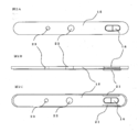
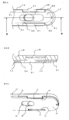
- FIG. 2A is a top plan view
- FIG. 2B is a side view
- FIG. 2C is a bottom plan view
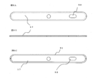
- FIG. 3A is an upper plan view
- FIG. 3B is a side view
- FIG. 3C is a lower plan view
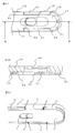
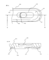
- 4A shows a structure in which the insulating plate of Example 1 is assembled to the lid body of the embodiment
- FIG. 4A is a plan view of the main part when the lid body is viewed from the outer can side
- FIG. 4B is a cross-sectional view taken along line AA of FIG.
- FIG. 4C is a partial perspective view of the lid as viewed from the exterior can side.
- FIG. 4A shows a structure in which the insulating plate of Example 1 is assembled to the lid body of the embodiment
- FIG. 4A is a plan view of the main part when the lid body is viewed from the outer can side
- FIG. 4B is a cross-sectional view taken along line AA of FIG.
- FIG. 4C is a
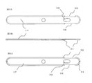
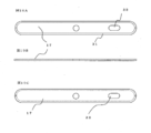
- FIG. 5A is an upper plan view
- FIG. 5B is a side view
- FIG. 5C is a lower plan view
- 6A shows a structure in which the insulating plate of Example 2 is assembled to the lid body of the embodiment
- FIG. 6A is a plan view of a main part when the lid body is viewed from the outer can side
- FIG. 6B is a cross-sectional view taken along line BB of FIG.
- FIG. 6C is a partial perspective view of the lid as viewed from the exterior can side.
- FIG. 7A is an upper plan view
- FIG. 7B is a side view
- FIG. 7C is a lower plan view.
- FIG. 8A is an upper plan view
- FIG. 8B is a side view
- FIG. 8C is a lower plan view.
- FIG. 9A shows a structure in which the insulating plate of Comparative Example 1 is assembled to the lid of the comparative example
- FIG. 9A is a plan view of the main part when the lid is viewed from the exterior can side
- FIG. 9B is a cross-sectional view taken along the line CC of FIG. is there.
- FIG. 10A is an upper plan view
- FIG. 10B is a side view
- FIG. 10C is a lower plan view.
- 11A shows a structure in which the insulating plate of Comparative Example 2 is assembled to the lid of the comparative example
- FIG. 11A is a plan view of the main part when the lid is viewed from the outer can side
- FIG. 11B is a cross-sectional view taken along DD in FIG. is there.
- a mode for carrying out the present invention will be described with reference to a non-aqueous electrolyte secondary battery as an example of a rectangular sealed battery.
- this invention is not limited to the following form, In the range which does not change the summary, it can change suitably and can implement.
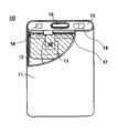
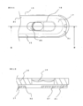
- FIG. 1 is a partial perspective schematic view of a rectangular sealed battery according to an embodiment of the present invention.
- 2 to 11 are diagrams relating to the structure of the lid and the insulating plate of the rectangular sealed battery according to Examples 1 and 2 and Comparative Examples 1 and 2.
- FIG. 1 is a partial perspective schematic view of a rectangular sealed battery according to an embodiment of the present invention.
- 2 to 11 are diagrams relating to the structure of the lid and the insulating plate of the rectangular sealed battery according
- the nonaqueous electrolyte secondary battery 10 of the example has a rectangular bottomed exterior made of an aluminum alloy together with an electrode body 12 in which a positive electrode plate and a negative electrode plate are spirally wound through a separator. It is stored in the can 11.
- a negative electrode current collecting tab is led out from the negative electrode plate and connected to the negative electrode terminal 18 of the lid 15.
- a portion where the aluminum foil core of the positive electrode plate is exposed is disposed on the outer periphery of the electrode body, and a positive electrode current collecting tab 13 is disposed.
- the positive electrode current collecting tab is formed by cutting an aluminum foil core into a U-shape and turning the cut back to form a positive electrode current collecting tab.
- the positive electrode current collecting tab is sandwiched in a gap between the fitting portion between the lid 15 and the outer can 11 opening, and is laser welded together with the lid 15 and the outer can 11 opening.
- the lid 15 is provided with a hole for injecting an electrolyte, and is sealed with a sealing plug 14 after the electrolyte is injected.
- a safety valve 16 is provided for releasing abnormal battery internal pressure.
- An insulating plate 17 is disposed between the lid 15 and the electrode body 12 to insulate each other.
- the method for producing the non-aqueous electrolyte secondary battery is as follows.
- ⁇ Preparation of positive electrode plate 95 parts by mass of lithium cobaltate (LiCoO 2 ) and 5 parts by mass of a carbon material as a conductive agent are mixed, and 95 parts by mass of this mixture and 5 parts by mass of polyvinylidene fluoride as a binder are mixed with N-methyl-2-
- a positive electrode mixture slurry was prepared by dispersing in pyrrolidone (NMP). This slurry was uniformly applied to both surfaces of a 13 ⁇ m thick aluminum foil by a doctor blade method.
- the slurry is not applied to the portion of the electrode body that is to be positioned on the outer peripheral portion, so that the aluminum foil is exposed, and the portion that is to be the positive electrode immediately below the outer peripheral aluminum foil layer is only one side.
- the slurry was applied. Thereafter, the slurry applied to the aluminum foil was dried by heating to produce a dry electrode plate having an active material layer formed on the aluminum foil. The dried electrode plate was compressed with a roller press and cut into predetermined dimensions to produce a positive electrode plate.
- Graphite as a negative electrode active material, styrene butadiene rubber as a binder, and carboxymethyl cellulose as a viscosity modifier were mixed at 95: 2: 3 (mass ratio), and this mixture was dispersed in water to prepare a slurry.
- This slurry was uniformly applied to both surfaces of a copper foil having a thickness of 8 ⁇ m by a doctor blade method. At this time, the slurry was not applied to the portion where the current collecting tab was to be attached, and the copper foil was exposed. Then, the slurry apply
- the positive electrode plate, the negative electrode plate, and a separator made of a polyethylene microporous film are wound into a cylindrical shape using a winder so that the positive electrode plate and the negative electrode plate are insulated by the separator, and then the cross section is formed into an oval shape.
- the electrode body 12 was produced.
- the electrode body may be produced by laminating a plurality of strip-shaped electrode plates through a separator.
- a lid 15 having a shape that fits into the outer can opening as shown in FIG. 2 was punched out by pressing an aluminum alloy plate having a thickness of 1.0 mm. At this time, the press mold was adjusted so that a thin portion having a length of 5.0 mm, a width of 2.0 mm, and a thickness of 80 ⁇ m was also formed at a predetermined position of the lid body 15. A coining process was applied to the thin wall portion, and a groove was formed so that the thin wall portion was easily cleaved to form a safety valve 16.
- the outer periphery of the surface of the lid 15 on the outer can side has a length (the lid body long side direction) of 6.0 mm, a width (the lid body short side direction) of 0.5 mm, and a height (the lid body).
- the thickness of the press) was adjusted so that a 0.4 mm lid rib 21 was also formed.
- a negative terminal mounting hole 22 and an electrolyte injection hole 23 were also formed in the lid 15 at the same time.
- the safety valve can also be manufactured by attaching a safety valve made of a metal foil separately manufactured to a hole formed in the lid 15 by a method such as welding.
- an insulating plate rib 31 having a height of 0.4 mm is provided on the outer periphery of the insulating plate 17, and a through hole 33 is provided at a position facing the safety valve 16 of the lid 15.
- the extrusion mold was adjusted so that the notch 32 to be fitted was provided, and the insulating plate 17 was produced by extruding the polypropylene resin into the mold.
- the through-hole 33 is provided at a position facing the safety valve 16 provided in the lid 15 when the through-hole 33 is assembled to the lid 15.
- the entire surface of the safety valve 16 may be exposed from the through-hole 33 in order to make the pressure release from the safety valve 16 smooth when viewed from the insulating plate 17 side after assembly. Further, in order to reduce the influence on the safety valve 16 when an impact is applied to the battery, only a part of the safety valve 16 may be exposed.
- the negative electrode terminal 18 was attached by caulking the insulating plate 17, the gasket (not shown) and the negative electrode terminal plate (not shown) to the negative electrode terminal attachment hole 22 of the lid 15 using the negative electrode terminal rivet 18.
- the notch 32 of the insulating plate 16 was fitted into the lid rib 21, and the insulating plate rib 31 was attached toward the surface on the electrode body side.
- the negative electrode current collecting tab led out from the electrode body 12 was welded to the negative electrode terminal plate, the electrode body 12 was accommodated in the outer can 11, and the opening of the outer can 11 and the lid body 15 were fitted.
- the positive electrode current collecting tab 13 was sandwiched between the opening of the outer can 11 and the lid, and the opening of the outer can 11 and the fitting portion of the outer cover 11 were laser welded together with the positive electrode current collecting tab 13. Then, a predetermined amount of the electrolyte was injected from the liquid injection hole 23 and sealed with the sealing plug 14.
- a prismatic nonaqueous electrolyte secondary battery having a height of 56 mm, a width of 38 mm, and a thickness of 4.7 mm and a design capacity of 1240 mAh was produced.
- Example 1 The nonaqueous electrolyte secondary battery of Example 1 was produced as described above.
- Example 2 In the above embodiment, the insulating plate 17 as shown in FIG. 5 is the same as in Example 1 except that the insulating plate rib 31 is attached to the lid 15 so that the insulating plate rib 31 faces the lid side as shown in FIG. Thus, the nonaqueous electrolyte secondary battery of Example 2 was produced.
- Comparative Example 1 Comparative Example 1
- the lid 15 is not provided with the lid rib as shown in FIG. 7, and the insulating plate 17 that is not provided with the notch to be fitted with the lid rib as shown in FIG. Attached.
- the non-aqueous electrolyte secondary battery of Comparative Example 1 was manufactured in the same manner as in Example 1 except that the insulating plate rib 31 was directed to the surface on the electrode body side. did.
- Comparative Example 2 In the first comparative example, as shown in FIG. 10, an insulating plate 17 not provided with a notch to be fitted with the lid rib is used, and the insulating plate rib 31 of the insulating plate 17 is formed on the lid side surface as shown in FIG. A non-aqueous electrolyte secondary battery of Comparative Example 2 was produced in the same manner as Comparative Example 1 except that it was attached to the lid 15 so as to face.
- ⁇ Drop test> 10 nonaqueous electrolyte secondary batteries of Examples 1 and 2 and Comparative Examples 1 and 2 were each charged to 4.2 V with a constant current of 1 It at 25 ° C., and further to 1/50 It at 4.2 V A constant voltage charge was performed. Next, constant current discharge was performed at 25 ° C. to 2.75 V at a constant current of 1 It. Then, the battery was fixed to an iron block having a mass of 140 g (assuming the mass of the mobile phone), and dropped from a height of 1.5 m onto the concrete floor so that the battery lid 15 faced the concrete floor. At this time, the battery did not collide directly with the concrete floor, but was dropped so that only the iron block collided. The number of drops until the safety valve opened and the electrolyte leaked out was recorded.
- Table 1 shows the test results of the above examples and comparative examples.
- Example 1 and 2 in which the lid is not provided on the lid both the average number of times until the electrolyte leaks out and the minimum number and the maximum number of times increase, and the reliability of the drop is improved.
- Example 1 in which the insulating plate rib is provided on the surface on the electrode body side is compared with Example 2 in which the insulating plate rib is provided on the surface on the lid side, until Example 2 leaks out the electrolyte. It can be seen that the average number of drops and the minimum and maximum number of drops are increased, further improving the reliability of drops.
- the lid rib prevents the electrolyte from reaching the vicinity of the safety valve, so that the amount of the electrolyte collected near the safety valve is smaller than that of the comparative example. Therefore, it is considered that the pressure applied to the safety valve is smaller than that of the comparative example, and the number of drops until the safety valve is opened is increased.
- a space is generated between the safety valve and the insulating plate by the insulating plate rib.
- the generated space is considered to relieve the pressure generated by compressing the gas in the battery internal space as the electrode body moves when the battery is dropped. Therefore, combined with the effect of the lid rib, it is considered that the number of drops until the safety valve was opened further increased.
- a rectangular sealed battery having excellent drop reliability can be provided, so that industrial applicability is great.
- Nonaqueous electrolyte secondary battery 11 Exterior can 12 Electrode body 15 Cover body 16 Safety valve 17 Insulation plate 21 Cover body rib 31 Insulation plate rib 32 Notch
Landscapes
- Chemical & Material Sciences (AREA)
- Chemical Kinetics & Catalysis (AREA)
- Electrochemistry (AREA)
- General Chemical & Material Sciences (AREA)
- Gas Exhaust Devices For Batteries (AREA)
- Sealing Battery Cases Or Jackets (AREA)
Abstract
【課題】 角形密閉電池を落下させたときに安全弁が開裂して電解質が漏れ出ることを防止した信頼性の高い電池を提供する。 【解決手段】 角形密閉電池は、蓋体と電極体との間に、安全弁と対向する位置に透孔が設けられ、かつ外周に絶縁板リブと切り欠きが設けられた絶縁板を備える。そして、蓋体は、互いに対向する1対の長辺の外周部で蓋体の電池内部側の面であって、安全弁近傍に1対の蓋体リブを備え、蓋体リブは絶縁板の切り欠きと嵌め合せられている構成とする。
Description
本発明は角形密閉電池に関する。
リチウムイオン電池、ニッケル水素蓄電池、ニッケルカドミウム蓄電池に代表される密閉電池は、携帯機器などの電源や、電動工具や電気自動車などの電源、バックアップ用電源など、多岐にわたり利用されている。
例えば密閉電池の中で、外装缶に角筒状のアルミニウム合金を用いる角形リチウムイオン電池は、軽量で高エネルギー密度を備え、携帯機器に効率よく収納できることから、携帯電話などの小型携帯機器の電源として大きなシェアを持つに至っている。
このような角形リチウムイオン電池は、正極活物質としては、リチウムイオンを可逆的に吸蔵放出可能なコバルト酸リチウム、ニッケル酸リチウム、マンガン酸リチウムなど、リチウム遷移金属酸化物が用いられる。そして正極活物質は結着剤や導電剤等と混合され、正極芯体としてのアルミニウム箔上に塗布されて正極板として用いられる。
一方、負極活物質としては、天然黒鉛、人造黒鉛、コークスなどの炭素質材料が用いられる。そして負極活物質は結着剤等と混合され、負極芯体としての銅箔上に塗布されて負極板として用いられる。
正極板と負極板は所定の寸法に加工されて、ポリエチレンなどの樹脂製微多孔セパレータを介して巻き取られて電極体をなし、電解質とともに外装缶へ収納される。そして蓋体を外装缶開口に嵌合させ、蓋体と外装缶開口とを溶接して封口する。
蓋体は、外部端子、電解質を注入するときに用いる注液孔、電池の内部圧力が異常に上昇したときに圧力を逃すための安全弁などを備える。蓋体に取り付けられる安全弁は、蓋体の一部をプレスにより金属箔状に加工したり、予め蓋体に開けられた孔に金属箔を溶接して作製される。
このように作製される安全弁は、電池内部の異常な圧力をできるだけ早く逃すべく、また安全弁の開裂が一定の圧力範囲で安定するように設計される。
ところが、近年に見られる携帯機器の高機能化にともない、それらの機器の電源としての電池には高容量で大型の電池が求められている。さらにコストダウンの要求から、角形電池を備えるパック電池の構造も簡素化される傾向にある。それに伴い、携帯機器が落下される等により衝撃を受けたときに、電池は大きな衝撃を受けやすくなり、電池の信頼性を従来以上に考慮する必要が生じている。
例えば、特許文献1、2のように、電池が衝撃を受けることで、安全弁が開裂をしてしまう不具合が生じうる。そして安全弁が開裂すると、そこから電解質が漏れ出し、携帯機器の故障の原因となりうる。
特許文献1、2とも蓋体と電極体との間に設置する絶縁板の構造を工夫することにより、安全弁開裂を防止することを提案している。
しかしながら、特許文献のような改良を施してもなお衝撃による安全弁の開裂が生じるおそれがあり、さらなる改良が求められた。
本発明は、上述の課題を解決するためになされたもので、その目的は、電池が衝撃を受けたときに安全弁の開裂が生じにくい、信頼性の高い密閉電池を提供することにある。
上述の課題を解決するために、本発明の角形密閉電池は、開口部を有する角形外装缶と、外装缶に収納された電極体および電解質と、外装缶の開口部に嵌合され開口部に溶接された蓋体と、蓋体と電極体との間に配された絶縁板とを備えた角形密閉電池であって、蓋体は、蓋体よりも厚さが薄い安全弁を備えると共に、安全弁の近傍でかつ蓋体の外周の互いに対向する一対の長辺近傍に電池の内部側へ突出する一対の蓋体リブを備え、絶縁板は、安全弁と対向する位置に透孔を備える板状部と、板状部の外周に設けられた絶縁板リブとからなり、絶縁板リブには切り欠き部があり、蓋体リブが絶縁板の切り欠き部に嵌め合せられている構造とする。
また、本発明の角形密閉電池は、絶縁板リブは絶縁板の蓋体側の面に設けられ、安全弁の近傍には蓋体と絶縁板の板状部との間に空間が設けられている構造とすることができる。
また、本発明の角形密閉電池は、蓋体リブの前記蓋体長辺方向の長さは、安全弁の前記蓋体長辺方向の長さの110%以上150%以下であり、蓋体リブの1つあたりの蓋体短辺方向の長さは、(蓋体の短辺方向長さ-安全弁の蓋体短辺方向の長さ)÷2未満であり、蓋体リブの蓋体厚さ方向の長さは、絶縁板の厚さ以上とすることができる。
本発明によれば、蓋体と電極体との間に配される絶縁板は外周に絶縁板リブを備えるため、絶縁板の強度が増し、電池が衝撃を受けて電極体が移動しようとしても絶縁板の変形が制限され、電極体の移動自体が制限される。このことにより、安全弁に向かって、絶縁板や電極体が移動することにより外装缶内の空間に存在する気体が圧縮されて生じる圧力や、電極体に浸透せずに外装缶内に存在する電解質が移動することにより生じる圧力を低減できるので、電池が衝撃を受けることによる安全弁開裂を抑制することが可能となる。さらに、蓋体の安全弁近傍に蓋体リブが設けられることで、電池が蓋体を下にして衝撃を受けたときに、外装缶の内面を伝わって電解質が安全弁周辺に集まることを抑制できるので、さらに効果的に安全弁の開裂を抑制することが可能となる。なお、蓋体リブが位置する安全弁の近傍かつ蓋体の外周の互いに対向する一対の長辺近傍とは、蓋体長辺の外周又は外周近くであって、安全弁に沿うような位置である。
また、本発明によれば、絶縁板リブが絶縁板の蓋体側の面に設けられると、絶縁板リブが絶縁板の電極体側の面に設けられている時より、蓋体と絶縁板の板状部分との間に空間が生じる。電池が衝撃を受けたときにこの空間が大きいと、絶縁板や電極体の移動により外装缶内の空間に存在する気体が圧縮されて生じる圧力が緩和されるので、より効果的に電池が衝撃を受けることによる安全弁の開裂を抑制することが可能となるので好ましい。
また、本発明によれば、蓋体リブの蓋体長辺方向の長さは、安全弁の蓋体長辺方向の長さの110%以上150%以下であり、蓋体リブの1つあたりの蓋体短辺方向の長さは、(前記蓋体の短辺方向長さ-前記安全弁の蓋体短辺方向の長さ)÷2未満であり、蓋体リブの蓋体厚さ方向の長さは、絶縁板の厚さ以上とすることで、蓋体に安全弁や蓋体リブを、プレス加工を用いて容易に作製することが可能となる。また、適度な大きさの蓋体リブの存在が外装缶開口と蓋体との溶接強度を低下させることなく、安全弁周囲へ外装缶内面を伝わって集まる電解質を効果的に抑制することが可能となるので好ましい。ここで絶縁板の厚さとは、絶縁板リブの高さを含めるものとする。つまりは、一対の蓋体リブと、一方および対向する他方のリブ端部の高さ方向の辺同士をつないでできる仮想面2つと、蓋体の面の一部を用いて仮想の箱状の立体を形成するとしたとき、その仮想の箱の底面に安全弁が収まっている状態であることが好ましい。
本発明を実施するための形態を、角形密閉電池の一例として非水電解質二次電池を、図面に基づいて説明する。なお、本発明は下記の形態に限定されるものではなく、その要旨を変更しない範囲において適宜変更して実施することが可能である。
なお、図1は本発明の実施形態に係る角形密閉電池の部分透視概略図である。図2~11は実施例1~2および比較例1~2に係る角形密閉電池の蓋体と絶縁板の構造に係る図である。
[実施の形態]
実施例の非水電解質二次電池10は、図1に示すように、正極板と負極板とがセパレータを介して渦巻き状に巻回した電極体12が電解質と共にアルミニウム合金製の角形有底外装缶11に収納されている。負極板からは負極集電タブが導出されて蓋体15の負極端子18に接続されている。電極体の外周には正極板のアルミニウム箔芯体が露出する部分が配置され、正極集電タブ13が配置されている。正極集電タブはアルミニウム箔芯体を
コ字状に切り込みを入れ、その切り込みを折り返して正極集電タブをなしている。正極集電タブは、蓋体15と外装缶11開口部との嵌合部の隙間に挟み込まれ、蓋体15と外装缶11開口部とともにレーザ溶接される。蓋体15には電解質を注入するための孔が設けられ、電解質を注入後に、封止栓14で密封される。また、異常な電池内部圧力を逃すための安全弁16が設けられている。そして、蓋体15と電極体12の間には、互いを絶縁
するために絶縁板17が配置される。
上記非水電解質二次電池の作製方法は以下のとおりである。
<正極板の作製>
コバルト酸リチウム(LiCoO2)95質量部と、導電剤として炭素材料5質量部とを混合し、この混合物95質量部と、結着剤としてポリフッ化ビニリデン5質量部とをN-メチル-2-ピロリドン(NMP)に分散させて正極合剤スラリーを調製した。このスラリーをドクターブレード法により、厚さ13μmのアルミニウム箔の両面に均一に塗布した。このとき、電極体の外周部に位置する予定の部分にはスラリーを塗布せず、アルミ
ニウム箔が露出するようにし、外周のアルミニウム箔のみの層のすぐ下層の正極になる予定の部分は片面のみにスラリーを塗布した。その後、アルミニウム箔に塗布したスラリーを加熱乾燥して、アルミニウム箔上に活物質層が形成された乾燥極板を作製した。乾燥極板をローラープレス機で圧縮し、所定の寸法に裁断し、正極板を作製した。
<負極板の作製>
負極活物質として黒鉛と、結着剤としてスチレンブタジエンゴムと、粘度調整剤としてカルボキシメチルセルロースとを95:2:3(質量比)で混合し、この混合物を水に分散してスラリーを調製した。このスラリーをドクターブレード法により、厚さ8μmの銅箔の両面に均一に塗布した。このとき、集電タブを取り付ける予定の部分にはスラリーを塗布せず、銅箔が露出するようにした。その後、銅箔に塗布したスラリーを加熱乾燥して
、銅箔上に活物質層が形成された乾燥極板を作製した。乾燥極板をローラープレス機で圧縮し、所定の寸法に裁断後、ニッケル製の集電タブを取り付けて負極板を作製した。
負極活物質として黒鉛と、結着剤としてスチレンブタジエンゴムと、粘度調整剤としてカルボキシメチルセルロースとを95:2:3(質量比)で混合し、この混合物を水に分散してスラリーを調製した。このスラリーをドクターブレード法により、厚さ8μmの銅箔の両面に均一に塗布した。このとき、集電タブを取り付ける予定の部分にはスラリーを塗布せず、銅箔が露出するようにした。その後、銅箔に塗布したスラリーを加熱乾燥して
、銅箔上に活物質層が形成された乾燥極板を作製した。乾燥極板をローラープレス機で圧縮し、所定の寸法に裁断後、ニッケル製の集電タブを取り付けて負極板を作製した。
<電極体の作製>
上記正極板と負極板とポリエチレン微多孔膜からなるセパレータとを、正極板と負極板がセパレータにより絶縁されるように、巻き取り機を用いて円筒状に巻回し、その後断面が長円形状になるように成型して電極体12を作製した。なお、電極体は、短冊状の複数枚の極板をセパレータを介して複数層積層して作製してもよい。
上記正極板と負極板とポリエチレン微多孔膜からなるセパレータとを、正極板と負極板がセパレータにより絶縁されるように、巻き取り機を用いて円筒状に巻回し、その後断面が長円形状になるように成型して電極体12を作製した。なお、電極体は、短冊状の複数枚の極板をセパレータを介して複数層積層して作製してもよい。
<電解質の調製>
エチレンカーボネートとエチルメチルカーボネートとジエチルカーボネートを体積比で20:50:30(25℃、1気圧)の割合で混合した非水溶媒に、電解質塩として六フッ化リン酸リチウムを0.9モル/リットル溶解した。
エチレンカーボネートとエチルメチルカーボネートとジエチルカーボネートを体積比で20:50:30(25℃、1気圧)の割合で混合した非水溶媒に、電解質塩として六フッ化リン酸リチウムを0.9モル/リットル溶解した。
<蓋体の作製>
厚さ1.0mmのアルミニウム合金板をプレス加工により、図2のような外装缶開口と嵌合する形状の蓋体15を打ち出した。このとき、蓋体15の所定位置に長さ5.0mm、幅2.0mmで厚さ80μmの薄肉部も形成されるようにプレス金型を調整した。この薄肉部にコイニング加工を用いて、薄肉部の開裂が容易になるように溝を付けて安全弁16とした。さらに、安全弁の近傍であって、蓋体15の外装缶側の面の外周に長さ(蓋体
長辺方向)6.0mm、幅(蓋体短辺方向)0.5mm、高さ(蓋体厚さ方向)0.4mmの蓋体リブ21も形成されるようにプレス金型を調整した。また、蓋体15には、負極端子取り付け孔22や、電解質注液孔23も同時に形成した。なお安全弁は、蓋体15に形成した孔へ、別途作製した金属箔からなる安全弁を溶接などの方法により取り付けても作製可能である。
<絶縁板の作製>
図3のように、高さ0.4mmの絶縁板リブ31が絶縁板17の外周に設けられ、蓋体15の安全弁16に対向する位置に透孔33が設けられ、さらに蓋体リブ21に嵌め合される切り欠き32が設けられるように押し出し金型を調整し、ポリプロピレン樹脂をその金型に押し出すことにより、絶縁板17を作製した。なお、透孔33は蓋体15に組み付けられたときに、蓋体15に設けられた安全弁16に対向する位置に設けられる。組み付け後に絶縁板17側から眺めたときに、安全弁16からの圧力放出をスムースにするために、透孔33から安全弁16の全面が露出していてもよい。また、電池に衝撃が加わったときの安全弁16への影響を小さくするために、安全弁16の一部だけが露出していてもよい。
図3のように、高さ0.4mmの絶縁板リブ31が絶縁板17の外周に設けられ、蓋体15の安全弁16に対向する位置に透孔33が設けられ、さらに蓋体リブ21に嵌め合される切り欠き32が設けられるように押し出し金型を調整し、ポリプロピレン樹脂をその金型に押し出すことにより、絶縁板17を作製した。なお、透孔33は蓋体15に組み付けられたときに、蓋体15に設けられた安全弁16に対向する位置に設けられる。組み付け後に絶縁板17側から眺めたときに、安全弁16からの圧力放出をスムースにするために、透孔33から安全弁16の全面が露出していてもよい。また、電池に衝撃が加わったときの安全弁16への影響を小さくするために、安全弁16の一部だけが露出していてもよい。
<電池の組み立て>
絶縁板17とガスケット(不図示)と負極端子板(不図示)を、負極端子リベット18を用いて、蓋体15の負極端子取り付け孔22へかしめ付けることにより負極端子18を取り付けた。このとき、図4のように絶縁板16の切り欠き32を蓋体リブ21に嵌め合し、そして絶縁板リブ31を電極体側の面に向けて取り付けた。電極体12から導出される負極集電タブを負極端子板に溶接し、電極体12を外装缶11に収納して外装缶11の
開口と蓋体15とを嵌合した。このとき正極集電タブ13は外装缶11の開口と蓋体との間に挟み込み、正極集電タブ13と共に外装缶11の開口と蓋体の嵌合部分をレーザ溶接した。そして注液孔23から上記の電解質を所定量注入して、封止栓14で密封した。このようにして、高さ56mm、幅38mm、厚さ4.7mmで、設計容量1240mAhの角形非水電解質二次電池を作製した。
(実施例1)
上記のようにして実施例1の非水電解質二次電池を作製した。
上記のようにして実施例1の非水電解質二次電池を作製した。
(実施例2)
上記実施の形態において、図5に示すような絶縁板17を、図6に示すように絶縁板リブ31が蓋体側の面に向くように蓋体15に取り付けたこと以外は実施例1と同様にして実施例2の非水電解質二次電池を作製した。
上記実施の形態において、図5に示すような絶縁板17を、図6に示すように絶縁板リブ31が蓋体側の面に向くように蓋体15に取り付けたこと以外は実施例1と同様にして実施例2の非水電解質二次電池を作製した。
(比較例1)
上記実施の形態において、蓋体15には図7のように蓋体リブを設けず、図8に示すように、蓋体リブと嵌め合せる切り欠きを設けていない絶縁板17を蓋体15に取り付けた。このとき絶縁板17は図9に示すように、絶縁板リブ31が電極体側の面に向くようにしたこと以外は実施例1と同様にして、比較例1の非水電解質二次電池を作製した。
上記実施の形態において、蓋体15には図7のように蓋体リブを設けず、図8に示すように、蓋体リブと嵌め合せる切り欠きを設けていない絶縁板17を蓋体15に取り付けた。このとき絶縁板17は図9に示すように、絶縁板リブ31が電極体側の面に向くようにしたこと以外は実施例1と同様にして、比較例1の非水電解質二次電池を作製した。
(比較例2)
上記比較例1において、図10に示すように、蓋体リブと嵌め合せる切り欠きを設けていない絶縁板17を用い、図11のように絶縁板17の絶縁板リブ31は蓋体側の面に向くように蓋体15に取り付けたこと以外は比較例1と同様にして、比較例2の非水電解質二次電池を作製した。
上記比較例1において、図10に示すように、蓋体リブと嵌め合せる切り欠きを設けていない絶縁板17を用い、図11のように絶縁板17の絶縁板リブ31は蓋体側の面に向くように蓋体15に取り付けたこと以外は比較例1と同様にして、比較例2の非水電解質二次電池を作製した。
<落下試験>
実施例1、2および比較例1、2の非水電解質二次電池各10個を、それぞれ25℃で1Itの定電流で4.2Vまで充電し、さらに4.2Vで1/50Itになるまで定電圧充電を行った。次に25℃で1Itの定電流で2.75Vまで定電流放電を行った。そして電池を質量140gの鉄ブロック(携帯電話の質量を想定)に固定し、高さ1.5mからコンクリート床へ、電池の蓋体15がコンクリート床方向を向くように落下させた。こ
のとき、コンクリート床には電池は直接衝突せず、鉄ブロックのみが衝突するように落下させた。そして安全弁が開裂して電解質が漏れ出るまでの落下回数を記録した。
実施例1、2および比較例1、2の非水電解質二次電池各10個を、それぞれ25℃で1Itの定電流で4.2Vまで充電し、さらに4.2Vで1/50Itになるまで定電圧充電を行った。次に25℃で1Itの定電流で2.75Vまで定電流放電を行った。そして電池を質量140gの鉄ブロック(携帯電話の質量を想定)に固定し、高さ1.5mからコンクリート床へ、電池の蓋体15がコンクリート床方向を向くように落下させた。こ
のとき、コンクリート床には電池は直接衝突せず、鉄ブロックのみが衝突するように落下させた。そして安全弁が開裂して電解質が漏れ出るまでの落下回数を記録した。
上記の各実施例および比較例の試験結果を表1に示す。

蓋体に蓋体リブが設けられ、絶縁板の凹部と封口体リブとが嵌め合されている実施例1、2と、蓋体に蓋体リブが設けられていない比較例1、2とを比較すると、実施例1、2の方が、電解質が漏れ出るまでの平均回数と最小回数・最大回数ともに多くなり、落下の信頼性が向上していることが判る。また、絶縁板リブが電極体側の面に設けられている実施例1と、絶縁板リブが蓋体側の面に設けられている実施例2とを比較すると、実施例2が電解質の漏れ出るまでの平均落下回数や最小回数・最大回数が多くなり、落下の信頼性がさらに向上していることが判る。
これは以下のように考えられる。すなわち、比較例では、実施例と異なり蓋体リブがなく、絶縁板には絶縁板リブがあるものの、衝撃により蓋体と絶縁板リブの間に隙間が生じる。電解質は外装缶内面を伝わって、蓋体と絶縁板リブとの隙間などから安全弁付近まで到達する。安全弁付近の電解質は、電池の落下時の電極体の移動と相まって安全弁に圧力を加えるので、安全弁が開裂しやすくなる。
一方、実施例では、蓋体リブが安全弁付近への電解質の到達を妨げることにより、安全弁付近へ集まる電解質の量が比較例よりも少なくなる。したがって、安全弁に加えられる圧力が比較例より小さくなり、安全弁開裂までの落下回数が増えたものと考えられる。
また、実施例2のように絶縁板リブが蓋体側の面の設けられると、絶縁板リブにより安全弁と絶縁板との間に空間が生じる。生じた空間は、電池落下時の電極体移動の伴い電池内部空間の気体が圧縮されて生じる圧力を緩和させると考えられる。したがって、蓋体リブの効果と相まって、安全弁開裂までの落下回数がさらに増えたものと考えられる。
本発明によれば、落下信頼性に優れる角形密閉電池を提供できるので、産業上の利用可能性が大である。
10 非水電解質二次電池
11 外装缶
12 電極体
15 蓋体
16 安全弁
17 絶縁板
21 蓋体リブ
31 絶縁板リブ
32 切り欠き
11 外装缶
12 電極体
15 蓋体
16 安全弁
17 絶縁板
21 蓋体リブ
31 絶縁板リブ
32 切り欠き
Claims (3)
- 開口部を有する角形外装缶と、前記外装缶に収納された電極体および電解質と、前記外装缶の開口部に嵌合され前記開口部に溶接された蓋体と、前記蓋体と電極体との間に配された絶縁板とを備えた角形密閉電池であって、
前記蓋体は、前記蓋体よりも厚さが薄い安全弁を備えると共に、前記安全弁の近傍でかつ前記蓋体の外周の互いに対向する一対の長辺近傍に電池の内部側へ突出する一対の蓋体リブを備え、
前記絶縁板は、前記安全弁と対向する位置に透孔を備える板状部と、前記板状部の外周に設けられた絶縁板リブとからなり、前記絶縁板リブには切り欠き部があり、
前記蓋体リブが前記絶縁板の切り欠き部に嵌め合せられていることを特徴とする角形密閉電池。 - 前記絶縁板リブは前記絶縁板の蓋体側の面に設けられ、前記安全弁の近傍では、前記蓋体と前記絶縁板の板状部との間に空間が設けられていることを特徴とする請求項1に記載の角形密閉電池。
- 前記蓋体リブの前記蓋体長辺方向の長さは、前記安全弁の前記蓋体長辺方向の長さの110%以上150%以下であり、
前記蓋体リブの1つあたりの前記蓋体短辺方向の長さは、(前記蓋体の短辺方向長さ-前記安全弁の前記蓋体短辺方向の長さ)÷2未満であり、
前記蓋体リブの前記蓋体厚さ方向の長さは、前記絶縁板の厚さ以上であることを特徴とする請求項1または2に記載の角形密閉電池。
Applications Claiming Priority (2)
| Application Number | Priority Date | Filing Date | Title |
|---|---|---|---|
| JP2010213829 | 2010-09-24 | ||
| JP2010-213829 | 2010-09-24 |
Publications (1)
| Publication Number | Publication Date |
|---|---|
| WO2012039247A1 true WO2012039247A1 (ja) | 2012-03-29 |
Family
ID=45873737
Family Applications (1)
| Application Number | Title | Priority Date | Filing Date |
|---|---|---|---|
| PCT/JP2011/069727 Ceased WO2012039247A1 (ja) | 2010-09-24 | 2011-08-31 | 角形密閉電池 |
Country Status (1)
| Country | Link |
|---|---|
| WO (1) | WO2012039247A1 (ja) |
Cited By (1)
| Publication number | Priority date | Publication date | Assignee | Title |
|---|---|---|---|---|
| US20240195001A1 (en) * | 2022-12-08 | 2024-06-13 | Ford Global Technologies, Llc | Battery enclosure and method of manufacturing a battery enclosure |
Citations (4)
| Publication number | Priority date | Publication date | Assignee | Title |
|---|---|---|---|---|
| JP2004152581A (ja) * | 2002-10-30 | 2004-05-27 | Matsushita Electric Ind Co Ltd | 角型リチウムイオン二次電池 |
| JP2006093151A (ja) * | 2004-09-24 | 2006-04-06 | Samsung Sdi Co Ltd | リチウム二次電池 |
| JP2006147422A (ja) * | 2004-11-22 | 2006-06-08 | Nec Access Technica Ltd | 電池及び電池パック |
| JP2006351234A (ja) * | 2005-06-13 | 2006-12-28 | Fuji Hatsujo Kk | 密閉型電池用封口板とその製造用金型及び製造方法 |
-
2011
- 2011-08-31 WO PCT/JP2011/069727 patent/WO2012039247A1/ja not_active Ceased
Patent Citations (4)
| Publication number | Priority date | Publication date | Assignee | Title |
|---|---|---|---|---|
| JP2004152581A (ja) * | 2002-10-30 | 2004-05-27 | Matsushita Electric Ind Co Ltd | 角型リチウムイオン二次電池 |
| JP2006093151A (ja) * | 2004-09-24 | 2006-04-06 | Samsung Sdi Co Ltd | リチウム二次電池 |
| JP2006147422A (ja) * | 2004-11-22 | 2006-06-08 | Nec Access Technica Ltd | 電池及び電池パック |
| JP2006351234A (ja) * | 2005-06-13 | 2006-12-28 | Fuji Hatsujo Kk | 密閉型電池用封口板とその製造用金型及び製造方法 |
Cited By (2)
| Publication number | Priority date | Publication date | Assignee | Title |
|---|---|---|---|---|
| US20240195001A1 (en) * | 2022-12-08 | 2024-06-13 | Ford Global Technologies, Llc | Battery enclosure and method of manufacturing a battery enclosure |
| US12355095B2 (en) * | 2022-12-08 | 2025-07-08 | Ford Global Technologies, Llc | Battery enclosure and method of manufacturing a battery enclosure |
Similar Documents
| Publication | Publication Date | Title |
|---|---|---|
| JP6250567B2 (ja) | 密閉型電池 | |
| US7378185B2 (en) | Prismatic lithium secondary battery having a porous heat resistant layer | |
| JP6538650B2 (ja) | 円筒形密閉電池 | |
| JP6490053B2 (ja) | 円筒形密閉電池及び電池パック | |
| JP6254102B2 (ja) | 密閉型電池 | |
| US20110111280A1 (en) | Lithium-ion secondary battery | |
| JP6424426B2 (ja) | 組電池 | |
| US20160254569A1 (en) | Assembled battery | |
| US7419743B2 (en) | Cylindrical lithium battery resistant to breakage of the porous heat resistant layer | |
| KR20130087968A (ko) | 전극 조립체 및 이를 구비하는 이차 전지 | |
| US20210234156A1 (en) | Non-aqueous electrolyte secondary battery | |
| JP2013026123A (ja) | 二次電池および電極板 | |
| JP2015125856A (ja) | 非水電解質二次電池及び非水電解質二次電池の製造方法 | |
| US11387495B2 (en) | Non-aqueous electrolyte secondary battery | |
| JP2013089441A (ja) | 電池用電極群およびこれを用いた電池 | |
| JP2013012320A (ja) | リチウムイオン二次電池 | |
| JP5459048B2 (ja) | 非水電解質二次電池 | |
| JP2021068588A (ja) | 非水電解液二次電池 | |
| JP4420484B2 (ja) | 密閉型電池 | |
| JP2006278184A (ja) | 角型電池及びその製造方法 | |
| JP2016058169A (ja) | 非水電解液二次電池とその製造方法 | |
| JP2014107054A (ja) | 密閉型電池 | |
| JP2009224094A (ja) | 角形密閉電池 | |
| JP2000182588A (ja) | リチウム二次電池 | |
| JPH04206341A (ja) | 電池 |
Legal Events
| Date | Code | Title | Description |
|---|---|---|---|
| 121 | Ep: the epo has been informed by wipo that ep was designated in this application |
Ref document number: 11826693 Country of ref document: EP Kind code of ref document: A1 |
|
| NENP | Non-entry into the national phase |
Ref country code: DE |
|
| 122 | Ep: pct application non-entry in european phase |
Ref document number: 11826693 Country of ref document: EP Kind code of ref document: A1 |
|
| NENP | Non-entry into the national phase |
Ref country code: JP |