WO2012036238A1 - 血液と接触する表面の血小板付着性を減少させる医療用機器の製造方法 - Google Patents
血液と接触する表面の血小板付着性を減少させる医療用機器の製造方法 Download PDFInfo
- Publication number
- WO2012036238A1 WO2012036238A1 PCT/JP2011/071110 JP2011071110W WO2012036238A1 WO 2012036238 A1 WO2012036238 A1 WO 2012036238A1 JP 2011071110 W JP2011071110 W JP 2011071110W WO 2012036238 A1 WO2012036238 A1 WO 2012036238A1
- Authority
- WO
- WIPO (PCT)
- Prior art keywords
- electron beam
- beam irradiation
- blood
- titanium
- manufacturing
- Prior art date
Links
Images


Classifications
-
- A—HUMAN NECESSITIES
- A61—MEDICAL OR VETERINARY SCIENCE; HYGIENE
- A61L—METHODS OR APPARATUS FOR STERILISING MATERIALS OR OBJECTS IN GENERAL; DISINFECTION, STERILISATION OR DEODORISATION OF AIR; CHEMICAL ASPECTS OF BANDAGES, DRESSINGS, ABSORBENT PADS OR SURGICAL ARTICLES; MATERIALS FOR BANDAGES, DRESSINGS, ABSORBENT PADS OR SURGICAL ARTICLES
- A61L27/00—Materials for grafts or prostheses or for coating grafts or prostheses
- A61L27/02—Inorganic materials
- A61L27/04—Metals or alloys
- A61L27/06—Titanium or titanium alloys
-
- A—HUMAN NECESSITIES
- A61—MEDICAL OR VETERINARY SCIENCE; HYGIENE
- A61L—METHODS OR APPARATUS FOR STERILISING MATERIALS OR OBJECTS IN GENERAL; DISINFECTION, STERILISATION OR DEODORISATION OF AIR; CHEMICAL ASPECTS OF BANDAGES, DRESSINGS, ABSORBENT PADS OR SURGICAL ARTICLES; MATERIALS FOR BANDAGES, DRESSINGS, ABSORBENT PADS OR SURGICAL ARTICLES
- A61L31/00—Materials for other surgical articles, e.g. stents, stent-grafts, shunts, surgical drapes, guide wires, materials for adhesion prevention, occluding devices, surgical gloves, tissue fixation devices
- A61L31/02—Inorganic materials
- A61L31/022—Metals or alloys
-
- A—HUMAN NECESSITIES
- A61—MEDICAL OR VETERINARY SCIENCE; HYGIENE
- A61L—METHODS OR APPARATUS FOR STERILISING MATERIALS OR OBJECTS IN GENERAL; DISINFECTION, STERILISATION OR DEODORISATION OF AIR; CHEMICAL ASPECTS OF BANDAGES, DRESSINGS, ABSORBENT PADS OR SURGICAL ARTICLES; MATERIALS FOR BANDAGES, DRESSINGS, ABSORBENT PADS OR SURGICAL ARTICLES
- A61L33/00—Antithrombogenic treatment of surgical articles, e.g. sutures, catheters, prostheses, or of articles for the manipulation or conditioning of blood; Materials for such treatment
- A61L33/0094—Physical treatment, e.g. plasma treatment
-
- A—HUMAN NECESSITIES
- A61—MEDICAL OR VETERINARY SCIENCE; HYGIENE
- A61M—DEVICES FOR INTRODUCING MEDIA INTO, OR ONTO, THE BODY; DEVICES FOR TRANSDUCING BODY MEDIA OR FOR TAKING MEDIA FROM THE BODY; DEVICES FOR PRODUCING OR ENDING SLEEP OR STUPOR
- A61M60/00—Blood pumps; Devices for mechanical circulatory actuation; Balloon pumps for circulatory assistance
- A61M60/10—Location thereof with respect to the patient's body
- A61M60/104—Extracorporeal pumps, i.e. the blood being pumped outside the patient's body
- A61M60/109—Extracorporeal pumps, i.e. the blood being pumped outside the patient's body incorporated within extracorporeal blood circuits or systems
- A61M60/113—Extracorporeal pumps, i.e. the blood being pumped outside the patient's body incorporated within extracorporeal blood circuits or systems in other functional devices, e.g. dialysers or heart-lung machines
-
- A—HUMAN NECESSITIES
- A61—MEDICAL OR VETERINARY SCIENCE; HYGIENE
- A61M—DEVICES FOR INTRODUCING MEDIA INTO, OR ONTO, THE BODY; DEVICES FOR TRANSDUCING BODY MEDIA OR FOR TAKING MEDIA FROM THE BODY; DEVICES FOR PRODUCING OR ENDING SLEEP OR STUPOR
- A61M60/00—Blood pumps; Devices for mechanical circulatory actuation; Balloon pumps for circulatory assistance
- A61M60/20—Type thereof
- A61M60/205—Non-positive displacement blood pumps
- A61M60/216—Non-positive displacement blood pumps including a rotating member acting on the blood, e.g. impeller
- A61M60/226—Non-positive displacement blood pumps including a rotating member acting on the blood, e.g. impeller the blood flow through the rotating member having mainly radial components
- A61M60/232—Centrifugal pumps
-
- A—HUMAN NECESSITIES
- A61—MEDICAL OR VETERINARY SCIENCE; HYGIENE
- A61M—DEVICES FOR INTRODUCING MEDIA INTO, OR ONTO, THE BODY; DEVICES FOR TRANSDUCING BODY MEDIA OR FOR TAKING MEDIA FROM THE BODY; DEVICES FOR PRODUCING OR ENDING SLEEP OR STUPOR
- A61M60/00—Blood pumps; Devices for mechanical circulatory actuation; Balloon pumps for circulatory assistance
- A61M60/40—Details relating to driving
- A61M60/403—Details relating to driving for non-positive displacement blood pumps
- A61M60/419—Details relating to driving for non-positive displacement blood pumps the force acting on the blood contacting member being permanent magnetic, e.g. from a rotating magnetic coupling between driving and driven magnets
-
- C—CHEMISTRY; METALLURGY
- C22—METALLURGY; FERROUS OR NON-FERROUS ALLOYS; TREATMENT OF ALLOYS OR NON-FERROUS METALS
- C22F—CHANGING THE PHYSICAL STRUCTURE OF NON-FERROUS METALS AND NON-FERROUS ALLOYS
- C22F1/00—Changing the physical structure of non-ferrous metals or alloys by heat treatment or by hot or cold working
- C22F1/16—Changing the physical structure of non-ferrous metals or alloys by heat treatment or by hot or cold working of other metals or alloys based thereon
- C22F1/18—High-melting or refractory metals or alloys based thereon
- C22F1/183—High-melting or refractory metals or alloys based thereon of titanium or alloys based thereon
-
- A—HUMAN NECESSITIES
- A61—MEDICAL OR VETERINARY SCIENCE; HYGIENE
- A61M—DEVICES FOR INTRODUCING MEDIA INTO, OR ONTO, THE BODY; DEVICES FOR TRANSDUCING BODY MEDIA OR FOR TAKING MEDIA FROM THE BODY; DEVICES FOR PRODUCING OR ENDING SLEEP OR STUPOR
- A61M60/00—Blood pumps; Devices for mechanical circulatory actuation; Balloon pumps for circulatory assistance
- A61M60/10—Location thereof with respect to the patient's body
- A61M60/122—Implantable pumps or pumping devices, i.e. the blood being pumped inside the patient's body
- A61M60/126—Implantable pumps or pumping devices, i.e. the blood being pumped inside the patient's body implantable via, into, inside, in line, branching on, or around a blood vessel
- A61M60/148—Implantable pumps or pumping devices, i.e. the blood being pumped inside the patient's body implantable via, into, inside, in line, branching on, or around a blood vessel in line with a blood vessel using resection or like techniques, e.g. permanent endovascular heart assist devices
-
- Y—GENERAL TAGGING OF NEW TECHNOLOGICAL DEVELOPMENTS; GENERAL TAGGING OF CROSS-SECTIONAL TECHNOLOGIES SPANNING OVER SEVERAL SECTIONS OF THE IPC; TECHNICAL SUBJECTS COVERED BY FORMER USPC CROSS-REFERENCE ART COLLECTIONS [XRACs] AND DIGESTS
- Y10—TECHNICAL SUBJECTS COVERED BY FORMER USPC
- Y10T—TECHNICAL SUBJECTS COVERED BY FORMER US CLASSIFICATION
- Y10T29/00—Metal working
- Y10T29/49—Method of mechanical manufacture
- Y10T29/49229—Prime mover or fluid pump making
- Y10T29/49236—Fluid pump or compressor making
Definitions
- the present invention relates to a method for manufacturing a medical device, and more particularly to a method for manufacturing a medical device that reduces platelet adhesion on a surface that comes into contact with blood.
- titanium or titanium alloy base materials pure titanium (JIS type 1, type 2), ⁇ - ⁇ alloy, 6-4 alloy (JIS type 60, etc.), ⁇ alloy, 15-3-3-3 alloy, etc.
- Strength titanium alloys are known. Titanium or titanium alloy base materials used in medical metal equipment include ELI (Extra Low Interstitial), which is a material that keeps the content of oxygen, nitrogen, hydrogen and iron particularly low in 6-4 alloy and 6-4 alloy. Elements) material is known.
- the 6-4 alloy and ELI material have high strength and maintain stable strength even at high temperatures, but are difficult to cut and are not easily worn, and may cause seizure or galling.
- the manufacturing method of the medical device which consists of titanium or a titanium alloy base material is manufactured to a defined shape by performing machining, such as cutting, on the block material manufactured by the rolling process etc.
- End mills are mainly used for cutting, but the surface of medical equipment must be a surface that is difficult for bacteria to adhere to, and when it comes into contact with flowing blood, platelet adhesion is suppressed. It is necessary to have a surface that can suppress thrombus formation.
- the crystal grains on the surface become finer, leaving traces of cutting, and it is a big problem to obtain a surface that is difficult for bacteria to adhere to medical devices It becomes.
- buffing, chemical etching, blasting, and the like are performed after machining.
- polishing requires a long time.
- Patent Document 1 and Non-Patent Document 1 it is known that a pure titanium metal substrate of dental metal is irradiated with an electron beam to improve surface flatness, increase brightness, and improve corrosion resistance. It has been.
- mainly 6-4 titanium material other than pure titanium is included in the titanium material.
- impurities are boiled and vaporized on the surface of the electrode due to electron beam irradiation, minute depressions (hereinafter referred to as craters) may be generated, resulting in surface defects.
- craters minute depressions
- An object of the present invention is to provide a method for producing a medical device having a surface to which various bacteria are difficult to adhere or a surface that reduces platelet adhesion on a surface in contact with blood.
- (3) The electron beam irradiation is a first electron beam irradiation performed at a first voltage and a second electron beam irradiation performed at a second voltage higher than the first voltage (1) or (2) The manufacturing method of the medical device as described in 1 ..
- the medical device obtained by the production method of the present invention has low platelet adhesion on the surface that comes into contact with blood.
- the medical device obtained by another production method of the present invention reduces the platelet adhesion on the surface that comes into contact with blood, and a minute depression (so-called crater) that may occur due to electron beam irradiation. ) Is suppressed.
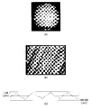
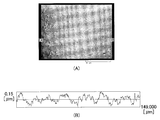
- FIG. 1 shows a metal surface obtained as a comparative material in Example 1.
- 1A is a metallographic micrograph (magnification 20 times) of the surface of a comparative material obtained in Example 1.
- FIG. 1B is a laser micrograph of the surface of the comparative material obtained in Example 1.
- FIG. 1C is a diagram showing the measurement results of the surface roughness of the surface of the comparative material obtained in Example 1.
- 2A is a TEM (transmission electron microscope) image photograph of the cross-section of the comparative material obtained in Example 1.
- FIG. FIG. 2 (B) is a TEM image photograph of the cross section of the substrate after SOLO irradiation.
- FIG. 3 is a schematic diagram for explaining a large-area electron beam irradiation apparatus.
- FIG. 3 is a schematic diagram for explaining a large-area electron beam irradiation apparatus.
- FIG. 4A is an exploded perspective view of the flow chamber.
- FIG. 4B is a plan view of the flow chamber.
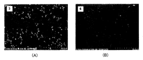
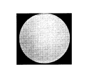
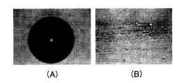
- FIG. 5 (A) is a photograph taken with a microscope showing the platelet adhesion state of the test piece 1A.
- FIG. 5B is a photograph of a metal surface that is not in contact with the blood flow taken under the same conditions as a comparison.
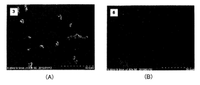
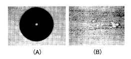
- FIG. 6 (A) is a photograph taken with a microscope showing the platelet adhesion state of the test piece 21A.
- FIG. 6B is a photograph of a metal surface that is not in contact with the blood flow taken under the same conditions as a comparison. It is a schematic diagram which shows the morphological change accompanying platelet activation.
- FIG. 11A is a laser micrograph showing the result of electron beam irradiation after SOLO irradiation in Example 2.
- FIG. 11B is a diagram showing a measurement result of the surface roughness of the surface of FIG.
- It is a metal micrograph (magnification 20 times) which shows the result of electron beam irradiation after SOLO irradiation of Example 2.
- 4 is a surface micrograph showing a metal structure showing the results of Example 3.
- FIG. 11A is a laser micrograph showing the result of electron beam
- FIG. 14A shows a surface metal micrograph (magnification 20 times) of the surface obtained in the first stage of Example 4.
- FIG. 14B shows a surface metal micrograph (magnification 20 times) of the surface obtained in the second stage of Example 4.
- FIG. It is a schematic diagram which shows the outline
- FIG. FIG. 17A shows a Rockwell impression, and FIG. 17B shows a wear trace.
- FIG. 18A shows the Rockwell impression and FIG. 18B shows the wear trace. It is a figure which shows the result of the abrasion resistance test of the surface which carried out DLC coating on the surface obtained in Example 5.
- FIG. 19A shows the Rockwell impression, and FIG. 19B shows the wear trace.
- 1 is a longitudinal sectional view of a centrifugal blood pump device described in JP-A-2005-270345.
- 1 is a cross-sectional view of a centrifugal blood pump device described in JP-A-2005-270345. It is sectional drawing which shows the state which removed the impeller from the cross-sectional view of the centrifugal blood pump apparatus of FIG.
- Titanium or titanium alloy base materials used for medical devices are pure titanium, JIS 1 type and JIS 2 type, Ti-6Al-4V (hereinafter referred to as 6-4 alloy), 6-4 alloy type ELI material (JIS61). ), Ti-6Al-2Nb-1Ta, Ti-15Zr-4Nb-4Ta, Ti-6Al-7Nb, Ti-3Al-2.5V, Ti-13Nb-13Zr, Ti-15Mo-5Zr-3Al, Ti-12Mo- 6Zr-2Fe, Ti-15Mo, etc.
- Titanium or a titanium alloy base material is made into a block material by rolling or the like, and is processed into a medical device shape by machining. Machining is not limited, and any processing method required for each medical device can be used. In the manufacturing method of the present invention, at least cutting is performed as machining, and an end mill is mainly used. In cutting, the results of surface observation after end milling, which is a comparative material of Example 1, are shown in FIGS. 1 (A), 1 (B), and 1 (C). As shown in FIG. 1, traces due to cutting are observed on a titanium or titanium alloy substrate other than pure titanium. In addition, FIG. 2A shows a transmission electron microscope (TEM) image of the cross section of the base material after end milling. Crystal grain refinement is also observed.
- TEM transmission electron microscope
- FIG. 3 shows a schematic assembly diagram of the electron beam irradiation apparatus used in the present invention.
- the electron beam irradiation apparatus of Explosive Electron Emission (EEE) method is shown.
- a sample 9 is placed in a vacuum chamber 1 that has been evacuated by the vacuum pump 2 and the auxiliary vacuum pump 3, and electrons emitted from the cathode 7 collide with the anode plasma 8 by the anode 6 to generate electrons ( Penning effect occurs.
- 5 is a solenoid
- 4 is an argon gas container.
- Titanium or titanium alloy after electron beam irradiation in 3 above is held in a flow chamber, and blood adjusted to have a hematocrit value of 40% and a platelet count of 1.5 ⁇ 10 5 / ⁇ L is flowed at a flow rate of 6 ml / h. The conditions were refluxed for 10 minutes.
- the titanium or titanium alloy substrate taken out from the flow chamber was washed, fixed, dehydrated and freeze-dried, and the state of platelets adhering to the surface and the morphological change accompanying activation were observed with a scanning electron microscope (SEM).
- SEM scanning electron microscope
- the flow chamber shown in FIG. 4 is: a silicone plate, titanium or titanium alloy base material, c Teflon TM spacer, d coating glass slide, e silicone plate, f metal plate in this order in an acrylic substrate. These materials are fastened with a constant torque using a g screw.
- the center part of the Teflon TM spacer is extracted in a square shape (for example, 10 mm ⁇ 10 mm). Blood that is fed from the inflow part of the acrylic substrate using a blood pump such as a syringe pump is a gap between the coating slide glass and the titanium or titanium alloy substrate, that is, a portion where the Teflon TM spacer is removed. And is drained from the outflow part of the acrylic substrate.
- a blood pump such as a syringe pump
- FIG. 5 shows the state of platelet adhesion in the test piece 1A not irradiated with the electron beam.
- FIG. 6 shows the platelet adhesion state on the test piece 21A after the electron beam irradiation. It can be seen that the platelet adhesion on the surface of the titanium or titanium alloy substrate is greatly reduced by electron beam irradiation. Further, as will be shown later in the Examples, it can be seen that the surface after electron beam irradiation is a surface that not only reduces the number of adhering platelets but also suppresses the activation of platelets.
- the crater is thought to be caused by impurities inside the substrate at a depth of about 2.1 microns and falling objects from the top of the substrate due to electron beam irradiation.
- the frequency of craters changes with subsequent electron beam irradiation depending on the machining speed, means, and load.
- craters minute surface depressions
- blood accumulates on the surface that comes into contact with blood or thrombi It becomes easy to do, and it is inferior to biocompatibility.
- Vacuum annealing is carried out under conditions of minutes to 3 hours, and then gradually cooled to room temperature. After vacuum annealing, electron beam irradiation is performed.
- Plasma cathode electron beam irradiation method Either of these may be performed.
- FIG. 1 An example of a plasma cathode electron beam irradiation apparatus is SOLO (manufactured by Nagata Seiki Co., Ltd., electron beam generation apparatus), and an outline thereof is shown in FIG.
- SOLO accelerates an electron beam by passing plasma generated by the hollow cathode 21 and the hollow anode 25 as a cathode and passing through a grid 29 to which a DC bias is applied to the electron beam.
- the sample 33 is irradiated.
- An electron beam with a diameter of 1 mm to 10 mm is scanned and scanned in the vicinity of the sample titanium or titanium alloy substrate.
- the surface of the end milled 6-4 alloy is scanned with a plasma cathode electron beam under the following conditions, preferably using the SOLO apparatus shown in FIG.
- the sample is slowly cooled in the apparatus.
- a TEM image of the cross section of the base material of Example 2 after SOLO irradiation is shown in FIG. In FIG. 2A, the crystal grains are refined after the cutting process, but after the SOLO irradiation in FIG.
- the electron beam irradiation is the same as the electron beam irradiation described in 3 above.
- the steps 5 and 6 are performed, the surface of the titanium or titanium alloy substrate in which the platelet adhesion on the surface in contact with blood is reduced and the formation of craters is suppressed can be obtained.
- the second electron beam irradiation is performed at a cathode voltage higher by 5 to 10 kV than the first electron beam irradiation. Conditions other than the cathode voltage are not limited, but may be the same conditions as those for the first electron beam irradiation.
- Electron beam irradiation is performed using pure titanium for the anode in reverse polarity.
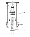
- An outline of the arrangement of the apparatus is shown in FIG.
- the apparatus is basically the same as the electron beam irradiation apparatus shown in FIG.
- the base material sample
- pure titanium is disposed on the lower anode 72.
- the upper cathode is made of a base material and the lower target is made of pure titanium.
- the surface of the titanium or titanium alloy base material obtained by the process described in any of 3 to 8 above may be further coated with a thin film of a substance different from the titanium or titanium alloy base material.
- the surface coating material include organic substances such as diamond-like carbon (DLC) by chemical vapor deposition (CVD) and DLC and PTFE by physical vapor deposition (PVD). If the surface-treated titanium or titanium alloy base material is coated with a thin film made of a material different from the base material, there are effects of further reducing the surface static friction coefficient, preventing scratches, and improving antithrombogenicity.
- a medical device having a machined metal surface and having a surface in contact with blood, body fluid, or tissue examples include pumps for heart-lung machines; blood pumps; cardiac pacemakers; implants such as teeth, artificial bones and bolts; guide wires;
- a stent or a blood pump using titanium or a titanium alloy can be exemplified.
- FIGS. 20 to 22 “having a housing 120 having a blood inflow port 122 and a blood outflow port 123, a magnetic body 125, and an impeller 121 that rotates in the housing 120 and feeds blood.
- the blood pump of the present invention is not limited, if the centrifugal blood pump device 100 shown in FIGS. 20 to 22 is described as an example, the impeller 121 is embedded with a magnetic material, and the magnet 133 of the impeller rotational torque generating unit 300 is embedded. As shown in FIGS. 20 to 22, the rotor 131 rotates without contact with the inner surface of the housing 120 due to the pressure generated by the dynamic pressure groove 138 during rotation.
- the housing 120 is made of a nonmagnetic material such as titanium or a titanium alloy base material, and has a blood chamber 124 formed therein. An impeller 121 is accommodated in the housing 120. Further, as shown in FIG.
- the blood outflow port 123 is provided so as to protrude in a tangential direction from the side surface of the housing 120 formed in a substantially cylindrical shape.
- a disk-shaped impeller 121 having a through hole at the center is housed in a blood chamber 124 formed in the housing 120.
- the impeller 121 includes a donut plate-like member (lower shroud) 127 that forms a lower surface, a donut plate-like member (upper shroud) 128 that opens at the center, and a plurality of vanes 118 formed therebetween. .
- a plurality of blood passages 126 partitioned by adjacent vanes 118 are formed between the lower shroud and the upper shroud.
- the blood passage 126 communicates with the central opening of the impeller 121, and starts from the central opening of the impeller 121 and extends so as to gradually increase in width to the outer peripheral edge.
- the impeller rotational torque generator 300 of the blood pump 100 in this example does not come into contact with blood.
- the inner surface of each of the blood inlet port side housing and the torque generating unit side housing, and the dynamic pressure groove provided on each or one side, impeller if necessary, and further if necessary, titanium or titanium alloy base Covers or the like are provided with a material, and these are surfaces that come into contact with blood.
- a surface of a titanium or titanium alloy base material that has been machined is used, if produced using the production method of the present invention, it is in contact with blood It can reduce the adhesion of platelets to the surface and is highly useful.
- Example 1 End mill processing When the surface roughness of the ELI substrate (Allegheny Ludlum NJ USA, Grade 23) after end milling (test piece number 1A) was observed, a metal micrograph of FIG. 1 (A) (magnification 20 times) And a laser micrograph of FIG. 1B was obtained. In all cases, traces of machining remained, but were observed remarkably. End milling was performed for 30 minutes under the conditions of a rotational speed of 750 RPM and a feed speed of 30 mm / min, using a high-speed machining center device manufactured by Yamazaki Mazak and manufactured by MTV515 / 40N model number.
- cathode applied voltage Vc 17 kV
- solenoid voltage Vs 0.5 kV
- vacuum degree P in the electron gun 0.05 Pa
- the electron beam is irradiated with the large area electron beam irradiation apparatus shown in FIG.
- the ELI material was end-milled, the surface roughness of specimen No. 1A not irradiated with electron beam, and the 6-4 alloy were end-milled, and irradiated with an electron beam with a large area electron beam irradiation apparatus shown in FIG.
- test piece 1A The surface roughness of the obtained surface was compared in Table 1.
- test piece 21A The reason for using ELI material for test piece number 1A (hereinafter referred to as test piece 1A) and 6-4 alloy for test piece number 21A (hereinafter referred to as test piece 21A) is that test piece 1A is indented by end milling.
- test piece 1A is indented by end milling.
- the same results can be obtained using the 6-4 alloy having a lower purity or the ELI material. It is.
- the measurement results of the obtained surface roughness are as follows.
- the measurement conditions were the same as the measurement after the processing 1 described above.
- FIG. 5B shows a metal surface that is not in contact with blood flow taken as a comparison.
- FIG. 6A shows the state of platelet adhesion on the test piece 21A.
- FIG. 6B shows a metal surface that is not in contact with blood flow taken as a comparison. It can be seen that the test piece 21A irradiated with the electron beam has less platelet adhesion to the surface than the test piece 1A after end milling.
- the numbers in Table 2 indicate the number of morphological changes associated with platelet activation in a visual field of 1.25 ⁇ 10 4 ⁇ m 2 . From the results in Table 2, the surface of the titanium or titanium alloy base material irradiated with the electron beam after cutting not only decreased the number of platelets attached, but also changed the morphology of the platelets and suppressed platelet activation. I understand that.
- FIG. 2B shows a TEM image of a cross section of the base material after SOLO irradiation.
- the surface of the 6-4 alloy (comparative material) end milled in Example 1 is refined after cutting in FIG. 2A, but after the SOLO irradiation in FIG. An enlargement of is observed.
- a magnet was installed on the bottom of the substrate.
- FIG. 11B shows the measurement result of the surface roughness.
- the measured surface roughness is Distance: 149.00 ⁇ m, Ra: 0.055 ⁇ m, Ry: 0.290 ⁇ m, Rz: 0.262 ⁇ m.
- Example 3 As in Example 2, except that an ELI material was used as the titanium or titanium alloy base material, and after end milling, plasma cathode electron beam irradiation was performed with SOLO, and electron beam irradiation similar to that in Example 2 was performed. The resulting surface micrograph is shown in FIG.
- the surface metallographic micrograph (magnification 20 times) of the substrate after the first electron beam irradiation is shown in FIG. 14 (A).
- a metal micrograph (magnification 20 times) is shown in FIG. In FIG. 14A, many craters were observed, and machining traces were also detected. In FIG. 14B, no machining trace was seen, and the number of craters was reduced.
- Example 5 Using the apparatus described in FIG. 15, the sample of the test piece 1A obtained in Example 1 after end milling the ELI material was placed on the upper cathode 70, and pure titanium was placed on the lower anode 72.
- Vc 28 kV
- N 40 times.
- MnS or MC-based carbides are generated immediately below the crater in the course of melting and cooling during the primary electron beam irradiation. It is thought that there is an effect that blows off when the electron beam is emitted.
- Example 6 The surface of the titanium or titanium alloy substrate obtained in Examples 3 to 5 was coated with diamond-like carbon (DLC).
- the coating conditions were GPAS (Graphite Pulse Arc Sputtering) method (US Patent 6,753,042).
- the DLC film thickness of the equivalent test piece was in the range of 1.0 to 1.2 ⁇ m.
- a Rockwell indenter was press-fitted, and in order to examine the wear resistance, the wear situation was evaluated by reciprocating at a high speed with a load applied to the indenter.
- the conditions were 150 kG for Rockwell press-fitting, and the wear condition was 2,000 times with a load of 100 gr, 1,200 mm / min, a stroke of 6 mm using a tribo tester HEIDON Type 14DR manufactured by Shinto Kagaku Co., Ltd. It was.
- the results are shown in FIGS. (A) is the result of Rockwell indentation, and (B) is the evaluation result of wear resistance.
- FIG. 17 in which Example 3 was DLC coated some peeling was observed around the Rockwell indentation, but there was no problem in practical adhesion.
- FIG. 18 in which the DLC coating was applied to Example 4 it was in close contact with no problem in practical use.
- FIG. 19 where DLC coating was applied to Example 5 the adhesion was excellent.
- Example 1 The surface of the test piece 1A obtained in Example 1 was sputtered with pure titanium using a magnetron. In this case, the sputtered film peeled off at the stage of electron beam irradiation in the next process, and was not practical.
Landscapes
- Health & Medical Sciences (AREA)
- Engineering & Computer Science (AREA)
- Heart & Thoracic Surgery (AREA)
- Chemical & Material Sciences (AREA)
- General Health & Medical Sciences (AREA)
- Life Sciences & Earth Sciences (AREA)
- Animal Behavior & Ethology (AREA)
- Public Health (AREA)
- Veterinary Medicine (AREA)
- Mechanical Engineering (AREA)
- Hematology (AREA)
- Cardiology (AREA)
- Epidemiology (AREA)
- Biomedical Technology (AREA)
- Anesthesiology (AREA)
- Physics & Mathematics (AREA)
- Surgery (AREA)
- Inorganic Chemistry (AREA)
- Organic Chemistry (AREA)
- Materials Engineering (AREA)
- Metallurgy (AREA)
- Crystallography & Structural Chemistry (AREA)
- Thermal Sciences (AREA)
- Dermatology (AREA)
- Medicinal Chemistry (AREA)
- Oral & Maxillofacial Surgery (AREA)
- Transplantation (AREA)
- Plasma & Fusion (AREA)
- Vascular Medicine (AREA)
- Pulmonology (AREA)
- Materials For Medical Uses (AREA)
Abstract
少なくとも切削加工されたチタンまたはチタン合金基材表面に電子線を照射して、血液と接触する表面の血小板付着性を減少させる医療用機器を製造する方法、また、特定の前処理方法や電子線の照射方法を用いて、血液と接触する表面の血小板付着性を減少させ、かつ、電子線照射に起因して起こることがある表面の微小な窪み(いわゆるクレーター)の形成が抑制される医療用機器を製造する方法を提供する。
Description
本発明は、医療用機器の製造方法に関し、特に、血液と接触する表面の血小板付着性を減少させる医療用機器の製造方法に関するものである。
チタンまたはチタン合金基材には、純チタン(JIS1種、2種等)と、α-β合金、6‐4合金(JIS60種等)、β合金、15‐3-3-3合金等の高強度チタン合金が知られている。医療用金属機器に用いられるチタンまたはチタン合金基材には、6‐4合金、6-4合金で酸素、窒素、水素および鉄の含有率を特に低く抑えている材料であるELI(Extra Low Interstitial Elements)材が知られている。6‐4合金、ELI材は、高強度であり、高温下でも安定した強度を保つが、難削であり摩耗に弱く、焼きつきやかじり等が発生することがある。
チタンまたはチタン合金基材からなる医療用機器の製造方法は、圧延処理等で製造されたブロック材に切削加工などの機械加工をすることで所定の形状に製造される。
切削加工には主にエンドミルが使用されるが、医療用機器の表面は雑菌の付着しにくい表面とすることが必要であり、また、流状の血液に接触する場合は、血小板の付着を抑制し血栓形成を抑えることができる表面にすることが必要である。チタンまたはチタン合金基材表面をエンドミル加工などで切削加工すると、表面の結晶粒の微細化がおこり切削加工の痕跡が残り、医療用機器に必要な雑菌の付着しにくい表面を得ることが大きな問題となる。
これらの問題を回避するために、機械加工後、バフ研磨、化学品でのエッチング処理、ブラスト研磨などが実行されている。
切削加工には主にエンドミルが使用されるが、医療用機器の表面は雑菌の付着しにくい表面とすることが必要であり、また、流状の血液に接触する場合は、血小板の付着を抑制し血栓形成を抑えることができる表面にすることが必要である。チタンまたはチタン合金基材表面をエンドミル加工などで切削加工すると、表面の結晶粒の微細化がおこり切削加工の痕跡が残り、医療用機器に必要な雑菌の付着しにくい表面を得ることが大きな問題となる。
これらの問題を回避するために、機械加工後、バフ研磨、化学品でのエッチング処理、ブラスト研磨などが実行されている。
しかし、バフ研磨ではやや複雑な形状基材に対応できず、化学品でのエッチングでは基材の結晶粒が露出してくる、ブラスト研磨ではブラスト材が基材に突き刺ささって基材表面に残留するなどの問題がある。研磨では、長時間の人手が必要である。
従来、電子線照射工程を用いて表面の血小板付着性を減少させる医療用機器の製造方法は知られていない。
特許文献1、非特許文献1に記載されるように、歯科金属の純チタン金属基材に電子線を照射して、表面平坦性を向上させる、高輝度にする、耐食性を向上させることは知られている。
しかし、純チタン以外の主として6‐4チタン材等を純チタンと同様に電子線照射で表面平坦性を向上させる、高輝度にする、耐食性を向上させようとする場合、当該チタン材に含まれる不純物が電子線照射による極表面の沸騰、気化に伴い、微小な窪み(以下、クレーターという)を生じ、表面欠陥になる場合がある。
しかし、純チタン以外の主として6‐4チタン材等を純チタンと同様に電子線照射で表面平坦性を向上させる、高輝度にする、耐食性を向上させようとする場合、当該チタン材に含まれる不純物が電子線照射による極表面の沸騰、気化に伴い、微小な窪み(以下、クレーターという)を生じ、表面欠陥になる場合がある。
徳永絢子 「電子ビームを用いた歯科金属の表面研磨法の開発」大阪大学大学院歯学研究科、博士学位論文、2008年3月
本発明の目的は、雑菌の付着しにくい表面、または血液と接触する表面の血小板付着性を減少させる表面を有する医療用機器を製造する方法を提供しようとする。
上記課題は以下の本発明により解決される。
(1) 少なくとも切削加工されたチタンまたはチタン合金基材表面に電子線を照射して、血液と接触する表面の血小板付着性を減少させる医療用機器の製造方法。
(2) 前記電子線照射が、表面の熱処理後に行われる(1)に記載の医療用機器の製造方法。
(3) 前記電子線照射が第一の電圧で行う第1の電子線照射と、前記第一の電圧より高い第二の電圧で行う第2の電子線照射である(1)または(2)に記載の医療用機器の製造方法。
(4) 前記電子線照射が、陽極に純Ti金属を使用して電子線による逆極性照射を行った後、正極性で電子線照射する(1)~(3)のいずれかに記載の医療用機器の製造方法。
(1) 少なくとも切削加工されたチタンまたはチタン合金基材表面に電子線を照射して、血液と接触する表面の血小板付着性を減少させる医療用機器の製造方法。
(2) 前記電子線照射が、表面の熱処理後に行われる(1)に記載の医療用機器の製造方法。
(3) 前記電子線照射が第一の電圧で行う第1の電子線照射と、前記第一の電圧より高い第二の電圧で行う第2の電子線照射である(1)または(2)に記載の医療用機器の製造方法。
(4) 前記電子線照射が、陽極に純Ti金属を使用して電子線による逆極性照射を行った後、正極性で電子線照射する(1)~(3)のいずれかに記載の医療用機器の製造方法。
本発明の製造方法で得られる医療用機器は、血液と接触する表面の血小板付着性が少ない。
また、別の本発明の製造方法で得られる医療用機器は、血液と接触する表面の血小板付着性を減少させ、かつ電子線照射に起因して起こることがある表面の微小な窪み(いわゆるクレーター)の形成が抑制される。
また、別の本発明の製造方法で得られる医療用機器は、血液と接触する表面の血小板付着性を減少させ、かつ電子線照射に起因して起こることがある表面の微小な窪み(いわゆるクレーター)の形成が抑制される。
以下、本発明の医療機器の製造方法をより詳細に説明する。
1.<チタンまたはチタン合金基材>
医療用機器に用いられるチタンまたはチタン合金基材は、純チタンであるJIS1種、JIS2種があり、Ti-6Al‐4V(以下6‐4合金という)、6‐4合金系のELI材(JIS61)、Ti-6Al‐2Nb‐1Ta、Ti-15Zr‐4Nb‐4Ta、Ti-6Al‐7Nb、Ti-3Al‐2.5V、Ti-13Nb‐13Zr、Ti-15Mo‐5Zr‐3Al、Ti-12Mo‐6Zr‐2Fe、Ti-15Mo等がある。
医療用機器に用いられるチタンまたはチタン合金基材は、純チタンであるJIS1種、JIS2種があり、Ti-6Al‐4V(以下6‐4合金という)、6‐4合金系のELI材(JIS61)、Ti-6Al‐2Nb‐1Ta、Ti-15Zr‐4Nb‐4Ta、Ti-6Al‐7Nb、Ti-3Al‐2.5V、Ti-13Nb‐13Zr、Ti-15Mo‐5Zr‐3Al、Ti-12Mo‐6Zr‐2Fe、Ti-15Mo等がある。
2.<機械加工>
チタンまたはチタン合金基材は、圧延処理等でブロック材とし、これを機械加工することで医療用機器の形状に加工する。機械加工は医療用機器のそれぞれに必要な加工方法が使用でき、限定されない。本発明の製造方法では、機械加工として、少なくとも切削加工が行われ、おもにエンドミルが使用される。
切削加工では、後に実施例1の比較材であるエンドミル加工後の表面観察の結果を、図1(A)、図1(B)、図1(C)で示す。図1で示すように純チタン以外のチタンまたはチタン合金基材では切削加工による痕跡が観察される。また、エンドミル加工後の基材断面の透過型電子顕微鏡(TEM)像を図2(A)に示す。結晶粒の微細化も観察される。
3.<電子線照射>
図3に本発明で用いる電子線照射装置の模式的な組み立て図を示す。図3では、Explosive Electron Emission (EEE)法の電子線照射装置を示している。
真空ポンプ2、補助真空ポンプ3で、真空にされた真空室1内に、試料9が設置され、カソード7から放出された電子は、アノード6によるアノードプラズマ8と衝突し、さらに電子の創成(ぺニング効果)がおこる。5はソレノイド、4はアルゴンガス容器を示す。
カソード印加電圧Vc=10~30kV、ソレノイド電圧Vs=0.1~1kV、電子銃内の真空度P=0.1Pa以下、好ましくは、0.01~0.1Pa、電子線を照射する(約0.2Hzで)回数N=1~20、電子銃下端から基材までの距離L=5~50mmの条件で電子線照射するのが好ましい。また、基材底部にマグネットを設置してもよい。マグネットが設置される場合は、電子線を集束させることができる。
4.<電子線照射後の血液と接触する表面の血小板付着性の減少>
上記3での電子線照射後のチタンまたはチタン合金をフローチャンバー中に保持し、ヘマトクリット値40%、血小板数1.5×10⁵/μLとなるように調整した血液を、流量6ml/hの条件で、10分間還流した。フローチャンバーから取り出したチタンまたはチタン合金基材を、洗浄、固定、脱水、凍結乾燥し、表面に付着した血小板の状況および活性化に伴う形態変化を走査型電子顕微鏡(SEM)にて観察した。用いたフローチャンバーの構造を図4に分解斜視図で示す。
図4に示したフローチャンバーは、a アクリル基板の中に、b シリコーン板、チタンまたはチタン合金基材、c テフロンTMスペーサー、d コーティングスライドガラス、e シリコーン板、f 金属板、の順番に嵌めこみ、これらの材料を、g ねじを用いて一定のトルクで締めたものである。テフロンTMスペーサーの中央部は、正方形(例えば、10mm×10mm)に抜き取られている。シリンジポンプ等の血液送液装置を用いて、アクリル基板の流入部から送液される血液は、コーティングスライドガラスとチタンまたはチタン合金基材との間の隙間すなわち、テフロンTMスペーサーの抜き取られた部分を通過し、アクリル基板の流出部から廃液される。
電子線照射していない試験片1Aにおける血小板付着状況を図5に示す。電子線照射した後の試験片21Aにおける血小板付着状況を図6に示す。電子線照射によりチタンまたはチタン合金基材表面の血小板付着性は非常に減少していることがわかる。また、後に実施例で示すように、電子線照射後の表面は、付着する血小板の数が減少しているだけでなく、血小板の活性化も抑制される表面であることがわかる。
(クレーターの観察)
チタンまたはチタン合金基材にエンドミル加工後、電子線を照射する方法は血液と接触する表面の血小板付着性を減少させたチタンまたはチタン合金基材表面が得られることがわかった。しかし条件によってはクレーターと呼ばれるチタンまたはチタン合金基材表面の欠陥が観測されることがわかった。クレーターを原子間力顕微鏡(以降、AFMという)で観察した図を図8に示す。また、クレーターのある表面を金属顕微鏡で観察した写真(倍率20倍)を図9に示す。
クレーターは深さ2.1ミクロン程度で基材内部の不純物、電子線照射による基材上部からの落下物に起因すると考えられる。また、機械加工の速度、手段、負荷によってもその後の電子線照射でクレーター発生頻度が変化することが観察された。 チタンまたはチタン合金基材表面に電子線照射に起因して起こることがある表面の微小な窪み(いわゆるクレーター)が存在すると医療用機器とした場合、血液と接触する表面に血液が溜まったり血栓ができやすくなり、生体適合性に劣る。
5.<クレーターの低減>
クレーターを低減できる電子線照射方法として、電子線照射の前工程で、表面を熱処理した後に電子線照射すると電子線照射時のクレーターが低減できることがわかった。この理由は切削加工により微小化した結晶粒が熱的に拡張されるためと考えられる。
(1)切削加工後のチタンまたはチタン合金基材表面を真空焼鈍する方法、
真空焼鈍の条件は、例えば、真空度 P=8×10⁻³Pa 、好ましくは0.001~0.1Pa、保持温度×時間=800℃×1時間、好ましくは500℃~900℃、時間30分~3時間、の条件で真空焼鈍し、その後室温まで徐冷する。真空焼鈍後、電子線照射を行う。
(2)プラズマカソード電子ビーム照射する方法、
のいずれを行ってもよい。
プラズマカソード電子ビーム照射装置は、例えばSOLO(永田精機(株)製、電子ビーム発生装置)があり、その概要を図10に示す。SOLOは、電子線を、ホローカソード21とホローアノード25とで発生させたプラズマを陰極として、それに直流バイアスを掛けたグリッド29を通過させる事により加速し、ドリフト管31を経由してホルダー49上の試料33を照射する。試料であるチタンまたはチタン合金基材の近傍で照射面1mm~10mm径の電子線をスキャニングして走査する。
エンドミル加工した6‐4合金表面を、好ましくは図10に示すSOLO装置を用いて、以下の条件でプラズマカソード電子ビームを走査する。
陰極電流値、I=50~200A、 加速電圧値、 Vacc=10~30kV 、電子銃内の真空度P、Arガス圧、P=1~10×10-2Pa、 N: おおよそ、0.5~20 Hzで電子線を照射する回数、N=1000~5000、周波数、f=0.5~20Hz、基材直上はチタン箔でカバーする。照射後、試料は、装置内で徐冷する。SOLO照射後の実施例2の基材断面のTEM像を図2(B)に示す。図2(A)で切削加工後の結晶粒の微細化がおこっているが、図2(B)のSOLO照射後は結晶粒の拡大化が観察される。この結晶粒の拡大化によって結晶粒界が減少し、基材自体からの不純物が浮揚し、次の工程での電子線照射時のクレーターの発現を抑えたと発明者は推測している。
6.<クレータ低減工程後の電子線照射>
電子線照射は、上記3の電子線照射と同様である。上記5、6の工程を行うと、血液と接触する表面の血小板付着性を減少させ、かつ、クレーターの形成が抑制されたチタンまたはチタン合金基材の表面が得られる。
電子線照射は、上記3の電子線照射と同様である。上記5、6の工程を行うと、血液と接触する表面の血小板付着性を減少させ、かつ、クレーターの形成が抑制されたチタンまたはチタン合金基材の表面が得られる。
7.<電子線の多段照射>
エンドミル加工し、その後比較的低いカソード電圧で第1の電子線照射を行い、次に第2の電子線照射を第1の電子線照射より高いカソード電圧で行う。
照射条件は、第1のカソード印加電圧でVc=5~20kV、で行うのが好ましい。カソード電圧以外の条件は限定されないが、好ましくは、ソレノイド電圧Vs=0.1~1kV、電子銃内の真空度P=0.1Pa以下、下限は特にないが高真空にするのは経済的ではないので、0.01~0.1Pa、電子線を照射する(約0.2Hzで)回数N=1~20、電子銃下端から基材までの距離L=5~50mmの条件で電子線照射するのが好ましい。
第2の電子線照射は、第1の電子線照射より5~10kV高いカソード電圧で照射する。
カソード電圧以外の条件は限定されないが、第1の電子線照射と同様の条件とすることができる。
8.<逆極性において陽極に純チタンを使用して電子線照射を行う。>
逆極性において陽極に純チタンを使用して電子線照射を行う。装置の配置の概要を図15に示す。装置は基本的に図3に示す電子線照射装置と同様である。
図15において、基材(試料)を上部カソード70に配し、純チタンを下部アノード72に配置する。上部陰極が基材、下部ターゲットが純チタンで構成され、照射条件は限定されないが、カソード電圧は比較的高く、 Vc=20~30kV、0.1~1Hzで、照射回数 N=10~60回で行うのが好ましい。
この工程では、下部陽極からのチタンが陰極基材表面にスパッタリングされることのみならず、上部陰極基材の表面近傍からは不純物が爆発的に飛び出し、カソード(陰極)スポットが出来ている事が発明者等によって観察された。
その後、上記7の電子線の多段照射を行うのが好ましい。上記2の1段の電子線照射であってもよい。
9.<表面被覆する方法>
上記の3~8のいずれかに記載の工程で得られた、チタンまたはチタン合金基材の表面に、さらに、チタンまたはチタン合金基材とは異なる物質の薄膜で表面被覆をしてもよい。表面被覆する物質としては、化学蒸着法(CVD)によるダイヤモンド・ライク・カーボン(DLC)、物理蒸着法(PVD)によるDLC, PTFE等の有機物等が、例示できる。
表面処理されたチタンまたはチタン合金基材を当該基材とは異なる物質の薄膜で被覆すれば、さらに表面の静止摩擦係数を下げたり、傷防止、抗血栓性を高めたりする効果がある。基材表面を基材とは異なる物質の薄膜で被覆する場合、上記の電子線照射処理工程が薄膜被覆処理に問題を起こさないかを評価した。PVDダイヤモンド・ライク・カーボン(DLC)コートを例にとり、後に実施例6で詳細に述べるように、上層に被覆される膜と電子線照射後のチタンまたはチタン合金基材との密着性を調べた。実施例6の結果が示すように、本発明の電子線照射処理工程はその上層の薄膜被覆に問題を起こさないことがわかった。
10.<医療用機器>
本発明の製造方法で得られる医療用機器の種類や構造は限定されない。機械加工された金属表面を有する医療用機器で、血液、体液、または組織と接触する表面を有する医療用機器である。人工心肺システム用ポンプ;血液ポンプ;心臓ペースメーカー;歯、人工骨、ボルト等のインプラント;ガイドワイヤ;ステント等が挙げられる。例えばチタンまたはチタン合金を使用したステント、血液ポンプ等が例示できる。
例えば、図20~22に示すように、「血液流入ポート122と血液流出ポート123とを有するハウジング120と、磁性体125を備え、前記ハウジング120内で回転し血液を送液するインペラ121を有するポンプ部200と、前記ポンプ部200の前記インペラ121を吸引しかつ回転させるためのインペラ回転トルク発生部300とを有し、さらに、前記ポンプ部200は、前記インペラ回転トルク発生部300側のハウジング内面もしくは前記インペラの前記インペラ回転トルク発生部300側の面に設けられた動圧溝138を備え、前記ハウジング120に対して前記インペラ121が非接触状態にて回転する血液ポンプ装置100。」が挙げられる。これらの血液ポンプ装置の詳細は特開2005-270345号公報、特開2005―287598号公報に記載されている。
本発明の血液ポンプは限定されないが、図20~22に示す遠心式血液ポンプ装置100を例として説明すれば、インペラ121は、磁性体が埋設されていて、インペラ回転トルク発生部300の磁石133を備えるロータ131の回転により回転し、図20~22に示すように、回転時に動圧溝138により発生する圧力により、ハウジング120内面に接触することなく回転する。
ハウジング120は、チタンまたはチタン合金基材等の非磁性材料により形成され、血液室124が形成されている。このハウジング120内には、インペラ121が収納されている。また、血液流出ポート123は、図21に示すように、ほぼ円筒状に形成されたハウジング120の側面より接線方向に突出するように設けられている。
図20に示すように、ハウジング120内に形成された血液室124内には、中央に貫通口を有する円板状のインペラ121が収納されている。インペラ121は、下面を形成するドーナツ板状部材(下部シュラウド)127と、上面を形成する中央が開口したドーナツ板状部材(上部シュラウド)128と、両者間に形成された複数のベーン118を有する。そして、下部シュラウドと上部シュラウドの間には、隣り合うベーン118で仕切られた複数の血液通路126が形成されている。血液通路126は、図21に示すように、インペラ121の中央開口と連通し、インペラ121の中央開口を始端とし、外周縁まで徐々に幅が広がるように延びている。
この例の血液ポンプ100のインペラ回転トルク発生部300は血液と接触することはない。一方、血液流入ポート側ハウジングとトルク発生部側ハウジングのそれぞれの内面、およびそれぞれまたは一方に設けられる動圧溝、必要な場合はインペラ、またさらに必要な場合は必要な個所にチタンまたはチタン合金基材でカバー等が設けられ、これらは血液と接触する表面であり、少なくとも切削加工されたチタンまたはチタン合金基材表面を有する場合は、本発明の製造方法を用いて製造すれば、血液と接触する表面の血小板付着性を減少させることができ、有用性が高い。
また、別の本発明の製造方法を用いて製造すれば、血液と接触する表面の血小板付着性を減少させ、かつクレーターの形成が抑制され、血液と接触する表面に血液が溜まったり血栓ができやすい欠陥が抑制され、生体適合性に優れる血液ポンプ装置が製造できる。
また、別の本発明の製造方法を用いて製造すれば、血液と接触する表面の血小板付着性を減少させ、かつクレーターの形成が抑制され、血液と接触する表面に血液が溜まったり血栓ができやすい欠陥が抑制され、生体適合性に優れる血液ポンプ装置が製造できる。
次に実施例を挙げて本発明をさらに詳しく説明するが、本発明はこれら実施例に限定されるものではない。
(実施例1)
1.エンドミル加工
ELI基材(Allegheny Ludlum NJ USA社製、Grade 23)の表面をエンドミル加工した(試験片番号1A)後の表面粗さを観測すると図1(A)の金属顕微鏡写真(倍率20倍)と図1(B)のレーザー顕微鏡写真が得られた。いずれも機械加工時の痕跡が残っているようすが顕著に観察された。
エンドミル加工は、ヤマザキ・マザック 社製、MTV515/40N型番の高速マシニングセンター 装置を用い、回転速度750RPM、 送り速度30mm/minの条件で、30分間行った。
また、SII セイコーインスツル株式会社製Nanopikos1000を使用して、表面粗さを測定し、図1Cに示した。測定条件は、スパン149μm であった。
さらに、エンドミル加工後の基材断面のTEM(透過型電子顕微鏡)像写真を図2Aに示す。加工前の結晶粒が切削加工により微細化しているようすが観測できた。
2.電子線照射
別に6-4合金を上記1と同様の条件でエンドミル加工して試験片番号21Aを得て、カソード印加電圧Vc=17kV、ソレノイド電圧Vs=0.5kV、電子銃内の真空度P=0.05Pa、電子線照射(約0.2Hzで)回数N=7、電子銃下端から基材までの距離L=20mmの条件で、図3に示した大面積電子線照射装置で電子線を照射した。ELI材をエンドミル加工し、電子線照射をしていない試験片番号1Aの表面粗さと、6-4合金をエンドミル加工し、図3に示す大面積電子線照射装置で電子線を照射した。得られた表面の表面粗さを表1で比較した。
試験片番号1A(以下試験片1Aとする)にELI材を用い、試験片番号21A(以下試験片21Aとする)に6-4合金を用いた理由は、試験片1Aは、エンドミル加工の圧痕が残ることを示す比較材であり、本発明の電子線照射される実施例では、より純度の低い6-4合金を用いてもELI材を用いても同様の結果が得られることを示すためである。
得られた表面粗さの測定結果は、以下である。測定条件は上記1の加工後の測定と同様とした。

3.血小板付着試験
(1)血小板付着状況の観察
図4に示すフローチャンバーを用いて、得られた試験片1Aおよび21Aを、それぞれフローチャンバー内のテフロンTMスペーサー下に保持し、へマトクリット値 40%、血小板数 1.5 x 10⁵/μL となるように調整した血液を、流量 6.0ml/hの条件で10分間還流した。試験片をフローチャンバーから取り出し、洗浄、固定、脱水、凍結乾燥した。試験片表面の血小板の付着状況を走査型電子顕微鏡(SEM)にて観察した写真を図5,6に示す。
図5(A)は、試験片1Aにおける血小板付着状況を示す。図5(B)は、比較として撮影した血流と接触していない金属表面である。
図6(A)は、試験片21Aにおける血小板付着状況を示す。図6(B)は、比較として撮影した血流と接触していない金属表面である。
電子線照射した試験片21Aは、エンドミル加工後の試験片1Aに比べて、表面への血小板の付着数が少ないことがわかる。
(2)血小板の活性化に伴う形態変化の評価
図5、6で得られた結果から、血小板の活性化に伴う形態変化を観察した。血小板の活性化に伴う形態変化を図7で模式的に示す、R: Round(球形) D:Dendritic (針状) SD: Spread Dendritic (針状拡張) S: Spreading (拡張)FS: Fully Spread (全拡張)の5形態に分けて定義した。この定義は、Steven L. Goodman, J Biomed Mater Res, 45, 240-250 (1999)の図11に記載されている分類区分にしたがった。ただし同文献ではRはAと表記されている。
図5、6で得られた結果から、血小板の活性化に伴う形態変化を観察した。血小板の活性化に伴う形態変化を図7で模式的に示す、R: Round(球形) D:Dendritic (針状) SD: Spread Dendritic (針状拡張) S: Spreading (拡張)FS: Fully Spread (全拡張)の5形態に分けて定義した。この定義は、Steven L. Goodman, J Biomed Mater Res, 45, 240-250 (1999)の図11に記載されている分類区分にしたがった。ただし同文献ではRはAと表記されている。

表2の結果から、切削加工後電子線照射されたチタンまたはチタン合金基材の表面は血小板の付着個数が減少しているのみならず血小板の形態変化も少なく、血小板の活性化も抑制されていることがわかる。
(実施例2)
実施例1と同様にエンドミル加工した6‐4合金表面を、図10に示すSOLO装置を用いて、以下の条件でプラズマカソード電子ビームを走査した。
I: 陰極電流値、I=100A、 Vacc: 加速電圧値、 Vacc=15kV 、P: 電子銃内の真空度、Arガス圧、P=3.5×10⁻²Pa、 N:周波数おおよそ20Hzで、電子線(基材の近傍で約5mm径の照射面となる)を照射する回数、N=5,000 、基材直上はチタン箔でカバーした。SOLO 照射後、試料は、装置内で徐冷した。
SOLO照射後の基材断面のTEM像を図2(B)に示す。実施例1でエンドミル加工した6‐4合金表面(比較材)は図2(A)で切削加工後の結晶粒の微細化がおこっているが、図2(B)のSOLO照射後は結晶粒の拡大化が観察される。プラズマカソード電子ビーム照射後、図3に示す装置を用いて、以下の条件で電子線照射した。
Vc=20kV、 Vs=0.5kV、 P=0.05Pa 、N=15、 l=20mm その他、基材底部にマグネットを設置した。
この結果、基材を表面レーザー顕微鏡観察した結果を図11(A)に示す。また広範囲に基材表面を金属顕微鏡で観察した像(倍率20倍)を図12に示す。
図11(B)に表面粗さの測定結果を示す。測定された表面粗さは、
距離:149.00μm、Ra:0.055μm、Ry:0.290μm、Rz:0.262μm、であった。
(実施例3)
上記実施例2と同様に、ただし、チタンまたはチタン合金基材としてELI材を用いて、エンドミル加工後、SOLOで、プラズマカソード電子ビーム照射し、実施例2と同様の電子線照射をした。結果の表面顕微鏡写真を図13に示す。
上記実施例2と同様に、ただし、チタンまたはチタン合金基材としてELI材を用いて、エンドミル加工後、SOLOで、プラズマカソード電子ビーム照射し、実施例2と同様の電子線照射をした。結果の表面顕微鏡写真を図13に示す。
(実施例4)
4‐6合金を実施例1の条件でエンドミル加工し、その後17kVの比較的低電圧で第1の電子線照射を行った。照射条件は、カソード印加電圧Vc=17kV、ソレノイド電圧Vs=0.5kV、電子銃内の真空度P=0.05Pa、電子線を照射する(約0.2Hzで)回数N=10、電子銃下端から基材までの距離L=20mmの条件で電子線照射した。
次に第2の電子線照射を第1の電子線照射より高い電圧の25kVで照射した。照射条件は、カソード印加電圧Vc=25kV、ソレノイド電圧Vs=0.5kV、電子銃内の真空度P=0.05Pa、電子線を照射する(約0.2Hzで)回数N=10、電子銃下端から基材までの距離L=20mmの条件で電子線照射した。
第1の電子線照射後の基材の表面金属顕微鏡写真(倍率20倍)を図14(A)に示し、第1の電子線照射して、第2の電子線照射後の基材の表面金属顕微鏡写真(倍率20倍)を図14(B)に示す。図14(A)では多数のクレーターがみられ、機械加工跡も検出された。図14(B)では機械加工跡も見られず、クレーターの数も低減した。
(実施例5)
図15に記載した装置を用いて、ELI材をエンドミル加工後の実施例1で得られた試験片1Aの試料を、上部カソード70に配し、純チタンを下部アノード72に配置した。カソード電圧は、 Vc=28kV、回数 N=40回で電子線照射した。
逆極性照射は、クレーターの直下にはMnS、あるいはMC系のカーバイド等が一次の電子線照射時の溶融冷却の過程で生成されているが、逆極性にした電子線照射で、これらの生成物を電子線放射時に吹き飛ばす効果があると考えられている。
この工程では、下部陽極からのチタンが陰極製品にスパッタリングされることのみならず、上部陰極製品の表面近傍からは不純物が爆発的に飛び出し、カソード(陰極)スポットが出来ている事が発明者等によって観察された。
その後、実施例4と同様の条件で電子線の二段照射を行った。得られた基材の表面金属顕微鏡写真(倍率20倍)を図16に示す。図16の結果から、クレーターは観察されなかった。全体の照射は、[逆極性照射(28kV)―正極性照射(17kV)―正極性照射(25kV)]であった。
(実施例6)
実施例3~5で得られたチタンまたはチタン合金基材の表面にダイヤモンド・ライク・カーボン(DLC)を被覆した。
被覆条件は、GPAS (Graphite Pulse Arc Sputtering)法(US Patent 6,753,042)で行った。等価試験片でのDLC膜厚は1.0~1.2μmの範囲であった。
得られた表面被覆材のDLC膜の密着度合いを調べるため、ロックウェル圧子を圧入、耐摩耗性を調べるためにインデンターに荷重を掛けた状態で高速往復運動させ摩耗状況を評価した。条件は、ロックウェル圧入は150kG、 摩耗状況は新東科学(株)社製トライボ試験機HEIDON Type 14DRを使用し、荷重100gr、1,200mm/min、ストローク6mm で往復回数2,000回であった。
それらの結果を図17~19に示す。(A)は、ロックウェル圧痕の結果であり、(B)は、耐摩耗性の評価結果である。
実施例3にDLC被覆した図17の場合は、ロックウェル圧痕周辺に多少の剥離がみられたが、実用上密着性に問題はなかった。
実施例4にDLC被覆した図18の場合は、実用上問題ない程度に密着されていた。
実施例5にDLC被覆した図19の場合は、密着性に優れていた。
(比較例1)
実施例1で得られた試験片1Aの表面に、マグネトロンで純チタンのスパッタリングを行った。この場合は、次工程の電子線照射の段階でスパッタ膜が剥離し実用に耐えなかった。
実施例1で得られた試験片1Aの表面に、マグネトロンで純チタンのスパッタリングを行った。この場合は、次工程の電子線照射の段階でスパッタ膜が剥離し実用に耐えなかった。
1 真空室、2 真空ポンプ、3 補助真空ポンプ、4 アルゴンガス容器、5 ソレノイド、6 アノード、7 カソード、8 アノードプラズマ、9 カソード試料
a アクリル基板、b シリコーン板、c テフロンTMスペーサ、d HEMA/Stブロック共重合体コーティングスライドガラス、e シリコーン板、f 金属板、g ねじ
20 SOLOシステム、21 ホローカソード、25 ホローアノード、29 グリッド、31 ドリフト管(drift tube)、33 試料、49 ホルダー
70 上部カソード(試料)、72 下部アノード(純チタン)
100 遠心式血液ポンプ装置、 200 遠心式血液ポンプ部
300 インペラ回転トルク発生部、 118 ベーン
120 ハウジング、121 インペラ
122 血液流入ポート、123 血液流出ポート
124 血液室、125 埋設された磁性体(永久磁石)
126 血液通路、127ドーナツ板状部材(下部シュラウド)
128 ドーナツ板状部材(上部シュラウド)、131 ロータ
133 永久磁石、134 モータ、138 動圧溝
Claims (10)
- 少なくとも切削加工されたチタンまたはチタン合金基材表面に電子線を照射して、血液と接触する表面の血小板付着性を減少させる医療用機器の製造方法。
- 前記電子線照射が、前記表面の熱処理後に行われる請求項1に記載の医療用機器の製造方法。
- 前記電子線照射が第一の電圧で行う第1の電子線照射と、前記第一の電圧より高い第二の電圧で行う第2の電子線照射を含む請求項1または2に記載の医療用機器の製造方法。
- 前記電子線照射が、陽極に純Ti金属を使用して電子線による逆極性照射を行った後、正極性で電子線照射する請求項1~3のいずれかに記載の医療用機器の製造方法。
- 前記正極性で電子線照射する工程が、異なった条件で少なくとも2回行われる請求項4に記載の医療用機器の製造方法。
- 前記電子線照射された表面に、さらに基材とは異なる物質の薄膜で被覆する請求項1~5のいずれかに記載の医療用機器の製造方法。
- 前記基材とは異なる物質が、ダイヤモンド・ライク・カーボンである請求項6に記載の医療用機器の製造方法。
- 前記医療用機器が、血液ポンプ装置である請求項1~7のいずれかに記載の医療用機器の製造方法。
- 前記血液ポンプ装置が、動圧溝を有する遠心式血液ポンプ装置である請求項8に記載の医療用機器の製造方法。
- 請求項8または9に記載の医療用機器の製造方法で得られる血液ポンプ装置。
Priority Applications (3)
| Application Number | Priority Date | Filing Date | Title |
|---|---|---|---|
| EP11825238.6A EP2617441A4 (en) | 2010-09-17 | 2011-09-15 | Manufacturing method for medical equipment for reducing platelet adhesion of a surface in contact with blood |
| JP2012534051A JPWO2012036238A1 (ja) | 2010-09-17 | 2011-09-15 | 血液と接触する表面の血小板付着性を減少させる医療用機器の製造方法 |
| US13/834,211 US8997349B2 (en) | 2010-09-17 | 2013-03-15 | Manufacturing method for medical equipment for reducing platelet adhesion on a surface in contact with blood |
Applications Claiming Priority (2)
| Application Number | Priority Date | Filing Date | Title |
|---|---|---|---|
| JP2010210173 | 2010-09-17 | ||
| JP2010-210173 | 2010-09-17 |
Related Child Applications (1)
| Application Number | Title | Priority Date | Filing Date |
|---|---|---|---|
| US13/834,211 Continuation US8997349B2 (en) | 2010-09-17 | 2013-03-15 | Manufacturing method for medical equipment for reducing platelet adhesion on a surface in contact with blood |
Publications (1)
| Publication Number | Publication Date |
|---|---|
| WO2012036238A1 true WO2012036238A1 (ja) | 2012-03-22 |
Family
ID=45831694
Family Applications (1)
| Application Number | Title | Priority Date | Filing Date |
|---|---|---|---|
| PCT/JP2011/071110 WO2012036238A1 (ja) | 2010-09-17 | 2011-09-15 | 血液と接触する表面の血小板付着性を減少させる医療用機器の製造方法 |
Country Status (4)
| Country | Link |
|---|---|
| US (1) | US8997349B2 (ja) |
| EP (1) | EP2617441A4 (ja) |
| JP (1) | JPWO2012036238A1 (ja) |
| WO (1) | WO2012036238A1 (ja) |
Cited By (2)
| Publication number | Priority date | Publication date | Assignee | Title |
|---|---|---|---|---|
| EP4161625A4 (en) * | 2020-06-08 | 2024-05-22 | White Swell Medical Ltd | NON-THROMBOGENIC DEVICES FOR THE TREATMENT OF EDEMA |
| US12115296B2 (en) | 2014-06-01 | 2024-10-15 | White Swell Medical Ltd | Systems and methods for treating pulmonary edema |
Families Citing this family (10)
| Publication number | Priority date | Publication date | Assignee | Title |
|---|---|---|---|---|
| US9685370B2 (en) * | 2014-12-18 | 2017-06-20 | Globalfoundries Inc. | Titanium tungsten liner used with copper interconnects |
| WO2018226991A1 (en) | 2017-06-07 | 2018-12-13 | Shifamed Holdings, Llc | Intravascular fluid movement devices, systems, and methods of use |
| CN111556763B (zh) | 2017-11-13 | 2023-09-01 | 施菲姆德控股有限责任公司 | 血管内流体运动装置、系统 |
| KR101990921B1 (ko) * | 2017-12-21 | 2019-06-19 | 울산과학기술원 | 금속 표면 처리 장치 및 방법 |
| EP4085965A1 (en) | 2018-02-01 | 2022-11-09 | Shifamed Holdings, LLC | Intravascular blood pumps and methods of use and manufacture |
| JP2022540616A (ja) | 2019-07-12 | 2022-09-16 | シファメド・ホールディングス・エルエルシー | 血管内血液ポンプならびに製造および使用の方法 |
| US11654275B2 (en) | 2019-07-22 | 2023-05-23 | Shifamed Holdings, Llc | Intravascular blood pumps with struts and methods of use and manufacture |
| EP4034192A4 (en) | 2019-09-25 | 2023-11-29 | Shifamed Holdings, LLC | INTRAVASCULAR BLOOD PUMP SYSTEMS AND METHODS OF USE AND CONTROL THEREOF |
| WO2021062270A1 (en) | 2019-09-25 | 2021-04-01 | Shifamed Holdings, Llc | Catheter blood pumps and collapsible pump housings |
| RU2738307C1 (ru) * | 2020-05-12 | 2020-12-11 | Федеральное государственное бюджетное учреждение науки Институт сильноточной электроники Сибирского отделения Российской академии наук (ИСЭ СО РАН) | Способ получения тромборезистентных изделий медицинского назначения |
Citations (7)
| Publication number | Priority date | Publication date | Assignee | Title |
|---|---|---|---|---|
| JPH10248923A (ja) * | 1997-03-13 | 1998-09-22 | San Medical Gijutsu Kenkyusho:Kk | 人工心臓の抗血栓処理 |
| JPH11506807A (ja) * | 1995-06-07 | 1999-06-15 | サウスウエスト・リサーチ・インスティチュート | チタンおよびその合金製心臓弁における血栓形成能を低下する方法 |
| JP2005270345A (ja) * | 2004-03-24 | 2005-10-06 | Terumo Corp | 遠心式血液ポンプ装置 |
| JP2005287598A (ja) * | 2004-03-31 | 2005-10-20 | Terumo Corp | 血液ポンプ装置 |
| JP2009279268A (ja) * | 2008-05-23 | 2009-12-03 | Tokai Univ | 抗血栓性材料 |
| JP2010000295A (ja) * | 2008-06-23 | 2010-01-07 | Terumo Corp | 血液ポンプ |
| JP2010068935A (ja) * | 2008-09-17 | 2010-04-02 | Terumo Corp | ステントの製造方法 |
Family Cites Families (7)
| Publication number | Priority date | Publication date | Assignee | Title |
|---|---|---|---|---|
| US6863531B2 (en) | 2001-06-28 | 2005-03-08 | Itac Ltd. | Surface modification process on metal dentures, products produced thereby, and the incorporated system thereof |
| DE602005019219D1 (de) | 2004-03-24 | 2010-03-25 | Terumo Corp | Zentrifugalblutpumpe mit hydrodynamischer Lagerung |
| EP2129473B1 (en) * | 2007-03-28 | 2019-07-03 | Medtronic ATS Medical, Inc. | Method for inhibiting platelet interaction with biomaterial surfaces |
| US20130053693A1 (en) * | 2007-12-21 | 2013-02-28 | Indian Wells Medical, Inc. | Method and apparatus for prevention of catheter air intake |
| US8235943B2 (en) * | 2007-12-21 | 2012-08-07 | Indian Wells Medical, Inc. | Method and apparatus for prevention of catheter air intake |
| US8936564B2 (en) * | 2011-08-26 | 2015-01-20 | Marshall Kerr | Bio-compatible catheter |
| KR102271653B1 (ko) * | 2013-06-07 | 2021-07-05 | 백스터 인터내셔널 인코포레이티드 | 트리하이드록시페닐기를 포함하는 화합물을 사용한 기판 상에의 활성제의 고정화 |
-
2011
- 2011-09-15 EP EP11825238.6A patent/EP2617441A4/en not_active Withdrawn
- 2011-09-15 WO PCT/JP2011/071110 patent/WO2012036238A1/ja active Application Filing
- 2011-09-15 JP JP2012534051A patent/JPWO2012036238A1/ja not_active Withdrawn
-
2013
- 2013-03-15 US US13/834,211 patent/US8997349B2/en not_active Expired - Fee Related
Patent Citations (7)
| Publication number | Priority date | Publication date | Assignee | Title |
|---|---|---|---|---|
| JPH11506807A (ja) * | 1995-06-07 | 1999-06-15 | サウスウエスト・リサーチ・インスティチュート | チタンおよびその合金製心臓弁における血栓形成能を低下する方法 |
| JPH10248923A (ja) * | 1997-03-13 | 1998-09-22 | San Medical Gijutsu Kenkyusho:Kk | 人工心臓の抗血栓処理 |
| JP2005270345A (ja) * | 2004-03-24 | 2005-10-06 | Terumo Corp | 遠心式血液ポンプ装置 |
| JP2005287598A (ja) * | 2004-03-31 | 2005-10-20 | Terumo Corp | 血液ポンプ装置 |
| JP2009279268A (ja) * | 2008-05-23 | 2009-12-03 | Tokai Univ | 抗血栓性材料 |
| JP2010000295A (ja) * | 2008-06-23 | 2010-01-07 | Terumo Corp | 血液ポンプ |
| JP2010068935A (ja) * | 2008-09-17 | 2010-04-02 | Terumo Corp | ステントの製造方法 |
Non-Patent Citations (8)
| Title |
|---|
| JONES M.I. ET AL.: "Protein adsorption and platelet attachment and activation, on TiN, TiC, and DLC coatings on titanium for cardiovascular applications.", JOURNAL OF BIOMEDICAL MATERIALS RESEARCH, vol. 52, no. 2, 2000, pages 413 - 421, XP055075478 * |
| JUNKO TOKUNAGA ET AL.: "Surface modification of dental alloy by electron-beam system (Part 4) : Examination on the surface of Titanium and Au-Ag-Pd alloy", THE JOURNAL OF THE JAPANESE SOCIETY FOR DENTAL MATERIALS AND DEVICES, vol. 24, no. 5, 2005, pages 407, XP008171624 * |
| KAZUMICHI WAKABAYASHI ET AL.: "Surface Modification of Dental Alloy by Electron-Beam System (Part 1) : Change of Surface Roughness", THE JOURNAL OF THE JAPANESE SOCIETY FOR DENTAL MATERIALS AND DEVICES, vol. 23, no. 2, 2004, pages 177, XP008171626 * |
| LIN Z. ET AL.: "Influence of Chemical Composition and Structure on the Blood Compatibility of Titanium Oxide Films Prepared by E-beam Evaporation.", PROCEEDINGS OF THE ANNUAL TECHNICAL CONFERENCE., vol. 51, 2008, pages 223 - 228, XP055137296 * |
| OKADA A. ET AL.: "New Surface Modification Method of Bio-Titanium Alloy by EB Polishing.", JOURNAL OF ADVANCED MECHANICAL DESIGN, SYSTEMS, AND MANUFACTURING (WEB), vol. 2, no. 4, 2008, pages 694 - 700, XP055075477 * |
| See also references of EP2617441A4 * |
| TOKUNAGA J. ET AL.: "Large-area electron beam irradiation for surface polishing of cast titanium.", DENTAL MATERIALS JOURNAL, vol. 28, no. 5, 2009, pages 571 - 577, XP055075476 * |
| YOSHIYUKI UNO ET AL.: "High Efficiency Finishing of Biomaterial Titanium Alloy by Wide-area Electron Beam Irradiation", THE JAPAN SOCIETY OF MECHANICAL ENGINEERS MANUFACTURING & MACHINE TOOL DIVISION KOENKAI KOEN RONBUNSHU, vol. 5, 2004, pages 279 - 280, XP008171696 * |
Cited By (2)
| Publication number | Priority date | Publication date | Assignee | Title |
|---|---|---|---|---|
| US12115296B2 (en) | 2014-06-01 | 2024-10-15 | White Swell Medical Ltd | Systems and methods for treating pulmonary edema |
| EP4161625A4 (en) * | 2020-06-08 | 2024-05-22 | White Swell Medical Ltd | NON-THROMBOGENIC DEVICES FOR THE TREATMENT OF EDEMA |
Also Published As
| Publication number | Publication date |
|---|---|
| US8997349B2 (en) | 2015-04-07 |
| JPWO2012036238A1 (ja) | 2014-02-03 |
| EP2617441A4 (en) | 2017-12-20 |
| EP2617441A1 (en) | 2013-07-24 |
| US20130230422A1 (en) | 2013-09-05 |
Similar Documents
| Publication | Publication Date | Title |
|---|---|---|
| WO2012036238A1 (ja) | 血液と接触する表面の血小板付着性を減少させる医療用機器の製造方法 | |
| US5334264A (en) | Titanium plasma nitriding intensified by thermionic emission source | |
| Yuan et al. | Effect of laser surface texturing (LST) on tribological behavior of double glow plasma surface zirconizing coating on Ti6Al4V alloy | |
| JP5312097B2 (ja) | 航空機用ベアリング部材、及びベアリング装置 | |
| WO2009115830A2 (en) | Treatment of metal components | |
| US4956858A (en) | Method of producing lubricated bearings | |
| Czyrska-Filemonowicz et al. | Transmission electron microscopy and atomic force microscopy characterisation of titanium-base alloys nitrided under glow discharge | |
| Kim et al. | Wear performance of self-mating contact pairs of TiN and TiAlN coatings on orthopedic grade Ti-6Al-4V | |
| Kang et al. | The effects of diamond-like carbon films on fretting wear behavior of orthodontic archwire-bracket contacts | |
| JP2011068940A (ja) | 硬質膜の成膜方法および硬質膜 | |
| JP2004339564A (ja) | 摺動部材および皮膜形成方法 | |
| Wu et al. | Effect of laser surface melting pretreatment on the growth behavior and mechanical properties of microarc oxidation coating on Ti6Al4V alloy | |
| CN105132878A (zh) | 一种在硅表面制备钛/类金刚石纳米多层薄膜的方法 | |
| CN110373519B (zh) | 一种高硬度耐磨损的不锈钢的制备方法 | |
| EP1639149B1 (en) | A method for forming a superhard amorphous carbon coating in vacuum | |
| JP5418917B2 (ja) | 皮膜密着性に優れた表面被覆部品の製造方法 | |
| Axelsson | Surface characterization of titanium powders with x-ray photoelectron spectroscopy | |
| JP2016128599A (ja) | ダイヤモンドライクカーボン層積層体およびその製造方法 | |
| US5061512A (en) | Method of producing lubricated bearings | |
| JP5296416B2 (ja) | 抗血栓性材料 | |
| KR101649746B1 (ko) | 인공 관절용 소재의 제조 방법 | |
| JP2015174196A (ja) | 被覆切削工具の製造方法 | |
| JP2010229552A (ja) | 非晶質炭素被覆部材の製造方法 | |
| John et al. | Process parameters and TiAlN coating impact on microwire-EDM of Ti6Al4V using PVD technique in biomedical application | |
| JP2004232077A (ja) | 金属製極細管製造方法 |
Legal Events
| Date | Code | Title | Description |
|---|---|---|---|
| 121 | Ep: the epo has been informed by wipo that ep was designated in this application |
Ref document number: 11825238 Country of ref document: EP Kind code of ref document: A1 |
|
| ENP | Entry into the national phase |
Ref document number: 2012534051 Country of ref document: JP Kind code of ref document: A |
|
| WWE | Wipo information: entry into national phase |
Ref document number: 2011825238 Country of ref document: EP |
|
| NENP | Non-entry into the national phase |
Ref country code: DE |